EP1650438A1 - Pump - Google Patents
Pump Download PDFInfo
- Publication number
- EP1650438A1 EP1650438A1 EP04770847A EP04770847A EP1650438A1 EP 1650438 A1 EP1650438 A1 EP 1650438A1 EP 04770847 A EP04770847 A EP 04770847A EP 04770847 A EP04770847 A EP 04770847A EP 1650438 A1 EP1650438 A1 EP 1650438A1
- Authority
- EP
- European Patent Office
- Prior art keywords
- pump
- bearing
- cage
- inner ring
- ring
- Prior art date
- Legal status (The legal status is an assumption and is not a legal conclusion. Google has not performed a legal analysis and makes no representation as to the accuracy of the status listed.)
- Granted
Links
- 230000002093 peripheral effect Effects 0.000 claims abstract description 24
- 239000012530 fluid Substances 0.000 claims abstract description 17
- 239000007788 liquid Substances 0.000 claims abstract description 16
- 239000000919 ceramic Substances 0.000 claims abstract description 12
- 239000004696 Poly ether ether ketone Substances 0.000 claims description 6
- 229920002530 polyetherether ketone Polymers 0.000 claims description 6
- JUPQTSLXMOCDHR-UHFFFAOYSA-N benzene-1,4-diol;bis(4-fluorophenyl)methanone Chemical compound OC1=CC=C(O)C=C1.C1=CC(F)=CC=C1C(=O)C1=CC=C(F)C=C1 JUPQTSLXMOCDHR-UHFFFAOYSA-N 0.000 claims description 5
- 239000000314 lubricant Substances 0.000 claims description 3
- 239000007787 solid Substances 0.000 claims description 3
- 238000005096 rolling process Methods 0.000 description 12
- 230000036316 preload Effects 0.000 description 10
- 238000005260 corrosion Methods 0.000 description 6
- 230000007797 corrosion Effects 0.000 description 6
- 230000003247 decreasing effect Effects 0.000 description 6
- 238000011156 evaluation Methods 0.000 description 6
- 239000000463 material Substances 0.000 description 6
- 238000009987 spinning Methods 0.000 description 6
- 238000010276 construction Methods 0.000 description 5
- 230000000694 effects Effects 0.000 description 5
- 230000000452 restraining effect Effects 0.000 description 5
- XLYOFNOQVPJJNP-UHFFFAOYSA-N water Substances O XLYOFNOQVPJJNP-UHFFFAOYSA-N 0.000 description 5
- 238000004140 cleaning Methods 0.000 description 4
- 238000004519 manufacturing process Methods 0.000 description 4
- 239000002245 particle Substances 0.000 description 4
- 239000004065 semiconductor Substances 0.000 description 4
- 239000012459 cleaning agent Substances 0.000 description 3
- 230000002542 deteriorative effect Effects 0.000 description 3
- 230000002265 prevention Effects 0.000 description 3
- 238000010926 purge Methods 0.000 description 3
- 229910001220 stainless steel Inorganic materials 0.000 description 3
- 229910052581 Si3N4 Inorganic materials 0.000 description 2
- VYPSYNLAJGMNEJ-UHFFFAOYSA-N Silicium dioxide Chemical compound O=[Si]=O VYPSYNLAJGMNEJ-UHFFFAOYSA-N 0.000 description 2
- 229910052782 aluminium Inorganic materials 0.000 description 2
- XAGFODPZIPBFFR-UHFFFAOYSA-N aluminium Chemical compound [Al] XAGFODPZIPBFFR-UHFFFAOYSA-N 0.000 description 2
- 229910010293 ceramic material Inorganic materials 0.000 description 2
- 230000000052 comparative effect Effects 0.000 description 2
- 238000006073 displacement reaction Methods 0.000 description 2
- 235000013305 food Nutrition 0.000 description 2
- 230000037361 pathway Effects 0.000 description 2
- 239000003507 refrigerant Substances 0.000 description 2
- 239000010935 stainless steel Substances 0.000 description 2
- 239000000126 substance Substances 0.000 description 2
- 229910018404 Al2 O3 Inorganic materials 0.000 description 1
- OKTJSMMVPCPJKN-UHFFFAOYSA-N Carbon Chemical compound [C] OKTJSMMVPCPJKN-UHFFFAOYSA-N 0.000 description 1
- 238000013019 agitation Methods 0.000 description 1
- PNEYBMLMFCGWSK-UHFFFAOYSA-N aluminium oxide Inorganic materials [O-2].[O-2].[O-2].[Al+3].[Al+3] PNEYBMLMFCGWSK-UHFFFAOYSA-N 0.000 description 1
- 238000004458 analytical method Methods 0.000 description 1
- 229910001566 austenite Inorganic materials 0.000 description 1
- 238000004364 calculation method Methods 0.000 description 1
- 229910052799 carbon Inorganic materials 0.000 description 1
- 230000008859 change Effects 0.000 description 1
- 239000011248 coating agent Substances 0.000 description 1
- 238000000576 coating method Methods 0.000 description 1
- 229910052681 coesite Inorganic materials 0.000 description 1
- 238000011109 contamination Methods 0.000 description 1
- 230000008094 contradictory effect Effects 0.000 description 1
- 238000001816 cooling Methods 0.000 description 1
- 229910052906 cristobalite Inorganic materials 0.000 description 1
- 230000003111 delayed effect Effects 0.000 description 1
- 238000004090 dissolution Methods 0.000 description 1
- 238000001035 drying Methods 0.000 description 1
- 229920006351 engineering plastic Polymers 0.000 description 1
- 230000002708 enhancing effect Effects 0.000 description 1
- 230000007613 environmental effect Effects 0.000 description 1
- 239000002360 explosive Substances 0.000 description 1
- 230000002349 favourable effect Effects 0.000 description 1
- 239000003365 glass fiber Substances 0.000 description 1
- 230000005484 gravity Effects 0.000 description 1
- 229910001385 heavy metal Inorganic materials 0.000 description 1
- 239000004615 ingredient Substances 0.000 description 1
- 230000001050 lubricating effect Effects 0.000 description 1
- 238000005461 lubrication Methods 0.000 description 1
- 229910052751 metal Inorganic materials 0.000 description 1
- 239000002184 metal Substances 0.000 description 1
- 239000002923 metal particle Substances 0.000 description 1
- 238000000034 method Methods 0.000 description 1
- 230000000116 mitigating effect Effects 0.000 description 1
- 238000012986 modification Methods 0.000 description 1
- 230000004048 modification Effects 0.000 description 1
- 150000004767 nitrides Chemical class 0.000 description 1
- 238000005457 optimization Methods 0.000 description 1
- 230000035699 permeability Effects 0.000 description 1
- 229920001296 polysiloxane Polymers 0.000 description 1
- 239000004810 polytetrafluoroethylene Substances 0.000 description 1
- 229920001343 polytetrafluoroethylene Polymers 0.000 description 1
- 230000009467 reduction Effects 0.000 description 1
- 230000001105 regulatory effect Effects 0.000 description 1
- HBMJWWWQQXIZIP-UHFFFAOYSA-N silicon carbide Chemical compound [Si+]#[C-] HBMJWWWQQXIZIP-UHFFFAOYSA-N 0.000 description 1
- 229910010271 silicon carbide Inorganic materials 0.000 description 1
- 239000000377 silicon dioxide Substances 0.000 description 1
- HQVNEWCFYHHQES-UHFFFAOYSA-N silicon nitride Chemical compound N12[Si]34N5[Si]62N3[Si]51N64 HQVNEWCFYHHQES-UHFFFAOYSA-N 0.000 description 1
- 239000002904 solvent Substances 0.000 description 1
- 125000006850 spacer group Chemical group 0.000 description 1
- 229910052682 stishovite Inorganic materials 0.000 description 1
- 229910052905 tridymite Inorganic materials 0.000 description 1
- 238000005406 washing Methods 0.000 description 1
Images


Classifications
-
- F—MECHANICAL ENGINEERING; LIGHTING; HEATING; WEAPONS; BLASTING
- F04—POSITIVE - DISPLACEMENT MACHINES FOR LIQUIDS; PUMPS FOR LIQUIDS OR ELASTIC FLUIDS
- F04D—NON-POSITIVE-DISPLACEMENT PUMPS
- F04D29/00—Details, component parts, or accessories
- F04D29/04—Shafts or bearings, or assemblies thereof
- F04D29/046—Bearings
- F04D29/049—Roller bearings
-
- F—MECHANICAL ENGINEERING; LIGHTING; HEATING; WEAPONS; BLASTING
- F16—ENGINEERING ELEMENTS AND UNITS; GENERAL MEASURES FOR PRODUCING AND MAINTAINING EFFECTIVE FUNCTIONING OF MACHINES OR INSTALLATIONS; THERMAL INSULATION IN GENERAL
- F16C—SHAFTS; FLEXIBLE SHAFTS; ELEMENTS OR CRANKSHAFT MECHANISMS; ROTARY BODIES OTHER THAN GEARING ELEMENTS; BEARINGS
- F16C19/00—Bearings with rolling contact, for exclusively rotary movement
- F16C19/02—Bearings with rolling contact, for exclusively rotary movement with bearing balls essentially of the same size in one or more circular rows
- F16C19/14—Bearings with rolling contact, for exclusively rotary movement with bearing balls essentially of the same size in one or more circular rows for both radial and axial load
- F16C19/16—Bearings with rolling contact, for exclusively rotary movement with bearing balls essentially of the same size in one or more circular rows for both radial and axial load with a single row of balls
- F16C19/163—Bearings with rolling contact, for exclusively rotary movement with bearing balls essentially of the same size in one or more circular rows for both radial and axial load with a single row of balls with angular contact
-
- F—MECHANICAL ENGINEERING; LIGHTING; HEATING; WEAPONS; BLASTING
- F16—ENGINEERING ELEMENTS AND UNITS; GENERAL MEASURES FOR PRODUCING AND MAINTAINING EFFECTIVE FUNCTIONING OF MACHINES OR INSTALLATIONS; THERMAL INSULATION IN GENERAL
- F16C—SHAFTS; FLEXIBLE SHAFTS; ELEMENTS OR CRANKSHAFT MECHANISMS; ROTARY BODIES OTHER THAN GEARING ELEMENTS; BEARINGS
- F16C33/00—Parts of bearings; Special methods for making bearings or parts thereof
- F16C33/30—Parts of ball or roller bearings
-
- F—MECHANICAL ENGINEERING; LIGHTING; HEATING; WEAPONS; BLASTING
- F16—ENGINEERING ELEMENTS AND UNITS; GENERAL MEASURES FOR PRODUCING AND MAINTAINING EFFECTIVE FUNCTIONING OF MACHINES OR INSTALLATIONS; THERMAL INSULATION IN GENERAL
- F16C—SHAFTS; FLEXIBLE SHAFTS; ELEMENTS OR CRANKSHAFT MECHANISMS; ROTARY BODIES OTHER THAN GEARING ELEMENTS; BEARINGS
- F16C33/00—Parts of bearings; Special methods for making bearings or parts thereof
- F16C33/30—Parts of ball or roller bearings
- F16C33/38—Ball cages
- F16C33/3837—Massive or moulded cages having cage pockets surrounding the balls, e.g. machined window cages
- F16C33/3843—Massive or moulded cages having cage pockets surrounding the balls, e.g. machined window cages formed as one-piece cages, i.e. monoblock cages
- F16C33/3856—Massive or moulded cages having cage pockets surrounding the balls, e.g. machined window cages formed as one-piece cages, i.e. monoblock cages made from plastic, e.g. injection moulded window cages
-
- F—MECHANICAL ENGINEERING; LIGHTING; HEATING; WEAPONS; BLASTING
- F16—ENGINEERING ELEMENTS AND UNITS; GENERAL MEASURES FOR PRODUCING AND MAINTAINING EFFECTIVE FUNCTIONING OF MACHINES OR INSTALLATIONS; THERMAL INSULATION IN GENERAL
- F16C—SHAFTS; FLEXIBLE SHAFTS; ELEMENTS OR CRANKSHAFT MECHANISMS; ROTARY BODIES OTHER THAN GEARING ELEMENTS; BEARINGS
- F16C2206/00—Materials with ceramics, cermets, hard carbon or similar non-metallic hard materials as main constituents
- F16C2206/40—Ceramics, e.g. carbides, nitrides, oxides, borides of a metal
- F16C2206/58—Ceramics, e.g. carbides, nitrides, oxides, borides of a metal based on ceramic nitrides
- F16C2206/60—Silicon nitride (Si3N4)l
-
- F—MECHANICAL ENGINEERING; LIGHTING; HEATING; WEAPONS; BLASTING
- F16—ENGINEERING ELEMENTS AND UNITS; GENERAL MEASURES FOR PRODUCING AND MAINTAINING EFFECTIVE FUNCTIONING OF MACHINES OR INSTALLATIONS; THERMAL INSULATION IN GENERAL
- F16C—SHAFTS; FLEXIBLE SHAFTS; ELEMENTS OR CRANKSHAFT MECHANISMS; ROTARY BODIES OTHER THAN GEARING ELEMENTS; BEARINGS
- F16C2208/00—Plastics; Synthetic resins, e.g. rubbers
- F16C2208/20—Thermoplastic resins
- F16C2208/36—Polyarylene ether ketones [PAEK], e.g. PEK, PEEK
-
- F—MECHANICAL ENGINEERING; LIGHTING; HEATING; WEAPONS; BLASTING
- F16—ENGINEERING ELEMENTS AND UNITS; GENERAL MEASURES FOR PRODUCING AND MAINTAINING EFFECTIVE FUNCTIONING OF MACHINES OR INSTALLATIONS; THERMAL INSULATION IN GENERAL
- F16C—SHAFTS; FLEXIBLE SHAFTS; ELEMENTS OR CRANKSHAFT MECHANISMS; ROTARY BODIES OTHER THAN GEARING ELEMENTS; BEARINGS
- F16C2300/00—Application independent of particular apparatuses
- F16C2300/40—Application independent of particular apparatuses related to environment, i.e. operating conditions
- F16C2300/42—Application independent of particular apparatuses related to environment, i.e. operating conditions corrosive, i.e. with aggressive media or harsh conditions
-
- F—MECHANICAL ENGINEERING; LIGHTING; HEATING; WEAPONS; BLASTING
- F16—ENGINEERING ELEMENTS AND UNITS; GENERAL MEASURES FOR PRODUCING AND MAINTAINING EFFECTIVE FUNCTIONING OF MACHINES OR INSTALLATIONS; THERMAL INSULATION IN GENERAL
- F16C—SHAFTS; FLEXIBLE SHAFTS; ELEMENTS OR CRANKSHAFT MECHANISMS; ROTARY BODIES OTHER THAN GEARING ELEMENTS; BEARINGS
- F16C2360/00—Engines or pumps
- F16C2360/42—Pumps with cylinders or pistons
Definitions
- the present invention relates to a pump which carries supercritical CO 2 fluid or liquid CO 2
- supercritical fluid can continuously change the volume (density) thereof by regulating the temperature and pressure, values of various properties such as dissolution characteristic and the like can be easily controlled, which makes it possible to utilize supercritical fluid as a refrigerant. Additionally, because the viscosity thereof is low but the diffusivity thereof is high, supercritical fluid is expected to be used for washing; or is expected to be used as a refrigerant because the thermal conductivity thereof is high.
- CO 2 Being easy to get and good in handling and the like because of not having explosive nature, inflammability and the like, water, CO 2 and the like are generally used as supercritical fluid.
- CO 2 has characteristics that the critical temperature is 31°C and the critical pressure is 7.38 Mpa; that the temperature and the pressure are low but manageability is superior, being compared with other materials; that CO 2 is a gaseous body at the atmospheric pressure and the ambient temperature; and the like. Therefore, CO 2 is made wide use of as an extracting solvent for materials which are easily affected by heat (such as foods, flavoring ingredients and the like) and as a cleaning agent and the like which utilize the drying characteristics and permeability thereof. Additionally, CO 2 is generally used by being pressurized up to no less than 7 to 20 MPa in an extracting equipment or a cleaning equipment that employs the supercritical CO 2 .
- Patent Literature 1 As an example of the pump, a turbo-molecular pump is disclosed in Patent Literature 1.
- a canned motor type of pump is disclosed in Patent Literature 2.
- Patent Literature 3 As for the rest, a semi-conductor manufacturing method and a semi-conductor manufacturing equipment are disclosed in Patent Literature 3, which prevent heavy-metal contamination of extra-pure water being manufactured by an extra-pure water manufacturing system for manufacturing of semi-conductors.
- the above-mentioned ball bearings receive the radial load and thrust load which act on a rotor.
- a pump is constructed in a manner that the preload is supplied by a bearing preload spring which is installed to the bearing on the shaft-end side, being opposite to the bearing on the impeller side which will be described later, so as to prevent so-called revolution skidding (side skidding) of the bearings.
- revolution skidding side skidding
- the pump being so constructed as described above is used in the liquid being pumped (what is called "in a condition of being thoroughly immersed"), rotational resistance (a loss due to agitation) of balls and a cage is large so that the revolution skidding of bearings is easy to occur. Therefore, there arises a case where it is necessary to apply a large preload in order to prevent the revolution skidding.
- a pump for carrying supercritical CO 2 fluid or CO 2 liquid in accordance with the present invention has bearings which axially support the main shaft of a motor driving the pump, wherein inner rings, outer rings and balls (rolling elements) thereof are formed of a ceramic material, respectively.
- a cage holding the balls is guided by the outer ring, being guided by the inner peripheral surface of the outer ring, or guided by the inner ring, being guided by the outer peripheral surface of the inner ring; wherein the surface being guided by the outer ring or the inner ring is both of the side surfaces or one side surface in the axial direction.
- the ratio of the slot radius of the inner ring of the bearing is more than 52%, and the main shaft is hollow.
- the curvature radius of the orbit slot of the inner ring heretofore known is no less than 52% as specified, for example, by the JIS standards.
- antifriction bearings that are used in the atmosphere of supercritical CO 2 fluid are easy to wear, wherein the wear is presumed to be significantly attributed to skidding caused by spinning.
- Balls of an angular ball bearing generally roll on the plane of the orbit of either the inner ring or the outer ring almost without skidding, while spinning occurs on the other plane of the orbit.
- the curvature radius of the orbit slot of the inner ring is smaller than that of the outer ring, and the major axis of the osculating ellipse is long when a load is applied.
- the inner ring spinning motion of the balls is disturbed (being guided by the inner ring), which causes complete spinning motion to occur on the orbit of the outer ring.
- the rotation speed becomes high (and the load becomes small)
- effects of a centrifugal force become large, easily causing the cage to be guided by the outer ring.
- the wear can be reduced. More specifically, by making the curvature radius of the orbit slot of the inner ring larger than the standard value so as to make the area of contact of the balls with the orbit slot small, the PV value is decreased.
- the balls, the inner ring and the outer ring of the antifriction bearing for the supercritical CO 2 pump in accordance with the present invention are formed of a ceramic, wear resistance is enhanced; wherein, additionally, the curvature radius of the orbit slot of the inner ring is larger than 52% of the ball diameter, and especially, larger than 54%, the area of contact on the inner ring side becomes small. In the result, the PV value becomes small, which makes it possible to reduce the wear further. Consequently, reduction in endurance of the antifriction bearing is prevented, so that a supercritical CO 2 pump employing the antifriction bearings will not cause a problem that it cannot be used continuously because the vibration becomes high.
- the upper limit of the curvature radius of the orbit slot of the inner ring is not specifically limited, but is no more than 60% of the ball diameter, considering the other performances.
- the curvature radius of the orbit slot of the outer ring is not specifically limited, but is generally more than 50.5% and not greater than 60%.
- the cage holding the balls is guided by a rotating ring.
- the cage holding the balls is guided by a fixed ring, wherein the guide surface is formed only on one side to the center of the balls in the axial direction.
- the inside diameter of the outer ring on one side in the axial direction may be made large so as not to have the inner peripheral surface of the large diameter part of the outer ring contact the outer peripheral surface of the cage; or the outside diameter of the cage on one side in the axial direction may be made small so as not to have the outer peripheral surface of the small diameter part of the cage contact the inner peripheral surface of the outer ring.
- the outside diameter of the inner ring on one side in the axial direction may be made small so as not to have the outer peripheral surface of the small diameter part of the inner ring contact the inner peripheral surface of the cage; or the inside diameter of the cage on one side in the axial direction may be made large so as not to have the inner peripheral surface of the large diameter part of the cage contact the outer peripheral surface of the inner ring.
- a pump for carrying supercritical CO 2 fluid or liquid CO 2 capable of securing reliability by optimizing a bearing part can be supplied.
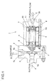
- FIG. 1 is a cross-sectional view showing the construction of a CO 2 pump in accordance with an embodiment of the prevent invention.
- FIG. 1 is a cross-sectional view showing the construction of a CO 2 pump in accordance with an embodiment of the present invention.
- a pump 1 comprises a discharge/suction-side casing 2, a purging-side casing 3 and an outer cylinder 4 being held therebetween. Outside the suction/discharge-side casing 2 is installed a manifold 5 which sucks and discharges the liquid being pumped.
- a canned motor 6 which drives the pump 1, comprising a stator 6a outside thereof and a rotor 6b being housed inside the stator 6a.
- the rotor 6b is installed to a main shaft 7; and the main shaft 7 is supported on both ends thereof by an angular ball bearing 8 being installed to the discharge/suction-side casing 2 and an angular ball bearing 9 being installed to the purging-side casing 3 so as to rotate, specifically, being axially supported.
- an impeller 10 which is mounted to one end of the main shaft 7 and can rotate, working simultaneously with the main shaft 7.
- the manifold 5 has a suction port 5a for the liquid being pumped opened on the extension shaft line from one end of the main shaft 7; and has a spiral casing 5b mounted around the impeller 10. Additionally, a discharge port 5c is opened from one point of the periphery part of a pathway 5b toward the outer peripheral surface of the manifold 5 in a radial direction.
- the purging-side casing 3 has a purging port 3a opened on the extension shaft line form the other end of the main shaft 7, which discharges a part of sucked liquid being pumped.
- a preload spring 11 is held between the purging-side casing 3 and the angular ball bearing 9.
- the preload spring 11 is a corrugated plate spring in the shape of a ring being located in the vicinity of the other end of the main shaft 7 and provides an axial preload to the angular ball bearing 9, serving as a constant-pressure spring method.
- the angular ball bearing 8 is referred as an impeller-side bearing
- the angular ball bearing 9 is referred as a shaft-end-side bearing.
- ceramic materials for example, silicon nitride Si 3 N 4 , alumina Al 2 O 3 , silicon carbide SiO 2 and the like
- the bearing members totally formed of a ceramic, wear resistance against particles being brought from the outside is enhanced, and further, in application in which metal particles (particles of wear) are not permitted, favorable effects can be achieved on prevention against metal pollution.
- the cage is designed in a manner that the drag loss (rotational resistance) becomes smaller. By this, it is possible to prevent the revolution skidding and reduce the preload (the thrust bearing load), so that the service life of the bearings can be extended.
- a PEEK material polyether ether ketone
- the strength is increased further.
- the ratio of the ball diameter versus the radii of the orbit slots of the inner and outer rings is optimized in order to enhance wear resistance and detachment resistance in high-speed and high-load conditions.
- solid lubricants such as PTFE, carbon and the like, wear resistance of the ball bearings in supercritical CO 2 fluid or liquid CO 2 which has inferior lubricating property is enhanced,.
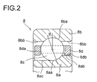
- FIG. 2 is a schematic cross-sectional view showing the bearing in accordance with the embodiment of the present invention.
- FIG. 2 shows a case of the angular ball bearing 8, but the angular ball bearing 9 is formed only in a manner that FIG. 2 is flipped horizontal, and basically, has the same construction.
- the angular ball bearing 8 in accordance with the embodiment comprises an inner ring 8a, an outer ring 8b, balls 8c being held therebetween and a cage 8d holding the balls 8c.
- the inner periphery of the outer ring 8b consists of an orbit slot 8ba where the ball 8c rolls and inner peripheral surfaces 8bb on both sides in the axial direction thereof.
- the outer periphery of the inner ring 8a consists of an orbit slot 8aa where the ball 8c rolls, the outermost peripheral surface 8ab on one side in the axial direction and the outer peripheral surface 8ac on the other side which continues form the orbit slot 8aa.
- the cage 8d is a ring-shaped member being installed between the inner ring 8a and the outer ring 8b, and at the predetermined locations over the whole periphery thereof are provided pockets 8da having the ball 8c caught therein, being equiangularly spaced.
- " ⁇ " in the figure is a contact angle.
- the ball bearing of a conventional CO 2 pump is totally formed of stainless steal, or has only the balls formed of a ceramic but has the inner and outer rings formed of stainless steel.
- the bearing in accordance with the embodiment is a totally ceramic bearing, wherein the balls and the inner and outer rings are formed of a ceramic.
- the cage of the conventional bearing is guided by both sides of the outer ring, being guided by the inner peripheral surfaces on both sides in the axial direction of the outer ring.
- the cage of the bearing in accordance with the embodiment is guided by the inner ring, and more precisely, is guided by one side of the inner ring, being guided by the outer peripheral surface on one side in the axial direction of the inner ring.
- the inner peripheral surface 8db of the cage 8d facing opposed to the outermost peripheral surface 8ab of the inner ring 8a is guided by the outermost peripheral surface 8ab of the inner ring 8a.
- This will enable the cage 8d to rotate easily in accordance with rotation of the inner ring 8a, thereby decreasing the rotational resistance (the drag loss) of the cage 8d, which can achieve prevention of the revolution skidding of the bearing.
- such means is possible to reduce the drag loss as employing a totally ceramic bearing having no cage.
- the ball bearing in accordance with the embodiment is designed in order to achieve both seize resistance and extension of operating life by adjusting the ratio of the ball diameter versus the radii of the orbit slots of the inner and outer rings (the ratio of the slot radius).
- it is desirable that the range of the ratio of the slot radius is within the range from 52 to 56 % or is larger than 54%, especially.
- the bearing in accordance with the embodiment of the present invention will be descried in details.
- the bearing in the accordance with the embodiment is an angular ball bearing as shown in FIG. 3, comprising an outer ring 112, an inner ring 113, balls 114 installed therebetween, serving as a plurality of rolling elements, and a cage 115 holding the balls 114.
- the outer ring 112, the inner ring 113 and the balls 114 are all formed of silicone nitride and the cage 115 is formed of PEEK, a super engineering plastic.
- the cage 115 is formed in a manner that the outside diameter thereof is slightly smaller than the inside diameter of the outer ring 112 (for approximately 0.15 mm) in order to rotate smoothly, being guided by the outer ring 112 serving as a fixed ring.
- the outer ring 112 comprises a small diameter part 112a which is the left half thereof, having the slightly larger inside diameter than the outside diameter of the cage 115 (for approximately 0.15 mm); and a large diameter part 112b which is the right half thereof, having the sufficiently larger inside diameter than the outside diameter of the cage 115; wherein the orbit slot of the outer ring 112 is formed so as to cover both the small diameter part 112a and the large diameter part 112b.
- the guide surface guiding the cage 115 is formed only on one side of the outer ring 112 in the axial direction (on the left side to the center of the balls).
- the "sufficiently large inside diameter" mentioned above means that when the outside ring 112 and the cage 115 rotate relatively, the distance between the facing surfaces of the outside ring 112 and the cage 115 in the left half is large enough to have almost no traction act between the facing surfaces.
- the antifriction bearing 111 shown in FIG. 4 is different from the antifriction shown in FIG. 3 only in the cage.
- the cage 116 has the inside diameter thereof increased to be slightly larger than the outside diameter of the inner ring 113 in order to rotate smoothly, being guided by the inner ring 113 serving as a rotating ring.
- FIG. 5 shows an evaluation equipment of the above-mentioned antifriction bearing 111.
- the evaluation equipment 121 evaluates the revolution skidding of the antifriction bearing 111, comprising a cylindrical housing 122 and a rotating shaft 123 being housed so as to rotate relatively thereto, wherein the antifriction bearings 111 and 111 on both right and left sides which support the rotating shaft 123, rotating, are installed at two locations being axially separated between the housing 122 and the rotating shaft 123.
- the rotating shaft 123 has the left end part thereof connected to the driving part (not illustrated) of an air turbine.
- a cylindrical coil spring 124 which loads the axial load thereto, while a cylindrical spacer 125 exists on the inner ring side.
- a non-contact displacement gauge 126 is installed so as to face the right end surface of the antifriction bearing 111 on the right side.
- the predetermined parts in the circumferential direction of the right-side surface of the cage 115 of the antifriction bearing 111 on the right side is coated with aluminum, thereby enabling the displacement gauge 115 to detect the frequencies of the aluminum coating part of the cage 115, so that the rotation speed of the cage 115, namely, the revolution speed of the balls 114, can be obtained from the frequencies.
- the ratios of the revolution skidding obtained in the above-mentioned manner are shown in FIG. 6 and FIG. 7.
- the white triangles (and the broken line “a") show the ratios of the revolution skidding of the antifriction bearing 111 being guided by one side of the outer ring (FIG. 3) when the axial load is 6.5 kgf;
- the white squares (and the broken line “b") show the ratios of the revolution skidding of the same bearing 111 when the axial load is 23 kgf;
- the black triangles (and the broken line “c") show the ratios of the revolution skidding of the antifriction bearing being guided by both sides of the outer ring when the axial load is 6.5 kgf (a comparative example);
- the black squares (and the broken line “d") show the ratios of the revolution skidding of the same bearing when the axial load is 23 kgf.
- the ratios of the revolution skidding becomes small, compared with the antifriction bearing having the guide surface formed on both sides in the axial direction, and the revolution skidding that deteriorates the wear performance of the antifriction bearing 111 is improved.
- the white triangles (and the broken line “a") show the ratios of the revolution skidding of the antifriction bearing 111 being guided by one side of the inner ring (FIG. 4) when the axial load is 6.5 kgf
- the white squares (and the broken line “b") show the ratios of the revolution skidding of the same bearing 111 when the axial load is 23 kgf
- the black triangles (and the broken line “c") show the ratios of the revolution skidding of the antifriction bearing being guided by both sides of the outer ring when the axial load is 6.5 kgf (a comparative example);
- the black squares (and the broken line “d") show the ratios of the revolution skidding of the same bearing when the axial load is 23 kgf.
- the ratios of the revolution skidding becomes significantly small, compared with the antifriction bearing being guided by the outer ring and having the guide surface formed on both sides in the axial direction, and the revolution skidding that deteriorates the wear performance of the antifriction bearing 111 is remarkably improved.
- FIG. 6 and FIG. 7 show the results of tests employing water.
- gravity and viscosity become small, compared with water, so that effects can surely be expected. Therefore, in accordance with the bearings 111 shown in FIG. 3 and FIG. 4, endurance thereof is prevented from deteriorating, thereby making it possible to operate the supercritical CO 2 pump employing the antifriction bearings as described continuously for a long time although the bearings are subject to be a severe condition of being in the supercritical CO 2 atmosphere.
- the PV value will decrease from 747 (MPa • m/s) to 553 (MPa • m/s) where the axial load is 50N, and the PV value will decrease from 935 (MPa - m/s) to 708 (MPa • m/s) where the axial load is 100N and will decrease to be approximately 3/4 on an average.
- the PV value can be lowered in this way, thereby reducing the wear.
- the above-mentioned effect can be achieved by making the area of contact on the side of the inner ring 113 small so as to lower the PV value in a case where the skidding occurs on the side of the inner ring 113 .
- the upper limit of the curvature radius of the orbit slot of the inner ring is determined to be approximately as much as 60% of the ball diameter, considering the relation with the other performances.
- the curvature radius of the orbit slot of the outer ring is not limited specifically, but may be more than 50.5% and no greater than 60%.
- the supercritical CO 2 is generally used in the range from 35°C to 100°C.
- the linear expansion coefficient between the main shaft member of the motor and the inner ring of the bearing supporting the shaft member there is a difference in the linear expansion coefficient between the main shaft member of the motor and the inner ring of the bearing supporting the shaft member.
- austenite stainless steel is generally applied to the main shaft member, considering corrosion resistance, the linear expansion coefficient of the main shaft member is large, while the linear expansion coefficient of the inner ring of the bearing is small because the inner ring of the bearing is formed of a ceramic as described hereinabove.
- FIG. 8 shows the construction of the impeller side, and the construction of the shaft end side is the same although there are no bolts.
- the bearing in accordance with the present invention employs balls for rolling elements thereof, so as to be a ball bearing, but not limited to.
- the bearing may be a roller bearing that employs a cylindrical roller or a roller in the form of a circular truncated cone.
Landscapes
- Engineering & Computer Science (AREA)
- General Engineering & Computer Science (AREA)
- Mechanical Engineering (AREA)
- Structures Of Non-Positive Displacement Pumps (AREA)
- Rolling Contact Bearings (AREA)
- Compressor (AREA)
- Details Of Reciprocating Pumps (AREA)
Abstract
Description
- The present invention relates to a pump which carries supercritical CO2 fluid or liquid CO2
- Because supercritical fluid can continuously change the volume (density) thereof by regulating the temperature and pressure, values of various properties such as dissolution characteristic and the like can be easily controlled, which makes it possible to utilize supercritical fluid as a refrigerant. Additionally, because the viscosity thereof is low but the diffusivity thereof is high, supercritical fluid is expected to be used for washing; or is expected to be used as a refrigerant because the thermal conductivity thereof is high.
- Being easy to get and good in handling and the like because of not having explosive nature, inflammability and the like, water, CO2 and the like are generally used as supercritical fluid. Especially, CO2 has characteristics that the critical temperature is 31°C and the critical pressure is 7.38 Mpa; that the temperature and the pressure are low but manageability is superior, being compared with other materials; that CO2 is a gaseous body at the atmospheric pressure and the ambient temperature; and the like. Therefore, CO2 is made wide use of as an extracting solvent for materials which are easily affected by heat (such as foods, flavoring ingredients and the like) and as a cleaning agent and the like which utilize the drying characteristics and permeability thereof. Additionally, CO2 is generally used by being pressurized up to no less than 7 to 20 MPa in an extracting equipment or a cleaning equipment that employs the supercritical CO2.
- Because a pump for carrying CO2 in such an equipment as mentioned hereinabove is used at high pressure, so-called sealless canned motor type of pump is adopted. In some cases, ball bearings are employed as the bearings and used in solution (supercritical CO2) However, when the pump is used for the food sector or semi-conductor sector, wear of the bearings cannot be permitted in order to prevent foreign objects (particles) from occurring inside the pump.
- As an example of the pump, a turbo-molecular pump is disclosed in
Patent Literature 1. In addition, a canned motor type of pump is disclosed in Patent Literature 2. As for the rest, a semi-conductor manufacturing method and a semi-conductor manufacturing equipment are disclosed inPatent Literature 3, which prevent heavy-metal contamination of extra-pure water being manufactured by an extra-pure water manufacturing system for manufacturing of semi-conductors. - Patent Literature 1: Patent Application Laid Open as H10-274188
- Patent Literature 2: Patent Application Laid Open as 2000-9077
- Patent Literature 3: Patent Application Laid Open as 2003-124177
- Because ball bearings are used in supercritical CO2 (or liquid CO2) of low viscosity, lubrication by liquid being pumped cannot be expected and the environmental condition is severe for the wear of the bearings. Additionally, in a cleaning equipment and the like, in order to enhance the cleaning capability thereof further, there is a case where cleaning chemical is mixed into CO2. Therefore, there is a concern of corrosion and the like of the ball bearings being caused by chemicals.
- The above-mentioned ball bearings receive the radial load and thrust load which act on a rotor. Additionally, a pump is constructed in a manner that the preload is supplied by a bearing preload spring which is installed to the bearing on the shaft-end side, being opposite to the bearing on the impeller side which will be described later, so as to prevent so-called revolution skidding (side skidding) of the bearings. However, because the pump being so constructed as described above is used in the liquid being pumped (what is called "in a condition of being thoroughly immersed"), rotational resistance (a loss due to agitation) of balls and a cage is large so that the revolution skidding of bearings is easy to occur. Therefore, there arises a case where it is necessary to apply a large preload in order to prevent the revolution skidding.
- On the other hand, in order to secure the life of the bearings, it is desirable to make the bearing load including the preload as small as possible. However, because the bearings are used in the liquid being pumped, the pump must be designed, taking prevention of the revolution skidding into consideration.
- It is an object of the prevent invention to provide a pump for carrying supercritical CO2 fluid or liquid CO2 capable of securing reliability by optimizing a bearing part.
- In order to achieve the above-mentioned object, a pump for carrying supercritical CO2 fluid or CO2 liquid in accordance with the present invention has bearings which axially support the main shaft of a motor driving the pump, wherein inner rings, outer rings and balls (rolling elements) thereof are formed of a ceramic material, respectively.
- Additionally, a cage holding the balls is guided by the outer ring, being guided by the inner peripheral surface of the outer ring, or guided by the inner ring, being guided by the outer peripheral surface of the inner ring; wherein the surface being guided by the outer ring or the inner ring is both of the side surfaces or one side surface in the axial direction.
- Moreover, the ratio of the slot radius of the inner ring of the bearing is more than 52%, and the main shaft is hollow.
- The curvature radius of the orbit slot of the inner ring heretofore known is no less than 52% as specified, for example, by the JIS standards. Especially, in a high-speed rotating range, antifriction bearings that are used in the atmosphere of supercritical CO2 fluid are easy to wear, wherein the wear is presumed to be significantly attributed to skidding caused by spinning. Balls of an angular ball bearing generally roll on the plane of the orbit of either the inner ring or the outer ring almost without skidding, while spinning occurs on the other plane of the orbit.
- In addition, in the angular ball bearing, the curvature radius of the orbit slot of the inner ring is smaller than that of the outer ring, and the major axis of the osculating ellipse is long when a load is applied. As a result, in the inner ring, spinning motion of the balls is disturbed (being guided by the inner ring), which causes complete spinning motion to occur on the orbit of the outer ring. However, when the rotation speed becomes high (and the load becomes small), effects of a centrifugal force become large, easily causing the cage to be guided by the outer ring.
- In the present invention, attention is focused on the skidding due to spinning which significantly contributes to the wear and on the curvature radius of the orbit slot of the inner ring, and by lowering the PV value that is obtained by the skidding due to spinning (product of the bearing surface pressure "P" multiplied by the skidding speed "V"), the wear can be reduced. More specifically, by making the curvature radius of the orbit slot of the inner ring larger than the standard value so as to make the area of contact of the balls with the orbit slot small, the PV value is decreased.
- Because the balls, the inner ring and the outer ring of the antifriction bearing for the supercritical CO2 pump in accordance with the present invention are formed of a ceramic, wear resistance is enhanced; wherein, additionally, the curvature radius of the orbit slot of the inner ring is larger than 52% of the ball diameter, and especially, larger than 54%, the area of contact on the inner ring side becomes small. In the result, the PV value becomes small, which makes it possible to reduce the wear further. Consequently, reduction in endurance of the antifriction bearing is prevented, so that a supercritical CO2 pump employing the antifriction bearings will not cause a problem that it cannot be used continuously because the vibration becomes high.
- In addition, the upper limit of the curvature radius of the orbit slot of the inner ring is not specifically limited, but is no more than 60% of the ball diameter, considering the other performances. Also, the curvature radius of the orbit slot of the outer ring is not specifically limited, but is generally more than 50.5% and not greater than 60%.
- Moreover, the cage holding the balls is guided by a rotating ring. Or, the cage holding the balls is guided by a fixed ring, wherein the guide surface is formed only on one side to the center of the balls in the axial direction.
- In order to have the guide surface of a fixed ring formed only on one side in the axial direction, in case of being guided by the fixed ring, the inside diameter of the outer ring on one side in the axial direction may be made large so as not to have the inner peripheral surface of the large diameter part of the outer ring contact the outer peripheral surface of the cage; or the outside diameter of the cage on one side in the axial direction may be made small so as not to have the outer peripheral surface of the small diameter part of the cage contact the inner peripheral surface of the outer ring. In addition, in case of being guided by a rotating ring, the outside diameter of the inner ring on one side in the axial direction may be made small so as not to have the outer peripheral surface of the small diameter part of the inner ring contact the inner peripheral surface of the cage; or the inside diameter of the cage on one side in the axial direction may be made large so as not to have the inner peripheral surface of the large diameter part of the cage contact the outer peripheral surface of the inner ring.
- In the antifriction bearing which is used in a fluid atmosphere, revolution of rolling elements (balls) [rotation of the cage] is delayed mainly by resistance of the fluid, especially in a high-speed rotation range, causing skidding (revolution skidding) to occur between the orbit ring and the rolling elements which must be in contact while rolling. When the revolution skidding occurs, the orbit ring and the rolling elements cannot sometimes be used continuously because they get damaged in a short time. In the present invention, an attention is focused on this revolution skidding, and by restraining the revolution skidding, antifriction bearings can be used continuously.
- Specifically, by having the cage guided by a rotating ring, delay in revolution of the cage is decreased by a traction force due to contact with the rotating ring and a traction force of the fluid in the guide part (by driving the cage in the direction of revolution), thereby restraining the revolution skidding. And also, by having the cage guided by a fixed ring so as to have the guide surface formed only on one side to the center of the rolling elements in the axial direction, the resistance which is applied to the rolling cage by the fixed ring (friction due to contact and viscosity resistance of the fluid) is decreased, thereby restraining the revolution skidding.
- In accordance with the present invention, a pump for carrying supercritical CO2 fluid or liquid CO2, capable of securing reliability by optimizing a bearing part can be supplied.
- Specifically, by employing a totally ceramic bearing, it is possible to enhance the corrosion resistance against a cleaning agent. Additionally, it is possible to reduce a centrifugal force due to high-speed rotation, enhance wear resistance and prevent damages caused by particles coming from the outside.
- Moreover, by reducing the drag loss of the cage, damages caused by the revolution skidding of a bearing can be prevented. Also, by enhancing the characteristic of the revolution skidding, the preload can be decreased, which reduces the thrust load, thereby achieving extension of operating life of the bearing. Additionally, by decreasing the drag loss, efficiency of the pump can be enhanced.
- For the rest, by optimizing the ratio of the ball diameter versus the radius of the orbit slot (ratio of the slot radius), seize resistance can be improved and at the same time, extension of operation life can be achieved, thereby achieving optimization. Also, by applying a PEEK member to the material of the cage, corrosion resistance and strength of the cage can be enhanced.
- Moreover, when a totally ceramic bearing is employed, there is a concern of a damage being caused by excessive stress of shrinkage of the inner ring of the bearing due to thermal expansion differential between the main shaft and the inner ring of the bearing that occurs when the temperature ascends. However, this can be avoided by having the main shaft formed to be a hollow shaft.
- Also, by having the cage of an antifriction bearing guided by a rotating ring, a force driving in the direction of revolution from the fluid in the rotating ring and the guide part acts on the rolling elements, thereby restraining the revolution skidding. In consequence, endurance of the antifriction bearing can be prevented from deteriorating, so that such a problem will not occur as a pump for supercritical CO2 employing this antifriction bearing cannot be used continuously because the vibration becomes higher.
- Or, by having the cage guided by a fixed ring and having the guide surface formed only on one side to the center of the rolling elements in the axial direction, it is possible to reduce a force which disturbs movement of the rolling elements to the direction of revolution, thereby restraining the revolution skidding. In consequence, endurance of the antifriction bearing can be prevented from deteriorating, so that such a problem will not occur as a pump for supercritical CO2 employing this antifriction bearing cannot be used continuously because the vibration becomes higher.
- FIG. 1 is a cross-sectional view showing the construction of a CO2 pump in accordance with an embodiment of the prevent invention.
- FIG. 2 is a schematic cross-sectional view showing a bearing in accordance with the embodiment.
- FIG. 3 is a longitudinal cross-sectional view showing an antifriction bearing in accordance with the embodiment.
- FIG. 4 is a longitudinal cross-sectional view showing an antifriction bearing in accordance with the embodiment.
- FIG. 5 is a longitudinal cross-sectional view showing an evaluation equipment of the antifriction bearing in accordance with the embodiment.
- FIG. 6 is a graph showing the results of evaluation of the antifriction bearing.
- FIG. 7 is a graph showing the results of evaluation of the antifriction bearing.
- FIG. 8 is a schematic cross-sectional view showing the condition of the main shaft which is hollow.
-
- 1:
- Circulation Pump
- 2:
- Discharge-Side/Suction-Side Casing
- 3:
- Purging-Side Casing
- 4:
- External Cylinder
- 5:
- Manifold
- 6:
- Canned Motor
- 7:
- Main Shaft
- 8 and 9:
- Angular Ball Bearing
- 10:
- Impeller
- 11:
- Preload Spring
- Referring now to the drawings, an embodiment of the present invention will be described hereinafter. FIG. 1 is a cross-sectional view showing the construction of a CO2 pump in accordance with an embodiment of the present invention. A
pump 1 comprises a discharge/suction-side casing 2, a purging-side casing 3 and anouter cylinder 4 being held therebetween. Outside the suction/discharge-side casing 2 is installed amanifold 5 which sucks and discharges the liquid being pumped. - Inside the
outer cylinder 4 is installed a canned motor 6 which drives thepump 1, comprising a stator 6a outside thereof and arotor 6b being housed inside the stator 6a. Therotor 6b is installed to amain shaft 7; and themain shaft 7 is supported on both ends thereof by anangular ball bearing 8 being installed to the discharge/suction-side casing 2 and anangular ball bearing 9 being installed to the purging-side casing 3 so as to rotate, specifically, being axially supported. - Between the discharge/suction-side casing 2 and the
manifold 5 is installed animpeller 10, which is mounted to one end of themain shaft 7 and can rotate, working simultaneously with themain shaft 7. Themanifold 5 has asuction port 5a for the liquid being pumped opened on the extension shaft line from one end of themain shaft 7; and has a spiral casing 5b mounted around theimpeller 10. Additionally, adischarge port 5c is opened from one point of the periphery part of a pathway 5b toward the outer peripheral surface of themanifold 5 in a radial direction. - On the other hand, the purging-
side casing 3 has a purging port 3a opened on the extension shaft line form the other end of themain shaft 7, which discharges a part of sucked liquid being pumped. As for the rest, apreload spring 11 is held between the purging-side casing 3 and theangular ball bearing 9. Thepreload spring 11 is a corrugated plate spring in the shape of a ring being located in the vicinity of the other end of themain shaft 7 and provides an axial preload to theangular ball bearing 9, serving as a constant-pressure spring method. In addition, theangular ball bearing 8 is referred as an impeller-side bearing, while theangular ball bearing 9 is referred as a shaft-end-side bearing. - In the
pump 1 as described hereinabove, when therotor 6b of the canned motor 6 and themain shaft 7 rotate, causing theimpeller 10 to rotate simultaneously, the liquid being pumped is sucked through thesuction port 5a as shown with an arrow "A," introduced into the pathway 5b by the centrifugal force of theimpeller 10 and is discharged through thedischarge port 5c in the end as shown with an arrow "B." Additionally, a part of the liquid being pumped and sucked through thesuction port 5a passes through the inside of theangular ball bearings - Now, in the present invention, in order to enhance wear resistance and corrosion resistance and reduce the centrifugal load during high-speed rotation, ceramic materials (for example, silicon nitride Si3N4, alumina Al2 O3, silicon carbide SiO2 and the like) are employed for the inner and outer rings and the balls of the angular ball bearing. By having the bearing members totally formed of a ceramic, wear resistance against particles being brought from the outside is enhanced, and further, in application in which metal particles (particles of wear) are not permitted, favorable effects can be achieved on prevention against metal pollution.
- Additionally, the cage is designed in a manner that the drag loss (rotational resistance) becomes smaller. By this, it is possible to prevent the revolution skidding and reduce the preload (the thrust bearing load), so that the service life of the bearings can be extended. In order to secure corrosion resistance and wear resistance against the cleaning agent and maintain the strength for high-speed rotation, a PEEK material (polyether ether ketone) is used for the material of the cage. As for this, by using the PEEK material containing 30% glass fiber, for example, the strength is increased further. In addition, the ratio of the ball diameter versus the radii of the orbit slots of the inner and outer rings is optimized in order to enhance wear resistance and detachment resistance in high-speed and high-load conditions. Moreover, by containing solid lubricants such as PTFE, carbon and the like, wear resistance of the ball bearings in supercritical CO2 fluid or liquid CO2 which has inferior lubricating property is enhanced,.
- FIG. 2 is a schematic cross-sectional view showing the bearing in accordance with the embodiment of the present invention. FIG. 2 shows a case of the
angular ball bearing 8, but theangular ball bearing 9 is formed only in a manner that FIG. 2 is flipped horizontal, and basically, has the same construction. As shown in FIG. 2, theangular ball bearing 8 in accordance with the embodiment comprises aninner ring 8a, anouter ring 8b,balls 8c being held therebetween and acage 8d holding theballs 8c. - The inner periphery of the
outer ring 8b consists of an orbit slot 8ba where theball 8c rolls and inner peripheral surfaces 8bb on both sides in the axial direction thereof. Also, the outer periphery of theinner ring 8a consists of an orbit slot 8aa where theball 8c rolls, the outermost peripheral surface 8ab on one side in the axial direction and the outer peripheral surface 8ac on the other side which continues form the orbit slot 8aa. Additionally, thecage 8d is a ring-shaped member being installed between theinner ring 8a and theouter ring 8b, and at the predetermined locations over the whole periphery thereof are provided pockets 8da having theball 8c caught therein, being equiangularly spaced. In addition, "α" in the figure is a contact angle. - The ball bearing of a conventional CO2 pump is totally formed of stainless steal, or has only the balls formed of a ceramic but has the inner and outer rings formed of stainless steel. However, as described hereinabove, the bearing in accordance with the embodiment is a totally ceramic bearing, wherein the balls and the inner and outer rings are formed of a ceramic. In addition, the cage of the conventional bearing is guided by both sides of the outer ring, being guided by the inner peripheral surfaces on both sides in the axial direction of the outer ring. However, the cage of the bearing in accordance with the embodiment is guided by the inner ring, and more precisely, is guided by one side of the inner ring, being guided by the outer peripheral surface on one side in the axial direction of the inner ring.
- Specifically, in FIG. 2, the inner peripheral surface 8db of the
cage 8d facing opposed to the outermost peripheral surface 8ab of theinner ring 8a is guided by the outermost peripheral surface 8ab of theinner ring 8a. This will enable thecage 8d to rotate easily in accordance with rotation of theinner ring 8a, thereby decreasing the rotational resistance (the drag loss) of thecage 8d, which can achieve prevention of the revolution skidding of the bearing. Moreover, such means is possible to reduce the drag loss as employing a totally ceramic bearing having no cage. - Additionally, seize resistance and extension of operating life of a ball bearing are contradictory. Therefore, the ball bearing in accordance with the embodiment is designed in order to achieve both seize resistance and extension of operating life by adjusting the ratio of the ball diameter versus the radii of the orbit slots of the inner and outer rings (the ratio of the slot radius). The range of the ratio of the slot radius is more than "the slot radius/the ball diameter × 100 = 52%." Furthermore, it is desirable that the range of the ratio of the slot radius is within the range from 52 to 56 % or is larger than 54%, especially.
- The bearing in accordance with the embodiment of the present invention will be descried in details. The bearing in the accordance with the embodiment is an angular ball bearing as shown in FIG. 3, comprising an
outer ring 112, aninner ring 113,balls 114 installed therebetween, serving as a plurality of rolling elements, and acage 115 holding theballs 114. Theouter ring 112, theinner ring 113 and theballs 114 are all formed of silicone nitride and thecage 115 is formed of PEEK, a super engineering plastic. - The
cage 115 is formed in a manner that the outside diameter thereof is slightly smaller than the inside diameter of the outer ring 112 (for approximately 0.15 mm) in order to rotate smoothly, being guided by theouter ring 112 serving as a fixed ring. Then, theouter ring 112 comprises asmall diameter part 112a which is the left half thereof, having the slightly larger inside diameter than the outside diameter of the cage 115 (for approximately 0.15 mm); and alarge diameter part 112b which is the right half thereof, having the sufficiently larger inside diameter than the outside diameter of thecage 115; wherein the orbit slot of theouter ring 112 is formed so as to cover both thesmall diameter part 112a and thelarge diameter part 112b. - By this, the guide surface guiding the
cage 115 is formed only on one side of theouter ring 112 in the axial direction (on the left side to the center of the balls). In addition, the "sufficiently large inside diameter" mentioned above means that when theoutside ring 112 and thecage 115 rotate relatively, the distance between the facing surfaces of theoutside ring 112 and thecage 115 in the left half is large enough to have almost no traction act between the facing surfaces. - The
antifriction bearing 111 shown in FIG. 4 is different from the antifriction shown in FIG. 3 only in the cage. Thecage 116 has the inside diameter thereof increased to be slightly larger than the outside diameter of theinner ring 113 in order to rotate smoothly, being guided by theinner ring 113 serving as a rotating ring. - FIG. 5 shows an evaluation equipment of the above-mentioned
antifriction bearing 111. Theevaluation equipment 121 evaluates the revolution skidding of theantifriction bearing 111, comprising acylindrical housing 122 and arotating shaft 123 being housed so as to rotate relatively thereto, wherein theantifriction bearings rotating shaft 123, rotating, are installed at two locations being axially separated between thehousing 122 and therotating shaft 123. - The
rotating shaft 123 has the left end part thereof connected to the driving part (not illustrated) of an air turbine. On the outer ring side between the twoantifriction bearings 111 exists acylindrical coil spring 124 which loads the axial load thereto, while acylindrical spacer 125 exists on the inner ring side. Then, anon-contact displacement gauge 126 is installed so as to face the right end surface of the antifriction bearing 111 on the right side. - The predetermined parts in the circumferential direction of the right-side surface of the
cage 115 of the antifriction bearing 111 on the right side is coated with aluminum, thereby enabling thedisplacement gauge 115 to detect the frequencies of the aluminum coating part of thecage 115, so that the rotation speed of thecage 115, namely, the revolution speed of theballs 114, can be obtained from the frequencies. - By employing the above-mentioned
evaluation equipment 121, the revolution speed "nC" of theballs 114 of theantifriction bearing 111 is measured; and by obtaining the "ratio of the revolution skidding (%) = (nT - nC) / nT × 100" from the measured revolution speed "nC" and the revolution speed "nT" obtained theoretically, the revolution skidding of antifriction bearings of different specification can be evaluated; wherein, "nT" can be obtained by "nT=the rotation speed of the inner ring×(1- the ball diameter × cos α / the pitch diameter of the ball) / 2," where "α" is a contact angle. The ratios of the revolution skidding obtained in the above-mentioned manner are shown in FIG. 6 and FIG. 7. - In the graph in FIG. 6, the white triangles (and the broken line "a") show the ratios of the revolution skidding of the
antifriction bearing 111 being guided by one side of the outer ring (FIG. 3) when the axial load is 6.5 kgf; the white squares (and the broken line "b") show the ratios of the revolution skidding of thesame bearing 111 when the axial load is 23 kgf; the black triangles (and the broken line "c") show the ratios of the revolution skidding of the antifriction bearing being guided by both sides of the outer ring when the axial load is 6.5 kgf (a comparative example); and the black squares (and the broken line "d") show the ratios of the revolution skidding of the same bearing when the axial load is 23 kgf. As can be seen from the graph, in the antifriction bearing 111 shown in FIG. 3, the ratios of the revolution skidding becomes small, compared with the antifriction bearing having the guide surface formed on both sides in the axial direction, and the revolution skidding that deteriorates the wear performance of theantifriction bearing 111 is improved. - In the graph in FIG. 7, the white triangles (and the broken line "a") show the ratios of the revolution skidding of the
antifriction bearing 111 being guided by one side of the inner ring (FIG. 4) when the axial load is 6.5 kgf the white squares (and the broken line "b") show the ratios of the revolution skidding of thesame bearing 111 when the axial load is 23 kgf the black triangles (and the broken line "c") show the ratios of the revolution skidding of the antifriction bearing being guided by both sides of the outer ring when the axial load is 6.5 kgf (a comparative example); and the black squares (and the broken line "d") show the ratios of the revolution skidding of the same bearing when the axial load is 23 kgf. As can be seen from the graph, in the antifriction bearing 111 shown in FIG. 4, the ratios of the revolution skidding becomes significantly small, compared with the antifriction bearing being guided by the outer ring and having the guide surface formed on both sides in the axial direction, and the revolution skidding that deteriorates the wear performance of theantifriction bearing 111 is remarkably improved. - FIG. 6 and FIG. 7 show the results of tests employing water. In the atmosphere of supercritical CO2, gravity and viscosity become small, compared with water, so that effects can surely be expected. Therefore, in accordance with the
bearings 111 shown in FIG. 3 and FIG. 4, endurance thereof is prevented from deteriorating, thereby making it possible to operate the supercritical CO2 pump employing the antifriction bearings as described continuously for a long time although the bearings are subject to be a severe condition of being in the supercritical CO2 atmosphere. - The results of analysis of the properties of the ball bearing in accordance with the embodiment will be descried hereinafter. Herein, effects of making the curvature radius of the orbit slot of the
inner ring 113 larger than 54% of the ball diameter will be described by giving the results of calculation with an angular bearing having the inside diameter of Φ 10 as a concrete example. - To put it simply, when the curvature radius of the orbit slot of the inner ring is changed from 52% to 56% of the ball diameter, the PV value will decrease from 747 (MPa • m/s) to 553 (MPa • m/s) where the axial load is 50N, and the PV value will decrease from 935 (MPa - m/s) to 708 (MPa • m/s) where the axial load is 100N and will decrease to be approximately 3/4 on an average. The PV value can be lowered in this way, thereby reducing the wear.
- The above-mentioned effect can be achieved by making the area of contact on the side of the
inner ring 113 small so as to lower the PV value in a case where the skidding occurs on the side of theinner ring 113 . By analyzing in more details from this point of view, in order to lower the PV value effectively, it is desirable to make the curvature radius of the orbit slot of the inner ring larger than 54% of the ball diameter. The upper limit of the curvature radius of the orbit slot of the inner ring is determined to be approximately as much as 60% of the ball diameter, considering the relation with the other performances. The curvature radius of the orbit slot of the outer ring is not limited specifically, but may be more than 50.5% and no greater than 60%. - In now, the supercritical CO2 is generally used in the range from 35°C to 100°C. On the other hand, there is a difference in the linear expansion coefficient between the main shaft member of the motor and the inner ring of the bearing supporting the shaft member. To put it simply, because austenite stainless steel is generally applied to the main shaft member, considering corrosion resistance, the linear expansion coefficient of the main shaft member is large, while the linear expansion coefficient of the inner ring of the bearing is small because the inner ring of the bearing is formed of a ceramic as described hereinabove.
- Therefore, there is a concern that the inner ring of the bearing may be damaged due to expansion of the main shaft when the temperature ascends. Consequently, as shown in FIG. 8, by providing a
bored hole 7a to the center of the axis of themain shaft 7 serving as a hole for a mounting bolt of the impeller and making themain shaft 7 hollow, expansion of themain shaft 7 is let to go inward, thereby mitigating the stress which is generated in theinner ring 8a of theangular ball bearing 8. Here, FIG. 8 shows the construction of the impeller side, and the construction of the shaft end side is the same although there are no bolts. - The bearing in accordance with the present invention employs balls for rolling elements thereof, so as to be a ball bearing, but not limited to. The bearing may be a roller bearing that employs a cylindrical roller or a roller in the form of a circular truncated cone.
- It is to be understood that the present invention may be carried out in any other manner than specifically described above as an embodiment, and many modifications and variations are possible within the scope of the invention.
Claims (16)
- A pump carrying supercritical CO2 fluid or liquid CO2,
wherein, a bearing supporting a main shaft has an inner ring, an outer ring and balls thereof formed of a ceramic member, respectively. - A pump as described in Claim 1,
wherein, a cage holding the balls is guided by an outer ring, being guided by an inner peripheral surface of the outer ring; or is guided by an inner ring, being guided by an outer peripheral surface of an inner ring; and
wherein, a guide surface of an outer ring or an inner ring is a surface on one side in axial direction. - A pump as described in Claim 2,
wherein, the cage is formed of PEEK member. - A pump as described in Claim 1,
wherein, ratio of slot radius of inner ring of the bearing is more than 52%. - A pump as described in Claim 2,
wherein, ratio of slot radius of inner ring of the bearing is more than 52%. - A pump as described in Claim 3,
wherein, ratio of slot radius of inner ring of the bearing is more than 52%. - A pump as described in Claim 1,
wherein, the main shaft is hollow. - A pump as described in Claim 2,
wherein, the main shaft is hollow. - A pump as described in Claim 3,
wherein, the said main shaft is hollow. - A pump as described in Claim 4,
wherein, the main shaft is hollow. - A pump as described in Claim 5,
wherein, the main shaft is hollow. - A pump as described in Claim 6,
wherein, the main shaft is hollow. - A pump as described in Claim 1,
wherein, a cage holding the balls is guided by a rotating ring. - A pump as described in Claim 1,
wherein, a cage holding the balls is guided by a fixed ring; and
wherein, a guide surface is formed only on one side to center of the balls in axial direction. - A pump as described in Claim 2,
wherein, the cage contains solid lubricant. - A pump as described in Claim 3,
wherein the cage contains solid lubricant.
Applications Claiming Priority (2)
| Application Number | Priority Date | Filing Date | Title |
|---|---|---|---|
| JP2003203539A JP4008390B2 (en) | 2003-07-30 | 2003-07-30 | pump |
| PCT/JP2004/010337 WO2005012731A1 (en) | 2003-07-30 | 2004-07-21 | Pump |
Publications (3)
| Publication Number | Publication Date |
|---|---|
| EP1650438A1 true EP1650438A1 (en) | 2006-04-26 |
| EP1650438A4 EP1650438A4 (en) | 2007-01-24 |
| EP1650438B1 EP1650438B1 (en) | 2010-09-08 |
Family
ID=34113617
Family Applications (1)
| Application Number | Title | Priority Date | Filing Date |
|---|---|---|---|
| EP04770847A Expired - Lifetime EP1650438B1 (en) | 2003-07-30 | 2004-07-21 | Pump |
Country Status (6)
| Country | Link |
|---|---|
| US (1) | US7416344B2 (en) |
| EP (1) | EP1650438B1 (en) |
| JP (1) | JP4008390B2 (en) |
| DE (1) | DE602004029052D1 (en) |
| TW (1) | TWI281003B (en) |
| WO (1) | WO2005012731A1 (en) |
Families Citing this family (18)
| Publication number | Priority date | Publication date | Assignee | Title |
|---|---|---|---|---|
| JP5130841B2 (en) * | 2007-09-14 | 2013-01-30 | 日本精工株式会社 | Linear motion device |
| JP5291363B2 (en) * | 2008-03-14 | 2013-09-18 | 三菱重工業株式会社 | pump |
| GB2467965B (en) * | 2009-02-24 | 2015-04-22 | Dyson Technology Ltd | Rotor assembly |
| GB2467966B (en) * | 2009-02-24 | 2013-04-03 | Dyson Technology Ltd | Rotor assembly |
| US8439637B2 (en) * | 2009-11-20 | 2013-05-14 | United Technologies Corporation | Bellows preload and centering spring for a fan drive gear system |
| EP2505778B1 (en) * | 2010-11-29 | 2019-05-01 | NSK Ltd. | Air motor and electrostatic coating device |
| JP5874171B2 (en) * | 2011-02-23 | 2016-03-02 | 日本精工株式会社 | Combined angular contact ball bearing |
| US8777793B2 (en) | 2011-04-27 | 2014-07-15 | United Technologies Corporation | Fan drive planetary gear system integrated carrier and torque frame |
| DK2518867T3 (en) * | 2011-04-29 | 2017-07-17 | Welltec As | ELECTRICAL ENGINE |
| GB2493974B (en) | 2011-08-26 | 2014-01-15 | Dyson Technology Ltd | Bearing assembly |
| US10400629B2 (en) | 2012-01-31 | 2019-09-03 | United Technologies Corporation | Gas turbine engine shaft bearing configuration |
| US8863491B2 (en) | 2012-01-31 | 2014-10-21 | United Technologies Corporation | Gas turbine engine shaft bearing configuration |
| US9038366B2 (en) | 2012-01-31 | 2015-05-26 | United Technologies Corporation | LPC flowpath shape with gas turbine engine shaft bearing configuration |
| CN106337819A (en) * | 2015-07-13 | 2017-01-18 | 昆山江津长抗干磨磁力泵有限公司 | Structure-improved magnetic pump |
| CN204805110U (en) * | 2015-07-13 | 2015-11-25 | 昆山江津长抗干磨磁力泵有限公司 | Magnetic drive pump of institutional advancement |
| KR102289575B1 (en) * | 2017-08-10 | 2021-08-13 | 가부시키가이샤 후지킨 | Fluid supply device and fluid supply method |
| CN111809181B (en) * | 2020-07-10 | 2022-07-12 | 杭州领扬科技有限公司 | Method for improving carbon dioxide corrosion resistance of martensite heat-resistant steel |
| US12392286B2 (en) | 2022-10-17 | 2025-08-19 | General Electric Company | Pump systems having dual-function heat exchangers and related methods |
Family Cites Families (23)
| Publication number | Priority date | Publication date | Assignee | Title |
|---|---|---|---|---|
| JPH01315692A (en) | 1988-03-22 | 1989-12-20 | Teikoku Denki Seisakusho:Kk | Method of operating rotary pump for high purity liquid |
| JPH0814284B2 (en) | 1989-02-02 | 1996-02-14 | 株式会社ウイング・ハイセラ | Ceramic bearing |
| JPH068777U (en) * | 1992-07-07 | 1994-02-04 | 株式会社東芝 | Oil pump |
| JPH06193598A (en) * | 1992-08-19 | 1994-07-12 | Japan Atom Energy Res Inst | Very low temperature rotary equipment |
| US6558139B2 (en) | 1995-12-04 | 2003-05-06 | Chemical Seal & Packing, Inc. | Bearings with hardened rolling elements and polymeric cages for use submerged in very low temperature fluids |
| JPH09177792A (en) * | 1995-12-21 | 1997-07-11 | Ntn Corp | Cage for ball bearing and ball bearing |
| JPH10274188A (en) | 1997-03-31 | 1998-10-13 | Shimadzu Corp | Turbo molecular pump |
| JP3808994B2 (en) | 1997-11-26 | 2006-08-16 | シャープ株式会社 | Supercritical fluid cleaning equipment |
| JP2000009077A (en) | 1998-06-26 | 2000-01-11 | Hitachi Ltd | pump |
| JP4207271B2 (en) | 1998-10-26 | 2009-01-14 | 日本精工株式会社 | Seals, cages, rolling bearings |
| JP2000352377A (en) | 1999-06-08 | 2000-12-19 | Mitsubishi Heavy Ind Ltd | Open type compressor |
| FR2798433B1 (en) | 1999-09-14 | 2001-11-09 | Snfa | HYBRID BALL BEARING WITH ANGULAR CONTACT |
| EP1258015A4 (en) * | 2000-01-11 | 2003-04-23 | Gsi Lumonics Inc | TURNING DEVICE WITH CERAMIC BEARINGS WITH ADAPTED EXPANSION |
| JP2001336538A (en) * | 2000-05-26 | 2001-12-07 | Nsk Ltd | Rolling bearing and its manufacturing method |
| SE517535C2 (en) * | 2000-12-21 | 2002-06-18 | Skf Ab | Bearings |
| US6759774B1 (en) * | 2001-03-08 | 2004-07-06 | Lawrence Pumps, Inc | Low speed canned motor |
| JP2002357226A (en) | 2001-03-28 | 2002-12-13 | Nsk Ltd | Ball bearing |
| JP2002349582A (en) * | 2001-05-30 | 2002-12-04 | Koyo Seiko Co Ltd | Rolling bearing |
| JP3858972B2 (en) | 2001-06-04 | 2006-12-20 | 日産自動車株式会社 | Vehicle drive device |
| JP2002364658A (en) * | 2001-06-06 | 2002-12-18 | Koyo Seiko Co Ltd | Rolling bearing unit and water pump |
| JP2003052377A (en) | 2001-08-17 | 2003-02-25 | Fuji Photo Film Co Ltd | Method of detecting nucleic acid |
| JP2003065341A (en) | 2001-08-23 | 2003-03-05 | Koyo Seiko Co Ltd | Rolling bearing |
| JP2003124177A (en) | 2001-10-12 | 2003-04-25 | Hitachi Ltd | Semiconductor integrated circuit device manufacturing method and semiconductor manufacturing device |
-
2003
- 2003-07-30 JP JP2003203539A patent/JP4008390B2/en not_active Expired - Lifetime
-
2004
- 2004-07-21 US US10/554,388 patent/US7416344B2/en not_active Expired - Lifetime
- 2004-07-21 WO PCT/JP2004/010337 patent/WO2005012731A1/en not_active Ceased
- 2004-07-21 DE DE602004029052T patent/DE602004029052D1/en not_active Expired - Lifetime
- 2004-07-21 EP EP04770847A patent/EP1650438B1/en not_active Expired - Lifetime
- 2004-07-22 TW TW093121956A patent/TWI281003B/en not_active IP Right Cessation
Also Published As
| Publication number | Publication date |
|---|---|
| US20060239845A1 (en) | 2006-10-26 |
| EP1650438B1 (en) | 2010-09-08 |
| DE602004029052D1 (en) | 2010-10-21 |
| EP1650438A4 (en) | 2007-01-24 |
| JP2005048605A (en) | 2005-02-24 |
| TWI281003B (en) | 2007-05-11 |
| US7416344B2 (en) | 2008-08-26 |
| TW200506201A (en) | 2005-02-16 |
| WO2005012731A1 (en) | 2005-02-10 |
| JP4008390B2 (en) | 2007-11-14 |
Similar Documents
| Publication | Publication Date | Title |
|---|---|---|
| EP1650438B1 (en) | Pump | |
| TWI356881B (en) | Self aligning bearing and seal assembly | |
| US20100284796A1 (en) | Pump | |
| CN103133362B (en) | Vacuum pump with rolling bearing | |
| CN209800276U (en) | Centrifugal pump for cryogenic pumping of media | |
| US11828284B2 (en) | Screw compressor element and machine | |
| US20050238510A1 (en) | Pump | |
| EP1302636B1 (en) | Rotatably supporting device for turbocharger | |
| CN100472079C (en) | Method of manufacturing roller thrust bearings | |
| EP2956684A1 (en) | Angular contact ball bearing | |
| US8235599B2 (en) | Hydrodynamic tapered roller bearings and gas turbine engine systems involving such bearings | |
| US6048168A (en) | Lubricated ceramic/hybrid anti-friction bearing centrifugal pump | |
| JP7482101B2 (en) | Vacuum pump | |
| JP2007231958A (en) | Pump | |
| JP4007270B2 (en) | Rolling bearing | |
| RU2246042C1 (en) | Centrifugal pump | |
| KR100867972B1 (en) | Gas Foil Bearing Wear Prevention System in High Speed Rotary Shaft System | |
| JP2008038770A (en) | Pump device | |
| US12398713B2 (en) | Reciprocating compressor | |
| US10634152B2 (en) | Multi-bearing design for shaft stabilization | |
| US20240263672A1 (en) | Lubrication ring for transporting lubricant | |
| JP2002106569A (en) | Rotary support device for turbocharger | |
| JP4033062B2 (en) | Rolling bearing | |
| US20030102747A1 (en) | Use of zirconia balls for the landing bearings in molecular drag pumps on magnetic bearings | |
| JPS63255594A (en) | Molecular turbopump |
Legal Events
| Date | Code | Title | Description |
|---|---|---|---|
| PUAI | Public reference made under article 153(3) epc to a published international application that has entered the european phase |
Free format text: ORIGINAL CODE: 0009012 |
|
| 17P | Request for examination filed |
Effective date: 20051221 |
|
| AK | Designated contracting states |
Kind code of ref document: A1 Designated state(s): CH DE GB LI |
|
| DAX | Request for extension of the european patent (deleted) | ||
| RBV | Designated contracting states (corrected) |
Designated state(s): CH DE GB LI |
|
| A4 | Supplementary search report drawn up and despatched |
Effective date: 20061227 |
|
| 17Q | First examination report despatched |
Effective date: 20080818 |
|
| GRAP | Despatch of communication of intention to grant a patent |
Free format text: ORIGINAL CODE: EPIDOSNIGR1 |
|
| RIN1 | Information on inventor provided before grant (corrected) |
Inventor name: OSADA, TOSHIYUKI,C/O TAKASAGO MACHINERY WORKS Inventor name: YAMAMOTO, YASUHARUTAKASAGO MACHINERY WORKS Inventor name: MINAMI, MASAHARU,C/O KORYO ENGINEERING CO., LTD. Inventor name: YOSHIDA, TAKAFUMI,C/O NAGASAKI R & D CENTER Inventor name: KAIKOGI, TAKAAKI,C/O TAKASAGO R & D CTR. |
|
| GRAS | Grant fee paid |
Free format text: ORIGINAL CODE: EPIDOSNIGR3 |
|
| RIN1 | Information on inventor provided before grant (corrected) |
Inventor name: OSADA, TOSHIYUKI,C/O TAKASAGO MACHINERY WORKS Inventor name: YOSHIDA, TAKAFUMI,C/O NAGASAKI R & D CENTER Inventor name: KAIKOGI, TAKAAKI,C/O TAKASAGO R & D CTR. Inventor name: MINAMI, MASAHARU,C/O KORYO ENGINEERING CO., LTD. Inventor name: YAMAMOTO, YASUHARUC/O TAKASAGO MACHINERY WORKS |
|
| GRAA | (expected) grant |
Free format text: ORIGINAL CODE: 0009210 |
|
| AK | Designated contracting states |
Kind code of ref document: B1 Designated state(s): CH DE GB LI |
|
| REG | Reference to a national code |
Ref country code: GB Ref legal event code: FG4D |
|
| REG | Reference to a national code |
Ref country code: CH Ref legal event code: EP Ref country code: CH Ref legal event code: NV Representative=s name: E. BLUM & CO. AG PATENT- UND MARKENANWAELTE VSP |
|
| REF | Corresponds to: |
Ref document number: 602004029052 Country of ref document: DE Date of ref document: 20101021 Kind code of ref document: P |
|
| PLBE | No opposition filed within time limit |
Free format text: ORIGINAL CODE: 0009261 |
|
| STAA | Information on the status of an ep patent application or granted ep patent |
Free format text: STATUS: NO OPPOSITION FILED WITHIN TIME LIMIT |
|
| 26N | No opposition filed |
Effective date: 20110609 |
|
| REG | Reference to a national code |
Ref country code: DE Ref legal event code: R097 Ref document number: 602004029052 Country of ref document: DE Effective date: 20110609 |
|
| P01 | Opt-out of the competence of the unified patent court (upc) registered |
Effective date: 20230522 |
|
| PGFP | Annual fee paid to national office [announced via postgrant information from national office to epo] |
Ref country code: GB Payment date: 20230601 Year of fee payment: 20 Ref country code: CH Payment date: 20230801 Year of fee payment: 20 |
|
| PGFP | Annual fee paid to national office [announced via postgrant information from national office to epo] |
Ref country code: DE Payment date: 20230531 Year of fee payment: 20 |
|
| REG | Reference to a national code |
Ref country code: DE Ref legal event code: R071 Ref document number: 602004029052 Country of ref document: DE |
|
| REG | Reference to a national code |
Ref country code: CH Ref legal event code: PL |
|
| REG | Reference to a national code |
Ref country code: GB Ref legal event code: PE20 Expiry date: 20240720 |
|
| PG25 | Lapsed in a contracting state [announced via postgrant information from national office to epo] |
Ref country code: GB Free format text: LAPSE BECAUSE OF EXPIRATION OF PROTECTION Effective date: 20240720 |
|
| PG25 | Lapsed in a contracting state [announced via postgrant information from national office to epo] |
Ref country code: GB Free format text: LAPSE BECAUSE OF EXPIRATION OF PROTECTION Effective date: 20240720 |