EP1650078A2 - Searchlight featuring bayonet mounting/security system, "Center Home" rotation control system, and joystick for 2-speed rotational operation - Google Patents
Searchlight featuring bayonet mounting/security system, "Center Home" rotation control system, and joystick for 2-speed rotational operation Download PDFInfo
- Publication number
- EP1650078A2 EP1650078A2 EP20050023156 EP05023156A EP1650078A2 EP 1650078 A2 EP1650078 A2 EP 1650078A2 EP 20050023156 EP20050023156 EP 20050023156 EP 05023156 A EP05023156 A EP 05023156A EP 1650078 A2 EP1650078 A2 EP 1650078A2
- Authority
- EP
- European Patent Office
- Prior art keywords
- searchlight
- light
- controller
- mounting
- providing
- Prior art date
- Legal status (The legal status is an assumption and is not a legal conclusion. Google has not performed a legal analysis and makes no representation as to the accuracy of the status listed.)
- Ceased
Links
- 230000008878 coupling Effects 0.000 claims description 6
- 238000010168 coupling process Methods 0.000 claims description 6
- 238000005859 coupling reaction Methods 0.000 claims description 6
- 230000011664 signaling Effects 0.000 description 9
- 238000010586 diagram Methods 0.000 description 4
- 230000006870 function Effects 0.000 description 3
- 238000009434 installation Methods 0.000 description 2
- 230000004044 response Effects 0.000 description 2
- 230000003213 activating effect Effects 0.000 description 1
- 238000007792 addition Methods 0.000 description 1
- 230000000694 effects Effects 0.000 description 1
- 238000005516 engineering process Methods 0.000 description 1
- 229910052736 halogen Inorganic materials 0.000 description 1
- 150000002367 halogens Chemical class 0.000 description 1
- 238000000034 method Methods 0.000 description 1
- 230000004048 modification Effects 0.000 description 1
- 238000012986 modification Methods 0.000 description 1
- 230000008569 process Effects 0.000 description 1
- 230000009131 signaling function Effects 0.000 description 1
Images


Classifications
-
- F—MECHANICAL ENGINEERING; LIGHTING; HEATING; WEAPONS; BLASTING
- F21—LIGHTING
- F21V—FUNCTIONAL FEATURES OR DETAILS OF LIGHTING DEVICES OR SYSTEMS THEREOF; STRUCTURAL COMBINATIONS OF LIGHTING DEVICES WITH OTHER ARTICLES, NOT OTHERWISE PROVIDED FOR
- F21V21/00—Supporting, suspending, or attaching arrangements for lighting devices; Hand grips
- F21V21/14—Adjustable mountings
- F21V21/30—Pivoted housings or frames
-
- B—PERFORMING OPERATIONS; TRANSPORTING
- B60—VEHICLES IN GENERAL
- B60Q—ARRANGEMENT OF SIGNALLING OR LIGHTING DEVICES, THE MOUNTING OR SUPPORTING THEREOF OR CIRCUITS THEREFOR, FOR VEHICLES IN GENERAL
- B60Q1/00—Arrangement of optical signalling or lighting devices, the mounting or supporting thereof or circuits therefor
- B60Q1/02—Arrangement of optical signalling or lighting devices, the mounting or supporting thereof or circuits therefor the devices being primarily intended to illuminate the way ahead or to illuminate other areas of way or environments
- B60Q1/24—Arrangement of optical signalling or lighting devices, the mounting or supporting thereof or circuits therefor the devices being primarily intended to illuminate the way ahead or to illuminate other areas of way or environments for lighting other areas than only the way ahead
- B60Q1/245—Searchlights, e.g. adjustable from within the vehicle
-
- F—MECHANICAL ENGINEERING; LIGHTING; HEATING; WEAPONS; BLASTING
- F21—LIGHTING
- F21S—NON-PORTABLE LIGHTING DEVICES; SYSTEMS THEREOF; VEHICLE LIGHTING DEVICES SPECIALLY ADAPTED FOR VEHICLE EXTERIORS
- F21S8/00—Lighting devices intended for fixed installation
- F21S8/003—Searchlights, i.e. outdoor lighting device producing powerful beam of parallel rays, e.g. for military or attraction purposes
-
- F—MECHANICAL ENGINEERING; LIGHTING; HEATING; WEAPONS; BLASTING
- F21—LIGHTING
- F21W—INDEXING SCHEME ASSOCIATED WITH SUBCLASSES F21K, F21L, F21S and F21V, RELATING TO USES OR APPLICATIONS OF LIGHTING DEVICES OR SYSTEMS
- F21W2107/00—Use or application of lighting devices on or in particular types of vehicles
- F21W2107/20—Use or application of lighting devices on or in particular types of vehicles for water vehicles
Definitions
- the present invention relates to a searchlight, and more particularly to a searchlight for a watercraft or other suitable vehicle or vessel.
- the present invention provides a new and unique searchlight featuring a controller having a 2-speed joystick and a center home position, a bayonet/security locking and mounting system, or some combination of one or more of these features.
- the controller having the 2-speed joystick allows a searchlight selection of slow and fast rotational options to be chosen separately from spot/flood beam options.
- the two-speed joystick allows for the searchlight selection of the slow and fast rotational options, while a first separate button or key allows for providing the searchlight selection of a spot beam option, and a second separate button or key allows for providing the searchlight selection of a flood beam option.
- one button controls both the spot/flood beam options.
- the "center home" position feature provides a one-touch controller pad that returns the searchlight to its customary forward pointing/on centerline position after use.
- the bayonet mounting/security locking system features a base, a mounting plate and at least one locking bolting.
- the base is coupled to the light and has at least one mounting member.
- the mounting plate is for coupling the base to the device such as a boat and has at least one aperture for receiving the at least one mounting member.
- Each of the at least one locking bolt is coupled to a respective one of the at least one mounting member, the at least one locking bolt requiring a special matching locking wrench to tighten and loosen the same making theft of the light from the device substantially more difficult.
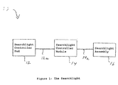
- Figure 1 shows a searchlight generally indicated as 10 according to the present invention, having a search controller 12 (also known herein as a searchlight controller pad), a searchlight controller module 14 and a searchlight assembly 16.
- a search controller 12 also known herein as a searchlight controller pad
- a searchlight controller module 14 also known herein as a searchlight controller pad
- the search controller 12 which is described in greater detail in Figure 2, responds to manual user inputs for controlling the basic operation of the searchlight according to the present invention, including turning the searchlight on/off, moving the searchlight up/down and left/right, moving the searchlight fast/slow, providing SOS signaling and/or one-touch center control, providing spotlight or floodlight functionality, etc., consistent with that shown and described herein, and provides a searchlight controller signal along the line 12a to the searchlight controller module 14 containing information about the manual user inputs for controlling the basic operation of the searchlight.
- the searchlight controller module 14 which is described in greater detail in Figure 3, responds the searchlight controller signal along the line 12a, processes this signal, and provides a searchlight controller module signal along the line 14a to the searchlight assembly 16 containing information about commands for electromechanically controlling the basic operation of the searchlight consistent with that shown and described herein.
- the searchlight assembly 16 which is described in greater detail in Figures 4-5, responds to the searchlight controller module signal along the line 14a and turns the searchlight on/off, moves the searchlight up/down and left/right, fast/slow, provides SOS signaling, provides the one-touch centerline, provides spotlight or floodlight functionality, etc., consistent with that shown and described herein.
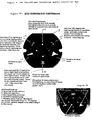
- Figure 2 shows the searchlight controller pad 12 in Figure 1 in greater detail, including a keypad 18 having a 2-speed joystick 20, an SOS key 22, a sweep key 24, a spot mode key 26, a flood mode key 28 and an on/off key 30 for providing for the functionality including turning the searchlight on/off, moving the searchlight up/down and left/right, moving the searchlight fast/slow, providing SOS signaling and centerline, providing spotlight or floodlight functionality, etc.
- the 2-speed joystick 20 moves the searchlight up, down, left, right, and at 45 degrees angle, i.e. 45 degrees to the upper right, upper left, lower right, and lower left.
- the 2-speed joystick 20 provides the searchlight with a two-speed operation, including a slow speed when held for the first 3-5 seconds, a fast speed after 3-5 seconds, and a control resets operation back to slow speed when released by the user or operator.
- the 2-speed joystick 20 allows a searchlight selection of slow and fast speed rotational options to be chosen separately from the spot/flood beam options.
- the "slow speed/spot beam” and “fast speed/flood beam” have historically been linked in function.
- the user or operator of the controller 12 can choose speed and beam pattern separately via the 2-speed joystick 20 and the "spot" and "flood” touch pad buttons or keys 26 or 28.
- the functionality of the 2-speed joystick 20 may be implemented in the 2-speed joystick module 54 in Figure 3, consistent with that discussed below.
- the aforementioned description of the 2-speed joystick 20 is provided by way of example only.
- the scope of the invention is not intended to be limited to any particular length of time or range of time that the user holds the 2-speed joystick to achieve the desired functionality; and embodiments are envisioned in which the 2-speed joystick is held for a different time, such as 1-3 second, 1-4 seconds, 2-4 seconds, etc. to achieve the desired functionality.
- 2-speed joysticks are known in the art and the scope of the invention is not intended to be limited to any particular type or kind thereof either now known or later developed in the future.
- a person skilled in the art would be able to adapt a known 2-speed joystick to implement and perform the functionality shown and described herein.
- the SOS key 22 activates SOS signaling in the current lamp head position after a 2 second hold; a second press activates a 30 degrees incremental rotation and signaling function; and a third press cancels signaling and rotation and the searchlight stays on.
- the functionality of the SOS key 22 may be implemented in the SOS signaling module 56 in Figure 3, consistent with that discussed below.
- the aforementioned description of the SOS key 22 is provided by way of example only.
- the scope of the invention is not intended to be limited to any particular ordering of the functionality of the SOS key 22 when pressed, the length of time pressed or the number of degrees of the rotation.
- embodiment are envisioned having a different ordering of the functionality of the SOS key 22 when pressed, a different length of time pressed, a different number of degrees of the rotation, or some combination thereof.
- the sweep key 24 activates a 20 degrees left/right sweep feature in spot/slow mode and activates motors and lamps/lights if not already on; while a second press deactivates the sweep function and the lamp stays on.
- the aforementioned description of the sweep key 24 is provided by way of example only.
- the scope of the invention is not intended to be limited to any particular ordering of the functionality of the SOS key 24 when pressed, the length of time pressed or the number of degrees of the sweep.
- embodiment are envisioned having a different ordering of the functionality of the sweep key 24 when pressed, a different length of time pressed, a different number of degrees of the sweep, or some combination thereof.
- the spot mode key 26, the flood mode key 28 and the on/off key 30 respectively switch the searchlight to a spot mode, a floodlight mode or power the lamps and motors on/off.
- the on/off key 30 also kills power to lamps and motors. Back lighting may be green when the power is "off" (same as other key or button); and amber with the power "on.” This functionality may be implemented in the modules 60, 62, 64, consistent with that discussed below.
- the on/off key 30 may be pressed and held for 1 second to return the searchlight head to centerline.
- the lamp if the lamp is "on", it will remain on after the light centers; if the light is off, the lamp head will center without activating the lamps; power to the motors will then turn off at the end of the movement.
- the "center home” feature that provides a user or boat owner with a one-touch controller pad function that returns the searchlight 10 to a customary forward pointing/on boat centerline searchlight position after use. This "center home” feature eliminates the need to attempt adjustment to the preferred centerline positioning using a joystick or 8-way touchpad when often the searchlight body cannot be seen by the operator.
- the functionality of the sweep key 24 may be implemented in the module 56 in Figure 3, consistent with that discussed below. However, the scope of the invention is not intended to be limited to implementing the "center home " feature in the "on/off” key 30; embodiments are envisioned in which this feature is implemented in another key, such as the sweep key 24 or some other suitable key.
- FIG. 1 The Searchlight Controller Module 14
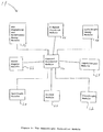
- Figure 3 shows the searchlight controller module 14 in Figure 1 in greater detail, which includes one or modules for performing the functionality shown and described in relation to the searchlight controller pad 12, the corresponding keypad 18, the 2-speed joystick 20, the SOS key 22, the sweep key 24, the spot mode key 26, the flood mode key 28 and the on/off key 30, for providing for the associated functionality including turning the searchlight on/off, moving the searchlight up/down and left/right, moving the searchlight fast/slow, providing SOS signaling, providing spotlight or floodlight functionality, etc.
- the searchlight controller module 14 may include a control processor module 52, a 2-speed joystick module 54, an SOS signaling and rotational sweep module 56, a left/right sweep module 58, a spotlight module 60, a floodlight module 62, an on/off module 64, a power supply module 66, an input/output module 68 for providing signals to/from the searchlight controller pad 12 and the searchlight assembly 16, or some combination.
- the functionality of one or more of the modules shown in Figure 3 may be implemented using hardware, software, firmware, or a combination thereof, although the scope of the invention is not intended to be limited to any particular embodiment thereof.
- the modules would include one or more microprocessor-based architectures having a microprocessor, a random access memory (RAM), a read only memory (ROM), input/output devices and control, data and address buses connecting the same.
- RAM random access memory
- ROM read only memory
- input/output devices control, data and address buses connecting the same.
- a person skilled in the art would be able to program such a microprocessor-based implementation to perform the functionality described herein without undue experimentation.
- the scope of the invention is not intended to be limited to any particular implementation using technology known or later developed in the future.
- the scope of the invention is intended to include the modules being stand alone modules or one or more module having one or more of the aforementioned functionalities in the combination, or in combination with other circuitry (not shown herein) for implementing another module.
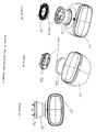
- Figure 4 shows the searchlight assembly 16 in Figure 1 in greater detail, which includes a light assembly generally indicated as 70 and a searchlight up/down and left/right motorized assembly 72 having a mounting gasket 74, as best shown in Figures 4a, 4b, 4c.
- the light assembly 70 includes a head assembly 80 with a main housing 82 for receiving a halogen chassis assembly 84, a lens 86, an O-ring 88 and a ring 88.
- the light assembly 70 is arranged on the motorized assembly 72 in a manner suitable for moving the searchlight up/down and left/right, fast/slow, providing SOS signaling, providing spotlight or floodlight functionality, etc., consistent with that shown and described herein.
- Figure 5 shows the searchlight up/down and left/right motorized assembly 72 in greater detail.
- the searchlight up/down and left/right motorized assembly 72 includes a bottom base 90, a bellows seal 92 and an up/down gear motor 94 arranged on a top base 95 and a head bracket 96 (see also Figure 5), as well as a base rotation bushing 91 and a base thrust bushing 93.
- the up/down gear motor 94 is coupled to the sector gear 97 for providing the up/down movement of the head assembly 80 in response to rotational movement of the tilt motor pinion 99 of the motor 94.
- the motorized assembly 72 also includes a base neck 98, a left/right motor 100, one or more PCB slip rungs 102, a PCB sensor 104 and an encoder tube 106, as well as a stud plate assembly 108 and a motor coupler 109.
- the left/right motor 100 is coupled to the encoder tube 106 for providing the left/right rotational movement of the head assembly 80 in response to rotational movement of a corresponding pinion (not shown) of the motor 100.
- Figures 4 and 5 do not show a wire harness from the searchlight controller module 14 to the searchlight assembly 16 for providing the searchlight controller module signal along the line 14a to the same; however, a person skilled in the art would appreciate how to implement the same consistent with that shown and described herein.
- the searchlight controller module signal along the line 14a may be provided to the gear motor 94 for controlling the up/down movement of the light assembly 70, and the motor 100 for controlling the left/right movement of the light assembly 70.
- the searchlight controller module signal along the line 14a is coupled to a separate controller for the motorized assembly 72, which provides control signals to the motors 94 and 100 for controlling the movement of the light assembly 70.
- the present invention also features a new and bayonet/security locking and mounting system, that includes a base member in the form of the stud plate assembly 108 (Figure 5), a mounting plate 120 (Figure 4d) and at least one locking bolt or mounting member 110.
- the base member 108 is coupled to the motorized assembly 72 and has the at least one mounting member 110 coupled thereto, as shown.
- the mounting plate 120 is for coupling the base 108 to a device (not shown), like to boat or the like, and has at least one aperture 121 for receiving the at least one mounting member 110.
- Each of the at least one locking bolt 110 is coupled through a respective one of the apertures 121, and the at least one locking bolt 110 requiring a special matching locking wrench (not shown) to tighten and loosen the same making theft of the searchlight from the device substantially more difficult.
- the mounting plate 120 may also includes a locking arrangement for coupling to the light to the device.
- the present invention fills a need in the art to provide a that provides ease of installation by the Original Equipment Boat Manufacturers (OEMs) and anti-theft security for the end-user.
- the present invention provides a searchlight having a new and unique bayonet/security locking and mounting system that significantly reduces installation time and time to remove the searchlight for servicing.
- Additional features that may be implemented in the searchlight according to the present invention include the following:
- the power supply module 66 may include circuitry to implement the 12/24 volt operation of the searchlight based on the requirements of the boat that the searchlight is being implement, as well as the reverse polarity protection.
- the power supply module 66 may include a resettable internal fusing.
Landscapes
- Engineering & Computer Science (AREA)
- General Engineering & Computer Science (AREA)
- Mechanical Engineering (AREA)
- Circuit Arrangement For Electric Light Sources In General (AREA)
- Alarm Systems (AREA)
Abstract
Description
- The present invention relates to a searchlight, and more particularly to a searchlight for a watercraft or other suitable vehicle or vessel.
- The present invention provides a new and unique searchlight featuring a controller having a 2-speed joystick and a center home position, a bayonet/security locking and mounting system, or some combination of one or more of these features.
- The controller having the 2-speed joystick allows a searchlight selection of slow and fast rotational options to be chosen separately from spot/flood beam options. For example, the two-speed joystick allows for the searchlight selection of the slow and fast rotational options, while a first separate button or key allows for providing the searchlight selection of a spot beam option, and a second separate button or key allows for providing the searchlight selection of a flood beam option. Embodiments are also envisioned in which one button controls both the spot/flood beam options.
- The "center home" position feature provides a one-touch controller pad that returns the searchlight to its customary forward pointing/on centerline position after use.
- The bayonet mounting/security locking system features a base, a mounting plate and at least one locking bolting. The base is coupled to the light and has at least one mounting member. The mounting plate is for coupling the base to the device such as a boat and has at least one aperture for receiving the at least one mounting member. Each of the at least one locking bolt is coupled to a respective one of the at least one mounting member, the at least one locking bolt requiring a special matching locking wrench to tighten and loosen the same making theft of the light from the device substantially more difficult.
- The drawing includes the following Figures, that are not necessarily drawn to scale:
- Figure 1 is a block diagram of the a search light according to the present invention.
- Figure 2, including Figures 2a and 2b, show diagrams of the search light controller and/or searchlight controller pad shown in Figure 1 according to the present invention.
- Figure 3 shows a block diagram of the searchlight controller module shown in Figure 1 according to the present invention.
- Figure 4, including Figures 4a, 4b, 4c, 4d, are diagrams of the searchlight assembly according to the present invention, including Figures 4d which is an exploded view of the search light assembly.
- Figure 5 is an exploded view of the searchlight up/down and left/right motorized assembly shown, for example, in Figure 4d according to the present invention.
- Figure 1 shows a searchlight generally indicated as 10 according to the present invention, having a search controller 12 (also known herein as a searchlight controller pad), a
searchlight controller module 14 and asearchlight assembly 16. - In operation, the
search controller 12, which is described in greater detail in Figure 2, responds to manual user inputs for controlling the basic operation of the searchlight according to the present invention, including turning the searchlight on/off, moving the searchlight up/down and left/right, moving the searchlight fast/slow, providing SOS signaling and/or one-touch center control, providing spotlight or floodlight functionality, etc., consistent with that shown and described herein, and provides a searchlight controller signal along the line 12a to thesearchlight controller module 14 containing information about the manual user inputs for controlling the basic operation of the searchlight. - The
searchlight controller module 14 which is described in greater detail in Figure 3, responds the searchlight controller signal along the line 12a, processes this signal, and provides a searchlight controller module signal along the line 14a to thesearchlight assembly 16 containing information about commands for electromechanically controlling the basic operation of the searchlight consistent with that shown and described herein. - The
searchlight assembly 16 which is described in greater detail in Figures 4-5, responds to the searchlight controller module signal along the line 14a and turns the searchlight on/off, moves the searchlight up/down and left/right, fast/slow, provides SOS signaling, provides the one-touch centerline, provides spotlight or floodlight functionality, etc., consistent with that shown and described herein. - Figure 2 shows the
searchlight controller pad 12 in Figure 1 in greater detail, including a keypad 18 having a 2-speed joystick 20, an SOS key 22, a sweep key 24, aspot mode key 26, aflood mode key 28 and an on/offkey 30 for providing for the functionality including turning the searchlight on/off, moving the searchlight up/down and left/right, moving the searchlight fast/slow, providing SOS signaling and centerline, providing spotlight or floodlight functionality, etc. - In operation, the 2-
speed joystick 20 moves the searchlight up, down, left, right, and at 45 degrees angle, i.e. 45 degrees to the upper right, upper left, lower right, and lower left. In addition, the 2-speed joystick 20 provides the searchlight with a two-speed operation, including a slow speed when held for the first 3-5 seconds, a fast speed after 3-5 seconds, and a control resets operation back to slow speed when released by the user or operator. In operation, the 2-speed joystick 20 allows a searchlight selection of slow and fast speed rotational options to be chosen separately from the spot/flood beam options. In the prior art, the "slow speed/spot beam" and "fast speed/flood beam" have historically been linked in function. According to the present invention, now the user or operator of thecontroller 12 can choose speed and beam pattern separately via the 2-speed joystick 20 and the "spot" and "flood" touch pad buttons orkeys speed joystick 20 may be implemented in the 2-speed joystick module 54 in Figure 3, consistent with that discussed below. - The aforementioned description of the 2-
speed joystick 20 is provided by way of example only. The scope of the invention is not intended to be limited to any particular length of time or range of time that the user holds the 2-speed joystick to achieve the desired functionality; and embodiments are envisioned in which the 2-speed joystick is held for a different time, such as 1-3 second, 1-4 seconds, 2-4 seconds, etc. to achieve the desired functionality. - Moreover, 2-speed joysticks are known in the art and the scope of the invention is not intended to be limited to any particular type or kind thereof either now known or later developed in the future. In addition, a person skilled in the art would be able to adapt a known 2-speed joystick to implement and perform the functionality shown and described herein.
- In operation, when pressed by the user the SOS key 22 activates SOS signaling in the current lamp head position after a 2 second hold; a second press activates a 30 degrees incremental rotation and signaling function; and a third press cancels signaling and rotation and the searchlight stays on. The functionality of the SOS key 22 may be implemented in the
SOS signaling module 56 in Figure 3, consistent with that discussed below. - The aforementioned description of the SOS key 22 is provided by way of example only. The scope of the invention is not intended to be limited to any particular ordering of the functionality of the SOS key 22 when pressed, the length of time pressed or the number of degrees of the rotation. For example, embodiment are envisioned having a different ordering of the functionality of the SOS key 22 when pressed, a different length of time pressed, a different number of degrees of the rotation, or some combination thereof.
- In operation, when pressed by the user the sweep key 24 activates a 20 degrees left/right sweep feature in spot/slow mode and activates motors and lamps/lights if not already on; while a second press deactivates the sweep function and the lamp stays on.
- The aforementioned description of the sweep key 24 is provided by way of example only. The scope of the invention is not intended to be limited to any particular ordering of the functionality of the SOS key 24 when pressed, the length of time pressed or the number of degrees of the sweep. For example, embodiment are envisioned having a different ordering of the functionality of the sweep key 24 when pressed, a different length of time pressed, a different number of degrees of the sweep, or some combination thereof.
- The
spot mode key 26, theflood mode key 28 and the on/offkey 30 respectively switch the searchlight to a spot mode, a floodlight mode or power the lamps and motors on/off. In addition, the on/offkey 30 also kills power to lamps and motors. Back lighting may be green when the power is "off" (same as other key or button); and amber with the power "on." This functionality may be implemented in themodules - Moreover, the on/off key 30 may be pressed and held for 1 second to return the searchlight head to centerline. In this embodiment, if the lamp is "on", it will remain on after the light centers; if the light is off, the lamp head will center without activating the lamps; power to the motors will then turn off at the end of the movement. In effect, the "center home" feature that provides a user or boat owner with a one-touch controller pad function that returns the
searchlight 10 to a customary forward pointing/on boat centerline searchlight position after use. This "center home" feature eliminates the need to attempt adjustment to the preferred centerline positioning using a joystick or 8-way touchpad when often the searchlight body cannot be seen by the operator. The functionality of the sweep key 24 may be implemented in themodule 56 in Figure 3, consistent with that discussed below. However, the scope of the invention is not intended to be limited to implementing the "center home " feature in the "on/off"key 30; embodiments are envisioned in which this feature is implemented in another key, such as the sweep key 24 or some other suitable key. - Figure 3 shows the
searchlight controller module 14 in Figure 1 in greater detail, which includes one or modules for performing the functionality shown and described in relation to thesearchlight controller pad 12, the corresponding keypad 18, the 2-speed joystick 20, the SOS key 22, the sweep key 24, thespot mode key 26, theflood mode key 28 and the on/offkey 30, for providing for the associated functionality including turning the searchlight on/off, moving the searchlight up/down and left/right, moving the searchlight fast/slow, providing SOS signaling, providing spotlight or floodlight functionality, etc. - By way of example, as shown the
searchlight controller module 14 may include acontrol processor module 52, a 2-speed joystick module 54, an SOS signaling androtational sweep module 56, a left/right sweep module 58, aspotlight module 60, afloodlight module 62, an on/offmodule 64, a power supply module 66, an input/output module 68 for providing signals to/from thesearchlight controller pad 12 and thesearchlight assembly 16, or some combination. - By way of example, the functionality of one or more of the modules shown in Figure 3 may be implemented using hardware, software, firmware, or a combination thereof, although the scope of the invention is not intended to be limited to any particular embodiment thereof. In a typical software implementation, the modules would include one or more microprocessor-based architectures having a microprocessor, a random access memory (RAM), a read only memory (ROM), input/output devices and control, data and address buses connecting the same. A person skilled in the art would be able to program such a microprocessor-based implementation to perform the functionality described herein without undue experimentation. The scope of the invention is not intended to be limited to any particular implementation using technology known or later developed in the future. Moreover, the scope of the invention is intended to include the modules being stand alone modules or one or more module having one or more of the aforementioned functionalities in the combination, or in combination with other circuitry (not shown herein) for implementing another module.
- Figure 4 shows the
searchlight assembly 16 in Figure 1 in greater detail, which includes a light assembly generally indicated as 70 and a searchlight up/down and left/rightmotorized assembly 72 having a mountinggasket 74, as best shown in Figures 4a, 4b, 4c. - As best shown in Figure 4d, the
light assembly 70 includes a head assembly 80 with a main housing 82 for receiving a halogen chassis assembly 84, a lens 86, an O-ring 88 and a ring 88. Thelight assembly 70 is arranged on themotorized assembly 72 in a manner suitable for moving the searchlight up/down and left/right, fast/slow, providing SOS signaling, providing spotlight or floodlight functionality, etc., consistent with that shown and described herein. - Figure 5 shows the searchlight up/down and left/right
motorized assembly 72 in greater detail. - As shown in Figure 5, the searchlight up/down and left/right
motorized assembly 72 includes a bottom base 90, a bellows seal 92 and an up/downgear motor 94 arranged on a top base 95 and a head bracket 96 (see also Figure 5), as well as a base rotation bushing 91 and a base thrust bushing 93. The up/downgear motor 94 is coupled to the sector gear 97 for providing the up/down movement of the head assembly 80 in response to rotational movement of the tilt motor pinion 99 of themotor 94. - The
motorized assembly 72 also includes a base neck 98, a left/right motor 100, one or more PCB slip rungs 102, a PCB sensor 104 and anencoder tube 106, as well as a stud plate assembly 108 and amotor coupler 109. The left/right motor 100 is coupled to theencoder tube 106 for providing the left/right rotational movement of the head assembly 80 in response to rotational movement of a corresponding pinion (not shown) of themotor 100. - The scope of the invention is not intended to be limited to any particular way of arranging the
light assembly 70 on themotorized assembly 72, or moving these elements in relation to one another, in order to implement and/or perform the aforementioned functionality. Moreover, embodiments of the present invention are also envisioned using other ways either known or later developed in the future for arranging a suitable light assembly like 70 on a suitable motorized assembly like 72, or moving such elements in relation to one another to achieve the same. - Finally, Figures 4 and 5 do not show a wire harness from the
searchlight controller module 14 to thesearchlight assembly 16 for providing the searchlight controller module signal along the line 14a to the same; however, a person skilled in the art would appreciate how to implement the same consistent with that shown and described herein. For example, the searchlight controller module signal along the line 14a may be provided to thegear motor 94 for controlling the up/down movement of thelight assembly 70, and themotor 100 for controlling the left/right movement of thelight assembly 70. Embodiments are also envisioned in which the searchlight controller module signal along the line 14a is coupled to a separate controller for themotorized assembly 72, which provides control signals to themotors light assembly 70. - Furthermore, the present invention also features a new and bayonet/security locking and mounting system, that includes a base member in the form of the stud plate assembly 108 (Figure 5), a mounting plate 120 (Figure 4d) and at least one locking bolt or mounting member 110. The base member 108 is coupled to the
motorized assembly 72 and has the at least one mounting member 110 coupled thereto, as shown. The mountingplate 120 is for coupling the base 108 to a device (not shown), like to boat or the like, and has at least oneaperture 121 for receiving the at least one mounting member 110. Each of the at least one locking bolt 110 is coupled through a respective one of theapertures 121, and the at least one locking bolt 110 requiring a special matching locking wrench (not shown) to tighten and loosen the same making theft of the searchlight from the device substantially more difficult. The mountingplate 120 may also includes a locking arrangement for coupling to the light to the device. - The present invention fills a need in the art to provide a that provides ease of installation by the Original Equipment Boat Manufacturers (OEMs) and anti-theft security for the end-user. The present invention provides a searchlight having a new and unique bayonet/security locking and mounting system that significantly reduces installation time and time to remove the searchlight for servicing.
- Additional features that may be implemented in the searchlight according to the present invention include the following:
- 1) Up to two mode stations;
- 2) 12/24 volt operation;
- 3) Reverse polarity protection;
- 4) Resettable internal fusing;
- 5) Rotation speed: Fast 25-30 degrees per second, horizontal; slow 15-20 degrees per second, vertical; and
- 6) The controller may be waterproof.
- The power supply module 66 may include circuitry to implement the 12/24 volt operation of the searchlight based on the requirements of the boat that the searchlight is being implement, as well as the reverse polarity protection. The power supply module 66 may include a resettable internal fusing.
- It should be understood that, unless stated otherwise herein, any of the features, characteristics, alternatives or modifications described regarding a particular embodiment herein may also be applied, used, or incorporated with any other embodiment described herein.
- Although the invention has been described and illustrated with respect to exemplary embodiments thereof, the foregoing and various other additions and omissions may be made therein without departing from the spirit and scope of the present invention.
Claims (11)
- A light, such as a searchlight, for mounting on a device or vehicle, such as a boat, characterized in that
the light has a controller that allows a searchlight selection of slow and fast rotational options to be chosen separately from spot/flood beam options. - A light according to claim 1, wherein the controller includes a two-speed joystick for providing the searchlight selection of the slow and fast rotational options.
- A light according to claim 1 or 2, wherein the controller includes a first button for providing the searchlight selection of a spot beam option.
- A light according to claim 1 or 2, wherein the controller includes a second button for providing the searchlight selection of a flood beam option.
- A light according to claim 1 or 2, wherein the controller includes a first button for providing the searchlight selection of a spot beam option, and includes a second button for providing the searchlight selection of a flood beam option.
- A light according to any of claims 1-5, wherein the controller is a one-touch controller pad that returns the searchlight to the customary forward pointing/on centerline position after use.
- A light, such as floodlight, for mounting on a device or vehicle, such as a boat, characterized in that
the light has a one-touch controller pad that returns the searchlight to the customary forward pointing/on centerline position after use. - A light according to claim 7 comprising a controller according.to any of claims 1-5.
- A light, such as a searchlight or floodlight, for mounting on a device or vehicle, such as a boat, comprising:a base being coupled to the light and having at least one mounting member;a mounting plate for coupling the base to the device, the mounting plate member having at least one aperture for receiving the at least one mounting member;at least one locking bolt, each being coupling to a respective one of the at least one mounting member, the at least one locking bolt requiring a special matching locking wrench to tighten and loosen the same making theft of the light from the device substantially more difficult.
- A light according to claim 9, wherein the mounting plate includes a locking arrangement for coupling to the light to the device.
- A light according to claim 9 or 10, comprising a controller according to any of claims 1-6.
Applications Claiming Priority (1)
| Application Number | Priority Date | Filing Date | Title |
|---|---|---|---|
| US62113604P | 2004-10-22 | 2004-10-22 |
Publications (2)
| Publication Number | Publication Date |
|---|---|
| EP1650078A2 true EP1650078A2 (en) | 2006-04-26 |
| EP1650078A3 EP1650078A3 (en) | 2010-05-19 |
Family
ID=35677493
Family Applications (1)
| Application Number | Title | Priority Date | Filing Date |
|---|---|---|---|
| EP20050023156 Ceased EP1650078A3 (en) | 2004-10-22 | 2005-10-24 | Searchlight featuring bayonet mounting/security system, "Center Home" rotation control system, and joystick for 2-speed rotational operation |
Country Status (2)
| Country | Link |
|---|---|
| US (1) | US7452091B2 (en) |
| EP (1) | EP1650078A3 (en) |
Cited By (4)
| Publication number | Priority date | Publication date | Assignee | Title |
|---|---|---|---|---|
| ES2338841A1 (en) * | 2008-05-27 | 2010-05-12 | Federal Signal Vama, S.A. | Orientation device for focus seekers and/or television cameras (Machine-translation by Google Translate, not legally binding) |
| US8118452B2 (en) | 2008-09-11 | 2012-02-21 | Itt Manufacturing Enterprises, Inc. | Searchlight having rotational beam focus for marine applications |
| EP2719580A1 (en) * | 2012-10-11 | 2014-04-16 | Volkswagen Aktiengesellschaft | Searchlight for special vehicles |
| EP3012151A1 (en) * | 2014-10-20 | 2016-04-27 | Goodrich Lighting Systems GmbH | Helicopter search light |
Families Citing this family (7)
| Publication number | Priority date | Publication date | Assignee | Title |
|---|---|---|---|---|
| US20080175016A1 (en) * | 2007-01-19 | 2008-07-24 | Shih Hsiung Wu | Illumination device for vehicle |
| US7862197B2 (en) | 2008-09-12 | 2011-01-04 | Golight, Inc. | Searchlight with flexible attachment means |
| US8201974B1 (en) | 2009-03-09 | 2012-06-19 | Whelen Engineering Company, Inc. | Pan-tilt spotlight |
| US8672515B2 (en) | 2010-11-15 | 2014-03-18 | Power Products, Llc | Marine spotlight |
| US9789808B1 (en) | 2016-07-01 | 2017-10-17 | Toyota Motor Engineering & Manufacturing North America, Inc. | Headlight directional control for illuminating an identified object |
| CN209146980U (en) | 2017-09-25 | 2019-07-23 | 米沃奇电动工具公司 | Lamp assembly |
| US11192494B2 (en) | 2020-02-07 | 2021-12-07 | Honeywell International Inc. | Systems and methods for search and landing light |
Citations (3)
| Publication number | Priority date | Publication date | Assignee | Title |
|---|---|---|---|---|
| US4712167A (en) | 1986-06-30 | 1987-12-08 | Mycro Group Co. | Remote control, moveable lighting system |
| WO2000006941A1 (en) | 1998-07-31 | 2000-02-10 | Code 3, Inc. | Spotlight assembly |
| US6786622B1 (en) | 2000-09-08 | 2004-09-07 | Itt Manufacturing Enterprises, Inc. | Searchlight and controller therefore |
Family Cites Families (17)
| Publication number | Priority date | Publication date | Assignee | Title |
|---|---|---|---|---|
| US5228770A (en) * | 1989-05-12 | 1993-07-20 | Brunson Robert L | Search light |
| ES2017176A6 (en) | 1989-09-13 | 1991-01-01 | Astral Sa | Countercurrent installation for swimming pools. |
| US5347664A (en) | 1990-06-20 | 1994-09-20 | Kdi American Products, Inc. | Suction fitting with pump control device |
| US5167041A (en) | 1990-06-20 | 1992-12-01 | Kdi American Products, Inc. | Suction fitting with pump control device |
| US5499406A (en) | 1994-12-12 | 1996-03-19 | Hydrabaths, Inc. | Safety suction assembly for use in whirlpool baths and the like |
| DE29605085U1 (en) * | 1995-03-31 | 1996-07-04 | Horizont Gerätewerk GmbH, 34497 Korbach | Warning light |
| US5664874A (en) * | 1995-12-29 | 1997-09-09 | Winterer; Allen G. | Barricade warning light |
| JP3417201B2 (en) | 1996-04-19 | 2003-06-16 | 松下電器産業株式会社 | Protection circuit and signal processing LSI |
| US5978981A (en) | 1996-07-15 | 1999-11-09 | Nelson; John | Hair control device for spas |
| US5677669A (en) * | 1996-08-13 | 1997-10-14 | Applied Electro Mechanics, Inc. | Audio illuminator |
| US5725359A (en) | 1996-10-16 | 1998-03-10 | B&S Plastics, Inc. | Pool pump controller |
| US5799339A (en) | 1996-10-17 | 1998-09-01 | American Products | Safety cover for spa suction drain |
| IT1296329B1 (en) | 1997-09-25 | 1999-06-25 | Domino Spa | SUCTION NOZZLE FOR WHIRLPOOL BATHS OR SIMILAR |
| US6038712A (en) | 1997-10-08 | 2000-03-21 | Hydrabaths, Inc. | Safety suction assembly for use in whirlpool baths and the like |
| US6760931B1 (en) | 2002-08-02 | 2004-07-13 | Roy W. Mattson, Jr. | Non-electric sanitation water vessel system |
| US6770194B1 (en) | 2003-01-10 | 2004-08-03 | Aquaria, Inc. | Water overflow device and water return device |
| US8552842B2 (en) * | 2003-12-29 | 2013-10-08 | Xylem Ip Holdings Llc | RF wireless permanently mounted searchlight |
-
2005
- 2005-10-21 US US11/255,591 patent/US7452091B2/en not_active Expired - Lifetime
- 2005-10-24 EP EP20050023156 patent/EP1650078A3/en not_active Ceased
Patent Citations (3)
| Publication number | Priority date | Publication date | Assignee | Title |
|---|---|---|---|---|
| US4712167A (en) | 1986-06-30 | 1987-12-08 | Mycro Group Co. | Remote control, moveable lighting system |
| WO2000006941A1 (en) | 1998-07-31 | 2000-02-10 | Code 3, Inc. | Spotlight assembly |
| US6786622B1 (en) | 2000-09-08 | 2004-09-07 | Itt Manufacturing Enterprises, Inc. | Searchlight and controller therefore |
Cited By (8)
| Publication number | Priority date | Publication date | Assignee | Title |
|---|---|---|---|---|
| ES2338841A1 (en) * | 2008-05-27 | 2010-05-12 | Federal Signal Vama, S.A. | Orientation device for focus seekers and/or television cameras (Machine-translation by Google Translate, not legally binding) |
| ES2338841B1 (en) * | 2008-05-27 | 2011-02-10 | Federal Signal Vama, S.A. | GUIDING DEVICE FOR SEARCH FOCUSES AND / OR TELEVISION CAMERAS. |
| US8118452B2 (en) | 2008-09-11 | 2012-02-21 | Itt Manufacturing Enterprises, Inc. | Searchlight having rotational beam focus for marine applications |
| US8297806B2 (en) | 2008-09-11 | 2012-10-30 | Xylem Ip Holdings Llc | Searchlight having pull-in bezel retention for marine applications |
| EP2719580A1 (en) * | 2012-10-11 | 2014-04-16 | Volkswagen Aktiengesellschaft | Searchlight for special vehicles |
| DE102012019942B4 (en) * | 2012-10-11 | 2016-12-15 | Volkswagen Aktiengesellschaft | Searchlight for special vehicles |
| EP3012151A1 (en) * | 2014-10-20 | 2016-04-27 | Goodrich Lighting Systems GmbH | Helicopter search light |
| US9884691B2 (en) | 2014-10-20 | 2018-02-06 | Goodrich Lighting Systems Gmbh | Helicopter search light |
Also Published As
| Publication number | Publication date |
|---|---|
| US7452091B2 (en) | 2008-11-18 |
| EP1650078A3 (en) | 2010-05-19 |
| US20080019116A1 (en) | 2008-01-24 |
Similar Documents
| Publication | Publication Date | Title |
|---|---|---|
| US7452091B2 (en) | Searchlight featuring bayonet mounting system with 2-speed joystick rotational operation | |
| US5195813A (en) | Wireless control for auxiliary lighting | |
| US20180118097A1 (en) | Light bar for releasably mounting multiple light modules | |
| US20150035435A1 (en) | Light switch unit for controlling exterior lighting of a motor vehicle | |
| KR100253602B1 (en) | Engine starter | |
| US5067055A (en) | Automobile headlamp and rotatable sidelamp of integrated construction and switching circuit for operating same | |
| US12122287B1 (en) | Low-profile LED headlight having a strobe and headlight assembly | |
| US6713896B1 (en) | Method and apparatus for switching several electric circuits | |
| JPS60148732A (en) | Winker device | |
| CN210554503U (en) | A device for integrating rearview mirror adjustment switch and rearview mirror reversing host | |
| KR100613553B1 (en) | Outside mirror with puddle lamp and directional lamp | |
| KR100214300B1 (en) | Voice turnning device in an alarm | |
| JPS632750A (en) | Electronic combination switch | |
| EP1697174B1 (en) | Switch arrangement | |
| CN200974503Y (en) | Automobile leftward-rightward steering front lamp illuminating supplementary | |
| US20050010348A1 (en) | Machine providing for an advanced headlamp system with peripheral beam technology | |
| US3462570A (en) | Vehicle direction signaling and hazard warning switching apparatus | |
| JPH02212234A (en) | Rearview mirror with illumination for vehicle | |
| KR0117320Y1 (en) | Direction lamp for a car | |
| JPH0581473U (en) | Door lock monitor device | |
| KR200389839Y1 (en) | Automatic control system for the rear lamp in a industrial vehicle | |
| AU651538B1 (en) | Wireless control for auxillary lighting | |
| JP2517486B2 (en) | Headlight irradiation angle adjustment device | |
| KR200145444Y1 (en) | Room lamp of a car | |
| KR101870303B1 (en) | An infrared ray light controller |
Legal Events
| Date | Code | Title | Description |
|---|---|---|---|
| PUAI | Public reference made under article 153(3) epc to a published international application that has entered the european phase |
Free format text: ORIGINAL CODE: 0009012 |
|
| AK | Designated contracting states |
Kind code of ref document: A2 Designated state(s): AT BE BG CH CY CZ DE DK EE ES FI FR GB GR HU IE IS IT LI LT LU LV MC NL PL PT RO SE SI SK TR |
|
| AX | Request for extension of the european patent |
Extension state: AL BA HR MK YU |
|
| RIN1 | Information on inventor provided before grant (corrected) |
Inventor name: PARENT, THOMAS G. Inventor name: GORDON, JOSEPH M. Inventor name: BOYD, STEPHEN B. Inventor name: LEBLANC, KENNETH J. |
|
| RAP1 | Party data changed (applicant data changed or rights of an application transferred) |
Owner name: ITT MANUFACTURING ENTERPRISES, INC. |
|
| PUAL | Search report despatched |
Free format text: ORIGINAL CODE: 0009013 |
|
| AK | Designated contracting states |
Kind code of ref document: A3 Designated state(s): AT BE BG CH CY CZ DE DK EE ES FI FR GB GR HU IE IS IT LI LT LU LV MC NL PL PT RO SE SI SK TR |
|
| AX | Request for extension of the european patent |
Extension state: AL BA HR MK YU |
|
| 17P | Request for examination filed |
Effective date: 20101119 |
|
| AKX | Designation fees paid |
Designated state(s): AT BE BG CH CY CZ DE DK EE ES FI FR GB GR HU IE IS IT LI LT LU LV MC NL PL PT RO SE SI SK TR |
|
| 17Q | First examination report despatched |
Effective date: 20110414 |
|
| STAA | Information on the status of an ep patent application or granted ep patent |
Free format text: STATUS: THE APPLICATION HAS BEEN REFUSED |
|
| 18R | Application refused |
Effective date: 20151009 |