EP1650038A1 - Data processing apparatus having a construction for guiding a recording medium - Google Patents
Data processing apparatus having a construction for guiding a recording medium Download PDFInfo
- Publication number
- EP1650038A1 EP1650038A1 EP05021458A EP05021458A EP1650038A1 EP 1650038 A1 EP1650038 A1 EP 1650038A1 EP 05021458 A EP05021458 A EP 05021458A EP 05021458 A EP05021458 A EP 05021458A EP 1650038 A1 EP1650038 A1 EP 1650038A1
- Authority
- EP
- European Patent Office
- Prior art keywords
- opening
- unit
- guide member
- auxiliary guide
- paper
- Prior art date
- Legal status (The legal status is an assumption and is not a legal conclusion. Google has not performed a legal analysis and makes no representation as to the accuracy of the status listed.)
- Granted
Links
- 238000010276 construction Methods 0.000 title abstract description 3
- 238000000034 method Methods 0.000 description 2
- 230000000295 complement effect Effects 0.000 description 1
- 230000001419 dependent effect Effects 0.000 description 1
- 238000007599 discharging Methods 0.000 description 1
- 230000002452 interceptive effect Effects 0.000 description 1
- 238000000926 separation method Methods 0.000 description 1
- 230000001131 transforming effect Effects 0.000 description 1
Images






Classifications
-
- B—PERFORMING OPERATIONS; TRANSPORTING
- B41—PRINTING; LINING MACHINES; TYPEWRITERS; STAMPS
- B41J—TYPEWRITERS; SELECTIVE PRINTING MECHANISMS, i.e. MECHANISMS PRINTING OTHERWISE THAN FROM A FORME; CORRECTION OF TYPOGRAPHICAL ERRORS
- B41J11/00—Devices or arrangements of selective printing mechanisms, e.g. ink-jet printers or thermal printers, for supporting or handling copy material in sheet or web form
- B41J11/006—Means for preventing paper jams or for facilitating their removal
-
- B—PERFORMING OPERATIONS; TRANSPORTING
- B41—PRINTING; LINING MACHINES; TYPEWRITERS; STAMPS
- B41J—TYPEWRITERS; SELECTIVE PRINTING MECHANISMS, i.e. MECHANISMS PRINTING OTHERWISE THAN FROM A FORME; CORRECTION OF TYPOGRAPHICAL ERRORS
- B41J13/00—Devices or arrangements of selective printing mechanisms, e.g. ink-jet printers or thermal printers, specially adapted for supporting or handling copy material in short lengths, e.g. sheets
- B41J13/10—Sheet holders, retainers, movable guides, or stationary guides
- B41J13/103—Sheet holders, retainers, movable guides, or stationary guides for the sheet feeding section
Definitions
- the present invention relates to a data processing apparatus having a transportation unit defining a transportation passage curved in an arc shape, and a pair of paper transportation rollers, which nip and convey paper or similar recording medium delivered from the curved transportation passage to a processing position, disposed at a position separated a specific distance from the output end of the transportation unit.
- a printer connected to a personal computer for example, is used below as an example of a data processing apparatus according to the present invention.
- a transportation mechanism for conveying paper as a transported recording medium from a paper tray, cassette, or other storage unit, one sheet at a time, along a specific transportation path, a recording unit disposed at some intermediate position along the transportation path for recording text, graphics, or other images on the conveyed paper, and various operating devices such as a recording unit drive mechanism for imparting a specific motion to the recording unit as needed for printing.
- some printers have both a paper feed unit and a discharge unit for discharging the printed paper rendered to feed and discharge the paper from openings at the front of the printer.
- This type of printer typically has a paper cassette used to store a supply of paper disposed at the bottom front part of the printer housing, and a discharge tray for the printed paper disposed above the paper cassette.
- a substantially U-shaped transportation path connecting the paper cassette to the discharge tray is rendered inside the housing, and the recording unit is disposed at this U-shaped transportation path.
- the U-shaped transportation path inside the housing is composed of the curved passage of the transportation unit, a paper feed roller pair, and a discharge transportation mechanism.
- the transportation unit has the curved passage that starts from the paper cassette, and is composed of an intermediate roller unit and a guide portion that curves around the roller unit.
- the paper feed roller pair is located a specific distance from the output end of the curved transportation passage.
- the discharge transportation mechanism guides the paper past the recording unit, which is located downstream from the paper feed roller pair, to the discharge tray at the front of the printer.
- JP 2003-154693 A teaches a contact release mechanism for separating the rollers of the transportation unit from the paper when a paper jam occurs. This contact release mechanism releases the roller pressure on the paper when the jammed end of the paper is held to extract the paper from the paper supply or paper discharge side so that the paper can be easily removed.
- JP 2529261 B teaches an arrangement for exposing the curved transportation passage for access from the outside by pivoting the guide portion of the curved transportation passage between an open and a closed state in conjunction with the external cover of the housing in order to facilitate removing jammed paper that is stuck inside the printer due to a paper jam in the U-shaped transportation path.
- a recording medium such as paper
- the data processing apparatus can reliably convey the recording medium between the curved transportation passage and the paper feed roller pair. Furthermore, because the auxiliary guide member retracts away from the paper feed roller pair in conjunction with the unlocking action of the opening/closing levers unlocking the lock unit, the auxiliary guide member can swing to open the guide unit without interference with other components inside the housing, and the curved transportation passage can be exposed to the outside for access. As a result, if by some chance the transported recording medium becomes jammed inside, the guide unit can be opened and the recording medium removed as easily as when the auxiliary guide member is not present.
- the auxiliary guide member preferably advances and retracts in the direction of said paper feed roller pair in conjunction with movement between the unlocked sate and the locked state of the lock unit.
- the auxiliary guide member When the lock unit is engaged in the locked position with the guide unit in the closed position, the auxiliary guide member is positioned in conjunction with this movement from the discharge end of the curved transportation passage to a position projecting to the paper feed roller pair.
- the recording medium can be reliably and consistently guided from the curved transportation passage to the paper feed roller pair.
- the auxiliary guide linking mechanism of this data processing apparatus has a first rack which moves linearly in conjunction with an unlocking operation of said opening/closing levers; a first pinion which meshes with said first rack and rotates in conjunction with linear movement of said first rack; a second pinion which rotates codirectionally to said first pinion; and a second rack which has teeth which mesh with said second pinion arrayed in the retracting direction of said auxiliary guide member, and retracts said auxiliary guide member as a result of linear motion of said second rack in conjunction with rotation of said second pinion.
- the data processing apparatus can freely adjust the linear distance of second rack movement.
- the linear distance of the auxiliary guide member's movement can be set freely without being restricted by the amount of movement of the opening/closing levers needed for locking and unlocking, and an auxiliary guide member that projects the required sufficient length can be smoothly advanced and retracted.
- this data processing apparatus also has stops which contact said opening/closing levers in said unlocked position when said guide unit is in said open position, and hold said lock unit in said unlocked position.
- the lock unit is held in the unlocked position by the stops when the guide unit is closed until the guide unit reaches the normal closed position.
- the auxiliary guide member can be held in the retracted position without operating the opening/closing levers, and the guide unit can be returned to the closed position without the auxiliary guide member striking other members.
- the lock unit of this data processing apparatus is elastically urged toward said locked position.
- the guide unit can thus be reliably held in the closed position during normal operation of the data processing apparatus because the lock unit is always positioned in the locked position except when it is unlocked by the opening/closing levers. Furthermore, if the guide unit is returned to the closed position when these stops are present, the lock unit is disengaged from the stops, the lock unit automatically returns to the locking position, and the guide unit is fixed in the closed position. As a result, the action of closing the guide unit is greatly simplified.
- the auxiliary guide member of this data processing apparatus is housed in a flange member which moves circularly in conjunction with said outside wall portion when said auxiliary guide member retracts away from said paper feed roller pair.
- the data processing apparatus thus arranged prevents the auxiliary guide member from contacting and damaging other parts of the apparatus because the guide unit opens and closes with the auxiliary guide member housed inside the flange member.
- a data processing apparatus thus has an auxiliary guide member for guiding a recording medium conveyed from a curved transportation passage to a paper feed roller pair.
- the recording medium can thus be reliably conveyed between the curved transportation passage and paper feed roller pair.
- the auxiliary guide member retracts away from the paper feed roller pair in conjunction with releasing a lock unit by means of opening/closing levers. Opening the guide unit thus exposes the curved transportation passage to the outside, thereby enabling jammed transported media to be easily removed.
- a data processing apparatus 1 is a front loading, front discharge type of business printer.
- a box-like paper cassette 9 for holding paper as the recording medium can be freely installed to and removed from the front of the center area of the printer case 7.
- the printer case 7 is composed of a bottom case 3 and a top case 5.
- a discharge tray 11 for receiving printed paper is disposed covering the open top portion of the paper cassette 9.
- a display unit 13 for displaying the operating status, for example, and an operating panel 14 are disposed on both sides at the front of the printer case 7.
- a paper supply mechanism 21, a transportation unit 23, a paper feed roller pair 25 and 26, a recording unit 29, and a discharge transportation mechanism 31 assembled inside the printer case 7.
- the paper supply mechanism 21 supplies paper P stored in the paper cassette 9, one sheet at a time, into the transportation path.
- the transportation unit 23 defines a curved transportation passage for the paper P and conveys the paper P supplied from the paper supply mechanism 21 through the curved transportation passage toward the paper feed roller pair, and the paper feed roller pair 25 and 26 then nip and feed the paper P from the transportation unit 23 to the processing position.
- the recording unit 29 records text, graphics, or other images on the paper P at a flat portion of the transportation path downstream from the paper feed roller pair 25 and 26.
- the discharge transportation mechanism 31 then discharges the paper P after printing by the recording unit 29 is finished onto the discharge tray 11 at the front of the case.
- the paper feed roller pair 25 and 26 includes a drive roller 25 and a complementary or pressure roller 26.
- the paper cassette 9, transportation unit 23, paper feed roller pair 25 and 26, discharge transportation mechanism 31, and discharge tray 11 inside the printer case 7 constitute a U-shaped transportation path for conveying paper P delivered from the paper cassette 9 at the bottom front, one sheet at a time, to the back of the printer, for changing the direction of paper transportation, and then for conveying the paper P back to the front of the printer.
- the paper supply mechanism 21 is arranged to turn up and down as seen in the figures by pivoting on a support pin 35 disposed at the back end of a frame 34, which has a pickup roller 33 at its distal end for delivering paper.
- the pickup roller 33 of this paper supply mechanism 21 can thus be placed in contact with the topmost sheet of paper P in the paper cassette 9 as a result of the frame 34 swinging up and down.
- the paper supply mechanism 21 is held with the frame 34 horizontal as shown in Fig. 3, and the pickup roller 33 is held separated from the paper P in the paper cassette 9.
- the frame 34 swings down pivoting on the support pin 35 so that the pickup roller 33 is pressed against the paper P in the paper cassette 9 as shown in Fig. 4. Rotation of the pickup roller 33 then pushes the paper P in the paper cassette 9 against the inclined separation pad 36, thus feeding one sheet at a time toward the transportation unit 23 as the top sheet of paper P is separated from the stack by friction and the stiffness of the paper P.
- the frame 34 returns to the horizontal position as shown in Fig. 5.
- the transportation unit 23 has a guide unit 38 and an intermediate roller 39.
- the guide unit 38 is disposed on the outer side of the transportation path (that is, on the side toward the back of the printer 1) and has an arc-shaped guide surface 37.
- the intermediate roller 39 is disposed on the inner side of the transportation path (that is, toward the front of the printer 1 relative to the guide unit 38) and conveys the paper P from the bottom to the top of the guide unit 38.
- a curved transportation passage as part of the U-shaped transportation path is formed between the intermediate roller 39 and guide unit 38.
- a retard roller 22 is disposed at the bottom of the guide unit 38 and an assist roller 24 is disposed at the top.
- Paper P delivered by the pickup roller 33 is nipped and conveyed by the intermediate roller 39 and retard roller 22, and then nipped and conveyed by the intermediate roller 39 and assist roller 24.
- the paper P is thus conveyed through the curved transportation passage, and the leading end of the paper is directed toward the front of the printer to the straight portion of the U-shaped transportation path.
- the paper feed roller pair 25 and 26 is disposed separated a specific distance from the output end of the curved transportation passage (the downstream or discharge end of the transportation unit 23) towards the front of the printer, and as shown in Fig. 5 holds and conveys the paper P delivered to the substantially straight portion of the transportation path from the transportation unit 23 to the processing position below the recording unit 29.
- the outside wall part at the back of the printer case 7 located behind the guide unit 38 is an opening/closing cover 16 which can be opened and closed by an unlocking/locking operation of a pair of sliding opening/closing levers 41 and 42.
- the guide unit 38 is integrally formed with the inside of this opening/closing cover 16. As a result, opening the opening/closing cover 16 also exposes the curved transportation path to the outside.
- the opening/closing cover 16 has a curved back wall 16a and substantially crescent-shaped side walls 16b integrally formed on opposite ends with the back wall 16a.
- a support pin 16c protrudes to the outside from the bottom of each side wall 16b.
- These support pins 16c fit and pivot freely in matching portions of the printer case 7, and thus connect the opening/closing cover 16 to the printer case 7 so that the opening/closing cover 16 can swing around the support 16c pin with its outer end describing a sector of a radius R1.
- An eave-like shelf 16e is formed integrally with the opening/closing cover 16 projecting toward the inside the case as shown in Fig. 7.
- the opening/closing levers 41 and 42 attached to the opening/closing cover 16 are composed of slide guides 41 a, 42a, levers 41 b, 42b, and a spring (not shown in the figure) urging the levers 41 b, 42b in opposite directions.
- the slide guides 41 a, 42a are installed at the inner surface of the opening/closing cover 16, and support the levers 41 b, 42b so that the levers 41 b, 42b can slide linearly in the direction widthwise to the case as indicated by arrows A and B in Fig. 6 and Fig. 7.
- Levers 45 and 46, and locking pins 47 and 48 are formed integrally with the opening/closing levers 41 and 42.
- the levers 45 and 46 protrude externally from a lever operating opening 16d formed in the opening/closing cover 16 as shown in Fig. 6.
- the locking pins 47 and 48 project to the outside from the side walls 16b as shown in Fig. 8 and fit into matching holes formed in the printer case 7 when the opening/closing cover 16 is closed.
- the opening/closing cover 16 When the outside ends of the locking pins 47 and 48 are inserted to these holes in the printer case 7, the opening/closing cover 16 is locked in its closed state and cannot be opened unless the locking is released. Because the force of the spring not shown urges the locking pins 47 and 48 into the locked position, the locking pins 47 and 48 remain in the locked position unless the levers 45 and 46 are operated to disengage the lock. The opening/closing cover 16 is thus reliably held in the closed position during normal operation of the printer 1.
- the pair of levers 45 and 46 protruding from the lever operating opening 16d in the opening/closing cover 16 are spaced apart from each other by a distance L as shown in Fig. 8 when the locking pins 47 and 48 are in the locked position.
- the locking pins 47 and 48 slide against the force of the spring toward the inside in directions same as that of arrows A and B, i.e., widthwise to the printer.
- the guide unit 38 has a guide base 38a which is fixed to the inner surface of the opening/closing cover 16, and a plurality of ribs 38b protruding from the guide base 38a are arranged with a specific interval between each other across the width of the printer.
- the curved surface formed at the top end of each rib 38b forms the curved guide surface 37.
- an auxiliary guide member 51 is also disposed at the guide unit 38.
- This auxiliary guide member 51 projects from the discharge end of the guide surface 37 toward the paper feed roller pair 25 and 26 with the weight of the auxiliary guide member 51 pushing down the paper P being conveyed toward the paper feed roller pair 25 and 26, thereby preventing the paper P from becoming skewed or lifting up.
- this auxiliary guide member 51 has a comb-like construction with a plurality of fingers 51 a for preventing the paper P from lifting up. The fingers are arrayed across the width of the printer with an appropriate distance between the fingers 51 a.
- the printer 1 also has an auxiliary guide linking mechanism 53 for moving the auxiliary guide member 51 to and away from the paper feed roller pair 25 and 26 in conjunction with locking and unlocking the opening/closing levers 41 and 42, and retracting the auxiliary guide member 51 from the paper feed roller pair 25 and 26 when the opening/closing levers 41 and 42 are unlocked.
- This auxiliary guide linking mechanism 53 is composed of a first rack and pinion unit 55 and a second rack and pinion unit 57.
- the first rack and pinion unit 55 is composed of a first rack 61 and a pair of first pinions 63.
- the rack 61 slides in conjunction with the sliding action of the opening/closing lever 41 when the opening/closing levers 41 and 42 are locked and unlocked.
- the first pinions 63 mesh with the first rack 61 and are rotated by movement of the first rack 61.
- the first rack 61 is formed integrally with the lever 41 b of opening/closing lever 41.
- the second rack and pinion unit 57 is composed of a pair of second pinions 65 and a corresponding pair of second racks 67.
- the second pinions 65 are formed coaxially to and rotate in unison with the first pinions 63.
- Each second rack 67 has teeth which mesh with a corresponding one of the second pinions 65.
- the teeth are arrayed in the advancing/retracting direction of auxiliary guide member 51 so that the linear movement of the second racks 67 accompanying rotation of the second pinions 65 contributes to the advancing/retracting movement of the auxiliary guide member 51.
- the second racks 67 are arranged at a right angle to the direction of first rack's 61 movement, and rotation of the second pinions 65 thus causes the second racks 67 to move linearly perpendicularly to the direction of first rack's 61 movement.
- the rack and pinion units together represent motion transforming means used to change the direction of a linear motion from a first direction to a second direction that is orthogonal to the first direction.
- the arc described by the distal end of the auxiliary guide member 51 has a radius R3 from the support pins 16c. If the auxiliary guide member 51 moves circularly on support pins 16c at this time, the distal end of the auxiliary guide member 51 will not interfere with the support mechanism 70 for the pressure roller 26, and the opening/closing cover 16 can be opened completely. Furthermore, because the auxiliary guide member 51 is housed inside (below) the shelf 16e in this retracted position, the distal end of the auxiliary guide member 51 is prevented from contacting and damaging other parts inside the printer.
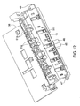
- Fig. 12 is an perspective view showing the opening/closing levers 41 and 42 unlocked and the opening/closing cover 16 partially open
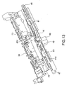
- Fig. 13 is an perspective view showing the first rack 61 of the first rack and pinion unit 55 exposed by removing the auxiliary guide member 51 from the guide unit 38 on the back of the opening/closing cover 16 shown in Fig. 12.
- stops 73 are disposed at a fixed position at the bottom back end of the printer case 7.
- the opening/closing levers 41 and 42 slide to the unlocked position with their ends 41d, 42d caught by these stops 73 when the opening/closing cover 16 is opened.
- These stops 73 are fixed walls formed at the back end part of the printer case 7 opposite the bottom edge of the opening/closing cover 16.
- the auxiliary guide member 51 advances to the paper feed roller pair 25 and 26 in conjunction with movement of the auxiliary guide linking mechanism 53 from the unlocked to the locked position of the locking pins 47 and 48. More specifically, when the locking pins 47 and 48 move to the locked position when the opening/closing cover 16 closes, the auxiliary guide member 51 moves therewith from the outlet end of the transportation unit 23 and is automatically positioned projecting toward the paper feed roller pair 25 and 26. As a result, when the opening/closing cover 16 is closed and the printer 1 is driven to transport the paper P, the paper P fed from the transportation unit 23 by the paper feed roller pair 25 and 26 is always guided by the auxiliary guide member 51.
- the printer 1 of the present embodiment can reliably feed the paper P between the transportation unit 23 and paper feed roller pair 25 and 26 with high precision and stability.
- auxiliary guide member 51 is attached to the guide unit 38, which is attached to the inside of the opening/closing cover 16 of the printer case 7, a mechanism dedicated to supporting the auxiliary guide member 51 need not be rendered on the printer case 7 side. As a result, the assembly process is not complicated by an increase in parts needed to assemble the auxiliary guide member 51 to the printer case 7.
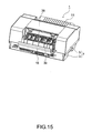
- the paper jam can be exposed by unlocking the opening/closing levers 41 and 42 and opening the opening/closing cover 16 and the guide unit 38 as shown in Fig. 15.
- the auxiliary guide member 51 retracts inside the guide unit 38 in conjunction with operation of the opening/closing levers 41 and 42 when the opening/closing levers 41 and 42 are unlocked, the projection of the auxiliary guide member 51 from the guide unit 38 to the paper feed roller pair 25 and 26 side is reduced as shown in Fig. 11.
- the auxiliary guide member 51 is also housed inside the shelf 16e and protected from contact with other parts.
- the auxiliary guide member 51 is thus prevented from interfering with the neighboring support mechanism 70 when the opening/closing cover 16 and guide unit 38 open and close, the layout of other components inside the printer case 7 is not restricted by the need to avoid interference with the auxiliary guide member 51, and the opening/closing mechanism of the guide unit 38 can be easily incorporated.
- the opening/closing levers 41 and 42 are unlocked to correct a paper jam in the printer 1 according to this embodiment of the invention and the opening/closing cover 16 starts to open, the ends 41 d, 42d of the opening/closing levers 41 and 42 are locked in the unlocked position by the stops 73 on the printer case 7.
- the opening/closing levers 41 and 42 thus are held in the unlocked position even after the user releases the opening/closing levers 41 and 42, thus making opening and closing the opening/closing cover 16 easier.
- the auxiliary guide member 51 is held in the retracted position when the opening/closing cover 16 is open, the auxiliary guide member 51 does not interfere with removing jammed paper P.
- the opening/closing cover 16 when the opening/closing cover 16 is closed after removing jammed paper P, the locking pins 47 and 48 are held in the unlocked position by the stops 73 until the opening/closing cover 16 returns to the normal closed position.
- the opening/closing cover 16 can therefore be returned to the fully closed position without operating the opening/closing levers 41 and 42 and without the auxiliary guide member 51 striking other members.
- the length of the linear movement of the second racks 67 can be desirably adjusted in the foregoing printer 1 by adjusting the gear ratio between the first pinions 63 and second pinions 65.
- the linear distance of auxiliary guide member 51 movement can thus be desirably set without being limited by the distance the opening/closing levers 41 and 42 must move to lock and unlock, and an auxiliary guide member 51 that projects the necessary sufficient distance can be smoothly advanced and retracted.
- the first rack 61 is formed integrally with the opening/closing lever 41, a separate part functioning as the auxiliary guide linking mechanism 53 for advancing and retracting the auxiliary guide member 51 can be omitted by forming the second racks 67 integrally with the auxiliary guide member 51, for example.
- the number of parts to be assembled can thus be reduced, and the assembly process can be simplified.
- the present invention can be applied to data processing apparatuses other than a printer like that described above as an example, such as a photocopier, a fax machine, a money changing machine, a ticket-issuing machine, or any other type of apparatus having a similarly U-shaped transportation path or a complex transportation path having a plurality of curved transportation portions for conveying transported media, in particular paper or similar recording media like OHP sheets.
- data processing apparatuses other than a printer like that described above as an example, such as a photocopier, a fax machine, a money changing machine, a ticket-issuing machine, or any other type of apparatus having a similarly U-shaped transportation path or a complex transportation path having a plurality of curved transportation portions for conveying transported media, in particular paper or similar recording media like OHP sheets.
Landscapes
- Delivering By Means Of Belts And Rollers (AREA)
- Unwinding Webs (AREA)
- Feeding Of Articles By Means Other Than Belts Or Rollers (AREA)
- Sheets, Magazines, And Separation Thereof (AREA)
Abstract
Description
- The present invention relates to a data processing apparatus having a transportation unit defining a transportation passage curved in an arc shape, and a pair of paper transportation rollers, which nip and convey paper or similar recording medium delivered from the curved transportation passage to a processing position, disposed at a position separated a specific distance from the output end of the transportation unit.
- A printer connected to a personal computer, for example, is used below as an example of a data processing apparatus according to the present invention.
- Inside the housing which provides the external appearance of a printer are disposed a transportation mechanism for conveying paper as a transported recording medium from a paper tray, cassette, or other storage unit, one sheet at a time, along a specific transportation path, a recording unit disposed at some intermediate position along the transportation path for recording text, graphics, or other images on the conveyed paper, and various operating devices such as a recording unit drive mechanism for imparting a specific motion to the recording unit as needed for printing.
- In order to reduce the footprint and the size of the printer, some printers have both a paper feed unit and a discharge unit for discharging the printed paper rendered to feed and discharge the paper from openings at the front of the printer. This type of printer typically has a paper cassette used to store a supply of paper disposed at the bottom front part of the printer housing, and a discharge tray for the printed paper disposed above the paper cassette. A substantially U-shaped transportation path connecting the paper cassette to the discharge tray is rendered inside the housing, and the recording unit is disposed at this U-shaped transportation path.
- The U-shaped transportation path inside the housing is composed of the curved passage of the transportation unit, a paper feed roller pair, and a discharge transportation mechanism. The transportation unit has the curved passage that starts from the paper cassette, and is composed of an intermediate roller unit and a guide portion that curves around the roller unit. The paper feed roller pair is located a specific distance from the output end of the curved transportation passage. The discharge transportation mechanism guides the paper past the recording unit, which is located downstream from the paper feed roller pair, to the discharge tray at the front of the printer.
- A problem with this arrangement is that paper jams occur easily inside the transportation unit and in the area from the curved transportation passage to the paper feed roller pair due to skewing and curling in the leading end of the paper. To avoid this problem, JP 2003-154693 A teaches a contact release mechanism for separating the rollers of the transportation unit from the paper when a paper jam occurs. This contact release mechanism releases the roller pressure on the paper when the jammed end of the paper is held to extract the paper from the paper supply or paper discharge side so that the paper can be easily removed.
- In addition, JP 2529261 B teaches an arrangement for exposing the curved transportation passage for access from the outside by pivoting the guide portion of the curved transportation passage between an open and a closed state in conjunction with the external cover of the housing in order to facilitate removing jammed paper that is stuck inside the printer due to a paper jam in the U-shaped transportation path.
- In order to prevent paper jams in the U-shaped transportation path described above, the curling and skewing at the leading end of the paper that cause paper jams must be prevented between the curved transportation passage and the paper feed roller pair. However, if the guide portion of the transportation unit that guides the paper between the curved transportation passage and the paper feed roller pair is extended to the paper feed roller pair, opening the guide portion of the transportation unit when a paper jam occurs interferes with other members inside the housing, and it is thus difficult to expose the curved transportation passage for access from outside the housing.
- It is an object of the present invention to provide a data processing apparatus having a structure for guiding a recording medium, such as paper, from a curved transportation passage to a paper feed roller pair and for allowing the curved transportation passage to be easily made accessible by opening a closable guide unit, thus affording highly stable transportation through a U-shaped transportation path and easy removal of a recording medium jammed inside the transportation path.
- This object is achieved by a data processing apparatus as claimed in
claim 1. Preferred embodiments of the invention are subject-matter of the dependent claims. - As a result of having an auxiliary guide member to guide the recording medium conveyed from the curved transportation passage to the paper feed roller pair, the data processing apparatus according to the invention can reliably convey the recording medium between the curved transportation passage and the paper feed roller pair. Furthermore, because the auxiliary guide member retracts away from the paper feed roller pair in conjunction with the unlocking action of the opening/closing levers unlocking the lock unit, the auxiliary guide member can swing to open the guide unit without interference with other components inside the housing, and the curved transportation passage can be exposed to the outside for access. As a result, if by some chance the transported recording medium becomes jammed inside, the guide unit can be opened and the recording medium removed as easily as when the auxiliary guide member is not present.
- The auxiliary guide member preferably advances and retracts in the direction of said paper feed roller pair in conjunction with movement between the unlocked sate and the locked state of the lock unit.
- When the lock unit is engaged in the locked position with the guide unit in the closed position, the auxiliary guide member is positioned in conjunction with this movement from the discharge end of the curved transportation passage to a position projecting to the paper feed roller pair. As a result, when the data processing apparatus is driven to convey the recording medium, the recording medium can be reliably and consistently guided from the curved transportation passage to the paper feed roller pair.
- Yet further preferably, the auxiliary guide linking mechanism of this data processing apparatus has a first rack which moves linearly in conjunction with an unlocking operation of said opening/closing levers; a first pinion which meshes with said first rack and rotates in conjunction with linear movement of said first rack; a second pinion which rotates codirectionally to said first pinion; and a second rack which has teeth which mesh with said second pinion arrayed in the retracting direction of said auxiliary guide member, and retracts said auxiliary guide member as a result of linear motion of said second rack in conjunction with rotation of said second pinion.
- By changing the gear ratio of the first pinion and second pinion, the data processing apparatus according to this aspect of the invention can freely adjust the linear distance of second rack movement. As a result, the linear distance of the auxiliary guide member's movement can be set freely without being restricted by the amount of movement of the opening/closing levers needed for locking and unlocking, and an auxiliary guide member that projects the required sufficient length can be smoothly advanced and retracted.
- Yet further preferably, this data processing apparatus also has stops which contact said opening/closing levers in said unlocked position when said guide unit is in said open position, and hold said lock unit in said unlocked position.
- When the opening/closing levers are unlocked and the guide unit starts to open in order to remove a recording medium stuck inside this data processing apparatus, one end of the lock units is held in the unlocked position by the stops. The opening/closing levers are thus held in the unlocked (released) position even after the opening/closing levers are released by the hand that unlocked the levers, and the guide unit can thus be easily opened and closed. Furthermore, because the auxiliary guide member is held in the retracted position when the guide unit is open, the auxiliary guide member does not interfere with removing the jammed recording medium.
- Furthermore, after a stuck recording medium is removed, the lock unit is held in the unlocked position by the stops when the guide unit is closed until the guide unit reaches the normal closed position. As a result, the auxiliary guide member can be held in the retracted position without operating the opening/closing levers, and the guide unit can be returned to the closed position without the auxiliary guide member striking other members.
- Yet further preferably, the lock unit of this data processing apparatus is elastically urged toward said locked position.
- The guide unit can thus be reliably held in the closed position during normal operation of the data processing apparatus because the lock unit is always positioned in the locked position except when it is unlocked by the opening/closing levers. Furthermore, if the guide unit is returned to the closed position when these stops are present, the lock unit is disengaged from the stops, the lock unit automatically returns to the locking position, and the guide unit is fixed in the closed position. As a result, the action of closing the guide unit is greatly simplified.
- Yet further preferably, the auxiliary guide member of this data processing apparatus is housed in a flange member which moves circularly in conjunction with said outside wall portion when said auxiliary guide member retracts away from said paper feed roller pair.
- The data processing apparatus thus arranged prevents the auxiliary guide member from contacting and damaging other parts of the apparatus because the guide unit opens and closes with the auxiliary guide member housed inside the flange member.
- A data processing apparatus according to the present invention thus has an auxiliary guide member for guiding a recording medium conveyed from a curved transportation passage to a paper feed roller pair. The recording medium can thus be reliably conveyed between the curved transportation passage and paper feed roller pair. Furthermore, the auxiliary guide member retracts away from the paper feed roller pair in conjunction with releasing a lock unit by means of opening/closing levers. Opening the guide unit thus exposes the curved transportation passage to the outside, thereby enabling jammed transported media to be easily removed.
- Other objects and attainments together with a fuller understanding of the invention will become apparent and appreciated by referring to the following description of preferred embodiments taken in conjunction with the accompanying drawings, in which:
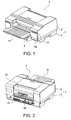
- Fig. 1
- is an perspective view from above the front of a data processing apparatus according to the present invention;
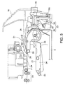
- Fig. 2
- is an perspective view from above the back of a data processing apparatus according to the present invention;
- Fig. 3
- is a side sectional view showing the paper supply mechanism when the data processing apparatus shown in Fig. 1 is at rest;
- Fig. 4
- is a side sectional view showing the paper supply mechanism of the data processing apparatus shown in Fig. 1 when feeding paper;
- Fig. 5
- is a side sectional view showing the data processing apparatus shown in Fig. 1 during printing;
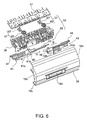
- Fig. 6
- is an perspective exploded view from the back of the opening/closing cover and guide unit shown in Fig. 3;
- Fig. 7
- is an perspective exploded view from the front of the opening/closing cover and guide unit shown in Fig. 3;
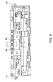
- Fig. 8
- is a front view showing the opening/closing levers of the guide unit shown in Fig. 3 in the locked position;
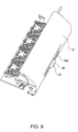
- Fig. 9
- is an perspective view from the back of the opening/closing cover when the opening/closing levers of the data processing apparatus shown in Fig. 2 are in the unlocked position;
- Fig. 10
- is a front view showing the opening/closing levers of the guide unit shown in Fig. 3 in the unlocked position;
- Fig. 11
- is a side sectional view showing the auxiliary guide member in the retracted position when the opening/closing levers of the data processing apparatus shown in Fig. 1 are in the unlocked position;
- Fig. 12
- is an perspective view showing the opening/closing cover of the data processing apparatus shown in Fig. 2 in the partially open position;
- Fig. 13
- is an perspective view showing the rack of the first rack and pinion exposed by removing the auxiliary guide member from the opening/closing cover shown in Fig. 12;
- Fig. 14
- is an perspective view from above the back of the printer case showing the stops for locking the opening/closing levers in the unlocked position; and
- Fig. 15
- is an perspective view showing the opening/closing cover of the data processing apparatus shown in Fig. 2 open.
- A
data processing apparatus 1 according to an embodiment of the invention is a front loading, front discharge type of business printer. As shown in Fig. 1, a box-like paper cassette 9 for holding paper as the recording medium can be freely installed to and removed from the front of the center area of theprinter case 7. Theprinter case 7 is composed of abottom case 3 and atop case 5. Adischarge tray 11 for receiving printed paper is disposed covering the open top portion of thepaper cassette 9. Adisplay unit 13 for displaying the operating status, for example, and anoperating panel 14 are disposed on both sides at the front of theprinter case 7. - As shown in Fig. 3 to Fig. 5, a
paper supply mechanism 21, atransportation unit 23, a paperfeed roller pair recording unit 29, and adischarge transportation mechanism 31 assembled inside theprinter case 7. - The
paper supply mechanism 21 supplies paper P stored in thepaper cassette 9, one sheet at a time, into the transportation path. Thetransportation unit 23 defines a curved transportation passage for the paper P and conveys the paper P supplied from thepaper supply mechanism 21 through the curved transportation passage toward the paper feed roller pair, and the paperfeed roller pair transportation unit 23 to the processing position. Therecording unit 29 records text, graphics, or other images on the paper P at a flat portion of the transportation path downstream from the paperfeed roller pair discharge transportation mechanism 31 then discharges the paper P after printing by therecording unit 29 is finished onto thedischarge tray 11 at the front of the case. - Note that the paper
feed roller pair drive roller 25 and a complementary orpressure roller 26. - The
paper cassette 9,transportation unit 23, paperfeed roller pair discharge transportation mechanism 31, and dischargetray 11 inside theprinter case 7 constitute a U-shaped transportation path for conveying paper P delivered from thepaper cassette 9 at the bottom front, one sheet at a time, to the back of the printer, for changing the direction of paper transportation, and then for conveying the paper P back to the front of the printer. - The
paper supply mechanism 21 is arranged to turn up and down as seen in the figures by pivoting on asupport pin 35 disposed at the back end of aframe 34, which has apickup roller 33 at its distal end for delivering paper. Thepickup roller 33 of thispaper supply mechanism 21 can thus be placed in contact with the topmost sheet of paper P in thepaper cassette 9 as a result of theframe 34 swinging up and down. When theprinter 1 is at rest, thepaper supply mechanism 21 is held with theframe 34 horizontal as shown in Fig. 3, and thepickup roller 33 is held separated from the paper P in thepaper cassette 9. - When paper is to be fed into the
printer 1, theframe 34 swings down pivoting on thesupport pin 35 so that thepickup roller 33 is pressed against the paper P in thepaper cassette 9 as shown in Fig. 4. Rotation of thepickup roller 33 then pushes the paper P in thepaper cassette 9 against theinclined separation pad 36, thus feeding one sheet at a time toward thetransportation unit 23 as the top sheet of paper P is separated from the stack by friction and the stiffness of the paper P. When paper feeding is completed and therecording unit 29 starts printing, theframe 34 returns to the horizontal position as shown in Fig. 5. - As shown in Fig. 3 to Fig. 5, the
transportation unit 23 has aguide unit 38 and anintermediate roller 39. Theguide unit 38 is disposed on the outer side of the transportation path (that is, on the side toward the back of the printer 1) and has an arc-shapedguide surface 37. Theintermediate roller 39 is disposed on the inner side of the transportation path (that is, toward the front of theprinter 1 relative to the guide unit 38) and conveys the paper P from the bottom to the top of theguide unit 38. - Hence, a curved transportation passage as part of the U-shaped transportation path is formed between the
intermediate roller 39 and guideunit 38. - A
retard roller 22 is disposed at the bottom of theguide unit 38 and anassist roller 24 is disposed at the top. Paper P delivered by thepickup roller 33 is nipped and conveyed by theintermediate roller 39 andretard roller 22, and then nipped and conveyed by theintermediate roller 39 and assistroller 24. The paper P is thus conveyed through the curved transportation passage, and the leading end of the paper is directed toward the front of the printer to the straight portion of the U-shaped transportation path. - The paper
feed roller pair transportation unit 23 to the processing position below therecording unit 29. - As shown in Fig. 2 to Fig. 6, the outside wall part at the back of the
printer case 7 located behind theguide unit 38 is an opening/closing cover 16 which can be opened and closed by an unlocking/locking operation of a pair of sliding opening/closing levers 41 and 42. Theguide unit 38 is integrally formed with the inside of this opening/closing cover 16. As a result, opening the opening/closing cover 16 also exposes the curved transportation path to the outside. - The arrangement enabling the opening/
closing cover 16 to open and close, and theguide unit 38 being attached to or forming part of the opening/closing cover 16, are further described below. - As shown in Fig. 6, the opening/
closing cover 16 has acurved back wall 16a and substantially crescent-shapedside walls 16b integrally formed on opposite ends with theback wall 16a. Asupport pin 16c protrudes to the outside from the bottom of eachside wall 16b. - These support pins 16c fit and pivot freely in matching portions of the
printer case 7, and thus connect the opening/closing cover 16 to theprinter case 7 so that the opening/closing cover 16 can swing around thesupport 16c pin with its outer end describing a sector of a radius R1. An eave-like shelf 16e is formed integrally with the opening/closing cover 16 projecting toward the inside the case as shown in Fig. 7. - As shown in Fig. 6 and Fig. 7, the opening/closing levers 41 and 42 attached to the opening/
closing cover 16 are composed of slide guides 41 a, 42a, levers 41 b, 42b, and a spring (not shown in the figure) urging thelevers closing cover 16, and support thelevers levers -
Levers pins levers lever operating opening 16d formed in the opening/closing cover 16 as shown in Fig. 6. The locking pins 47 and 48 project to the outside from theside walls 16b as shown in Fig. 8 and fit into matching holes formed in theprinter case 7 when the opening/closing cover 16 is closed. - When the outside ends of the locking pins 47 and 48 are inserted to these holes in the
printer case 7, the opening/closing cover 16 is locked in its closed state and cannot be opened unless the locking is released. Because the force of the spring not shown urges the locking pins 47 and 48 into the locked position, the locking pins 47 and 48 remain in the locked position unless thelevers closing cover 16 is thus reliably held in the closed position during normal operation of theprinter 1. - The pair of
levers lever operating opening 16d in the opening/closing cover 16 are spaced apart from each other by a distance L as shown in Fig. 8 when the locking pins 47 and 48 are in the locked position. When pressure is then applied to the outside surfaces of thelevers levers - When the
levers closing cover 16. The locking pins 47 and 48 thus completely disengage from the matching lock holes in theprinter case 7, and are unlocked from theprinter case 7. Once thus unlocked, the opening/closing cover 16 can open to the rear. - As shown in Fig. 7, the
guide unit 38 has aguide base 38a which is fixed to the inner surface of the opening/closing cover 16, and a plurality ofribs 38b protruding from theguide base 38a are arranged with a specific interval between each other across the width of the printer. The curved surface formed at the top end of eachrib 38b forms thecurved guide surface 37. - As shown in Fig. 5 to Fig. 7, an
auxiliary guide member 51 is also disposed at theguide unit 38. Thisauxiliary guide member 51 projects from the discharge end of theguide surface 37 toward the paperfeed roller pair auxiliary guide member 51 pushing down the paper P being conveyed toward the paperfeed roller pair auxiliary guide member 51 has a comb-like construction with a plurality offingers 51 a for preventing the paper P from lifting up. The fingers are arrayed across the width of the printer with an appropriate distance between thefingers 51 a. - The
printer 1 according to this embodiment of the invention also has an auxiliaryguide linking mechanism 53 for moving theauxiliary guide member 51 to and away from the paperfeed roller pair auxiliary guide member 51 from the paperfeed roller pair - This auxiliary
guide linking mechanism 53 is composed of a first rack andpinion unit 55 and a second rack andpinion unit 57. - As shown in Fig. 7, the first rack and
pinion unit 55 is composed of afirst rack 61 and a pair of first pinions 63. Therack 61 slides in conjunction with the sliding action of the opening/closinglever 41 when the opening/closing levers 41 and 42 are locked and unlocked. The first pinions 63 mesh with thefirst rack 61 and are rotated by movement of thefirst rack 61. Thefirst rack 61 is formed integrally with thelever 41 b of opening/closinglever 41. - The second rack and
pinion unit 57 is composed of a pair ofsecond pinions 65 and a corresponding pair ofsecond racks 67. The second pinions 65 are formed coaxially to and rotate in unison with the first pinions 63. Eachsecond rack 67 has teeth which mesh with a corresponding one of the second pinions 65. The teeth are arrayed in the advancing/retracting direction ofauxiliary guide member 51 so that the linear movement of thesecond racks 67 accompanying rotation of the second pinions 65 contributes to the advancing/retracting movement of theauxiliary guide member 51. The second racks 67 are arranged at a right angle to the direction of first rack's 61 movement, and rotation of thesecond pinions 65 thus causes thesecond racks 67 to move linearly perpendicularly to the direction of first rack's 61 movement. As will be understood, the rack and pinion units together represent motion transforming means used to change the direction of a linear motion from a first direction to a second direction that is orthogonal to the first direction. - When the
levers auxiliary guide member 51 aroundsupport pins 16c is R2 as shown in Fig. 3. If the opening/closing cover 16 is opened pivoting onsupport pins 16c at this time, the distal end of theauxiliary guide member 51 will interfere with thesupport mechanism 70 supportingpressure roller 26. This applies to the case theauxiliary guide member 51 is not retracted by auxiliaryguide linking mechanism 53. - However, if the
levers auxiliary guide member 51 is retracted from the paperfeed roller pair guide linking mechanism 53, the arc described by the distal end of theauxiliary guide member 51 has a radius R3 from the support pins 16c. If theauxiliary guide member 51 moves circularly onsupport pins 16c at this time, the distal end of theauxiliary guide member 51 will not interfere with thesupport mechanism 70 for thepressure roller 26, and the opening/closing cover 16 can be opened completely. Furthermore, because theauxiliary guide member 51 is housed inside (below) theshelf 16e in this retracted position, the distal end of theauxiliary guide member 51 is prevented from contacting and damaging other parts inside the printer. - Fig. 12 is an perspective view showing the opening/closing levers 41 and 42 unlocked and the opening/
closing cover 16 partially open, and Fig. 13 is an perspective view showing thefirst rack 61 of the first rack andpinion unit 55 exposed by removing theauxiliary guide member 51 from theguide unit 38 on the back of the opening/closing cover 16 shown in Fig. 12. - As shown in Fig. 13 and Fig. 14, stops 73 are disposed at a fixed position at the bottom back end of the
printer case 7. When the opening/closing levers 41 and 42 are unlocked to open the opening/closing cover 16, the opening/closing levers 41 and 42 slide to the unlocked position with theirends stops 73 when the opening/closing cover 16 is opened. These stops 73 are fixed walls formed at the back end part of theprinter case 7 opposite the bottom edge of the opening/closing cover 16. - When the opening/
closing cover 16 closes, the ends 41 d, 42d of the opening/closing levers 41 and 42 separate from thestops 73, which then do no longer interfere with locking and unlocking the opening/closing levers 41 and 42. - During this closing movement the
auxiliary guide member 51 advances to the paperfeed roller pair guide linking mechanism 53 from the unlocked to the locked position of the locking pins 47 and 48. More specifically, when the locking pins 47 and 48 move to the locked position when the opening/closing cover 16 closes, theauxiliary guide member 51 moves therewith from the outlet end of thetransportation unit 23 and is automatically positioned projecting toward the paperfeed roller pair closing cover 16 is closed and theprinter 1 is driven to transport the paper P, the paper P fed from thetransportation unit 23 by the paperfeed roller pair auxiliary guide member 51. - Because the
auxiliary guide member 51 prevents the paper P from skewing or lifting from the transportation path on its way from the curved transportation passage to the paperfeed roller pair printer 1 of the present embodiment can reliably feed the paper P between thetransportation unit 23 and paperfeed roller pair - Furthermore, because the
auxiliary guide member 51 is attached to theguide unit 38, which is attached to the inside of the opening/closing cover 16 of theprinter case 7, a mechanism dedicated to supporting theauxiliary guide member 51 need not be rendered on theprinter case 7 side. As a result, the assembly process is not complicated by an increase in parts needed to assemble theauxiliary guide member 51 to theprinter case 7. - Furthermore, if a paper jam occurs inside or near the curved transportation passage, the paper jam can be exposed by unlocking the opening/closing levers 41 and 42 and opening the opening/
closing cover 16 and theguide unit 38 as shown in Fig. 15. In addition, because theauxiliary guide member 51 retracts inside theguide unit 38 in conjunction with operation of the opening/closing levers 41 and 42 when the opening/closing levers 41 and 42 are unlocked, the projection of theauxiliary guide member 51 from theguide unit 38 to the paperfeed roller pair auxiliary guide member 51 is also housed inside theshelf 16e and protected from contact with other parts. Theauxiliary guide member 51 is thus prevented from interfering with the neighboringsupport mechanism 70 when the opening/closing cover 16 and guideunit 38 open and close, the layout of other components inside theprinter case 7 is not restricted by the need to avoid interference with theauxiliary guide member 51, and the opening/closing mechanism of theguide unit 38 can be easily incorporated. - Furthermore, because the area where paper jams are likely to occur inside the printer can be exposed by opening the opening/closing cover 16 (see Fig. 15), jammed paper can be accessed directly by the user when a paper jam occurs. The paper P can thus be easily removed and the paper quickly corrected.
- Furthermore, when the opening/closing levers 41 and 42 are unlocked to correct a paper jam in the
printer 1 according to this embodiment of the invention and the opening/closing cover 16 starts to open, the ends 41 d, 42d of the opening/closing levers 41 and 42 are locked in the unlocked position by thestops 73 on theprinter case 7. The opening/closing levers 41 and 42 thus are held in the unlocked position even after the user releases the opening/closing levers 41 and 42, thus making opening and closing the opening/closing cover 16 easier. Furthermore, because theauxiliary guide member 51 is held in the retracted position when the opening/closing cover 16 is open, theauxiliary guide member 51 does not interfere with removing jammed paper P. - Yet further, when the opening/
closing cover 16 is closed after removing jammed paper P, the locking pins 47 and 48 are held in the unlocked position by thestops 73 until the opening/closing cover 16 returns to the normal closed position. The opening/closing cover 16 can therefore be returned to the fully closed position without operating the opening/closing levers 41 and 42 and without theauxiliary guide member 51 striking other members. - In addition, when the opening/
closing cover 16 returns to the closed position and the opening/closing levers 41 and 42 disengage from thestops 73, the force of the spring automatically moves the opening/closing levers 41 and 42 to the locked position, thereby securing the opening/closing cover 16 to theprinter case 7. In other words, closing the opening/closing cover 16 is also quite simple. - The length of the linear movement of the
second racks 67 can be desirably adjusted in the foregoingprinter 1 by adjusting the gear ratio between thefirst pinions 63 andsecond pinions 65. The linear distance ofauxiliary guide member 51 movement can thus be desirably set without being limited by the distance the opening/closing levers 41 and 42 must move to lock and unlock, and anauxiliary guide member 51 that projects the necessary sufficient distance can be smoothly advanced and retracted. - Furthermore, because the
first rack 61 is formed integrally with the opening/closinglever 41, a separate part functioning as the auxiliaryguide linking mechanism 53 for advancing and retracting theauxiliary guide member 51 can be omitted by forming thesecond racks 67 integrally with theauxiliary guide member 51, for example. The number of parts to be assembled can thus be reduced, and the assembly process can be simplified. - The present invention can be applied to data processing apparatuses other than a printer like that described above as an example, such as a photocopier, a fax machine, a money changing machine, a ticket-issuing machine, or any other type of apparatus having a similarly U-shaped transportation path or a complex transportation path having a plurality of curved transportation portions for conveying transported media, in particular paper or similar recording media like OHP sheets.
Claims (6)
- A data processing apparatus comprising
a case (7),
a transportation path defined inside the case (7) adapted to guide a recording medium (P) through the case (7) to and past a processing position,
a transportation unit (23) having an intermediate roller (39) and a guide unit (38) with an arc-shaped guide surface (37), the intermediate roller (39) and the guide surface (37) defining a substantially arc-shaped transportation passage with an entrance end and a discharge end, the transportation passage forming a part of the transportation path, said guide unit (38) being arranged to pivot between an open position and a closed position in unison with an outside wall portion (16) of said case (7);
a feed roller pair (25, 26) disposed at a distance from the discharge end of said transportation passage and adapted to nip and convey the recording medium (P) exiting the transportation passage toward the processing position;
a lock unit (47, 48) having a locked state and an unlocked state and being arranged, to lock, in its locked state, said guide unit (38) in said closed position and allow, in its unlocked state, the guide unit (38) to pivot to said open position; and
opening/closing levers (41, 42) for locking and unlocking the lock unit (47, 48);
wherein said guide unit (38) comprises an auxiliary guide member (51) arranged to project, in a first position, from the discharge end of the transportation passage toward the paper feed roller pair (25, 26) so as to guide the recording medium (P) conveyed toward said paper feed roller pair (25, 26), and
a linking mechanism (53) is provided for retracting said auxiliary guide member (51) from said first position in a direction separating from said paper feed roller pair (25, 26) to a second position in conjunction with an unlocking operation of said lock unit (47, 48) by said opening/closing levers (41, 42). - The apparatus described in claim 1, wherein said auxiliary guide member (51) and said linking mechanism (53) are arranged such that said auxiliary guide member (51) is linearily movable between a first position advanced toward said paper feed roller pair (25, 26) and a second position retracted from said feed roller pair (25, 26), the auxiliary guide member (51) being movable in conjunction with said lock unit (47, 48) being switched between said unlocked position and said locked position.
- The apparatus described in claim 1 or 2, wherein said linking mechanism (53) comprises:a first rack (61) which is adapted to move linearly in conjunction with an unlocking operation of said opening/closing levers (41, 42);a first pinion (63) which meshes with said first rack (61) and to rotate in conjunction with a linear movement of said first rack (61);a second pinion (65) which is arranged to rotate codirectionally to said first pinion (63); anda second rack (67) which meshes with said second pinion (65), the teeth of the second rack (67) being arrayed in the moving direction of said auxiliary guide member (51) between said first and said second position, and the second rack (67) being arranged to move said auxiliary guide member (51) as a result of a rotation of said second pinion (65).
- The apparatus described in any of claims 1 to 3, further comprising stops (73) arranged to be contacted by said opening/closing levers (41, 42) in said unlocked state of the lock unit (47, 48) when said guide unit (38) is in said open position, so as to hold said lock unit (47, 48) in said unlocked state.
- The apparatus described in any of claims 1 to 4, wherein said lock unit (47, 48) is elastically urged toward said locked state.
- The apparatus described in any of claims 1 to 5, wherein said auxiliary guide member (51) is housed in a flange member (16e) which is arranged to pivot in conjunction with said outside wall portion (16) when said auxiliary guide member (51) is retracted from said paper feed roller pair (25, 26).
Applications Claiming Priority (1)
| Application Number | Priority Date | Filing Date | Title |
|---|---|---|---|
| JP2004303855 | 2004-10-19 |
Publications (2)
| Publication Number | Publication Date |
|---|---|
| EP1650038A1 true EP1650038A1 (en) | 2006-04-26 |
| EP1650038B1 EP1650038B1 (en) | 2008-05-28 |
Family
ID=35587834
Family Applications (1)
| Application Number | Title | Priority Date | Filing Date |
|---|---|---|---|
| EP05021458A Expired - Lifetime EP1650038B1 (en) | 2004-10-19 | 2005-09-30 | Data processing apparatus having a construction for guiding a recording medium |
Country Status (4)
| Country | Link |
|---|---|
| US (1) | US7364156B2 (en) |
| EP (1) | EP1650038B1 (en) |
| CN (1) | CN100491219C (en) |
| DE (1) | DE602005007143D1 (en) |
Families Citing this family (3)
| Publication number | Priority date | Publication date | Assignee | Title |
|---|---|---|---|---|
| US20080099980A1 (en) | 2006-10-26 | 2008-05-01 | Seiko Epson Corporation | Sheet media feeding device, sheet media separation method, and sheet media processing device |
| JP5126517B2 (en) * | 2008-05-19 | 2013-01-23 | セイコーエプソン株式会社 | Feeding device, recording device |
| CN107531065B (en) * | 2015-07-31 | 2019-06-11 | 惠普发展公司有限责任合伙企业 | Stopping operation of image forming apparatus |
Citations (3)
| Publication number | Priority date | Publication date | Assignee | Title |
|---|---|---|---|---|
| JPS63286860A (en) * | 1987-05-19 | 1988-11-24 | Fujitsu Ltd | Paper carrying device |
| JP2003154693A (en) | 2001-11-22 | 2003-05-27 | Brother Ind Ltd | Printer device |
| US20030151653A1 (en) * | 2002-02-08 | 2003-08-14 | Matsushita Electric Industrial Co., Ltd. | Ink-jet recording device and control method thereof |
Family Cites Families (9)
| Publication number | Priority date | Publication date | Assignee | Title |
|---|---|---|---|---|
| JPH09325543A (en) * | 1996-05-31 | 1997-12-16 | Mita Ind Co Ltd | Image forming device |
| JP3534150B2 (en) | 1997-04-09 | 2004-06-07 | セイコーエプソン株式会社 | Paper feeder |
| JP3760597B2 (en) | 1997-10-02 | 2006-03-29 | 村田機械株式会社 | Open / close cover mechanism of automatic document feeder |
| JP3760598B2 (en) | 1997-10-02 | 2006-03-29 | 村田機械株式会社 | Document feeder |
| JP2003201041A (en) | 2002-01-10 | 2003-07-15 | Murata Mach Ltd | Paper conveying device |
| US6829453B2 (en) * | 2003-03-04 | 2004-12-07 | Kabushiki Kaisha Toshiba | Carrying apparatus and image forming apparatus including same in which the relative positioning of carrying rollers is automatically adjusted |
| JP3870919B2 (en) * | 2003-03-20 | 2007-01-24 | ブラザー工業株式会社 | Image forming apparatus |
| US7435025B2 (en) * | 2004-03-05 | 2008-10-14 | Brother Kogyo Kabushiki Kaisha | Image recording apparatus |
| US7448621B2 (en) * | 2004-03-29 | 2008-11-11 | Canon Kabushiki Kaisha | Sheet conveying apparatus and image forming apparatus |
-
2005
- 2005-09-30 EP EP05021458A patent/EP1650038B1/en not_active Expired - Lifetime
- 2005-09-30 DE DE602005007143T patent/DE602005007143D1/en not_active Expired - Lifetime
- 2005-10-10 CN CNB2005101085879A patent/CN100491219C/en not_active Expired - Fee Related
- 2005-10-14 US US11/251,050 patent/US7364156B2/en not_active Expired - Fee Related
Patent Citations (4)
| Publication number | Priority date | Publication date | Assignee | Title |
|---|---|---|---|---|
| JPS63286860A (en) * | 1987-05-19 | 1988-11-24 | Fujitsu Ltd | Paper carrying device |
| JP2529261B2 (en) | 1987-05-19 | 1996-08-28 | 富士通株式会社 | Paper transport device |
| JP2003154693A (en) | 2001-11-22 | 2003-05-27 | Brother Ind Ltd | Printer device |
| US20030151653A1 (en) * | 2002-02-08 | 2003-08-14 | Matsushita Electric Industrial Co., Ltd. | Ink-jet recording device and control method thereof |
Non-Patent Citations (1)
| Title |
|---|
| PATENT ABSTRACTS OF JAPAN vol. 013, no. 108 (P - 843) 15 March 1989 (1989-03-15) * |
Also Published As
| Publication number | Publication date |
|---|---|
| US7364156B2 (en) | 2008-04-29 |
| US20060082050A1 (en) | 2006-04-20 |
| DE602005007143D1 (en) | 2008-07-10 |
| EP1650038B1 (en) | 2008-05-28 |
| CN1765719A (en) | 2006-05-03 |
| CN100491219C (en) | 2009-05-27 |
Similar Documents
| Publication | Publication Date | Title |
|---|---|---|
| US7823877B2 (en) | Transportation device and image processing apparatus | |
| JP5473393B2 (en) | Image forming apparatus | |
| JP3371770B2 (en) | Image forming device | |
| JP2020121866A (en) | Medium ejecting device and image reading device | |
| EP1650038B1 (en) | Data processing apparatus having a construction for guiding a recording medium | |
| JP4831140B2 (en) | Sheet holding tray and image forming apparatus | |
| JP6489957B2 (en) | Printing device and sheet cassette | |
| JP4353079B2 (en) | Information processing device | |
| JP4640179B2 (en) | Information processing device | |
| JP5787550B2 (en) | Containment device | |
| JP4640036B2 (en) | Information processing device | |
| US12252372B2 (en) | Medium transport apparatus | |
| JP4501661B2 (en) | Information processing device | |
| JP2005141111A (en) | Image forming apparatus | |
| JP5499571B2 (en) | Paper feeder | |
| JP7667647B2 (en) | Recording device | |
| JPH10250894A (en) | Paper discharge tray | |
| JP2003131450A (en) | Image forming device | |
| JP7610385B2 (en) | Recording device | |
| JPH07232842A (en) | Image forming device | |
| JP2025150444A (en) | Medium transport device and recording device | |
| JP3493767B2 (en) | Image forming device | |
| JP4420700B2 (en) | Image forming apparatus | |
| JP2003262996A (en) | Copying machine and composite machine | |
| JP3092574B2 (en) | Printing device |
Legal Events
| Date | Code | Title | Description |
|---|---|---|---|
| PUAI | Public reference made under article 153(3) epc to a published international application that has entered the european phase |
Free format text: ORIGINAL CODE: 0009012 |
|
| AK | Designated contracting states |
Kind code of ref document: A1 Designated state(s): AT BE BG CH CY CZ DE DK EE ES FI FR GB GR HU IE IS IT LI LT LU LV MC NL PL PT RO SE SI SK TR |
|
| AX | Request for extension of the european patent |
Extension state: AL BA HR MK YU |
|
| 17P | Request for examination filed |
Effective date: 20060927 |
|
| AKX | Designation fees paid |
Designated state(s): DE FR GB IT |
|
| GRAP | Despatch of communication of intention to grant a patent |
Free format text: ORIGINAL CODE: EPIDOSNIGR1 |
|
| GRAS | Grant fee paid |
Free format text: ORIGINAL CODE: EPIDOSNIGR3 |
|
| GRAA | (expected) grant |
Free format text: ORIGINAL CODE: 0009210 |
|
| AK | Designated contracting states |
Kind code of ref document: B1 Designated state(s): DE FR GB IT |
|
| REG | Reference to a national code |
Ref country code: GB Ref legal event code: FG4D |
|
| REF | Corresponds to: |
Ref document number: 602005007143 Country of ref document: DE Date of ref document: 20080710 Kind code of ref document: P |
|
| PLBE | No opposition filed within time limit |
Free format text: ORIGINAL CODE: 0009261 |
|
| STAA | Information on the status of an ep patent application or granted ep patent |
Free format text: STATUS: NO OPPOSITION FILED WITHIN TIME LIMIT |
|
| 26N | No opposition filed |
Effective date: 20090303 |
|
| REG | Reference to a national code |
Ref country code: FR Ref legal event code: PLFP Year of fee payment: 11 |
|
| PGFP | Annual fee paid to national office [announced via postgrant information from national office to epo] |
Ref country code: GB Payment date: 20150930 Year of fee payment: 11 Ref country code: DE Payment date: 20150922 Year of fee payment: 11 |
|
| PGFP | Annual fee paid to national office [announced via postgrant information from national office to epo] |
Ref country code: FR Payment date: 20150811 Year of fee payment: 11 |
|
| PGFP | Annual fee paid to national office [announced via postgrant information from national office to epo] |
Ref country code: IT Payment date: 20150925 Year of fee payment: 11 |
|
| REG | Reference to a national code |
Ref country code: DE Ref legal event code: R119 Ref document number: 602005007143 Country of ref document: DE |
|
| GBPC | Gb: european patent ceased through non-payment of renewal fee |
Effective date: 20160930 |
|
| REG | Reference to a national code |
Ref country code: FR Ref legal event code: ST Effective date: 20170531 |
|
| PG25 | Lapsed in a contracting state [announced via postgrant information from national office to epo] |
Ref country code: FR Free format text: LAPSE BECAUSE OF NON-PAYMENT OF DUE FEES Effective date: 20160930 Ref country code: GB Free format text: LAPSE BECAUSE OF NON-PAYMENT OF DUE FEES Effective date: 20160930 Ref country code: DE Free format text: LAPSE BECAUSE OF NON-PAYMENT OF DUE FEES Effective date: 20170401 |
|
| PG25 | Lapsed in a contracting state [announced via postgrant information from national office to epo] |
Ref country code: IT Free format text: LAPSE BECAUSE OF NON-PAYMENT OF DUE FEES Effective date: 20160930 |