EP1650000A1 - Apparatus and method for in-mold forming, and dust collector - Google Patents
Apparatus and method for in-mold forming, and dust collector Download PDFInfo
- Publication number
- EP1650000A1 EP1650000A1 EP05022784A EP05022784A EP1650000A1 EP 1650000 A1 EP1650000 A1 EP 1650000A1 EP 05022784 A EP05022784 A EP 05022784A EP 05022784 A EP05022784 A EP 05022784A EP 1650000 A1 EP1650000 A1 EP 1650000A1
- Authority
- EP
- European Patent Office
- Prior art keywords
- mold
- foil
- forming apparatus
- cavity
- ions
- Prior art date
- Legal status (The legal status is an assumption and is not a legal conclusion. Google has not performed a legal analysis and makes no representation as to the accuracy of the status listed.)
- Withdrawn
Links
- 239000000428 dust Substances 0.000 title claims description 25
- 238000000034 method Methods 0.000 title claims description 9
- 239000011888 foil Substances 0.000 claims abstract description 130
- 239000011347 resin Substances 0.000 claims abstract description 24
- 229920005989 resin Polymers 0.000 claims abstract description 24
- 239000002245 particle Substances 0.000 claims abstract description 22
- 150000002500 ions Chemical class 0.000 claims abstract description 20
- 230000007246 mechanism Effects 0.000 claims abstract description 17
- 238000002347 injection Methods 0.000 claims abstract description 13
- 239000007924 injection Substances 0.000 claims abstract description 13
- 238000001746 injection moulding Methods 0.000 claims abstract description 7
- 238000004804 winding Methods 0.000 claims description 11
- 238000004519 manufacturing process Methods 0.000 claims description 9
- 239000012212 insulator Substances 0.000 claims description 5
- 230000000694 effects Effects 0.000 description 8
- 230000001464 adherent effect Effects 0.000 description 6
- 238000000926 separation method Methods 0.000 description 6
- WFKWXMTUELFFGS-UHFFFAOYSA-N tungsten Chemical compound [W] WFKWXMTUELFFGS-UHFFFAOYSA-N 0.000 description 5
- 230000002950 deficient Effects 0.000 description 4
- 238000001514 detection method Methods 0.000 description 4
- 230000008901 benefit Effects 0.000 description 3
- 239000011248 coating agent Substances 0.000 description 1
- 238000000576 coating method Methods 0.000 description 1
- 239000002131 composite material Substances 0.000 description 1
- 239000013078 crystal Substances 0.000 description 1
- 239000000463 material Substances 0.000 description 1
- 238000012986 modification Methods 0.000 description 1
- 230000004048 modification Effects 0.000 description 1
Images


Classifications
-
- B—PERFORMING OPERATIONS; TRANSPORTING
- B03—SEPARATION OF SOLID MATERIALS USING LIQUIDS OR USING PNEUMATIC TABLES OR JIGS; MAGNETIC OR ELECTROSTATIC SEPARATION OF SOLID MATERIALS FROM SOLID MATERIALS OR FLUIDS; SEPARATION BY HIGH-VOLTAGE ELECTRIC FIELDS
- B03C—MAGNETIC OR ELECTROSTATIC SEPARATION OF SOLID MATERIALS FROM SOLID MATERIALS OR FLUIDS; SEPARATION BY HIGH-VOLTAGE ELECTRIC FIELDS
- B03C3/00—Separating dispersed particles from gases or vapour, e.g. air, by electrostatic effect
- B03C3/017—Combinations of electrostatic separation with other processes, not otherwise provided for
-
- B—PERFORMING OPERATIONS; TRANSPORTING
- B08—CLEANING
- B08B—CLEANING IN GENERAL; PREVENTION OF FOULING IN GENERAL
- B08B6/00—Cleaning by electrostatic means
-
- B—PERFORMING OPERATIONS; TRANSPORTING
- B29—WORKING OF PLASTICS; WORKING OF SUBSTANCES IN A PLASTIC STATE IN GENERAL
- B29C—SHAPING OR JOINING OF PLASTICS; SHAPING OF MATERIAL IN A PLASTIC STATE, NOT OTHERWISE PROVIDED FOR; AFTER-TREATMENT OF THE SHAPED PRODUCTS, e.g. REPAIRING
- B29C45/00—Injection moulding, i.e. forcing the required volume of moulding material through a nozzle into a closed mould; Apparatus therefor
- B29C45/14—Injection moulding, i.e. forcing the required volume of moulding material through a nozzle into a closed mould; Apparatus therefor incorporating preformed parts or layers, e.g. injection moulding around inserts or for coating articles
- B29C45/14008—Inserting articles into the mould
- B29C45/14016—Intermittently feeding endless articles, e.g. transfer films, to the mould
-
- B—PERFORMING OPERATIONS; TRANSPORTING
- B29—WORKING OF PLASTICS; WORKING OF SUBSTANCES IN A PLASTIC STATE IN GENERAL
- B29C—SHAPING OR JOINING OF PLASTICS; SHAPING OF MATERIAL IN A PLASTIC STATE, NOT OTHERWISE PROVIDED FOR; AFTER-TREATMENT OF THE SHAPED PRODUCTS, e.g. REPAIRING
- B29C45/00—Injection moulding, i.e. forcing the required volume of moulding material through a nozzle into a closed mould; Apparatus therefor
- B29C45/17—Component parts, details or accessories; Auxiliary operations
- B29C45/1701—Component parts, details or accessories; Auxiliary operations using a particular environment during moulding, e.g. moisture-free or dust-free
-
- B—PERFORMING OPERATIONS; TRANSPORTING
- B29—WORKING OF PLASTICS; WORKING OF SUBSTANCES IN A PLASTIC STATE IN GENERAL
- B29C—SHAPING OR JOINING OF PLASTICS; SHAPING OF MATERIAL IN A PLASTIC STATE, NOT OTHERWISE PROVIDED FOR; AFTER-TREATMENT OF THE SHAPED PRODUCTS, e.g. REPAIRING
- B29C45/00—Injection moulding, i.e. forcing the required volume of moulding material through a nozzle into a closed mould; Apparatus therefor
- B29C45/14—Injection moulding, i.e. forcing the required volume of moulding material through a nozzle into a closed mould; Apparatus therefor incorporating preformed parts or layers, e.g. injection moulding around inserts or for coating articles
- B29C45/14827—Injection moulding, i.e. forcing the required volume of moulding material through a nozzle into a closed mould; Apparatus therefor incorporating preformed parts or layers, e.g. injection moulding around inserts or for coating articles using a transfer foil detachable from the insert
Definitions
- the present invention relates to an in-mold forming apparatus, an in-mold forming method and an in-mold formed article manufacturing method, and more particularly relates to an in-mold forming apparatus, an in-mold forming method and an in-mold formed article manufacturing method for forming resin parts used for portable telephones, mobile information terminal devices, note-type personal computers, household electric appliances, car parts, and so on. Also, the present invention relates to a dust collector, and more particularly to a dust collector for efficiently collecting dust.
- resin is injection molded and simultaneously a pattern or characters are transferred to the surface of a formed article using in-mold foil, and thus an in-mold formed article is manufactured (for example, refer to Patent Documents 1 and 2).
- In-mold formed articles are widely used for portable telephones, note-type personal computers, mobile information terminal devices, household electric appliances, and car parts.
- Each in-mold formed article has an advantage that a high resolution image or design is transferred onto the outer surface thereof, thereby top coating is formed, and thus a firm transfer image can be formed.
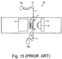
- Fig. 15 is a schematic view of an in-mold forming apparatus 10 for manufacturing such an in-mold formed article.
- the in-mold forming apparatus 10 is provided with a cavity-side block 11 fixed to the in-mold forming apparatus 10, a core-side block 12 arranged opposite to the cavity-side block 11 for moving in the left and right directions in the drawing, and a foil feeder 13 for feeding in-mold foil H.
- the cavity-side block 11 is provided with a cavity-side mold 11a
- the core-side block 12 is provided with a core-side mold 11b.
- the foil feeder 13 is provided with a foil sender 13a for feeding the in-mold foil H and a foil winding machine 13b for winding a base film B which is made by separating a pattern from the in-mold foil H.
- the in-mold foil H is positioned in the neighborhood of the cavity-side mold 11a, and the interval between the in-mold foil H and the cavity-side mold 11a when both the molds 11a and 11b are opened is about 2 to 3 mm.
- the in-mold foil H is composed of an adherent layer and a deposited layer which are laminated on the base film B via a separation layer, and a pattern layer is formed inside the adherent layer.
- the in-mold foil H is pinched by the cavity-side mold 11a and the core-side mold 11b, and after both the molds 11a and 11b are closed, resin is injected into a cavity formed by the cavity-side mold 11a and the core-side mold 11b.
- the separation layer is separated from the base film B, and the separation layer side is formed integrally with a formed article.
- Patent Document 1 Japanese Patent Disclosure (Kokai) Hei 7-329112
- Patent Document 2 Japanese Patent Disclosure (Kokai) 2000-108158
- the in-mold forming method aforementioned causes the following problem. Namely, after the forming is made, fine foil dusts P with a length of several microns to several mm may be separated and fallen from the in-mold foil H. When the foil dust P is adhered to a formed article or the cavity-side mold 11a and core-side mold 11b, at the next forming time, the foil dust P is transferred to the formed article as a dent. Further, when the dent is not found and the foil dust P is not wiped out, there is a fear of continuous manufacture of defective articles.
- the parts are transparent, so that the failure rate due to the dent is high, and the yield rate of some part is low such as 50% to 60%, and thereby an increase in the manufacturing cost is caused.
- One object of the present invention is to provide an in-mold forming apparatus, an in-mold forming method, and an in-mold formed article manufacturing method for preventing an occurrence of defective articles, and efficiently transferring a high resolution pattern and design to the outer surface of each formed article at the time of the in-mold forming. Further, another object of the present invention is to provide a dust collector for efficiently collecting fine dust.
- One aspect of the invention is to provide an in-mold forming apparatus including a first mold and a second mold for injection molding and a film feeding mechanism for feeding in-mold foil between the first mold and the second mold.
- a transfer foil is formed on the in-mold foil.
- the in-mold forming apparatus further includes a mold closing mechanism for closing the first mold and the second mold, thereby to fix the in-mold foil inside a cavity formed between the first mold and the second mold, a resin injection forming mechanism for injecting fused resin into the cavity, thereby to unit the transfer foil formed on the in-mold foil with the resin, and a charger arranged in the neighborhood of at least one of the first mold, the second mold, and the in-mold foil.
- the charger includes a charging unit for freeing ions and charging particles in the neighborhood of the in-mold foil, and an electrode for adsorbing the particles charged by the ions.
- One aspect of the invention is to provide an in-mold forming method including feeding in-mold foil between a first mold and a second mold for injection molding.
- a transfer foil is formed on the in-mold foil.
- the in-mold forming method further includes closing the first mold and the second mold, thereby to fix the in-mold foil inside a cavity formed between the first mold and the second mold, injecting fused resin into the cavity, thereby to unit the transfer foil formed on the in-mold foil with the resin, and freeing ions and charging particles in the neighborhood of the in-mold foil and adsorbing the particles charged by the ions.
- One aspect of the invention is to provide an in-mold formed article manufacturing method including feeding in-mold foil between a first mold and a second mold for injection molding.
- the transfer foil is formed on the in-mold foil.
- the in-mold formed article manufacturing method further includes closing the first mold and the second mold, thereby to fix the in-mold foil inside a cavity formed between the first mold and the second mold, injecting fused resin into the cavity, thereby to form an in-mold formed article and to unit the transfer foil formed on the in-mold foil with the in-mold formed article, and freeing ions and charging particles in the neighborhood of the in-mold foil and adsorbing the particles charged by the ions.
- One aspect of the invention is to provide a dust collector including a charging unit for freeing ions and charging particles, and an electrode for adsorbing the particles charged by the ions.
- an occurrence of defective articles is prevented and a high resolution pattern or design can be efficiently transferred to the outer surface of each formed article. Further, fine dust can be collected efficiently.
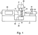
- Fig. 1 is a front view showing an in-mold forming apparatus 20 according to a first embodiment of the present invention
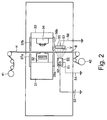
- Fig. 2 is a schematic view showing an essential part of the in-mold forming apparatus 20
- Fig. 3 is a front view showing an in-mold foil H used in the in-mold forming apparatus 20
- Figs. 4 and 5 are cross sectional views of the in-mold foil H cut off along a line X-X shown in Fig. 3 viewed in a direction of an arrow, respectively
- Fig. 6 is an illustration for showing an operation principle of the in-mold forming apparatus 20
- Figs. 7 to 9 are cross sectional views showing an injection forming step by the in-mold forming apparatus 20, respectively.
- numeral H indicates the in-mold foil
- B the base film
- P the foil dust.
- the in-mold forming apparatus 20 is provided with a frame 21 loaded on the floor, an injection forming mechanism 30 installed on the frame 21, an in-mold foil feeding mechanism 40 for feeding in-mold foil H, and a charger 50 for charging the in-mold foil H.
- the injection forming mechanism 30 is provided with a cavity-side block 31 fixed to the frame 21, a cavity-side mold (first mold) 32 installed on the cavity-side block 31, a core-side block 33 arranged opposite to the cavity-side block 31 for moving in the left and right directions in the drawing, a core-side mold (second mold) 34 installed on the core-side block 33 which can be combined with the cavity-side mold 32, an injection molder 35 for injecting fused resin into a cavity formed between the cavity-side mold 32 and the core-side mold 34, and a resin feeder 36 for feeding resin to the injection molder 35.
- the core-side block 33 has a function for moving toward the cavity-side block 31 thereby to close the cavity-side mold 32 and core-side mold 34.
- the circumference of the cavity-side mold 32 and the core-side mold 34 is openably shielded by a pair of upper shielding plates 37a and 37b and a pair of lower shielding plates 38a and 38b. Further, the pair of upper shielding plates 37a and 37b and the pair of lower shielding plates 38a and 38b are arranged not so as to make contact with the cavity-side block 31 and core-side block 33 when opening or closing the cavity-side mold 32 and the core-side mold 34.
- the in-mold foil feeding mechanism 40 is provided with a foil sender 41 for feeding the in-mold foil H and a foil winding machine 42 for winding the base film B which is made by separating the transfer foil F from the in-mold foil H.
- the in-mold foil H is positioned in the neighborhood of the cavity-side mold 32 and the interval between the in-mold foil H and the cavity-side mold 32 when both the molds 32 and 34 are opened is about 2 to 3 mm.
- the charger 50 is provided with a bottomed cylindrical charger body 51, a tungsten wire 52 arranged inside the charger body 51, a high-voltage DC power source 53 connected to one end of the tungsten wire 52, a ground wire 54 connected to the other end of the tungsten wire 52, a plate electrode 55 arranged opposite to the charger body 51 across the in-mold foil H, a ground wire 56 connected to the plate electrode 55, and a thin plate insulator 57 arranged in the neighborhood of the plate electrode 55 on the side of the charger body 51.
- the insulator 57 is made of resin or paper.
- the in-mold foil H has a thickness of about 40 ⁇ m to 50 ⁇ m, and is provided with the base film B made of PET resin and the transfer foils F arranged at fixed intervals in the winding direction of the base film B.
- a length detection mark Ba and width detection marks Bb for detecting the position of the in-mold foil H are formed and structured so as to put a pattern part E, which will be described later, in a predetermined position of the cavity-side mold 32.
- a separation layer K for simplifying separation after forming and an adherent layer S to be adhered to a formed article are laminated from the side of the base film B, and the pattern layer E is formed inside the adherent layer S.
- transfer foil F in which the separation layer K, a deposited primer layer J, and the adherent layer S are laminated from the side of the base film B, the pattern layer E is formed inside the deposited primer layer J, and a deposited layer T is formed inside the adherent layer S can be used.
- an in-mold formed article R for example, an external frame of a portable telephone is formed as indicated below.
- the in-mold foil H is sent by the foil sender 41, and on the basis of the length detection mark Ba and width detection mark Bb, and the in-mold foil H is positioned and fixed at a predetermined position of the cavity-side mold 32.
- the cavity-side mold 32 and core-side mold 34 are closed and fused resin Q is injected by the injection molder 35.
- the cavity-side mold 32 and the core-side mold 34 are opened, and the cooled and hardened in-mold formed article R to which the transfer foil F has been transferred is taken out.
- fine foil dusts P with a length of several microns to several mm are separated and fallen from the transfer foil F and are scattered around the cavity-side mold 32 and core-side mold 34.
- a high voltage of -11 kV is applied to the tungsten wire 52.
- the effect of collecting the foil dusts P is surely obtained with the charging by a high voltage of -11kV or less or +11kV or more (that is the absolute value of the high voltage is 11kV or more). But in some cases, the effect may be obtained with the charging by a high voltage the absolute value of which is 11kV or less.
- Negative ions M freed around the tungsten wire 52 by the glow discharge V charge negatively the in-mold foil H and its circumference. At this time, the foil dusts P scattered around are also charged negatively.
- the insulator 57 is formed, so that the foil dusts P charged negatively move toward a rear face 55b charged positively by the potential difference of the plate electrode 55, and are collected and adsorbed. Further, since the insulator 57 is installed, it is prevented that the in-mold foil H is charged and adsorbed by the surface 55a of the plate electrode 55, and thus the winding of the base film B is stopped.
- the foil dusts P are collected by the charger 50, so that an occurrence of defective articles due to the adhesion of the foil dusts P to the cavity-side mold 32 and core-side mold 34 can be minimized. Therefore, the in-mold formed articles R can be manufactured at a high yield rate. Therefore, portable telephones, mobile information terminal devices, and note-type personal computers can be manufactured in good quality at a low cost.
- the resin-made frame of a portable telephone is explained by referring to the in-mold forming example.
- the present invention can be applied to any parts of note-type personal computers, portable telephones, mobile information terminal devices, household electric appliances, and car parts and so on.
- Fig. 10 is a perspective view schematically showing an in-mold forming apparatus 60 according to a second embodiment of the present invention.
- Fig. 10 to the same functional parts as those shown in Fig. 2, the same numerals are assigned, and the detailed explanation thereof will be omitted.
- the charger 50 is installed only on the side of the foil winding machine 42 viewed from the cavity-side mold 32 and core-side mold 34.
- the chargers 50 are additionally installed on the side of the foil sender 41 and on the cavity-side mold 32 and core-side mold 34.
- the charger body 51 and the plate electrode 55 are installed in the symmetrical positions with respect to the in-mold foil H.
- Fig. 11 is a perspective view schematically showing an in-mold forming apparatus 70 according to a third embodiment of the present invention.
- Fig. 11 to the same functional parts as those shown in Figs. 2 and 10, the same numerals are assigned and the detailed explanation thereof will be omitted.
- the in-mold foil feeding mechanism 40 is installed only in the vertical direction.
- the in-mold foil feeding mechanisms 40 are arranged in the vertical and horizontal directions one by one. Therefore, in the in-mold forming apparatus 70, composite in-mold forming in which the in-mold foils H are arranged in the vertical direction and horizontal direction can be executed.
- the chargers 50 are installed in the positions corresponding to the cavity-side mold 32 and core-side mold 34 in each of the in-mold foil feeding mechanisms 40 respectively on the sides of the foil sender 41 and the foil winding machine 42, that is, four chargers 50 in total are arranged. Further, the charger bodies 51 and the plate electrodes 55 are installed in the symmetrical positions with respect to the in-mold foils H, respectively.
- Fig. 12 is a perspective view schematically showing an in-mold forming apparatus 80 according to a fourth embodiment of the present invention.
- Fig. 12 to the same functional parts as those shown in Fig. 2, the same numerals are assigned and the detailed explanation thereof will be omitted.
- the foil sender 41 is surrounded by a dustproof cover 81.
- the foil dusts P entering into the dustproof cover 81 can be removed.
- Fig. 13 is a perspective view showing a dust collector 200 according to a fifth embodiment of the present invention
- Fig. 14 is an illustration showing an operation principle of the dust collector 200.
- the dust collector 200 is provided with an arm 201 and a shoulder belt 202. At the front end of the arm 201, a discharge dust collector unit 210 is installed, and at the base end thereof, a power unit 220 is installed.
- a charger guide 211 and a bottomed cylindrical charger body 212 held by the charger guide 211 are installed. Inside the charger body 212, a charging electrode 213 is installed. At the opposite position of the charger body 212, a metallic electrode 215 held by an electrode guide 214 is installed.
- the power unit 220 is provided with a frame 221, a high-voltage power source 222 of 11 kV stored in the frame 221 having a negative electrode connected to the charging electrode 213 and a positive electrode connected to the metallic electrode 215, a DC power source 223 of 24 V, and a grounded 100-V plug 224 connected to the DC power source 223.
- the metallic electrode 215 is ensured with grounding by the grounded 100-V plug 224.
- Numeral 225 shown in Fig. 14 indicates a ground wire.
- the effect of collecting the dusts is surely obtained with the charging by a high voltage of -11kV or less or +11kV or more (that is the absolute value of the high voltage is 11kv or more). But in some cases, the effect may be obtained with the charging by a high voltage the absolute value of which is 11kV or less.
- the dust collector 200 structured like this, negative ions M freed from the charger body 212 charge negatively the surfaces of the objects and particles P in the air, and thus the particles P are collected by the metallic electrode 215 due to the potential difference. Further, the dust collector 200 can be moved, so that it charges various kinds of dust and collects the dusts by the metallic electrode 214 at an optional place while moving like a vacuum cleaner.
- the dust collector 200 according to the fifth embodiment various kinds of particles can be collected easily and surely.
- any embodiments having the same operation as in these embodiments aforementioned belong to the present invention, even if the forming methods and the materials, structures, voltages, currents, distances, and dimensions of the chargers are different. Further, in these embodiments, the negative DC charging is described, though the same effect may be obtained with the positive charging or the AC charging.
Landscapes
- Engineering & Computer Science (AREA)
- Manufacturing & Machinery (AREA)
- Mechanical Engineering (AREA)
- Injection Moulding Of Plastics Or The Like (AREA)
- Moulds For Moulding Plastics Or The Like (AREA)
- Electrostatic Separation (AREA)
Abstract
Description
- This application is based upon and claims the benefit of priority from the prior Japanese Patent Application No. 2004-306161, filed on October 20, 2004; the entire contents of which are incorporated herein by reference.
- The present invention relates to an in-mold forming apparatus, an in-mold forming method and an in-mold formed article manufacturing method, and more particularly relates to an in-mold forming apparatus, an in-mold forming method and an in-mold formed article manufacturing method for forming resin parts used for portable telephones, mobile information terminal devices, note-type personal computers, household electric appliances, car parts, and so on. Also, the present invention relates to a dust collector, and more particularly to a dust collector for efficiently collecting dust.
- Conventionally, resin is injection molded and simultaneously a pattern or characters are transferred to the surface of a formed article using in-mold foil, and thus an in-mold formed article is manufactured (for example, refer to Patent Documents 1 and 2). In-mold formed articles are widely used for portable telephones, note-type personal computers, mobile information terminal devices, household electric appliances, and car parts. Each in-mold formed article has an advantage that a high resolution image or design is transferred onto the outer surface thereof, thereby top coating is formed, and thus a firm transfer image can be formed.
- Fig. 15 is a schematic view of an in-
mold forming apparatus 10 for manufacturing such an in-mold formed article. The in-mold forming apparatus 10 is provided with a cavity-side block 11 fixed to the in-mold forming apparatus 10, a core-side block 12 arranged opposite to the cavity-side block 11 for moving in the left and right directions in the drawing, and afoil feeder 13 for feeding in-mold foil H. The cavity-side block 11 is provided with a cavity-side mold 11a, and the core-side block 12 is provided with a core-side mold 11b. - The
foil feeder 13 is provided with afoil sender 13a for feeding the in-mold foil H and afoil winding machine 13b for winding a base film B which is made by separating a pattern from the in-mold foil H. The in-mold foil H is positioned in the neighborhood of the cavity-side mold 11a, and the interval between the in-mold foil H and the cavity-side mold 11a when both themolds - The in-mold foil H is composed of an adherent layer and a deposited layer which are laminated on the base film B via a separation layer, and a pattern layer is formed inside the adherent layer.
- In the in-
mold forming apparatus 10 formed like this, the in-mold foil H is pinched by the cavity-side mold 11a and the core-side mold 11b, and after both themolds side mold 11a and the core-side mold 11b. As a result, in the in-mold foil H, the separation layer is separated from the base film B, and the separation layer side is formed integrally with a formed article.
Patent Document 1: Japanese Patent Disclosure (Kokai) Hei 7-329112
Patent Document 2: Japanese Patent Disclosure (Kokai) 2000-108158 - The in-mold forming method aforementioned causes the following problem. Namely, after the forming is made, fine foil dusts P with a length of several microns to several mm may be separated and fallen from the in-mold foil H. When the foil dust P is adhered to a formed article or the cavity-
side mold 11a and core-side mold 11b, at the next forming time, the foil dust P is transferred to the formed article as a dent. Further, when the dent is not found and the foil dust P is not wiped out, there is a fear of continuous manufacture of defective articles. - Particularly, in the display unit of the subliquid crystal panel of a portable telephone and so on, the parts are transparent, so that the failure rate due to the dent is high, and the yield rate of some part is low such as 50% to 60%, and thereby an increase in the manufacturing cost is caused.
- On the other hand, an apparatus having a simple constitution for collecting fine dust with a length of several microns to several mm fallen on the floor is desired.
- One object of the present invention is to provide an in-mold forming apparatus, an in-mold forming method, and an in-mold formed article manufacturing method for preventing an occurrence of defective articles, and efficiently transferring a high resolution pattern and design to the outer surface of each formed article at the time of the in-mold forming.
Further, another object of the present invention is to provide a dust collector for efficiently collecting fine dust. - One aspect of the invention is to provide an in-mold forming apparatus including a first mold and a second mold for injection molding and a film feeding mechanism for feeding in-mold foil between the first mold and the second mold. A transfer foil is formed on the in-mold foil. The in-mold forming apparatus further includes a mold closing mechanism for closing the first mold and the second mold, thereby to fix the in-mold foil inside a cavity formed between the first mold and the second mold, a resin injection forming mechanism for injecting fused resin into the cavity, thereby to unit the transfer foil formed on the in-mold foil with the resin, and a charger arranged in the neighborhood of at least one of the first mold, the second mold, and the in-mold foil. The charger includes a charging unit for freeing ions and charging particles in the neighborhood of the in-mold foil, and an electrode for adsorbing the particles charged by the ions.
- One aspect of the invention is to provide an in-mold forming method including feeding in-mold foil between a first mold and a second mold for injection molding. A transfer foil is formed on the in-mold foil. The in-mold forming method further includes closing the first mold and the second mold, thereby to fix the in-mold foil inside a cavity formed between the first mold and the second mold, injecting fused resin into the cavity, thereby to unit the transfer foil formed on the in-mold foil with the resin, and freeing ions and charging particles in the neighborhood of the in-mold foil and adsorbing the particles charged by the ions.
- One aspect of the invention is to provide an in-mold formed article manufacturing method including feeding in-mold foil between a first mold and a second mold for injection molding. The transfer foil is formed on the in-mold foil. The in-mold formed article manufacturing method further includes closing the first mold and the second mold, thereby to fix the in-mold foil inside a cavity formed between the first mold and the second mold, injecting fused resin into the cavity, thereby to form an in-mold formed article and to unit the transfer foil formed on the in-mold foil with the in-mold formed article, and freeing ions and charging particles in the neighborhood of the in-mold foil and adsorbing the particles charged by the ions.
- One aspect of the invention is to provide a dust collector including a charging unit for freeing ions and charging particles, and an electrode for adsorbing the particles charged by the ions.
- According to the present invention, an occurrence of defective articles is prevented and a high resolution pattern or design can be efficiently transferred to the outer surface of each formed article. Further, fine dust can be collected efficiently.
- A more complete appreciation of the invention and many of the attendant advantages thereof will be readily obtained as the same becomes better understood by reference to the following detailed description when considered in connection with the accompanying drawings, wherein:
- Fig. 1 is a front view showing an in-mold forming apparatus according to a first embodiment of the present invention;
- Fig. 2 is a schematic view showing an essential part of the in-mold forming apparatus shown in Fig. 1;
- Fig. 3 is a front view showing an in-mold foil used in the in-mold forming apparatus shown in Fig. 1;
- Fig. 4 is a cross sectional view showing an example of the in-mold foil cut off along a line X-X shown in Fig. 3 viewed in the direction of an arrow;
- Fig. 5 is a cross sectional view showing another example of the in-mold foil cut off along the line X-X shown in Fig. 3 viewed in the direction of the arrow;
- Fig. 6 is an illustration for showing an operation principle of the in-mold forming apparatus shown in Fig. 1;
- Fig. 7 is a cross sectional view showing an injection forming step by the in-mold forming apparatus shown in Fig. 1;
- Fig. 8 is a cross sectional view showing an injection forming step by the in-mold forming apparatus shown in Fig. 1;
- Fig. 9 is a cross sectional view showing an injection forming step by the in-mold forming apparatus shown in Fig. 1;
- Fig. 10 is a perspective view showing an in-mold forming apparatus according to a second embodiment of the present invention;
- Fig. 11 is a perspective view showing an in-mold forming apparatus according to a third embodiment of the present invention;
- Fig. 12 is a schematic view showing an in-mold forming apparatus according to a fourth embodiment of the present invention;
- Fig. 13 is a perspective view showing a dust collector according to a fifth embodiment of the present invention;
- Fig. 14 is an illustration showing an operation principle of the dust collector shown in Fig. 13; and
- Fig. 15 is a schematic view showing an example of a general in-mold forming apparatus.
- Referring now to the drawings, wherein like reference numerals designate identical or corresponding parts throughout the several views, the embodiments of this invention will be described below.
- Fig. 1 is a front view showing an in-
mold forming apparatus 20 according to a first embodiment of the present invention, Fig. 2 is a schematic view showing an essential part of the in-mold forming apparatus 20, and Fig. 3 is a front view showing an in-mold foil H used in the in-mold forming apparatus 20. Figs. 4 and 5 are cross sectional views of the in-mold foil H cut off along a line X-X shown in Fig. 3 viewed in a direction of an arrow, respectively, and Fig. 6 is an illustration for showing an operation principle of the in-mold forming apparatus 20. Figs. 7 to 9 are cross sectional views showing an injection forming step by the in-mold forming apparatus 20, respectively. Further, in these drawings, numeral H indicates the in-mold foil, B the base film, F a transfer foil, and P the foil dust. - As shown in Fig. 1, the in-
mold forming apparatus 20 is provided with aframe 21 loaded on the floor, aninjection forming mechanism 30 installed on theframe 21, an in-moldfoil feeding mechanism 40 for feeding in-mold foil H, and acharger 50 for charging the in-mold foil H. - The
injection forming mechanism 30 is provided with a cavity-side block 31 fixed to theframe 21, a cavity-side mold (first mold) 32 installed on the cavity-side block 31, a core-side block 33 arranged opposite to the cavity-side block 31 for moving in the left and right directions in the drawing, a core-side mold (second mold) 34 installed on the core-side block 33 which can be combined with the cavity-side mold 32, aninjection molder 35 for injecting fused resin into a cavity formed between the cavity-side mold 32 and the core-side mold 34, and aresin feeder 36 for feeding resin to theinjection molder 35. The core-side block 33 has a function for moving toward the cavity-side block 31 thereby to close the cavity-side mold 32 and core-side mold 34. - As shown in Fig. 2, the circumference of the cavity-
side mold 32 and the core-side mold 34 is openably shielded by a pair ofupper shielding plates lower shielding plates upper shielding plates lower shielding plates side block 31 and core-side block 33 when opening or closing the cavity-side mold 32 and the core-side mold 34. - As shown in Fig. 1, the in-mold
foil feeding mechanism 40 is provided with afoil sender 41 for feeding the in-mold foil H and afoil winding machine 42 for winding the base film B which is made by separating the transfer foil F from the in-mold foil H. The in-mold foil H is positioned in the neighborhood of the cavity-side mold 32 and the interval between the in-mold foil H and the cavity-side mold 32 when both themolds - As shown in Fig. 2, the
charger 50 is provided with a bottomedcylindrical charger body 51, atungsten wire 52 arranged inside thecharger body 51, a high-voltageDC power source 53 connected to one end of thetungsten wire 52, aground wire 54 connected to the other end of thetungsten wire 52, aplate electrode 55 arranged opposite to thecharger body 51 across the in-mold foil H, aground wire 56 connected to theplate electrode 55, and athin plate insulator 57 arranged in the neighborhood of theplate electrode 55 on the side of thecharger body 51. Theinsulator 57 is made of resin or paper. - As shown in Fig. 3, the in-mold foil H has a thickness of about 40 µm to 50 µm, and is provided with the base film B made of PET resin and the transfer foils F arranged at fixed intervals in the winding direction of the base film B. On the base film B, a length detection mark Ba and width detection marks Bb for detecting the position of the in-mold foil H are formed and structured so as to put a pattern part E, which will be described later, in a predetermined position of the cavity-
side mold 32. - As shown in Fig. 4, on the transfer foil F, a separation layer K for simplifying separation after forming and an adherent layer S to be adhered to a formed article are laminated from the side of the base film B, and the pattern layer E is formed inside the adherent layer S.
- Further, as shown in Fig. 5, transfer foil F in which the separation layer K, a deposited primer layer J, and the adherent layer S are laminated from the side of the base film B, the pattern layer E is formed inside the deposited primer layer J, and a deposited layer T is formed inside the adherent layer S can be used.
- In the in-
mold forming apparatus 20 structured like this, an in-mold formed article R, for example, an external frame of a portable telephone is formed as indicated below. - Firstly, as shown in Fig. 7, between the cavity-
side mold 32 and the core-side mold 34, the in-mold foil H is sent by thefoil sender 41, and on the basis of the length detection mark Ba and width detection mark Bb, and the in-mold foil H is positioned and fixed at a predetermined position of the cavity-side mold 32. - Next, as shown in Fig. 8, the cavity-
side mold 32 and core-side mold 34 are closed and fused resin Q is injected by theinjection molder 35. Next, as shown in Fig. 9, the cavity-side mold 32 and the core-side mold 34 are opened, and the cooled and hardened in-mold formed article R to which the transfer foil F has been transferred is taken out. At this time, fine foil dusts P with a length of several microns to several mm are separated and fallen from the transfer foil F and are scattered around the cavity-side mold 32 and core-side mold 34. - On the other hand, as shown in Figs. 2 and 6, in the
charger 50, a high voltage of -11 kV is applied to thetungsten wire 52. Here, the effect of collecting the foil dusts P is surely obtained with the charging by a high voltage of -11kV or less or +11kV or more (that is the absolute value of the high voltage is 11kV or more). But in some cases, the effect may be obtained with the charging by a high voltage the absolute value of which is 11kV or less. Negative ions M freed around thetungsten wire 52 by the glow discharge V charge negatively the in-mold foil H and its circumference. At this time, the foil dusts P scattered around are also charged negatively. Further, on the side of asurface 55a of theplate electrode 55, theinsulator 57 is formed, so that the foil dusts P charged negatively move toward arear face 55b charged positively by the potential difference of theplate electrode 55, and are collected and adsorbed. Further, since theinsulator 57 is installed, it is prevented that the in-mold foil H is charged and adsorbed by thesurface 55a of theplate electrode 55, and thus the winding of the base film B is stopped. - According to the in-
mold forming apparatus 20 according to the first embodiment, the foil dusts P are collected by thecharger 50, so that an occurrence of defective articles due to the adhesion of the foil dusts P to the cavity-side mold 32 and core-side mold 34 can be minimized. Therefore, the in-mold formed articles R can be manufactured at a high yield rate. Therefore, portable telephones, mobile information terminal devices, and note-type personal computers can be manufactured in good quality at a low cost. - In the embodiment aforementioned, the resin-made frame of a portable telephone is explained by referring to the in-mold forming example. However, the present invention can be applied to any parts of note-type personal computers, portable telephones, mobile information terminal devices, household electric appliances, and car parts and so on.
- Fig. 10 is a perspective view schematically showing an in-
mold forming apparatus 60 according to a second embodiment of the present invention. In Fig. 10, to the same functional parts as those shown in Fig. 2, the same numerals are assigned, and the detailed explanation thereof will be omitted. - In the in-
mold forming apparatus 20 according to the first embodiment aforementioned, thecharger 50 is installed only on the side of thefoil winding machine 42 viewed from the cavity-side mold 32 and core-side mold 34. However, in the in-mold forming apparatus 60 according to this embodiment, thechargers 50 are additionally installed on the side of thefoil sender 41 and on the cavity-side mold 32 and core-side mold 34. Further, thecharger body 51 and theplate electrode 55 are installed in the symmetrical positions with respect to the in-mold foil H. - Also in the in-
mold forming apparatus 60 structured like this, the same effects as those of the in-mold forming apparatus 20 aforementioned can be obtained. - Fig. 11 is a perspective view schematically showing an in-
mold forming apparatus 70 according to a third embodiment of the present invention. In Fig. 11, to the same functional parts as those shown in Figs. 2 and 10, the same numerals are assigned and the detailed explanation thereof will be omitted. - In the in-
mold forming apparatus 20 according to the first embodiment aforementioned and the in-mold forming apparatus 60 according to the second embodiment aforementioned, the in-moldfoil feeding mechanism 40 is installed only in the vertical direction. However, in the in-mold forming apparatus 70 according to this embodiment, the in-moldfoil feeding mechanisms 40 are arranged in the vertical and horizontal directions one by one. Therefore, in the in-mold forming apparatus 70, composite in-mold forming in which the in-mold foils H are arranged in the vertical direction and horizontal direction can be executed. - Further, the
chargers 50 are installed in the positions corresponding to the cavity-side mold 32 and core-side mold 34 in each of the in-moldfoil feeding mechanisms 40 respectively on the sides of thefoil sender 41 and thefoil winding machine 42, that is, fourchargers 50 in total are arranged. Further, thecharger bodies 51 and theplate electrodes 55 are installed in the symmetrical positions with respect to the in-mold foils H, respectively. - Also in the in-
mold forming apparatus 70 structured like this, the same effects as those of the in-mold forming apparatus 20 aforementioned can be obtained. - Fig. 12 is a perspective view schematically showing an in-
mold forming apparatus 80 according to a fourth embodiment of the present invention. In Fig. 12, to the same functional parts as those shown in Fig. 2, the same numerals are assigned and the detailed explanation thereof will be omitted. - As shown in Fig. 12, in this embodiment, the
foil sender 41 is surrounded by adustproof cover 81. When air is exhausted from the inside of thedustproof cover 81, the foil dusts P entering into thedustproof cover 81 can be removed. - Also in the in-
mold forming apparatus 80 structured like this, the same effects as those of the in-mold forming apparatus 20 aforementioned can be obtained. - Fig. 13 is a perspective view showing a
dust collector 200 according to a fifth embodiment of the present invention, and Fig. 14 is an illustration showing an operation principle of thedust collector 200. - The
dust collector 200 is provided with anarm 201 and ashoulder belt 202. At the front end of thearm 201, a dischargedust collector unit 210 is installed, and at the base end thereof, apower unit 220 is installed. - On the discharge
dust collector unit 210, as shown in Fig. 14, acharger guide 211 and a bottomedcylindrical charger body 212 held by thecharger guide 211 are installed. Inside thecharger body 212, a chargingelectrode 213 is installed. At the opposite position of thecharger body 212, ametallic electrode 215 held by anelectrode guide 214 is installed. - The
power unit 220 is provided with aframe 221, a high-voltage power source 222 of 11 kV stored in theframe 221 having a negative electrode connected to the chargingelectrode 213 and a positive electrode connected to themetallic electrode 215, aDC power source 223 of 24 V, and a grounded 100-V plug 224 connected to theDC power source 223. Themetallic electrode 215 is ensured with grounding by the grounded 100-V plug 224.Numeral 225 shown in Fig. 14 indicates a ground wire. Here, the effect of collecting the dusts is surely obtained with the charging by a high voltage of -11kV or less or +11kV or more (that is the absolute value of the high voltage is 11kv or more). But in some cases, the effect may be obtained with the charging by a high voltage the absolute value of which is 11kV or less. - According to the
dust collector 200 structured like this, negative ions M freed from thecharger body 212 charge negatively the surfaces of the objects and particles P in the air, and thus the particles P are collected by themetallic electrode 215 due to the potential difference. Further, thedust collector 200 can be moved, so that it charges various kinds of dust and collects the dusts by themetallic electrode 214 at an optional place while moving like a vacuum cleaner. - As described above, by the
dust collector 200 according to the fifth embodiment, various kinds of particles can be collected easily and surely. - In addition to the embodiments aforementioned, any embodiments having the same operation as in these embodiments aforementioned belong to the present invention, even if the forming methods and the materials, structures, voltages, currents, distances, and dimensions of the chargers are different. Further, in these embodiments, the negative DC charging is described, though the same effect may be obtained with the positive charging or the AC charging.
- Obviously, numerous modifications and variations of the present invention are possible in light of the above teachings. It is therefore to be understood that within the scope of the appended claims, the invention may be practiced otherwise than as specifically described herein.
Claims (10)
- An in-mold forming apparatus, comprising:a first mold and a second mold for injection molding;a film feeding mechanism for feeding in-mold foil between said first mold and said second mold;a transfer foil being formed on said in-mold foil;a mold closing mechanism for closing said first mold and said second mold, thereby to fix said in-mold foil inside a cavity formed between said first mold and said second mold;a resin injection forming mechanism for injecting fused resin into said cavity, thereby to unit said transfer foil formed on said in-mold foil with said resin; anda charger arranged in the neighborhood of at least one of said first mold, said second mold, and said in-mold foil;said charger including a charging unit for freeing ions and charging particles in the neighborhood of said in-mold foil, and an electrode for adsorbing said particles charged by said ions.
- The in-mold forming apparatus according to Claim 1, wherein:said charging unit includes a high-voltage DC power source and a glow discharger connected to said high-voltage DC power source.
- The in-mold forming apparatus according to Claim 1, wherein:said charging unit and said electrode are arranged opposite to each other across said in-mold foil.
- The in-mold forming apparatus according to Claim 3, wherein:said electrode includes an insulator arranged on said electrode opposite to said charging unit.
- The in-mold forming apparatus according to Claim 1, wherein said film feeding mechanism includes:a foil sender for feeding said in-mold foil; anda foil winding machine for winding a base film made by separating said transfer foil from said in-mold foil.
- The in-mold forming apparatus according to Claim 5, wherein:said charger includes a first charger and a second charger arranged in the neighborhood of said first mold and said second mold;said first charger is arranged on a side of said foil sender; andsaid second charger is arranged on a side of said foil winding machine.
- The in-mold forming apparatus according to Claim 5, wherein:said foil sender further includes a dustproof cover for surrounding said foil sender to remove a particle entering into said dustproof cover.
- An in-mold forming method, comprising:feeding in-mold foil between a first mold and a second mold for injection molding;transfer foil being formed on said in-mold foil;closing said first mold and said second mold, thereby to fix said in-mold foil inside a cavity formed between said first mold and said second mold;injecting fused resin into said cavity, thereby to unit said transfer foil formed on said in-mold foil with said resin; andfreeing ions and charging particles in the neighborhood of said in-mold foil and adsorbing said particles charged by said ions.
- An in-mold formed article manufacturing method, comprising:feeding in-mold foil between a first mold and a second mold for injection molding;transfer foil being formed on said in-mold foil;closing said first mold and said second mold, thereby to fix said in-mold foil inside a cavity formed between said first mold and said second mold;injecting fused resin into said cavity, thereby to form an in-mold formed article and to unit said transfer foil formed on said in-mold foil with said in-mold formed article; andfreeing ions and charging particles in the neighborhood of said in-mold foil and adsorbing said particles charged by said ions.
- A dust collector, comprising:a charging unit for freeing ions and charging particles; andan electrode for adsorbing said particles charged by said ions.
Priority Applications (1)
| Application Number | Priority Date | Filing Date | Title |
|---|---|---|---|
| EP08160965.3A EP1985432A3 (en) | 2004-10-20 | 2005-10-19 | A dust collector |
Applications Claiming Priority (1)
| Application Number | Priority Date | Filing Date | Title |
|---|---|---|---|
| JP2004306161 | 2004-10-20 |
Related Child Applications (1)
| Application Number | Title | Priority Date | Filing Date |
|---|---|---|---|
| EP08160965.3A Division EP1985432A3 (en) | 2004-10-20 | 2005-10-19 | A dust collector |
Publications (1)
| Publication Number | Publication Date |
|---|---|
| EP1650000A1 true EP1650000A1 (en) | 2006-04-26 |
Family
ID=35658906
Family Applications (2)
| Application Number | Title | Priority Date | Filing Date |
|---|---|---|---|
| EP08160965.3A Withdrawn EP1985432A3 (en) | 2004-10-20 | 2005-10-19 | A dust collector |
| EP05022784A Withdrawn EP1650000A1 (en) | 2004-10-20 | 2005-10-19 | Apparatus and method for in-mold forming, and dust collector |
Family Applications Before (1)
| Application Number | Title | Priority Date | Filing Date |
|---|---|---|---|
| EP08160965.3A Withdrawn EP1985432A3 (en) | 2004-10-20 | 2005-10-19 | A dust collector |
Country Status (3)
| Country | Link |
|---|---|
| US (1) | US8235696B2 (en) |
| EP (2) | EP1985432A3 (en) |
| CN (1) | CN100553930C (en) |
Families Citing this family (6)
| Publication number | Priority date | Publication date | Assignee | Title |
|---|---|---|---|---|
| DE102006041415B4 (en) * | 2005-10-13 | 2021-07-08 | Engel Austria Gmbh | Device for molding plastic parts onto a workpiece |
| CN101280855B (en) * | 2007-04-06 | 2011-02-02 | 康准电子科技(昆山)有限公司 | Switch device |
| JP5818962B2 (en) | 2011-03-23 | 2015-11-18 | エスアールアイ インターナショナルSRI International | Active electroadhesive cleaning |
| US9358590B2 (en) | 2011-03-23 | 2016-06-07 | Sri International | Electroadhesive surface cleaner |
| CN108237660A (en) * | 2018-01-09 | 2018-07-03 | 国安瑞(北京)科技有限公司 | The manufacturing device and method of heat exchange monomer |
| CN109454809B (en) * | 2018-12-27 | 2020-12-22 | 东莞华誉精密技术有限公司 | IMT intramode pad printing device and method |
Citations (5)
| Publication number | Priority date | Publication date | Assignee | Title |
|---|---|---|---|---|
| US5000903A (en) * | 1989-04-06 | 1991-03-19 | Libbey-Owens-Ford Co. | Method of molding plastic products having chemically bonded protective coatings |
| JPH07329112A (en) * | 1994-06-13 | 1995-12-19 | Nissha Printing Co Ltd | Transfer foil for laser marking and manufacture of molded article with decorating pattern, utilizing transfer foil |
| EP0840357A2 (en) * | 1996-11-05 | 1998-05-06 | Ebara Corporation | Method and apparatus for removing particles from surface of article |
| JP2000108158A (en) * | 1998-10-05 | 2000-04-18 | Nissha Printing Co Ltd | Manufacture of in-mold molding |
| US6156411A (en) * | 1998-02-06 | 2000-12-05 | General Motors Corporation | Decorative backlit components using transparent thermoplastic elastomers and methods of making the same |
Family Cites Families (2)
| Publication number | Priority date | Publication date | Assignee | Title |
|---|---|---|---|---|
| EP1431828A1 (en) * | 2002-12-20 | 2004-06-23 | ASML Netherlands B.V. | Method for cleaning a surface of a component of a lithographic projection apparatus, lithographic projection apparatus, device manufacturing method and cleaning system |
| JP4022164B2 (en) | 2003-04-02 | 2007-12-12 | 日東精工株式会社 | Automatic screwing machine and screwing method |
-
2005
- 2005-10-18 US US11/251,826 patent/US8235696B2/en not_active Expired - Fee Related
- 2005-10-19 EP EP08160965.3A patent/EP1985432A3/en not_active Withdrawn
- 2005-10-19 EP EP05022784A patent/EP1650000A1/en not_active Withdrawn
- 2005-10-20 CN CNB2005101162019A patent/CN100553930C/en not_active Expired - Fee Related
Patent Citations (5)
| Publication number | Priority date | Publication date | Assignee | Title |
|---|---|---|---|---|
| US5000903A (en) * | 1989-04-06 | 1991-03-19 | Libbey-Owens-Ford Co. | Method of molding plastic products having chemically bonded protective coatings |
| JPH07329112A (en) * | 1994-06-13 | 1995-12-19 | Nissha Printing Co Ltd | Transfer foil for laser marking and manufacture of molded article with decorating pattern, utilizing transfer foil |
| EP0840357A2 (en) * | 1996-11-05 | 1998-05-06 | Ebara Corporation | Method and apparatus for removing particles from surface of article |
| US6156411A (en) * | 1998-02-06 | 2000-12-05 | General Motors Corporation | Decorative backlit components using transparent thermoplastic elastomers and methods of making the same |
| JP2000108158A (en) * | 1998-10-05 | 2000-04-18 | Nissha Printing Co Ltd | Manufacture of in-mold molding |
Non-Patent Citations (2)
| Title |
|---|
| PATENT ABSTRACTS OF JAPAN vol. 1996, no. 04 30 April 1996 (1996-04-30) * |
| PATENT ABSTRACTS OF JAPAN vol. 2000, no. 07 29 September 2000 (2000-09-29) * |
Also Published As
| Publication number | Publication date |
|---|---|
| CN1762679A (en) | 2006-04-26 |
| US20060082019A1 (en) | 2006-04-20 |
| US8235696B2 (en) | 2012-08-07 |
| CN100553930C (en) | 2009-10-28 |
| EP1985432A3 (en) | 2014-06-04 |
| EP1985432A2 (en) | 2008-10-29 |
Similar Documents
| Publication | Publication Date | Title |
|---|---|---|
| US8235696B2 (en) | In-mold forming apparatus, in-mold forming method, in-mold formed article manufacturing method, and dust collector | |
| Yamamoto et al. | Improving withstand voltage by roughening the surface of an insulating spacer used in vacuum | |
| WO2013183914A1 (en) | Apparatus for charging and method for charging raw material | |
| US6315501B1 (en) | Air stream particulate collecting transfer apparatus | |
| CN1694296A (en) | Plastic molding type secondary battery and method of forming the same | |
| KR100856371B1 (en) | Electronic parts container | |
| JP4077478B2 (en) | In-mold molding apparatus, in-mold molding method, in-mold molded product manufacturing method, and dust collector | |
| JP7564727B2 (en) | Electrostatic film formation device and method for manufacturing all-solid-state secondary battery using the same | |
| CN204367547U (en) | The capacitance plate treadmill type printing machine of band ion blower | |
| WO2007136809A3 (en) | Electrostatic chuck to limit particle deposits thereon | |
| FI121936B (en) | transfer of powdery particles | |
| CN113086739B (en) | Stripping device and stripping method | |
| CN118055808A (en) | Electric dust collector and dust collecting method using the same | |
| CN219322482U (en) | Camera module and electronic equipment | |
| EP2702653B1 (en) | High-voltage electrode arrangement | |
| US4785372A (en) | Method and device for charging or discharging member | |
| JP2006240906A (en) | Optical element molding method, optical element manufacturing method, and optical element molding apparatus | |
| JPS60232570A (en) | discharger | |
| CN104429167A (en) | Eliminator | |
| JP2624222B2 (en) | IC package storage container, storage method and transport method thereof | |
| TWI248908B (en) | Electronic component container | |
| TW202607545A (en) | Electrostatic capacitance sensor | |
| CN114316824A (en) | Production device and production process for lipophilic strong-lithium tab glue | |
| EP3454574A1 (en) | A head-worn device having electrostatic discharge protection | |
| JP2001230097A (en) | Antistatic system for battery-powered equipment |
Legal Events
| Date | Code | Title | Description |
|---|---|---|---|
| PUAI | Public reference made under article 153(3) epc to a published international application that has entered the european phase |
Free format text: ORIGINAL CODE: 0009012 |
|
| 17P | Request for examination filed |
Effective date: 20051019 |
|
| AK | Designated contracting states |
Kind code of ref document: A1 Designated state(s): AT BE BG CH CY CZ DE DK EE ES FI FR GB GR HU IE IS IT LI LT LU LV MC NL PL PT RO SE SI SK TR |
|
| AX | Request for extension of the european patent |
Extension state: AL BA HR MK YU |
|
| 17Q | First examination report despatched |
Effective date: 20060802 |
|
| AKX | Designation fees paid |
Designated state(s): DE FR GB |
|
| GRAP | Despatch of communication of intention to grant a patent |
Free format text: ORIGINAL CODE: EPIDOSNIGR1 |
|
| RIC1 | Information provided on ipc code assigned before grant |
Ipc: B03C 3/017 20060101ALI20111010BHEP Ipc: B08B 6/00 20060101ALI20111010BHEP Ipc: B29C 45/17 20060101ALI20111010BHEP Ipc: B29C 45/14 20060101AFI20111010BHEP |
|
| RTI1 | Title (correction) |
Free format text: APPARATUS AND METHOD FOR IN-MOLD FORMING |
|
| STAA | Information on the status of an ep patent application or granted ep patent |
Free format text: STATUS: THE APPLICATION IS DEEMED TO BE WITHDRAWN |
|
| 18D | Application deemed to be withdrawn |
Effective date: 20120320 |