EP1649880B1 - Fluid management flow implants of improved occlusion resistance - Google Patents
Fluid management flow implants of improved occlusion resistance Download PDFInfo
- Publication number
- EP1649880B1 EP1649880B1 EP05256107A EP05256107A EP1649880B1 EP 1649880 B1 EP1649880 B1 EP 1649880B1 EP 05256107 A EP05256107 A EP 05256107A EP 05256107 A EP05256107 A EP 05256107A EP 1649880 B1 EP1649880 B1 EP 1649880B1
- Authority
- EP
- European Patent Office
- Prior art keywords
- catheter
- implant
- drug
- inhibitors
- agents
- Prior art date
- Legal status (The legal status is an assumption and is not a legal conclusion. Google has not performed a legal analysis and makes no representation as to the accuracy of the status listed.)
- Active
Links
- 239000012530 fluid Substances 0.000 title claims abstract description 35
- 239000007943 implant Substances 0.000 title claims description 24
- 229940079593 drug Drugs 0.000 claims description 51
- 239000003814 drug Substances 0.000 claims description 47
- 239000004599 antimicrobial Substances 0.000 claims description 33
- 238000009826 distribution Methods 0.000 claims description 13
- 230000002708 enhancing effect Effects 0.000 claims description 13
- 208000003906 hydrocephalus Diseases 0.000 claims description 12
- -1 heteroaryl acetic acids Chemical class 0.000 claims description 10
- 239000003795 chemical substances by application Substances 0.000 claims description 9
- ZAHRKKWIAAJSAO-UHFFFAOYSA-N rapamycin Natural products COCC(O)C(=C/C(C)C(=O)CC(OC(=O)C1CCCCN1C(=O)C(=O)C2(O)OC(CC(OC)C(=CC=CC=CC(C)CC(C)C(=O)C)C)CCC2C)C(C)CC3CCC(O)C(C3)OC)C ZAHRKKWIAAJSAO-UHFFFAOYSA-N 0.000 claims description 8
- 229960002930 sirolimus Drugs 0.000 claims description 8
- QFJCIRLUMZQUOT-HPLJOQBZSA-N sirolimus Chemical compound C1C[C@@H](O)[C@H](OC)C[C@@H]1C[C@@H](C)[C@H]1OC(=O)[C@@H]2CCCCN2C(=O)C(=O)[C@](O)(O2)[C@H](C)CC[C@H]2C[C@H](OC)/C(C)=C/C=C/C=C/[C@@H](C)C[C@@H](C)C(=O)[C@H](OC)[C@H](O)/C(C)=C/[C@@H](C)C(=O)C1 QFJCIRLUMZQUOT-HPLJOQBZSA-N 0.000 claims description 8
- 239000003112 inhibitor Substances 0.000 claims description 7
- ULGZDMOVFRHVEP-RWJQBGPGSA-N Erythromycin Chemical compound O([C@@H]1[C@@H](C)C(=O)O[C@@H]([C@@]([C@H](O)[C@@H](C)C(=O)[C@H](C)C[C@@](C)(O)[C@H](O[C@H]2[C@@H]([C@H](C[C@@H](C)O2)N(C)C)O)[C@H]1C)(C)O)CC)[C@H]1C[C@@](C)(OC)[C@@H](O)[C@H](C)O1 ULGZDMOVFRHVEP-RWJQBGPGSA-N 0.000 claims description 6
- MYSWGUAQZAJSOK-UHFFFAOYSA-N ciprofloxacin Chemical compound C12=CC(N3CCNCC3)=C(F)C=C2C(=O)C(C(=O)O)=CN1C1CC1 MYSWGUAQZAJSOK-UHFFFAOYSA-N 0.000 claims description 6
- 230000008467 tissue growth Effects 0.000 claims description 6
- 239000002253 acid Substances 0.000 claims description 5
- 150000007513 acids Chemical class 0.000 claims description 5
- 230000000845 anti-microbial effect Effects 0.000 claims description 5
- 230000001028 anti-proliverative effect Effects 0.000 claims description 5
- KDLRVYVGXIQJDK-AWPVFWJPSA-N clindamycin Chemical compound CN1C[C@H](CCC)C[C@H]1C(=O)N[C@H]([C@H](C)Cl)[C@@H]1[C@H](O)[C@H](O)[C@@H](O)[C@@H](SC)O1 KDLRVYVGXIQJDK-AWPVFWJPSA-N 0.000 claims description 5
- 229960001225 rifampicin Drugs 0.000 claims description 5
- JQXXHWHPUNPDRT-WLSIYKJHSA-N rifampicin Chemical compound O([C@](C1=O)(C)O/C=C/[C@@H]([C@H]([C@@H](OC(C)=O)[C@H](C)[C@H](O)[C@H](C)[C@@H](O)[C@@H](C)\C=C\C=C(C)/C(=O)NC=2C(O)=C3C([O-])=C4C)C)OC)C4=C1C3=C(O)C=2\C=N\N1CC[NH+](C)CC1 JQXXHWHPUNPDRT-WLSIYKJHSA-N 0.000 claims description 5
- MINDHVHHQZYEEK-UHFFFAOYSA-N (E)-(2S,3R,4R,5S)-5-[(2S,3S,4S,5S)-2,3-epoxy-5-hydroxy-4-methylhexyl]tetrahydro-3,4-dihydroxy-(beta)-methyl-2H-pyran-2-crotonic acid ester with 9-hydroxynonanoic acid Natural products CC(O)C(C)C1OC1CC1C(O)C(O)C(CC(C)=CC(=O)OCCCCCCCCC(O)=O)OC1 MINDHVHHQZYEEK-UHFFFAOYSA-N 0.000 claims description 4
- 108050007372 Fibroblast Growth Factor Proteins 0.000 claims description 4
- 102000018233 Fibroblast Growth Factor Human genes 0.000 claims description 4
- SIKJAQJRHWYJAI-UHFFFAOYSA-N Indole Chemical compound C1=CC=C2NC=CC2=C1 SIKJAQJRHWYJAI-UHFFFAOYSA-N 0.000 claims description 4
- 229930012538 Paclitaxel Natural products 0.000 claims description 4
- 108010073929 Vascular Endothelial Growth Factor A Proteins 0.000 claims description 4
- 102000005789 Vascular Endothelial Growth Factors Human genes 0.000 claims description 4
- 108010019530 Vascular Endothelial Growth Factors Proteins 0.000 claims description 4
- 230000002927 anti-mitotic effect Effects 0.000 claims description 4
- 229940126864 fibroblast growth factor Drugs 0.000 claims description 4
- 229960000282 metronidazole Drugs 0.000 claims description 4
- VAOCPAMSLUNLGC-UHFFFAOYSA-N metronidazole Chemical compound CC1=NC=C([N+]([O-])=O)N1CCO VAOCPAMSLUNLGC-UHFFFAOYSA-N 0.000 claims description 4
- CFCUWKMKBJTWLW-BKHRDMLASA-N mithramycin Chemical compound O([C@@H]1C[C@@H](O[C@H](C)[C@H]1O)OC=1C=C2C=C3C[C@H]([C@@H](C(=O)C3=C(O)C2=C(O)C=1C)O[C@@H]1O[C@H](C)[C@@H](O)[C@H](O[C@@H]2O[C@H](C)[C@H](O)[C@H](O[C@@H]3O[C@H](C)[C@@H](O)[C@@](C)(O)C3)C2)C1)[C@H](OC)C(=O)[C@@H](O)[C@@H](C)O)[C@H]1C[C@@H](O)[C@H](O)[C@@H](C)O1 CFCUWKMKBJTWLW-BKHRDMLASA-N 0.000 claims description 4
- 229960003128 mupirocin Drugs 0.000 claims description 4
- 229930187697 mupirocin Natural products 0.000 claims description 4
- DDHVILIIHBIMQU-YJGQQKNPSA-L mupirocin calcium hydrate Chemical compound O.O.[Ca+2].C[C@H](O)[C@H](C)[C@@H]1O[C@H]1C[C@@H]1[C@@H](O)[C@@H](O)[C@H](C\C(C)=C\C(=O)OCCCCCCCCC([O-])=O)OC1.C[C@H](O)[C@H](C)[C@@H]1O[C@H]1C[C@@H]1[C@@H](O)[C@@H](O)[C@H](C\C(C)=C\C(=O)OCCCCCCCCC([O-])=O)OC1 DDHVILIIHBIMQU-YJGQQKNPSA-L 0.000 claims description 4
- 229960001592 paclitaxel Drugs 0.000 claims description 4
- BASFCYQUMIYNBI-UHFFFAOYSA-N platinum Chemical compound [Pt] BASFCYQUMIYNBI-UHFFFAOYSA-N 0.000 claims description 4
- 229960003171 plicamycin Drugs 0.000 claims description 4
- RCINICONZNJXQF-MZXODVADSA-N taxol Chemical compound O([C@@H]1[C@@]2(C[C@@H](C(C)=C(C2(C)C)[C@H](C([C@]2(C)[C@@H](O)C[C@H]3OC[C@]3([C@H]21)OC(C)=O)=O)OC(=O)C)OC(=O)[C@H](O)[C@@H](NC(=O)C=1C=CC=CC=1)C=1C=CC=CC=1)O)C(=O)C1=CC=CC=C1 RCINICONZNJXQF-MZXODVADSA-N 0.000 claims description 4
- IEDVJHCEMCRBQM-UHFFFAOYSA-N trimethoprim Chemical compound COC1=C(OC)C(OC)=CC(CC=2C(=NC(N)=NC=2)N)=C1 IEDVJHCEMCRBQM-UHFFFAOYSA-N 0.000 claims description 4
- 229960001082 trimethoprim Drugs 0.000 claims description 4
- APKFDSVGJQXUKY-KKGHZKTASA-N Amphotericin-B Natural products O[C@H]1[C@@H](N)[C@H](O)[C@@H](C)O[C@H]1O[C@H]1C=CC=CC=CC=CC=CC=CC=C[C@H](C)[C@@H](O)[C@@H](C)[C@H](C)OC(=O)C[C@H](O)C[C@H](O)CC[C@@H](O)[C@H](O)C[C@H](O)C[C@](O)(C[C@H](O)[C@H]2C(O)=O)O[C@H]2C1 APKFDSVGJQXUKY-KKGHZKTASA-N 0.000 claims description 3
- WZPBZJONDBGPKJ-UHFFFAOYSA-N Antibiotic SQ 26917 Natural products O=C1N(S(O)(=O)=O)C(C)C1NC(=O)C(=NOC(C)(C)C(O)=O)C1=CSC(N)=N1 WZPBZJONDBGPKJ-UHFFFAOYSA-N 0.000 claims description 3
- CEAZRRDELHUEMR-URQXQFDESA-N Gentamicin Chemical compound O1[C@H](C(C)NC)CC[C@@H](N)[C@H]1O[C@H]1[C@H](O)[C@@H](O[C@@H]2[C@@H]([C@@H](NC)[C@@](C)(O)CO2)O)[C@H](N)C[C@@H]1N CEAZRRDELHUEMR-URQXQFDESA-N 0.000 claims description 3
- 229930182566 Gentamicin Natural products 0.000 claims description 3
- WKDDRNSBRWANNC-UHFFFAOYSA-N Thienamycin Natural products C1C(SCCN)=C(C(O)=O)N2C(=O)C(C(O)C)C21 WKDDRNSBRWANNC-UHFFFAOYSA-N 0.000 claims description 3
- 108010059993 Vancomycin Proteins 0.000 claims description 3
- APKFDSVGJQXUKY-INPOYWNPSA-N amphotericin B Chemical compound O[C@H]1[C@@H](N)[C@H](O)[C@@H](C)O[C@H]1O[C@H]1/C=C/C=C/C=C/C=C/C=C/C=C/C=C/[C@H](C)[C@@H](O)[C@@H](C)[C@H](C)OC(=O)C[C@H](O)C[C@H](O)CC[C@@H](O)[C@H](O)C[C@H](O)C[C@](O)(C[C@H](O)[C@H]2C(O)=O)O[C@H]2C1 APKFDSVGJQXUKY-INPOYWNPSA-N 0.000 claims description 3
- 229960003942 amphotericin b Drugs 0.000 claims description 3
- WZPBZJONDBGPKJ-VEHQQRBSSA-N aztreonam Chemical compound O=C1N(S([O-])(=O)=O)[C@@H](C)[C@@H]1NC(=O)C(=N/OC(C)(C)C(O)=O)\C1=CSC([NH3+])=N1 WZPBZJONDBGPKJ-VEHQQRBSSA-N 0.000 claims description 3
- 229960003644 aztreonam Drugs 0.000 claims description 3
- 229960001139 cefazolin Drugs 0.000 claims description 3
- MLYYVTUWGNIJIB-BXKDBHETSA-N cefazolin Chemical compound S1C(C)=NN=C1SCC1=C(C(O)=O)N2C(=O)[C@@H](NC(=O)CN3N=NN=C3)[C@H]2SC1 MLYYVTUWGNIJIB-BXKDBHETSA-N 0.000 claims description 3
- 229960003405 ciprofloxacin Drugs 0.000 claims description 3
- 229960002227 clindamycin Drugs 0.000 claims description 3
- 229960003276 erythromycin Drugs 0.000 claims description 3
- 229960004884 fluconazole Drugs 0.000 claims description 3
- RFHAOTPXVQNOHP-UHFFFAOYSA-N fluconazole Chemical compound C1=NC=NN1CC(C=1C(=CC(F)=CC=1)F)(O)CN1C=NC=N1 RFHAOTPXVQNOHP-UHFFFAOYSA-N 0.000 claims description 3
- 229960002518 gentamicin Drugs 0.000 claims description 3
- 229960002182 imipenem Drugs 0.000 claims description 3
- ZSKVGTPCRGIANV-ZXFLCMHBSA-N imipenem Chemical compound C1C(SCC\N=C\N)=C(C(O)=O)N2C(=O)[C@H]([C@H](O)C)[C@H]21 ZSKVGTPCRGIANV-ZXFLCMHBSA-N 0.000 claims description 3
- GPXLMGHLHQJAGZ-JTDSTZFVSA-N nafcillin Chemical compound C1=CC=CC2=C(C(=O)N[C@@H]3C(N4[C@H](C(C)(C)S[C@@H]43)C(O)=O)=O)C(OCC)=CC=C21 GPXLMGHLHQJAGZ-JTDSTZFVSA-N 0.000 claims description 3
- 229960000515 nafcillin Drugs 0.000 claims description 3
- 229960005256 sulbactam Drugs 0.000 claims description 3
- FKENQMMABCRJMK-RITPCOANSA-N sulbactam Chemical compound O=S1(=O)C(C)(C)[C@H](C(O)=O)N2C(=O)C[C@H]21 FKENQMMABCRJMK-RITPCOANSA-N 0.000 claims description 3
- 229960005404 sulfamethoxazole Drugs 0.000 claims description 3
- JLKIGFTWXXRPMT-UHFFFAOYSA-N sulphamethoxazole Chemical compound O1C(C)=CC(NS(=O)(=O)C=2C=CC(N)=CC=2)=N1 JLKIGFTWXXRPMT-UHFFFAOYSA-N 0.000 claims description 3
- 229960003165 vancomycin Drugs 0.000 claims description 3
- MYPYJXKWCTUITO-UHFFFAOYSA-N vancomycin Natural products O1C(C(=C2)Cl)=CC=C2C(O)C(C(NC(C2=CC(O)=CC(O)=C2C=2C(O)=CC=C3C=2)C(O)=O)=O)NC(=O)C3NC(=O)C2NC(=O)C(CC(N)=O)NC(=O)C(NC(=O)C(CC(C)C)NC)C(O)C(C=C3Cl)=CC=C3OC3=CC2=CC1=C3OC1OC(CO)C(O)C(O)C1OC1CC(C)(N)C(O)C(C)O1 MYPYJXKWCTUITO-UHFFFAOYSA-N 0.000 claims description 3
- XMAYWYJOQHXEEK-OZXSUGGESA-N (2R,4S)-ketoconazole Chemical compound C1CN(C(=O)C)CCN1C(C=C1)=CC=C1OC[C@@H]1O[C@@](CN2C=NC=C2)(C=2C(=CC(Cl)=CC=2)Cl)OC1 XMAYWYJOQHXEEK-OZXSUGGESA-N 0.000 claims description 2
- QKDHBVNJCZBTMR-LLVKDONJSA-N (R)-temafloxacin Chemical compound C1CN[C@H](C)CN1C(C(=C1)F)=CC2=C1C(=O)C(C(O)=O)=CN2C1=CC=C(F)C=C1F QKDHBVNJCZBTMR-LLVKDONJSA-N 0.000 claims description 2
- VHVPQPYKVGDNFY-DFMJLFEVSA-N 2-[(2r)-butan-2-yl]-4-[4-[4-[4-[[(2r,4s)-2-(2,4-dichlorophenyl)-2-(1,2,4-triazol-1-ylmethyl)-1,3-dioxolan-4-yl]methoxy]phenyl]piperazin-1-yl]phenyl]-1,2,4-triazol-3-one Chemical compound O=C1N([C@H](C)CC)N=CN1C1=CC=C(N2CCN(CC2)C=2C=CC(OC[C@@H]3O[C@](CN4N=CN=C4)(OC3)C=3C(=CC(Cl)=CC=3)Cl)=CC=2)C=C1 VHVPQPYKVGDNFY-DFMJLFEVSA-N 0.000 claims description 2
- PLIKAWJENQZMHA-UHFFFAOYSA-N 4-aminophenol Chemical class NC1=CC=C(O)C=C1 PLIKAWJENQZMHA-UHFFFAOYSA-N 0.000 claims description 2
- WUWFMDMBOJLQIV-UHFFFAOYSA-N 7-(3-aminopyrrolidin-1-yl)-1-(2,4-difluorophenyl)-6-fluoro-4-oxo-1,4-dihydro-1,8-naphthyridine-3-carboxylic acid Chemical compound C1C(N)CCN1C(C(=C1)F)=NC2=C1C(=O)C(C(O)=O)=CN2C1=CC=C(F)C=C1F WUWFMDMBOJLQIV-UHFFFAOYSA-N 0.000 claims description 2
- GSDSWSVVBLHKDQ-UHFFFAOYSA-N 9-fluoro-3-methyl-10-(4-methylpiperazin-1-yl)-7-oxo-2,3-dihydro-7H-[1,4]oxazino[2,3,4-ij]quinoline-6-carboxylic acid Chemical compound FC1=CC(C(C(C(O)=O)=C2)=O)=C3N2C(C)COC3=C1N1CCN(C)CC1 GSDSWSVVBLHKDQ-UHFFFAOYSA-N 0.000 claims description 2
- RUXPNBWPIRDVTH-UHFFFAOYSA-N Amifloxacin Chemical compound C1=C2N(NC)C=C(C(O)=O)C(=O)C2=CC(F)=C1N1CCN(C)CC1 RUXPNBWPIRDVTH-UHFFFAOYSA-N 0.000 claims description 2
- 108010006654 Bleomycin Proteins 0.000 claims description 2
- 229940123587 Cell cycle inhibitor Drugs 0.000 claims description 2
- 229930186147 Cephalosporin Natural products 0.000 claims description 2
- HZZVJAQRINQKSD-UHFFFAOYSA-N Clavulanic acid Natural products OC(=O)C1C(=CCO)OC2CC(=O)N21 HZZVJAQRINQKSD-UHFFFAOYSA-N 0.000 claims description 2
- 102000016736 Cyclin Human genes 0.000 claims description 2
- 108050006400 Cyclin Proteins 0.000 claims description 2
- 102000004190 Enzymes Human genes 0.000 claims description 2
- 108090000790 Enzymes Proteins 0.000 claims description 2
- IECPWNUMDGFDKC-UHFFFAOYSA-N Fusicsaeure Natural products C12C(O)CC3C(=C(CCC=C(C)C)C(O)=O)C(OC(C)=O)CC3(C)C1(C)CCC1C2(C)CCC(O)C1C IECPWNUMDGFDKC-UHFFFAOYSA-N 0.000 claims description 2
- 108010015899 Glycopeptides Proteins 0.000 claims description 2
- 102000002068 Glycopeptides Human genes 0.000 claims description 2
- 102000009465 Growth Factor Receptors Human genes 0.000 claims description 2
- 108010009202 Growth Factor Receptors Proteins 0.000 claims description 2
- 229940121710 HMGCoA reductase inhibitor Drugs 0.000 claims description 2
- 229930192392 Mitomycin Natural products 0.000 claims description 2
- NWIBSHFKIJFRCO-WUDYKRTCSA-N Mytomycin Chemical compound C1N2C(C(C(C)=C(N)C3=O)=O)=C3[C@@H](COC(N)=O)[C@@]2(OC)[C@@H]2[C@H]1N2 NWIBSHFKIJFRCO-WUDYKRTCSA-N 0.000 claims description 2
- BLXXJMDCKKHMKV-UHFFFAOYSA-N Nabumetone Chemical compound C1=C(CCC(C)=O)C=CC2=CC(OC)=CC=C21 BLXXJMDCKKHMKV-UHFFFAOYSA-N 0.000 claims description 2
- MWUXSHHQAYIFBG-UHFFFAOYSA-N Nitric oxide Chemical class O=[N] MWUXSHHQAYIFBG-UHFFFAOYSA-N 0.000 claims description 2
- 229930182555 Penicillin Natural products 0.000 claims description 2
- 229930189077 Rifamycin Natural products 0.000 claims description 2
- 108010053950 Teicoplanin Proteins 0.000 claims description 2
- 239000004098 Tetracycline Substances 0.000 claims description 2
- 229940122803 Vinca alkaloid Drugs 0.000 claims description 2
- 235000011054 acetic acid Nutrition 0.000 claims description 2
- PDODBKYPSUYQGT-UHFFFAOYSA-N acetic acid;1h-indene Chemical class CC(O)=O.C1=CC=C2CC=CC2=C1 PDODBKYPSUYQGT-UHFFFAOYSA-N 0.000 claims description 2
- 229940100198 alkylating agent Drugs 0.000 claims description 2
- 239000002168 alkylating agent Substances 0.000 claims description 2
- 229950009484 amifloxacin Drugs 0.000 claims description 2
- 229940126575 aminoglycoside Drugs 0.000 claims description 2
- 230000002491 angiogenic effect Effects 0.000 claims description 2
- 239000002333 angiotensin II receptor antagonist Substances 0.000 claims description 2
- 229940125364 angiotensin receptor blocker Drugs 0.000 claims description 2
- 229940045799 anthracyclines and related substance Drugs 0.000 claims description 2
- 230000003110 anti-inflammatory effect Effects 0.000 claims description 2
- 230000000340 anti-metabolite Effects 0.000 claims description 2
- 230000000692 anti-sense effect Effects 0.000 claims description 2
- 239000003146 anticoagulant agent Substances 0.000 claims description 2
- 229940127219 anticoagulant drug Drugs 0.000 claims description 2
- 229940100197 antimetabolite Drugs 0.000 claims description 2
- 239000002256 antimetabolite Substances 0.000 claims description 2
- 229940127218 antiplatelet drug Drugs 0.000 claims description 2
- 229960002170 azathioprine Drugs 0.000 claims description 2
- LMEKQMALGUDUQG-UHFFFAOYSA-N azathioprine Chemical compound CN1C=NC([N+]([O-])=O)=C1SC1=NC=NC2=C1NC=N2 LMEKQMALGUDUQG-UHFFFAOYSA-N 0.000 claims description 2
- MQTOSJVFKKJCRP-BICOPXKESA-N azithromycin Chemical compound O([C@@H]1[C@@H](C)C(=O)O[C@@H]([C@@]([C@H](O)[C@@H](C)N(C)C[C@H](C)C[C@@](C)(O)[C@H](O[C@H]2[C@@H]([C@H](C[C@@H](C)O2)N(C)C)O)[C@H]1C)(C)O)CC)[C@H]1C[C@@](C)(OC)[C@@H](O)[C@H](C)O1 MQTOSJVFKKJCRP-BICOPXKESA-N 0.000 claims description 2
- 229960004099 azithromycin Drugs 0.000 claims description 2
- 150000003851 azoles Chemical class 0.000 claims description 2
- 239000003782 beta lactam antibiotic agent Substances 0.000 claims description 2
- OYVAGSVQBOHSSS-UAPAGMARSA-O bleomycin A2 Chemical class N([C@H](C(=O)N[C@H](C)[C@@H](O)[C@H](C)C(=O)N[C@@H]([C@H](O)C)C(=O)NCCC=1SC=C(N=1)C=1SC=C(N=1)C(=O)NCCC[S+](C)C)[C@@H](O[C@H]1[C@H]([C@@H](O)[C@H](O)[C@H](CO)O1)O[C@@H]1[C@H]([C@@H](OC(N)=O)[C@H](O)[C@@H](CO)O1)O)C=1N=CNC=1)C(=O)C1=NC([C@H](CC(N)=O)NC[C@H](N)C(N)=O)=NC(N)=C1C OYVAGSVQBOHSSS-UAPAGMARSA-O 0.000 claims description 2
- 229940124587 cephalosporin Drugs 0.000 claims description 2
- 150000001780 cephalosporins Chemical class 0.000 claims description 2
- DDTDNCYHLGRFBM-YZEKDTGTSA-N chembl2367892 Chemical compound CC(=O)N[C@H]1[C@@H](O)[C@H](O)[C@H](CO)O[C@H]1O[C@@H]([C@H]1C(N[C@@H](C2=CC(O)=CC(O[C@@H]3[C@H]([C@H](O)[C@H](O)[C@@H](CO)O3)O)=C2C=2C(O)=CC=C(C=2)[C@@H](NC(=O)[C@@H]2NC(=O)[C@@H]3C=4C=C(O)C=C(C=4)OC=4C(O)=CC=C(C=4)[C@@H](N)C(=O)N[C@H](CC=4C=C(Cl)C(O5)=CC=4)C(=O)N3)C(=O)N1)C(O)=O)=O)C(C=C1Cl)=CC=C1OC1=C(O[C@H]3[C@H]([C@@H](O)[C@H](O)[C@H](CO)O3)NC(C)=O)C5=CC2=C1 DDTDNCYHLGRFBM-YZEKDTGTSA-N 0.000 claims description 2
- 229960005091 chloramphenicol Drugs 0.000 claims description 2
- WIIZWVCIJKGZOK-RKDXNWHRSA-N chloramphenicol Chemical compound ClC(Cl)C(=O)N[C@H](CO)[C@H](O)C1=CC=C([N+]([O-])=O)C=C1 WIIZWVCIJKGZOK-RKDXNWHRSA-N 0.000 claims description 2
- 229960002626 clarithromycin Drugs 0.000 claims description 2
- AGOYDEPGAOXOCK-KCBOHYOISA-N clarithromycin Chemical compound O([C@@H]1[C@@H](C)C(=O)O[C@@H]([C@@]([C@H](O)[C@@H](C)C(=O)[C@H](C)C[C@](C)([C@H](O[C@H]2[C@@H]([C@H](C[C@@H](C)O2)N(C)C)O)[C@H]1C)OC)(C)O)CC)[C@H]1C[C@@](C)(OC)[C@@H](O)[C@H](C)O1 AGOYDEPGAOXOCK-KCBOHYOISA-N 0.000 claims description 2
- 229960003324 clavulanic acid Drugs 0.000 claims description 2
- HZZVJAQRINQKSD-PBFISZAISA-N clavulanic acid Chemical compound OC(=O)[C@H]1C(=C/CO)/O[C@@H]2CC(=O)N21 HZZVJAQRINQKSD-PBFISZAISA-N 0.000 claims description 2
- QGPKADBNRMWEQR-UHFFFAOYSA-N clinafloxacin Chemical compound C1C(N)CCN1C1=C(F)C=C2C(=O)C(C(O)=O)=CN(C3CC3)C2=C1Cl QGPKADBNRMWEQR-UHFFFAOYSA-N 0.000 claims description 2
- 229950001320 clinafloxacin Drugs 0.000 claims description 2
- 229960001200 clindamycin hydrochloride Drugs 0.000 claims description 2
- 229940043378 cyclin-dependent kinase inhibitor Drugs 0.000 claims description 2
- CFCUWKMKBJTWLW-UHFFFAOYSA-N deoliosyl-3C-alpha-L-digitoxosyl-MTM Natural products CC=1C(O)=C2C(O)=C3C(=O)C(OC4OC(C)C(O)C(OC5OC(C)C(O)C(OC6OC(C)C(O)C(C)(O)C6)C5)C4)C(C(OC)C(=O)C(O)C(C)O)CC3=CC2=CC=1OC(OC(C)C1O)CC1OC1CC(O)C(O)C(C)O1 CFCUWKMKBJTWLW-UHFFFAOYSA-N 0.000 claims description 2
- 229940042399 direct acting antivirals protease inhibitors Drugs 0.000 claims description 2
- 229960002549 enoxacin Drugs 0.000 claims description 2
- IDYZIJYBMGIQMJ-UHFFFAOYSA-N enoxacin Chemical compound N1=C2N(CC)C=C(C(O)=O)C(=O)C2=CC(F)=C1N1CCNCC1 IDYZIJYBMGIQMJ-UHFFFAOYSA-N 0.000 claims description 2
- 239000003527 fibrinolytic agent Substances 0.000 claims description 2
- XBJBPGROQZJDOJ-UHFFFAOYSA-N fleroxacin Chemical compound C1CN(C)CCN1C1=C(F)C=C2C(=O)C(C(O)=O)=CN(CCF)C2=C1F XBJBPGROQZJDOJ-UHFFFAOYSA-N 0.000 claims description 2
- 229960003306 fleroxacin Drugs 0.000 claims description 2
- 229960004675 fusidic acid Drugs 0.000 claims description 2
- IECPWNUMDGFDKC-MZJAQBGESA-N fusidic acid Chemical compound O[C@@H]([C@@H]12)C[C@H]3\C(=C(/CCC=C(C)C)C(O)=O)[C@@H](OC(C)=O)C[C@]3(C)[C@@]2(C)CC[C@@H]2[C@]1(C)CC[C@@H](O)[C@H]2C IECPWNUMDGFDKC-MZJAQBGESA-N 0.000 claims description 2
- 150000002344 gold compounds Chemical class 0.000 claims description 2
- 229940088597 hormone Drugs 0.000 claims description 2
- 239000005556 hormone Substances 0.000 claims description 2
- 239000002471 hydroxymethylglutaryl coenzyme A reductase inhibitor Substances 0.000 claims description 2
- 229940125721 immunosuppressive agent Drugs 0.000 claims description 2
- PZOUSPYUWWUPPK-UHFFFAOYSA-N indole Natural products CC1=CC=CC2=C1C=CN2 PZOUSPYUWWUPPK-UHFFFAOYSA-N 0.000 claims description 2
- RKJUIXBNRJVNHR-UHFFFAOYSA-N indolenine Natural products C1=CC=C2CC=NC2=C1 RKJUIXBNRJVNHR-UHFFFAOYSA-N 0.000 claims description 2
- 229960004130 itraconazole Drugs 0.000 claims description 2
- 229960004125 ketoconazole Drugs 0.000 claims description 2
- 229940043355 kinase inhibitor Drugs 0.000 claims description 2
- ZEKZLJVOYLTDKK-UHFFFAOYSA-N lomefloxacin Chemical compound FC1=C2N(CC)C=C(C(O)=O)C(=O)C2=CC(F)=C1N1CCNC(C)C1 ZEKZLJVOYLTDKK-UHFFFAOYSA-N 0.000 claims description 2
- 229960002422 lomefloxacin Drugs 0.000 claims description 2
- 229940124302 mTOR inhibitor Drugs 0.000 claims description 2
- 239000003120 macrolide antibiotic agent Substances 0.000 claims description 2
- 229940041033 macrolides Drugs 0.000 claims description 2
- 239000003628 mammalian target of rapamycin inhibitor Substances 0.000 claims description 2
- HPNSFSBZBAHARI-UHFFFAOYSA-N micophenolic acid Natural products OC1=C(CC=C(C)CCC(O)=O)C(OC)=C(C)C2=C1C(=O)OC2 HPNSFSBZBAHARI-UHFFFAOYSA-N 0.000 claims description 2
- 229960004857 mitomycin Drugs 0.000 claims description 2
- KKZJGLLVHKMTCM-UHFFFAOYSA-N mitoxantrone Chemical compound O=C1C2=C(O)C=CC(O)=C2C(=O)C2=C1C(NCCNCCO)=CC=C2NCCNCCO KKZJGLLVHKMTCM-UHFFFAOYSA-N 0.000 claims description 2
- 229960001156 mitoxantrone Drugs 0.000 claims description 2
- 229960004866 mycophenolate mofetil Drugs 0.000 claims description 2
- RTGDFNSFWBGLEC-SYZQJQIISA-N mycophenolate mofetil Chemical compound COC1=C(C)C=2COC(=O)C=2C(O)=C1C\C=C(/C)CCC(=O)OCCN1CCOCC1 RTGDFNSFWBGLEC-SYZQJQIISA-N 0.000 claims description 2
- 229960000951 mycophenolic acid Drugs 0.000 claims description 2
- HPNSFSBZBAHARI-RUDMXATFSA-N mycophenolic acid Chemical compound OC1=C(C\C=C(/C)CCC(O)=O)C(OC)=C(C)C2=C1C(=O)OC2 HPNSFSBZBAHARI-RUDMXATFSA-N 0.000 claims description 2
- 229960004270 nabumetone Drugs 0.000 claims description 2
- 229960000210 nalidixic acid Drugs 0.000 claims description 2
- MHWLWQUZZRMNGJ-UHFFFAOYSA-N nalidixic acid Chemical compound C1=C(C)N=C2N(CC)C=C(C(O)=O)C(=O)C2=C1 MHWLWQUZZRMNGJ-UHFFFAOYSA-N 0.000 claims description 2
- 239000002840 nitric oxide donor Substances 0.000 claims description 2
- OGJPXUAPXNRGGI-UHFFFAOYSA-N norfloxacin Chemical compound C1=C2N(CC)C=C(C(O)=O)C(=O)C2=CC(F)=C1N1CCNCC1 OGJPXUAPXNRGGI-UHFFFAOYSA-N 0.000 claims description 2
- 229960001180 norfloxacin Drugs 0.000 claims description 2
- 229960000988 nystatin Drugs 0.000 claims description 2
- VQOXZBDYSJBXMA-NQTDYLQESA-N nystatin A1 Chemical compound O[C@H]1[C@@H](N)[C@H](O)[C@@H](C)O[C@H]1O[C@H]1/C=C/C=C/C=C/C=C/CC/C=C/C=C/[C@H](C)[C@@H](O)[C@@H](C)[C@H](C)OC(=O)C[C@H](O)C[C@H](O)C[C@H](O)CC[C@@H](O)[C@H](O)C[C@](O)(C[C@H](O)[C@H]2C(O)=O)O[C@H]2C1 VQOXZBDYSJBXMA-NQTDYLQESA-N 0.000 claims description 2
- 229960001699 ofloxacin Drugs 0.000 claims description 2
- FHFYDNQZQSQIAI-UHFFFAOYSA-N pefloxacin Chemical compound C1=C2N(CC)C=C(C(O)=O)C(=O)C2=CC(F)=C1N1CCN(C)CC1 FHFYDNQZQSQIAI-UHFFFAOYSA-N 0.000 claims description 2
- 229960004236 pefloxacin Drugs 0.000 claims description 2
- 150000002960 penicillins Chemical class 0.000 claims description 2
- 239000000137 peptide hydrolase inhibitor Substances 0.000 claims description 2
- 239000003757 phosphotransferase inhibitor Substances 0.000 claims description 2
- 239000000106 platelet aggregation inhibitor Substances 0.000 claims description 2
- 229910052697 platinum Inorganic materials 0.000 claims description 2
- 150000004291 polyenes Chemical class 0.000 claims description 2
- 150000007660 quinolones Chemical class 0.000 claims description 2
- BTVYFIMKUHNOBZ-QXMMDKDBSA-N rifamycin s Chemical class O=C1C(C(O)=C2C)=C3C(=O)C=C1NC(=O)\C(C)=C/C=C\C(C)C(O)C(C)C(O)C(C)C(OC(C)=O)C(C)C(OC)\C=C/OC1(C)OC2=C3C1=O BTVYFIMKUHNOBZ-QXMMDKDBSA-N 0.000 claims description 2
- 229940081192 rifamycins Drugs 0.000 claims description 2
- 230000019491 signal transduction Effects 0.000 claims description 2
- DZZWHBIBMUVIIW-DTORHVGOSA-N sparfloxacin Chemical compound C1[C@@H](C)N[C@@H](C)CN1C1=C(F)C(N)=C2C(=O)C(C(O)=O)=CN(C3CC3)C2=C1F DZZWHBIBMUVIIW-DTORHVGOSA-N 0.000 claims description 2
- 229960004954 sparfloxacin Drugs 0.000 claims description 2
- 230000003637 steroidlike Effects 0.000 claims description 2
- 229960001608 teicoplanin Drugs 0.000 claims description 2
- 229960004576 temafloxacin Drugs 0.000 claims description 2
- 235000019364 tetracycline Nutrition 0.000 claims description 2
- 150000003522 tetracyclines Chemical class 0.000 claims description 2
- 229940040944 tetracyclines Drugs 0.000 claims description 2
- 229950008187 tosufloxacin Drugs 0.000 claims description 2
- 239000002132 β-lactam antibiotic Substances 0.000 claims description 2
- 229940124586 β-lactam antibiotics Drugs 0.000 claims description 2
- 150000003952 β-lactams Chemical class 0.000 claims description 2
- 239000000203 mixture Substances 0.000 claims 4
- MYPYJXKWCTUITO-LYRMYLQWSA-N vancomycin Chemical compound O([C@@H]1[C@@H](O)[C@H](O)[C@@H](CO)O[C@H]1OC1=C2C=C3C=C1OC1=CC=C(C=C1Cl)[C@@H](O)[C@H](C(N[C@@H](CC(N)=O)C(=O)N[C@H]3C(=O)N[C@H]1C(=O)N[C@H](C(N[C@@H](C3=CC(O)=CC(O)=C3C=3C(O)=CC=C1C=3)C(O)=O)=O)[C@H](O)C1=CC=C(C(=C1)Cl)O2)=O)NC(=O)[C@@H](CC(C)C)NC)[C@H]1C[C@](C)(N)[C@H](O)[C@H](C)O1 MYPYJXKWCTUITO-LYRMYLQWSA-N 0.000 claims 1
- 239000003242 anti bacterial agent Substances 0.000 abstract description 7
- 230000032770 biofilm formation Effects 0.000 abstract description 7
- 229940088710 antibiotic agent Drugs 0.000 abstract description 6
- 230000001580 bacterial effect Effects 0.000 abstract description 6
- 230000035755 proliferation Effects 0.000 abstract description 5
- 238000009827 uniform distribution Methods 0.000 abstract 1
- 210000001175 cerebrospinal fluid Anatomy 0.000 description 13
- 238000000034 method Methods 0.000 description 13
- 239000011148 porous material Substances 0.000 description 13
- 210000001519 tissue Anatomy 0.000 description 13
- 238000000576 coating method Methods 0.000 description 12
- 230000002861 ventricular Effects 0.000 description 10
- 210000004027 cell Anatomy 0.000 description 8
- 230000008569 process Effects 0.000 description 8
- 210000004556 brain Anatomy 0.000 description 7
- 239000010410 layer Substances 0.000 description 7
- 239000000463 material Substances 0.000 description 7
- 208000015181 infectious disease Diseases 0.000 description 6
- 238000007726 management method Methods 0.000 description 6
- 230000007423 decrease Effects 0.000 description 5
- 238000005470 impregnation Methods 0.000 description 5
- 229920000642 polymer Polymers 0.000 description 5
- RJURFGZVJUQBHK-UHFFFAOYSA-N actinomycin D Natural products CC1OC(=O)C(C(C)C)N(C)C(=O)CN(C)C(=O)C2CCCN2C(=O)C(C(C)C)NC(=O)C1NC(=O)C1=C(N)C(=O)C(C)=C2OC(C(C)=CC=C3C(=O)NC4C(=O)NC(C(N5CCCC5C(=O)N(C)CC(=O)N(C)C(C(C)C)C(=O)OC4C)=O)C(C)C)=C3N=C21 RJURFGZVJUQBHK-UHFFFAOYSA-N 0.000 description 4
- 230000008901 benefit Effects 0.000 description 4
- 210000002987 choroid plexus Anatomy 0.000 description 4
- 239000011248 coating agent Substances 0.000 description 4
- 238000011010 flushing procedure Methods 0.000 description 4
- 241000894006 Bacteria Species 0.000 description 3
- WSFSSNUMVMOOMR-UHFFFAOYSA-N Formaldehyde Chemical compound O=C WSFSSNUMVMOOMR-UHFFFAOYSA-N 0.000 description 3
- HTTJABKRGRZYRN-UHFFFAOYSA-N Heparin Chemical compound OC1C(NC(=O)C)C(O)OC(COS(O)(=O)=O)C1OC1C(OS(O)(=O)=O)C(O)C(OC2C(C(OS(O)(=O)=O)C(OC3C(C(O)C(O)C(O3)C(O)=O)OS(O)(=O)=O)C(CO)O2)NS(O)(=O)=O)C(C(O)=O)O1 HTTJABKRGRZYRN-UHFFFAOYSA-N 0.000 description 3
- DCXYFEDJOCDNAF-REOHCLBHSA-N L-asparagine Chemical compound OC(=O)[C@@H](N)CC(N)=O DCXYFEDJOCDNAF-REOHCLBHSA-N 0.000 description 3
- 230000006378 damage Effects 0.000 description 3
- 238000000151 deposition Methods 0.000 description 3
- 238000004519 manufacturing process Methods 0.000 description 3
- 230000007246 mechanism Effects 0.000 description 3
- 210000000278 spinal cord Anatomy 0.000 description 3
- 229920001059 synthetic polymer Polymers 0.000 description 3
- FFTVPQUHLQBXQZ-KVUCHLLUSA-N (4s,4as,5ar,12ar)-4,7-bis(dimethylamino)-1,10,11,12a-tetrahydroxy-3,12-dioxo-4a,5,5a,6-tetrahydro-4h-tetracene-2-carboxamide Chemical compound C1C2=C(N(C)C)C=CC(O)=C2C(O)=C2[C@@H]1C[C@H]1[C@H](N(C)C)C(=O)C(C(N)=O)=C(O)[C@@]1(O)C2=O FFTVPQUHLQBXQZ-KVUCHLLUSA-N 0.000 description 2
- RZVAJINKPMORJF-UHFFFAOYSA-N Acetaminophen Chemical compound CC(=O)NC1=CC=C(O)C=C1 RZVAJINKPMORJF-UHFFFAOYSA-N 0.000 description 2
- BSYNRYMUTXBXSQ-UHFFFAOYSA-N Aspirin Chemical compound CC(=O)OC1=CC=CC=C1C(O)=O BSYNRYMUTXBXSQ-UHFFFAOYSA-N 0.000 description 2
- IJGRMHOSHXDMSA-UHFFFAOYSA-N Atomic nitrogen Chemical compound N#N IJGRMHOSHXDMSA-UHFFFAOYSA-N 0.000 description 2
- 208000034309 Bacterial disease carrier Diseases 0.000 description 2
- DLGOEMSEDOSKAD-UHFFFAOYSA-N Carmustine Chemical compound ClCCNC(=O)N(N=O)CCCl DLGOEMSEDOSKAD-UHFFFAOYSA-N 0.000 description 2
- PTOAARAWEBMLNO-KVQBGUIXSA-N Cladribine Chemical compound C1=NC=2C(N)=NC(Cl)=NC=2N1[C@H]1C[C@H](O)[C@@H](CO)O1 PTOAARAWEBMLNO-KVQBGUIXSA-N 0.000 description 2
- 108010092160 Dactinomycin Proteins 0.000 description 2
- AOJJSUZBOXZQNB-TZSSRYMLSA-N Doxorubicin Chemical compound O([C@H]1C[C@@](O)(CC=2C(O)=C3C(=O)C=4C=CC=C(C=4C(=O)C3=C(O)C=21)OC)C(=O)CO)[C@H]1C[C@H](N)[C@H](O)[C@H](C)O1 AOJJSUZBOXZQNB-TZSSRYMLSA-N 0.000 description 2
- 241000192125 Firmicutes Species 0.000 description 2
- YLQBMQCUIZJEEH-UHFFFAOYSA-N Furan Chemical compound C=1C=COC=1 YLQBMQCUIZJEEH-UHFFFAOYSA-N 0.000 description 2
- 208000027418 Wounds and injury Diseases 0.000 description 2
- 229960001138 acetylsalicylic acid Drugs 0.000 description 2
- RJURFGZVJUQBHK-IIXSONLDSA-N actinomycin D Chemical compound C[C@H]1OC(=O)[C@H](C(C)C)N(C)C(=O)CN(C)C(=O)[C@@H]2CCCN2C(=O)[C@@H](C(C)C)NC(=O)[C@H]1NC(=O)C1=C(N)C(=O)C(C)=C2OC(C(C)=CC=C3C(=O)N[C@@H]4C(=O)N[C@@H](C(N5CCC[C@H]5C(=O)N(C)CC(=O)N(C)[C@@H](C(C)C)C(=O)O[C@@H]4C)=O)C(C)C)=C3N=C21 RJURFGZVJUQBHK-IIXSONLDSA-N 0.000 description 2
- 229960003093 antiseptics and disinfectants Drugs 0.000 description 2
- 229960001230 asparagine Drugs 0.000 description 2
- 230000003115 biocidal effect Effects 0.000 description 2
- 230000036770 blood supply Effects 0.000 description 2
- 210000004204 blood vessel Anatomy 0.000 description 2
- 238000003776 cleavage reaction Methods 0.000 description 2
- 239000006184 cosolvent Substances 0.000 description 2
- 239000000824 cytostatic agent Substances 0.000 description 2
- 229960000640 dactinomycin Drugs 0.000 description 2
- 238000012377 drug delivery Methods 0.000 description 2
- 230000000694 effects Effects 0.000 description 2
- 238000010828 elution Methods 0.000 description 2
- 229940088598 enzyme Drugs 0.000 description 2
- 229960002897 heparin Drugs 0.000 description 2
- 229920000669 heparin Polymers 0.000 description 2
- JYGXADMDTFJGBT-VWUMJDOOSA-N hydrocortisone Chemical compound O=C1CC[C@]2(C)[C@H]3[C@@H](O)C[C@](C)([C@@](CC4)(O)C(=O)CO)[C@@H]4[C@@H]3CCC2=C1 JYGXADMDTFJGBT-VWUMJDOOSA-N 0.000 description 2
- CGIGDMFJXJATDK-UHFFFAOYSA-N indomethacin Chemical compound CC1=C(CC(O)=O)C2=CC(OC)=CC=C2N1C(=O)C1=CC=C(Cl)C=C1 CGIGDMFJXJATDK-UHFFFAOYSA-N 0.000 description 2
- 208000014674 injury Diseases 0.000 description 2
- 239000011159 matrix material Substances 0.000 description 2
- 229960004023 minocycline Drugs 0.000 description 2
- 230000008439 repair process Effects 0.000 description 2
- 230000007017 scission Effects 0.000 description 2
- 239000002904 solvent Substances 0.000 description 2
- 238000005507 spraying Methods 0.000 description 2
- 239000000126 substance Substances 0.000 description 2
- WYWHKKSPHMUBEB-UHFFFAOYSA-N tioguanine Chemical compound N1C(N)=NC(=S)C2=C1N=CN2 WYWHKKSPHMUBEB-UHFFFAOYSA-N 0.000 description 2
- MYPYJXKWCTUITO-LYRMYLQWSA-O vancomycin(1+) Chemical compound O([C@@H]1[C@@H](O)[C@H](O)[C@@H](CO)O[C@H]1OC1=C2C=C3C=C1OC1=CC=C(C=C1Cl)[C@@H](O)[C@H](C(N[C@@H](CC(N)=O)C(=O)N[C@H]3C(=O)N[C@H]1C(=O)N[C@H](C(N[C@@H](C3=CC(O)=CC(O)=C3C=3C(O)=CC=C1C=3)C([O-])=O)=O)[C@H](O)C1=CC=C(C(=C1)Cl)O2)=O)NC(=O)[C@@H](CC(C)C)[NH2+]C)[C@H]1C[C@](C)([NH3+])[C@H](O)[C@H](C)O1 MYPYJXKWCTUITO-LYRMYLQWSA-O 0.000 description 2
- FPVKHBSQESCIEP-UHFFFAOYSA-N (8S)-3-(2-deoxy-beta-D-erythro-pentofuranosyl)-3,6,7,8-tetrahydroimidazo[4,5-d][1,3]diazepin-8-ol Natural products C1C(O)C(CO)OC1N1C(NC=NCC2O)=C2N=C1 FPVKHBSQESCIEP-UHFFFAOYSA-N 0.000 description 1
- FDKXTQMXEQVLRF-ZHACJKMWSA-N (E)-dacarbazine Chemical compound CN(C)\N=N\c1[nH]cnc1C(N)=O FDKXTQMXEQVLRF-ZHACJKMWSA-N 0.000 description 1
- 0 **(CC1CC=C2C*CC2)C*1O Chemical compound **(CC1CC=C2C*CC2)C*1O 0.000 description 1
- 102100025573 1-alkyl-2-acetylglycerophosphocholine esterase Human genes 0.000 description 1
- CPKVUHPKYQGHMW-UHFFFAOYSA-N 1-ethenylpyrrolidin-2-one;molecular iodine Chemical compound II.C=CN1CCCC1=O CPKVUHPKYQGHMW-UHFFFAOYSA-N 0.000 description 1
- VSNHCAURESNICA-NJFSPNSNSA-N 1-oxidanylurea Chemical compound N[14C](=O)NO VSNHCAURESNICA-NJFSPNSNSA-N 0.000 description 1
- FUFLCEKSBBHCMO-UHFFFAOYSA-N 11-dehydrocorticosterone Natural products O=C1CCC2(C)C3C(=O)CC(C)(C(CC4)C(=O)CO)C4C3CCC2=C1 FUFLCEKSBBHCMO-UHFFFAOYSA-N 0.000 description 1
- CTRPRMNBTVRDFH-UHFFFAOYSA-N 2-n-methyl-1,3,5-triazine-2,4,6-triamine Chemical class CNC1=NC(N)=NC(N)=N1 CTRPRMNBTVRDFH-UHFFFAOYSA-N 0.000 description 1
- OSDLLIBGSJNGJE-UHFFFAOYSA-N 4-chloro-3,5-dimethylphenol Chemical compound CC1=CC(O)=CC(C)=C1Cl OSDLLIBGSJNGJE-UHFFFAOYSA-N 0.000 description 1
- PJJGZPJJTHBVMX-UHFFFAOYSA-N 5,7-Dihydroxyisoflavone Chemical compound C=1C(O)=CC(O)=C(C2=O)C=1OC=C2C1=CC=CC=C1 PJJGZPJJTHBVMX-UHFFFAOYSA-N 0.000 description 1
- SQDAZGGFXASXDW-UHFFFAOYSA-N 5-bromo-2-(trifluoromethoxy)pyridine Chemical compound FC(F)(F)OC1=CC=C(Br)C=N1 SQDAZGGFXASXDW-UHFFFAOYSA-N 0.000 description 1
- VHRSUDSXCMQTMA-PJHHCJLFSA-N 6alpha-methylprednisolone Chemical compound C([C@@]12C)=CC(=O)C=C1[C@@H](C)C[C@@H]1[C@@H]2[C@@H](O)C[C@]2(C)[C@@](O)(C(=O)CO)CC[C@H]21 VHRSUDSXCMQTMA-PJHHCJLFSA-N 0.000 description 1
- STQGQHZAVUOBTE-UHFFFAOYSA-N 7-Cyan-hept-2t-en-4,6-diinsaeure Natural products C1=2C(O)=C3C(=O)C=4C(OC)=CC=CC=4C(=O)C3=C(O)C=2CC(O)(C(C)=O)CC1OC1CC(N)C(O)C(C)O1 STQGQHZAVUOBTE-UHFFFAOYSA-N 0.000 description 1
- ZCYVEMRRCGMTRW-UHFFFAOYSA-N 7553-56-2 Chemical compound [I] ZCYVEMRRCGMTRW-UHFFFAOYSA-N 0.000 description 1
- 108010024976 Asparaginase Proteins 0.000 description 1
- DCXYFEDJOCDNAF-UHFFFAOYSA-N Asparagine Natural products OC(=O)C(N)CC(N)=O DCXYFEDJOCDNAF-UHFFFAOYSA-N 0.000 description 1
- XHVAWZZCDCWGBK-WYRLRVFGSA-M Aurothioglucose Chemical compound OC[C@H]1O[C@H](S[Au])[C@H](O)[C@@H](O)[C@@H]1O XHVAWZZCDCWGBK-WYRLRVFGSA-M 0.000 description 1
- NOWKCMXCCJGMRR-UHFFFAOYSA-N Aziridine Chemical class C1CN1 NOWKCMXCCJGMRR-UHFFFAOYSA-N 0.000 description 1
- 239000005552 B01AC04 - Clopidogrel Substances 0.000 description 1
- 239000005528 B01AC05 - Ticlopidine Substances 0.000 description 1
- JWBOIMRXGHLCPP-UHFFFAOYSA-N Chloditan Chemical compound C=1C=CC=C(Cl)C=1C(C(Cl)Cl)C1=CC=C(Cl)C=C1 JWBOIMRXGHLCPP-UHFFFAOYSA-N 0.000 description 1
- GHXZTYHSJHQHIJ-UHFFFAOYSA-N Chlorhexidine Chemical compound C=1C=C(Cl)C=CC=1NC(N)=NC(N)=NCCCCCCN=C(N)N=C(N)NC1=CC=C(Cl)C=C1 GHXZTYHSJHQHIJ-UHFFFAOYSA-N 0.000 description 1
- 229920001287 Chondroitin sulfate Polymers 0.000 description 1
- MFYSYFVPBJMHGN-ZPOLXVRWSA-N Cortisone Chemical compound O=C1CC[C@]2(C)[C@H]3C(=O)C[C@](C)([C@@](CC4)(O)C(=O)CO)[C@@H]4[C@@H]3CCC2=C1 MFYSYFVPBJMHGN-ZPOLXVRWSA-N 0.000 description 1
- MFYSYFVPBJMHGN-UHFFFAOYSA-N Cortisone Natural products O=C1CCC2(C)C3C(=O)CC(C)(C(CC4)(O)C(=O)CO)C4C3CCC2=C1 MFYSYFVPBJMHGN-UHFFFAOYSA-N 0.000 description 1
- CMSMOCZEIVJLDB-UHFFFAOYSA-N Cyclophosphamide Chemical compound ClCCN(CCCl)P1(=O)NCCCO1 CMSMOCZEIVJLDB-UHFFFAOYSA-N 0.000 description 1
- PMATZTZNYRCHOR-CGLBZJNRSA-N Cyclosporin A Chemical compound CC[C@@H]1NC(=O)[C@H]([C@H](O)[C@H](C)C\C=C\C)N(C)C(=O)[C@H](C(C)C)N(C)C(=O)[C@H](CC(C)C)N(C)C(=O)[C@H](CC(C)C)N(C)C(=O)[C@@H](C)NC(=O)[C@H](C)NC(=O)[C@H](CC(C)C)N(C)C(=O)[C@H](C(C)C)NC(=O)[C@H](CC(C)C)N(C)C(=O)CN(C)C1=O PMATZTZNYRCHOR-CGLBZJNRSA-N 0.000 description 1
- 108010036949 Cyclosporine Proteins 0.000 description 1
- UHDGCWIWMRVCDJ-CCXZUQQUSA-N Cytarabine Chemical compound O=C1N=C(N)C=CN1[C@H]1[C@@H](O)[C@H](O)[C@@H](CO)O1 UHDGCWIWMRVCDJ-CCXZUQQUSA-N 0.000 description 1
- GHASVSINZRGABV-UHFFFAOYSA-N Fluorouracil Chemical compound FC1=CNC(=O)NC1=O GHASVSINZRGABV-UHFFFAOYSA-N 0.000 description 1
- 208000034826 Genetic Predisposition to Disease Diseases 0.000 description 1
- SXRSQZLOMIGNAQ-UHFFFAOYSA-N Glutaraldehyde Chemical compound O=CCCCC=O SXRSQZLOMIGNAQ-UHFFFAOYSA-N 0.000 description 1
- 108090000288 Glycoproteins Proteins 0.000 description 1
- 102000003886 Glycoproteins Human genes 0.000 description 1
- 206010018985 Haemorrhage intracranial Diseases 0.000 description 1
- 206010019196 Head injury Diseases 0.000 description 1
- HEFNNWSXXWATRW-UHFFFAOYSA-N Ibuprofen Chemical compound CC(C)CC1=CC=C(C(C)C(O)=O)C=C1 HEFNNWSXXWATRW-UHFFFAOYSA-N 0.000 description 1
- XDXDZDZNSLXDNA-TZNDIEGXSA-N Idarubicin Chemical compound C1[C@H](N)[C@H](O)[C@H](C)O[C@H]1O[C@@H]1C2=C(O)C(C(=O)C3=CC=CC=C3C3=O)=C3C(O)=C2C[C@@](O)(C(C)=O)C1 XDXDZDZNSLXDNA-TZNDIEGXSA-N 0.000 description 1
- XDXDZDZNSLXDNA-UHFFFAOYSA-N Idarubicin Natural products C1C(N)C(O)C(C)OC1OC1C2=C(O)C(C(=O)C3=CC=CC=C3C3=O)=C3C(O)=C2CC(O)(C(C)=O)C1 XDXDZDZNSLXDNA-UHFFFAOYSA-N 0.000 description 1
- 102100022337 Integrin alpha-V Human genes 0.000 description 1
- 208000008574 Intracranial Hemorrhages Diseases 0.000 description 1
- 206010022840 Intraventricular haemorrhage Diseases 0.000 description 1
- FBOZXECLQNJBKD-ZDUSSCGKSA-N L-methotrexate Chemical compound C=1N=C2N=C(N)N=C(N)C2=NC=1CN(C)C1=CC=C(C(=O)N[C@@H](CCC(O)=O)C(O)=O)C=C1 FBOZXECLQNJBKD-ZDUSSCGKSA-N 0.000 description 1
- SBDNJUWAMKYJOX-UHFFFAOYSA-N Meclofenamic Acid Chemical compound CC1=CC=C(Cl)C(NC=2C(=CC=CC=2)C(O)=O)=C1Cl SBDNJUWAMKYJOX-UHFFFAOYSA-N 0.000 description 1
- 201000009906 Meningitis Diseases 0.000 description 1
- 229920003171 Poly (ethylene oxide) Polymers 0.000 description 1
- 229920000153 Povidone-iodine Polymers 0.000 description 1
- 206010058028 Shunt infection Diseases 0.000 description 1
- 241000295644 Staphylococcaceae Species 0.000 description 1
- 241000191940 Staphylococcus Species 0.000 description 1
- 108010023197 Streptokinase Proteins 0.000 description 1
- QJJXYPPXXYFBGM-LFZNUXCKSA-N Tacrolimus Chemical compound C1C[C@@H](O)[C@H](OC)C[C@@H]1\C=C(/C)[C@@H]1[C@H](C)[C@@H](O)CC(=O)[C@H](CC=C)/C=C(C)/C[C@H](C)C[C@H](OC)[C@H]([C@H](C[C@H]2C)OC)O[C@@]2(O)C(=O)C(=O)N2CCCC[C@H]2C(=O)O1 QJJXYPPXXYFBGM-LFZNUXCKSA-N 0.000 description 1
- FOCVUCIESVLUNU-UHFFFAOYSA-N Thiotepa Chemical compound C1CN1P(N1CC1)(=S)N1CC1 FOCVUCIESVLUNU-UHFFFAOYSA-N 0.000 description 1
- 108090000190 Thrombin Proteins 0.000 description 1
- 208000007536 Thrombosis Diseases 0.000 description 1
- 108090000373 Tissue Plasminogen Activator Proteins 0.000 description 1
- 102000003978 Tissue Plasminogen Activator Human genes 0.000 description 1
- XEFQLINVKFYRCS-UHFFFAOYSA-N Triclosan Chemical compound OC1=CC(Cl)=CC=C1OC1=CC=C(Cl)C=C1Cl XEFQLINVKFYRCS-UHFFFAOYSA-N 0.000 description 1
- 108090000435 Urokinase-type plasminogen activator Proteins 0.000 description 1
- 102000003990 Urokinase-type plasminogen activator Human genes 0.000 description 1
- JXLYSJRDGCGARV-WWYNWVTFSA-N Vinblastine Natural products O=C(O[C@H]1[C@](O)(C(=O)OC)[C@@H]2N(C)c3c(cc(c(OC)c3)[C@]3(C(=O)OC)c4[nH]c5c(c4CCN4C[C@](O)(CC)C[C@H](C3)C4)cccc5)[C@@]32[C@H]2[C@@]1(CC)C=CCN2CC3)C JXLYSJRDGCGARV-WWYNWVTFSA-N 0.000 description 1
- 108010031318 Vitronectin Proteins 0.000 description 1
- 102100035140 Vitronectin Human genes 0.000 description 1
- 108010048673 Vitronectin Receptors Proteins 0.000 description 1
- 229960000446 abciximab Drugs 0.000 description 1
- 230000002159 abnormal effect Effects 0.000 description 1
- 239000006096 absorbing agent Substances 0.000 description 1
- 238000009825 accumulation Methods 0.000 description 1
- 239000000654 additive Substances 0.000 description 1
- 230000001780 adrenocortical effect Effects 0.000 description 1
- 150000001298 alcohols Chemical class 0.000 description 1
- 150000001299 aldehydes Chemical class 0.000 description 1
- 125000000217 alkyl group Chemical group 0.000 description 1
- VREFGVBLTWBCJP-UHFFFAOYSA-N alprazolam Chemical compound C12=CC(Cl)=CC=C2N2C(C)=NN=C2CN=C1C1=CC=CC=C1 VREFGVBLTWBCJP-UHFFFAOYSA-N 0.000 description 1
- 229960000473 altretamine Drugs 0.000 description 1
- 229960003437 aminoglutethimide Drugs 0.000 description 1
- ROBVIMPUHSLWNV-UHFFFAOYSA-N aminoglutethimide Chemical compound C=1C=C(N)C=CC=1C1(CC)CCC(=O)NC1=O ROBVIMPUHSLWNV-UHFFFAOYSA-N 0.000 description 1
- RWZYAGGXGHYGMB-UHFFFAOYSA-N anthranilic acid Chemical class NC1=CC=CC=C1C(O)=O RWZYAGGXGHYGMB-UHFFFAOYSA-N 0.000 description 1
- 230000002095 anti-migrative effect Effects 0.000 description 1
- 230000001262 anti-secretory effect Effects 0.000 description 1
- 229940045687 antimetabolites folic acid analogs Drugs 0.000 description 1
- 239000003080 antimitotic agent Substances 0.000 description 1
- 235000009582 asparagine Nutrition 0.000 description 1
- AUJRCFUBUPVWSZ-XTZHGVARSA-M auranofin Chemical compound CCP(CC)(CC)=[Au]S[C@@H]1O[C@H](COC(C)=O)[C@@H](OC(C)=O)[C@H](OC(C)=O)[C@H]1OC(C)=O AUJRCFUBUPVWSZ-XTZHGVARSA-M 0.000 description 1
- 229960005207 auranofin Drugs 0.000 description 1
- 229960001799 aurothioglucose Drugs 0.000 description 1
- VSRXQHXAPYXROS-UHFFFAOYSA-N azanide;cyclobutane-1,1-dicarboxylic acid;platinum(2+) Chemical compound [NH2-].[NH2-].[Pt+2].OC(=O)C1(C(O)=O)CCC1 VSRXQHXAPYXROS-UHFFFAOYSA-N 0.000 description 1
- 229960002537 betamethasone Drugs 0.000 description 1
- UREBDLICKHMUKA-DVTGEIKXSA-N betamethasone Chemical compound C1CC2=CC(=O)C=C[C@]2(C)[C@]2(F)[C@@H]1[C@@H]1C[C@H](C)[C@@](C(=O)CO)(O)[C@@]1(C)C[C@@H]2O UREBDLICKHMUKA-DVTGEIKXSA-N 0.000 description 1
- 102000023732 binding proteins Human genes 0.000 description 1
- 108091008324 binding proteins Proteins 0.000 description 1
- 230000015572 biosynthetic process Effects 0.000 description 1
- 229920001400 block copolymer Polymers 0.000 description 1
- 230000000903 blocking effect Effects 0.000 description 1
- 229960002092 busulfan Drugs 0.000 description 1
- 150000001720 carbohydrates Chemical class 0.000 description 1
- 229960004562 carboplatin Drugs 0.000 description 1
- 229960005243 carmustine Drugs 0.000 description 1
- 125000002091 cationic group Chemical group 0.000 description 1
- 210000000170 cell membrane Anatomy 0.000 description 1
- 230000001413 cellular effect Effects 0.000 description 1
- 210000003169 central nervous system Anatomy 0.000 description 1
- 239000000919 ceramic Substances 0.000 description 1
- 210000004289 cerebral ventricle Anatomy 0.000 description 1
- 238000003486 chemical etching Methods 0.000 description 1
- 238000005229 chemical vapour deposition Methods 0.000 description 1
- 229960004630 chlorambucil Drugs 0.000 description 1
- JCKYGMPEJWAADB-UHFFFAOYSA-N chlorambucil Chemical compound OC(=O)CCCC1=CC=C(N(CCCl)CCCl)C=C1 JCKYGMPEJWAADB-UHFFFAOYSA-N 0.000 description 1
- 229960003260 chlorhexidine Drugs 0.000 description 1
- 229940059329 chondroitin sulfate Drugs 0.000 description 1
- 229960001265 ciclosporin Drugs 0.000 description 1
- 229960004316 cisplatin Drugs 0.000 description 1
- DQLATGHUWYMOKM-UHFFFAOYSA-L cisplatin Chemical compound N[Pt](N)(Cl)Cl DQLATGHUWYMOKM-UHFFFAOYSA-L 0.000 description 1
- 229960002436 cladribine Drugs 0.000 description 1
- 229960003009 clopidogrel Drugs 0.000 description 1
- GKTWGGQPFAXNFI-HNNXBMFYSA-N clopidogrel Chemical compound C1([C@H](N2CC=3C=CSC=3CC2)C(=O)OC)=CC=CC=C1Cl GKTWGGQPFAXNFI-HNNXBMFYSA-N 0.000 description 1
- 230000000295 complement effect Effects 0.000 description 1
- 239000002131 composite material Substances 0.000 description 1
- 239000000470 constituent Substances 0.000 description 1
- 229920001577 copolymer Polymers 0.000 description 1
- 229960004544 cortisone Drugs 0.000 description 1
- 229960004397 cyclophosphamide Drugs 0.000 description 1
- 229930182912 cyclosporin Natural products 0.000 description 1
- 229960000684 cytarabine Drugs 0.000 description 1
- 231100000433 cytotoxic Toxicity 0.000 description 1
- 229940127089 cytotoxic agent Drugs 0.000 description 1
- 239000002254 cytotoxic agent Substances 0.000 description 1
- 230000001472 cytotoxic effect Effects 0.000 description 1
- 229960000975 daunorubicin Drugs 0.000 description 1
- STQGQHZAVUOBTE-VGBVRHCVSA-N daunorubicin Chemical compound O([C@H]1C[C@@](O)(CC=2C(O)=C3C(=O)C=4C=CC=C(C=4C(=O)C3=C(O)C=21)OC)C(C)=O)[C@H]1C[C@H](N)[C@H](O)[C@H](C)O1 STQGQHZAVUOBTE-VGBVRHCVSA-N 0.000 description 1
- 230000032798 delamination Effects 0.000 description 1
- 239000000412 dendrimer Substances 0.000 description 1
- 229920000736 dendritic polymer Polymers 0.000 description 1
- 230000008021 deposition Effects 0.000 description 1
- 229960003957 dexamethasone Drugs 0.000 description 1
- UREBDLICKHMUKA-CXSFZGCWSA-N dexamethasone Chemical compound C1CC2=CC(=O)C=C[C@]2(C)[C@]2(F)[C@@H]1[C@@H]1C[C@@H](C)[C@@](C(=O)CO)(O)[C@@]1(C)C[C@@H]2O UREBDLICKHMUKA-CXSFZGCWSA-N 0.000 description 1
- 229960001259 diclofenac Drugs 0.000 description 1
- DCOPUUMXTXDBNB-UHFFFAOYSA-N diclofenac Chemical compound OC(=O)CC1=CC=CC=C1NC1=C(Cl)C=CC=C1Cl DCOPUUMXTXDBNB-UHFFFAOYSA-N 0.000 description 1
- 229960002768 dipyridamole Drugs 0.000 description 1
- IZEKFCXSFNUWAM-UHFFFAOYSA-N dipyridamole Chemical compound C=12N=C(N(CCO)CCO)N=C(N3CCCCC3)C2=NC(N(CCO)CCO)=NC=1N1CCCCC1 IZEKFCXSFNUWAM-UHFFFAOYSA-N 0.000 description 1
- 229960004679 doxorubicin Drugs 0.000 description 1
- 238000005553 drilling Methods 0.000 description 1
- 239000003684 drug solvent Substances 0.000 description 1
- 229940011871 estrogen Drugs 0.000 description 1
- 239000000262 estrogen Substances 0.000 description 1
- VJJPUSNTGOMMGY-MRVIYFEKSA-N etoposide Chemical compound COC1=C(O)C(OC)=CC([C@@H]2C3=CC=4OCOC=4C=C3[C@@H](O[C@H]3[C@@H]([C@@H](O)[C@@H]4O[C@H](C)OC[C@H]4O3)O)[C@@H]3[C@@H]2C(OC3)=O)=C1 VJJPUSNTGOMMGY-MRVIYFEKSA-N 0.000 description 1
- 229960005420 etoposide Drugs 0.000 description 1
- 230000008020 evaporation Effects 0.000 description 1
- 238000001704 evaporation Methods 0.000 description 1
- 230000002349 favourable effect Effects 0.000 description 1
- 229960000961 floxuridine Drugs 0.000 description 1
- ODKNJVUHOIMIIZ-RRKCRQDMSA-N floxuridine Chemical compound C1[C@H](O)[C@@H](CO)O[C@H]1N1C(=O)NC(=O)C(F)=C1 ODKNJVUHOIMIIZ-RRKCRQDMSA-N 0.000 description 1
- 229960002011 fludrocortisone Drugs 0.000 description 1
- AAXVEMMRQDVLJB-BULBTXNYSA-N fludrocortisone Chemical compound O=C1CC[C@]2(C)[C@@]3(F)[C@@H](O)C[C@](C)([C@@](CC4)(O)C(=O)CO)[C@@H]4[C@@H]3CCC2=C1 AAXVEMMRQDVLJB-BULBTXNYSA-N 0.000 description 1
- 229920002313 fluoropolymer Polymers 0.000 description 1
- 229960002949 fluorouracil Drugs 0.000 description 1
- 150000002224 folic acids Chemical class 0.000 description 1
- 229940015045 gold sodium thiomalate Drugs 0.000 description 1
- 230000012010 growth Effects 0.000 description 1
- 238000001631 haemodialysis Methods 0.000 description 1
- 229960004068 hexachlorophene Drugs 0.000 description 1
- ACGUYXCXAPNIKK-UHFFFAOYSA-N hexachlorophene Chemical compound OC1=C(Cl)C=C(Cl)C(Cl)=C1CC1=C(O)C(Cl)=CC(Cl)=C1Cl ACGUYXCXAPNIKK-UHFFFAOYSA-N 0.000 description 1
- 235000010299 hexamethylene tetramine Nutrition 0.000 description 1
- VKYKSIONXSXAKP-UHFFFAOYSA-N hexamethylenetetramine Chemical compound C1N(C2)CN3CN1CN2C3 VKYKSIONXSXAKP-UHFFFAOYSA-N 0.000 description 1
- UUVWYPNAQBNQJQ-UHFFFAOYSA-N hexamethylmelamine Chemical compound CN(C)C1=NC(N(C)C)=NC(N(C)C)=N1 UUVWYPNAQBNQJQ-UHFFFAOYSA-N 0.000 description 1
- 229960000890 hydrocortisone Drugs 0.000 description 1
- 230000002209 hydrophobic effect Effects 0.000 description 1
- 229960001680 ibuprofen Drugs 0.000 description 1
- 229960000908 idarubicin Drugs 0.000 description 1
- 230000006872 improvement Effects 0.000 description 1
- 229960000905 indomethacin Drugs 0.000 description 1
- 238000002347 injection Methods 0.000 description 1
- 239000007924 injection Substances 0.000 description 1
- 230000002452 interceptive effect Effects 0.000 description 1
- 238000007914 intraventricular administration Methods 0.000 description 1
- 229910052740 iodine Inorganic materials 0.000 description 1
- 239000011630 iodine Substances 0.000 description 1
- 229960004752 ketorolac Drugs 0.000 description 1
- OZWKMVRBQXNZKK-UHFFFAOYSA-N ketorolac Chemical compound OC(=O)C1CCN2C1=CC=C2C(=O)C1=CC=CC=C1 OZWKMVRBQXNZKK-UHFFFAOYSA-N 0.000 description 1
- 239000012633 leachable Substances 0.000 description 1
- 230000000670 limiting effect Effects 0.000 description 1
- 239000007788 liquid Substances 0.000 description 1
- 238000011068 loading method Methods 0.000 description 1
- 230000000873 masking effect Effects 0.000 description 1
- 229960004961 mechlorethamine Drugs 0.000 description 1
- HAWPXGHAZFHHAD-UHFFFAOYSA-N mechlorethamine Chemical compound ClCCN(C)CCCl HAWPXGHAZFHHAD-UHFFFAOYSA-N 0.000 description 1
- 229960003803 meclofenamic acid Drugs 0.000 description 1
- 230000001404 mediated effect Effects 0.000 description 1
- 229960003464 mefenamic acid Drugs 0.000 description 1
- 229960001924 melphalan Drugs 0.000 description 1
- SGDBTWWWUNNDEQ-LBPRGKRZSA-N melphalan Chemical compound OC(=O)[C@@H](N)CC1=CC=C(N(CCCl)CCCl)C=C1 SGDBTWWWUNNDEQ-LBPRGKRZSA-N 0.000 description 1
- GLVAUDGFNGKCSF-UHFFFAOYSA-N mercaptopurine Chemical compound S=C1NC=NC2=C1NC=N2 GLVAUDGFNGKCSF-UHFFFAOYSA-N 0.000 description 1
- 229960001428 mercaptopurine Drugs 0.000 description 1
- 229910052751 metal Inorganic materials 0.000 description 1
- 239000002184 metal Substances 0.000 description 1
- 229960004011 methenamine Drugs 0.000 description 1
- 229960000485 methotrexate Drugs 0.000 description 1
- 230000005012 migration Effects 0.000 description 1
- 238000013508 migration Methods 0.000 description 1
- 229960000350 mitotane Drugs 0.000 description 1
- 238000000465 moulding Methods 0.000 description 1
- 229920005615 natural polymer Polymers 0.000 description 1
- 229930014626 natural product Natural products 0.000 description 1
- 230000000926 neurological effect Effects 0.000 description 1
- IAIWVQXQOWNYOU-FPYGCLRLSA-N nitrofural Chemical compound NC(=O)N\N=C\C1=CC=C([N+]([O-])=O)O1 IAIWVQXQOWNYOU-FPYGCLRLSA-N 0.000 description 1
- 229960000564 nitrofurantoin Drugs 0.000 description 1
- NXFQHRVNIOXGAQ-YCRREMRBSA-N nitrofurantoin Chemical compound O1C([N+](=O)[O-])=CC=C1\C=N\N1C(=O)NC(=O)C1 NXFQHRVNIOXGAQ-YCRREMRBSA-N 0.000 description 1
- 229960001907 nitrofurazone Drugs 0.000 description 1
- 229910052757 nitrogen Inorganic materials 0.000 description 1
- 239000003960 organic solvent Substances 0.000 description 1
- 229960005489 paracetamol Drugs 0.000 description 1
- 230000035515 penetration Effects 0.000 description 1
- FPVKHBSQESCIEP-JQCXWYLXSA-N pentostatin Chemical compound C1[C@H](O)[C@@H](CO)O[C@H]1N1C(N=CNC[C@H]2O)=C2N=C1 FPVKHBSQESCIEP-JQCXWYLXSA-N 0.000 description 1
- 229960002340 pentostatin Drugs 0.000 description 1
- 210000004303 peritoneum Anatomy 0.000 description 1
- 230000002085 persistent effect Effects 0.000 description 1
- 229960002895 phenylbutazone Drugs 0.000 description 1
- VYMDGNCVAMGZFE-UHFFFAOYSA-N phenylbutazonum Chemical compound O=C1C(CCCC)C(=O)N(C=2C=CC=CC=2)N1C1=CC=CC=C1 VYMDGNCVAMGZFE-UHFFFAOYSA-N 0.000 description 1
- 229960002702 piroxicam Drugs 0.000 description 1
- QYSPLQLAKJAUJT-UHFFFAOYSA-N piroxicam Chemical compound OC=1C2=CC=CC=C2S(=O)(=O)N(C)C=1C(=O)NC1=CC=CC=N1 QYSPLQLAKJAUJT-UHFFFAOYSA-N 0.000 description 1
- 210000003281 pleural cavity Anatomy 0.000 description 1
- 229920006254 polymer film Polymers 0.000 description 1
- 239000002861 polymer material Substances 0.000 description 1
- 229920001296 polysiloxane Polymers 0.000 description 1
- 229960001621 povidone-iodine Drugs 0.000 description 1
- 229960005205 prednisolone Drugs 0.000 description 1
- OIGNJSKKLXVSLS-VWUMJDOOSA-N prednisolone Chemical compound O=C1C=C[C@]2(C)[C@H]3[C@@H](O)C[C@](C)([C@@](CC4)(O)C(=O)CO)[C@@H]4[C@@H]3CCC2=C1 OIGNJSKKLXVSLS-VWUMJDOOSA-N 0.000 description 1
- 229960004618 prednisone Drugs 0.000 description 1
- XOFYZVNMUHMLCC-ZPOLXVRWSA-N prednisone Chemical compound O=C1C=C[C@]2(C)[C@H]3C(=O)C[C@](C)([C@@](CC4)(O)C(=O)CO)[C@@H]4[C@@H]3CCC2=C1 XOFYZVNMUHMLCC-ZPOLXVRWSA-N 0.000 description 1
- 238000002360 preparation method Methods 0.000 description 1
- 229960000624 procarbazine Drugs 0.000 description 1
- CPTBDICYNRMXFX-UHFFFAOYSA-N procarbazine Chemical compound CNNCC1=CC=C(C(=O)NC(C)C)C=C1 CPTBDICYNRMXFX-UHFFFAOYSA-N 0.000 description 1
- 230000001681 protective effect Effects 0.000 description 1
- 235000018102 proteins Nutrition 0.000 description 1
- 102000004169 proteins and genes Human genes 0.000 description 1
- 108090000623 proteins and genes Proteins 0.000 description 1
- 230000002797 proteolythic effect Effects 0.000 description 1
- 238000005086 pumping Methods 0.000 description 1
- 150000003212 purines Chemical class 0.000 description 1
- 150000003230 pyrimidines Chemical class 0.000 description 1
- 239000002464 receptor antagonist Substances 0.000 description 1
- 229940044551 receptor antagonist Drugs 0.000 description 1
- 230000002829 reductive effect Effects 0.000 description 1
- 210000005245 right atrium Anatomy 0.000 description 1
- 229940058287 salicylic acid derivative anticestodals Drugs 0.000 description 1
- 150000003872 salicylic acid derivatives Chemical class 0.000 description 1
- 208000037974 severe injury Diseases 0.000 description 1
- 230000009528 severe injury Effects 0.000 description 1
- 230000035939 shock Effects 0.000 description 1
- 229920002379 silicone rubber Polymers 0.000 description 1
- 239000002356 single layer Substances 0.000 description 1
- 238000005245 sintering Methods 0.000 description 1
- AGHLUVOCTHWMJV-UHFFFAOYSA-J sodium;gold(3+);2-sulfanylbutanedioate Chemical compound [Na+].[Au+3].[O-]C(=O)CC(S)C([O-])=O.[O-]C(=O)CC(S)C([O-])=O AGHLUVOCTHWMJV-UHFFFAOYSA-J 0.000 description 1
- 239000000243 solution Substances 0.000 description 1
- 150000003431 steroids Chemical class 0.000 description 1
- 229960005202 streptokinase Drugs 0.000 description 1
- 229960001052 streptozocin Drugs 0.000 description 1
- ZSJLQEPLLKMAKR-GKHCUFPYSA-N streptozocin Chemical compound O=NN(C)C(=O)N[C@H]1[C@@H](O)O[C@H](CO)[C@@H](O)[C@@H]1O ZSJLQEPLLKMAKR-GKHCUFPYSA-N 0.000 description 1
- 229960000894 sulindac Drugs 0.000 description 1
- MLKXDPUZXIRXEP-MFOYZWKCSA-N sulindac Chemical compound CC1=C(CC(O)=O)C2=CC(F)=CC=C2\C1=C/C1=CC=C(S(C)=O)C=C1 MLKXDPUZXIRXEP-MFOYZWKCSA-N 0.000 description 1
- 238000001356 surgical procedure Methods 0.000 description 1
- 208000024891 symptom Diseases 0.000 description 1
- NRUKOCRGYNPUPR-QBPJDGROSA-N teniposide Chemical compound COC1=C(O)C(OC)=CC([C@@H]2C3=CC=4OCOC=4C=C3[C@@H](O[C@H]3[C@@H]([C@@H](O)[C@@H]4O[C@@H](OC[C@H]4O3)C=3SC=CC=3)O)[C@@H]3[C@@H]2C(OC3)=O)=C1 NRUKOCRGYNPUPR-QBPJDGROSA-N 0.000 description 1
- 229960001278 teniposide Drugs 0.000 description 1
- 229960002871 tenoxicam Drugs 0.000 description 1
- WZWYJBNHTWCXIM-UHFFFAOYSA-N tenoxicam Chemical compound O=C1C=2SC=CC=2S(=O)(=O)N(C)C1=C(O)NC1=CC=CC=N1 WZWYJBNHTWCXIM-UHFFFAOYSA-N 0.000 description 1
- 230000001225 therapeutic effect Effects 0.000 description 1
- 229960001196 thiotepa Drugs 0.000 description 1
- 229960004072 thrombin Drugs 0.000 description 1
- 229960005001 ticlopidine Drugs 0.000 description 1
- PHWBOXQYWZNQIN-UHFFFAOYSA-N ticlopidine Chemical compound ClC1=CC=CC=C1CN1CC(C=CS2)=C2CC1 PHWBOXQYWZNQIN-UHFFFAOYSA-N 0.000 description 1
- 229960003087 tioguanine Drugs 0.000 description 1
- 229960000187 tissue plasminogen activator Drugs 0.000 description 1
- 229960001017 tolmetin Drugs 0.000 description 1
- UPSPUYADGBWSHF-UHFFFAOYSA-N tolmetin Chemical compound C1=CC(C)=CC=C1C(=O)C1=CC=C(CC(O)=O)N1C UPSPUYADGBWSHF-UHFFFAOYSA-N 0.000 description 1
- 231100001234 toxic pollutant Toxicity 0.000 description 1
- 229960005294 triamcinolone Drugs 0.000 description 1
- GFNANZIMVAIWHM-OBYCQNJPSA-N triamcinolone Chemical compound O=C1C=C[C@]2(C)[C@@]3(F)[C@@H](O)C[C@](C)([C@@]([C@H](O)C4)(O)C(=O)CO)[C@@H]4[C@@H]3CCC2=C1 GFNANZIMVAIWHM-OBYCQNJPSA-N 0.000 description 1
- 229960003500 triclosan Drugs 0.000 description 1
- 229960005356 urokinase Drugs 0.000 description 1
- 229960003048 vinblastine Drugs 0.000 description 1
- JXLYSJRDGCGARV-XQKSVPLYSA-N vincaleukoblastine Chemical compound C([C@@H](C[C@]1(C(=O)OC)C=2C(=CC3=C([C@]45[C@H]([C@@]([C@H](OC(C)=O)[C@]6(CC)C=CCN([C@H]56)CC4)(O)C(=O)OC)N3C)C=2)OC)C[C@@](C2)(O)CC)N2CCC2=C1NC1=CC=CC=C21 JXLYSJRDGCGARV-XQKSVPLYSA-N 0.000 description 1
- OGWKCGZFUXNPDA-XQKSVPLYSA-N vincristine Chemical compound C([N@]1C[C@@H](C[C@]2(C(=O)OC)C=3C(=CC4=C([C@]56[C@H]([C@@]([C@H](OC(C)=O)[C@]7(CC)C=CCN([C@H]67)CC5)(O)C(=O)OC)N4C=O)C=3)OC)C[C@@](C1)(O)CC)CC1=C2NC2=CC=CC=C12 OGWKCGZFUXNPDA-XQKSVPLYSA-N 0.000 description 1
- 229960004528 vincristine Drugs 0.000 description 1
- OGWKCGZFUXNPDA-UHFFFAOYSA-N vincristine Natural products C1C(CC)(O)CC(CC2(C(=O)OC)C=3C(=CC4=C(C56C(C(C(OC(C)=O)C7(CC)C=CCN(C67)CC5)(O)C(=O)OC)N4C=O)C=3)OC)CN1CCC1=C2NC2=CC=CC=C12 OGWKCGZFUXNPDA-UHFFFAOYSA-N 0.000 description 1
- GBABOYUKABKIAF-GHYRFKGUSA-N vinorelbine Chemical compound C1N(CC=2C3=CC=CC=C3NC=22)CC(CC)=C[C@H]1C[C@]2(C(=O)OC)C1=CC([C@]23[C@H]([C@]([C@H](OC(C)=O)[C@]4(CC)C=CCN([C@H]34)CC2)(O)C(=O)OC)N2C)=C2C=C1OC GBABOYUKABKIAF-GHYRFKGUSA-N 0.000 description 1
- 229960002066 vinorelbine Drugs 0.000 description 1
Images

Classifications
-
- A—HUMAN NECESSITIES
- A61—MEDICAL OR VETERINARY SCIENCE; HYGIENE
- A61L—METHODS OR APPARATUS FOR STERILISING MATERIALS OR OBJECTS IN GENERAL; DISINFECTION, STERILISATION OR DEODORISATION OF AIR; CHEMICAL ASPECTS OF BANDAGES, DRESSINGS, ABSORBENT PADS OR SURGICAL ARTICLES; MATERIALS FOR BANDAGES, DRESSINGS, ABSORBENT PADS OR SURGICAL ARTICLES
- A61L31/00—Materials for other surgical articles, e.g. stents, stent-grafts, shunts, surgical drapes, guide wires, materials for adhesion prevention, occluding devices, surgical gloves, tissue fixation devices
- A61L31/14—Materials characterised by their function or physical properties, e.g. injectable or lubricating compositions, shape-memory materials, surface modified materials
- A61L31/16—Biologically active materials, e.g. therapeutic substances
-
- A—HUMAN NECESSITIES
- A61—MEDICAL OR VETERINARY SCIENCE; HYGIENE
- A61L—METHODS OR APPARATUS FOR STERILISING MATERIALS OR OBJECTS IN GENERAL; DISINFECTION, STERILISATION OR DEODORISATION OF AIR; CHEMICAL ASPECTS OF BANDAGES, DRESSINGS, ABSORBENT PADS OR SURGICAL ARTICLES; MATERIALS FOR BANDAGES, DRESSINGS, ABSORBENT PADS OR SURGICAL ARTICLES
- A61L29/00—Materials for catheters, medical tubing, cannulae, or endoscopes or for coating catheters
- A61L29/14—Materials characterised by their function or physical properties, e.g. lubricating compositions
- A61L29/16—Biologically active materials, e.g. therapeutic substances
-
- A—HUMAN NECESSITIES
- A61—MEDICAL OR VETERINARY SCIENCE; HYGIENE
- A61M—DEVICES FOR INTRODUCING MEDIA INTO, OR ONTO, THE BODY; DEVICES FOR TRANSDUCING BODY MEDIA OR FOR TAKING MEDIA FROM THE BODY; DEVICES FOR PRODUCING OR ENDING SLEEP OR STUPOR
- A61M25/00—Catheters; Hollow probes
- A61M25/0067—Catheters; Hollow probes characterised by the distal end, e.g. tips
- A61M25/0068—Static characteristics of the catheter tip, e.g. shape, atraumatic tip, curved tip or tip structure
- A61M25/007—Side holes, e.g. their profiles or arrangements; Provisions to keep side holes unblocked
-
- A—HUMAN NECESSITIES
- A61—MEDICAL OR VETERINARY SCIENCE; HYGIENE
- A61L—METHODS OR APPARATUS FOR STERILISING MATERIALS OR OBJECTS IN GENERAL; DISINFECTION, STERILISATION OR DEODORISATION OF AIR; CHEMICAL ASPECTS OF BANDAGES, DRESSINGS, ABSORBENT PADS OR SURGICAL ARTICLES; MATERIALS FOR BANDAGES, DRESSINGS, ABSORBENT PADS OR SURGICAL ARTICLES
- A61L2300/00—Biologically active materials used in bandages, wound dressings, absorbent pads or medical devices
- A61L2300/40—Biologically active materials used in bandages, wound dressings, absorbent pads or medical devices characterised by a specific therapeutic activity or mode of action
- A61L2300/404—Biocides, antimicrobial agents, antiseptic agents
-
- A—HUMAN NECESSITIES
- A61—MEDICAL OR VETERINARY SCIENCE; HYGIENE
- A61M—DEVICES FOR INTRODUCING MEDIA INTO, OR ONTO, THE BODY; DEVICES FOR TRANSDUCING BODY MEDIA OR FOR TAKING MEDIA FROM THE BODY; DEVICES FOR PRODUCING OR ENDING SLEEP OR STUPOR
- A61M25/00—Catheters; Hollow probes
- A61M25/0043—Catheters; Hollow probes characterised by structural features
- A61M2025/0056—Catheters; Hollow probes characterised by structural features provided with an antibacterial agent, e.g. by coating, residing in the polymer matrix or releasing an agent out of a reservoir
-
- A—HUMAN NECESSITIES
- A61—MEDICAL OR VETERINARY SCIENCE; HYGIENE
- A61M—DEVICES FOR INTRODUCING MEDIA INTO, OR ONTO, THE BODY; DEVICES FOR TRANSDUCING BODY MEDIA OR FOR TAKING MEDIA FROM THE BODY; DEVICES FOR PRODUCING OR ENDING SLEEP OR STUPOR
- A61M25/00—Catheters; Hollow probes
- A61M25/0043—Catheters; Hollow probes characterised by structural features
- A61M2025/0057—Catheters delivering medicament other than through a conventional lumen, e.g. porous walls or hydrogel coatings
-
- A—HUMAN NECESSITIES
- A61—MEDICAL OR VETERINARY SCIENCE; HYGIENE
- A61M—DEVICES FOR INTRODUCING MEDIA INTO, OR ONTO, THE BODY; DEVICES FOR TRANSDUCING BODY MEDIA OR FOR TAKING MEDIA FROM THE BODY; DEVICES FOR PRODUCING OR ENDING SLEEP OR STUPOR
- A61M25/00—Catheters; Hollow probes
- A61M25/0067—Catheters; Hollow probes characterised by the distal end, e.g. tips
- A61M25/0068—Static characteristics of the catheter tip, e.g. shape, atraumatic tip, curved tip or tip structure
- A61M2025/0073—Tip designed for influencing the flow or the flow velocity of the fluid, e.g. inserts for twisted or vortex flow
-
- A—HUMAN NECESSITIES
- A61—MEDICAL OR VETERINARY SCIENCE; HYGIENE
- A61M—DEVICES FOR INTRODUCING MEDIA INTO, OR ONTO, THE BODY; DEVICES FOR TRANSDUCING BODY MEDIA OR FOR TAKING MEDIA FROM THE BODY; DEVICES FOR PRODUCING OR ENDING SLEEP OR STUPOR
- A61M27/00—Drainage appliance for wounds or the like, i.e. wound drains, implanted drains
- A61M27/002—Implant devices for drainage of body fluids from one part of the body to another
- A61M27/006—Cerebrospinal drainage; Accessories therefor, e.g. valves
Definitions
- the present invention relates to fluid management flow devices, and in particular hydrocephalus shunts containing an antibiotic and/or drug to minimize the risk of blockage or obstruction inside of the catheter while improving protection against colonization of gram-positive bacteria and/or tissue proliferation when the devices are combined with uniform fluid flow enhancing tips.
- Hydrocephalus is a neurological condition that is caused by the abnormal accumulation of cerebrospinal fluid (CSF) within the ventricles, or cavities, of the brain.
- CSF cerebrospinal fluid
- CSF is a clear, colorless fluid that is primarily produced by the choroid plexus and surrounds the brain and spinal cord.
- CSF constantly circulates through the ventricular system of the brain and is ultimately absorbed into the bloodstream.
- CSF aids in the protection of the brain and spinal cord. Because CSF keeps the brain and spinal cord buoyant, it acts as a protective cushion or "shock absorber" to prevent injuries to the central nervous system.
- Hydrocephalus which affects children and adults, arises when the normal drainage of CSF in the brain is blocked in some way.
- Such blockage can be caused by a number of factors, including, for example, genetic predisposition, intraventricular or intracranial hemorrhage, infections such as meningitis, head trauma, or the like. Blockage of the flow of CSF consequently creates an imbalance between the amount of CSF produced by the choroid plexus and the rate at which CSF is absorbed into the bloodstream, thereby increasing pressure on the brain, which causes the ventricles to enlarge.
- backflushing is a process that uses the CSF present in the shunt system to remove the obstructing matter. This process can be ineffective, however, due to the small size of the pores of the ventricular catheter and due to the small amount of flushing liquid available in the shunt system.
- Other shunt systems have been designed to include a mechanism for flushing the shunt system.
- some shunt systems include a pumping device within the system which causes fluid in the system to flow with considerable pressure and velocity, thereby flushing the system.
- using a built-in mechanism to flush the shunt system can also fail to remove the obstruction due to factors such as the size of the pores and the degree and extent to which the pores have been clogged.
- Occluded ventricular catheters can also be repaired by cauterizing the catheter to remove blocking tissue, thereby reopening existing pores that have become occluded.
- new pores can be created in the catheter. These repairs, however, may be incapable of removing obstructions from the ventricular catheter depending on the location of the clogged pores.
- the extent of tissue growth into and around the catheter can also preclude the creation of additional pores, for example, in situations where the tissue growth covers a substantial portion of the ventricular catheter.
- Another disadvantage of creating new apertures to repair an occluded ventricular catheter is that this method fails to prevent or reduce the risk of repeated obstructions.
- occlusion is more often treated by replacing the catheter. Although this can be accomplished by simply removing the obstructed catheter from the ventricle, the growth of the choroid plexus and other tissues around the catheter and into the pores can hinder removal and replacement of the catheter. Care must be exercised to avoid damage to the choroid plexus, which can cause severe injury to the patient, such as, for example, hemorrhaging. Not only do these procedures pose a significant risk of injury to the patient, they can also be very costly, especially when shunt obstruction is a recurring problem
- US 4,917,686 describes implanted medical devices (such catheters, valves, molded parts, etc. and including hydrocephalus shunts and central venous catheters) that have been treated with antimicrobial agents to combat the problem of colonization of bacteria particularly on the interior surfaces of the device.
- implanted medical devices such catheters, valves, molded parts, etc. and including hydrocephalus shunts and central venous catheters
- US 2003/0216710 describes a catheter having one or more inlet holes along the length of the catheter whereby the cross-sectional areas of successive inlet holes decreases, the decrease first occurring at the inlet hole immediately following the most proximal inlet hole.
- Such a design purports to alter the typical inflow of fluid into the catheter such that a disproportionately high volume of fluid no longer enters the most proximal inlet hole. The decrease in inflow at the most proximal inlet results in less deposition of debris within the catheter at this position.
- Lin et al. in "Computational and Experimental Study of Proximal Flow in Ventricular Catheters", (J. Neurosurgery 99:426-431, 2003 ), describes and demonstrates that drainage hole geometry is indeed a factor in achieving uniform flow patterns within ventricular catheters.
- Fig. 2 of Lin dramatically demonstrates the flow distribution improvement when catheter hole geometry is modified.
- the problem addressed by Lin relates to obstructing agents such as blood clots, cell clusters and normal tissue as causing occlusion of the catheter at its proximal end.
- antimicrobial or drug based implantable medical devices such as catheters or shunts in an attempt to alleviate occlusion of the catheter lumen caused by biofilm formation through bacterial colonization or occlusion by tissue proliferation.
- fluid management flow implants such as shunts and catheter shunt systems that minimize or eliminate the risk of blockage or obstruction in the implant and reduces the possibility of bacterial biofilm or tissue occlusion within the lumens and inner surfaces of the implants.
- WO2004/073768 describes a fluid flow management shunt comprising a drug-eluting drainage catheter.
- EP-A-1364628 describes a drug eluting coating that may be applied to a wide range of medical devices, including shunts for hydrocephalus.
- US-A-2004/0054351 describes an injection catheter for uniform delivery of a medication.
- the catheter has a flow distribution enhancing tip haying outlet apertures that progressively increase in cross-sectional area from the most proximal outlet aperture to the most distal outlet aperture.
- US-A-4950232 describes a catheter for a drainage of cerebrospinal fluid having a drainage tip in which the holes are protected against occlusion in a groove, allowing for an undisturbed flow of fluid.
- US-B-6533763 describes improved catheters for the removal and/or delivery of fluids to a patient, in particular for haemodialysis.
- the catheter may have outlet apertures that progressively increase in cross-sectional area from the most proximal inlet aperture to the most distal inlet aperture.
- WO94/07549 describes a catheter for drug delivery to remote blood vessels.
- the catheter may have outlet apertures that progressively increase in cross-sectional area from the most proximal inlet aperture to the most distal inlet aperture.
- the present invention provides a fluid flow management implant comprising: (a) an antimicrobial or drug-eluting drainage catheter comprising a proximal and distal end; characterized in that (b) an antimicrobial agent or a drug that prevents or minimizes tissue growth is coated on said catheter or impregnated in said catheter; and (c) a flow distribution enhancing tip is provided at the distal end of the catheter, wherein the flow distribution enhancing tip comprises a distal end which is sealed and a plurality of inlet apertures located between the distal and proximal ends of the tip, and the inlet apertures progressively increase in cross-sectional area from the most proximal inlet aperture to the most distal inlet aperture.
- the present invention is directed toward fluid management flow implants such as catheter drainage devices, preferably hydrocephalus shunts, which contain antibiotics to prevent or reduce the risk of infection and slime formation in the interior surfaces of the catheter and/or a drug to prevent or minimize tissue growth, combined with a flow distribution enhancing tip.
- This combination device will potentially minimize the risk of blockage or obstruction of the lumens and inner surfaces of the implants due to either biofilm formation or tissue in-growth and allow a greater chance of uninterrupted fluid flow which will in turn lessen the likelihood for costly revision surgery or procedures.
- Figs. 1a and 1b describe the above described two step model of biofilm formation.
- Fig. 1a shows the first step in biofilm formation which is the adherence of the bacterial cells 2 to a surface 1.
- the second step is the imbedding of the cells 2 into a thick slime matrix (biofilm) 3.
- the flow distribution enhancing tip enables uniform flow patterns within the medical device.
- the terms "uniform flow pattern” or “uniform flow distribution” are intended to describe a tip which improves fluid flow over tips not so designed.
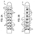
- Figs. 2a and 2b depict the perceived benefit of a flow enhancing tip used in combination with antimicrobial agents and/or drugs compared with antimicrobial agents and/or drugs not combined with a flow enhancing tip.
- tip 10 is shown with apertures 12 of varying cross-sectional area. As one proceeds from the distal end to the proximal end of tip 10, apertures 12 decrease in cross-sectional area. This aperture geometry helps to promote uniform flow which in turn is expected to promote uniform release of antimicrobial agents or drugs 14.
- FIG. 2b conventional tip 10 is shown with apertures 12 of constant cross-sectional area. Fluid flow entering through apertures 12 will not produce a uniform flow with tip 10 and therefore release of antimicrobial agents or drugs 14 is not expected to be uniform.
- Lin, supra discloses theoretical and experimental data showing that more than 80% of total fluid mass flows into the two most proximal holes of a hydrocephalus shunt.
- Catheters with variable sized holes, with its largest one situated at the catheter tip, would redistribute the flow more evenly along the entire length of the catheter. Therefore, favorable changes in the geometry of the proximal catheter can significantly alter the fluid dynamics of the catheter, which in itself may ultimately lead to a decrease in the rate of proximal catheter obstruction and when coupled with antimicrobial agents and/or drugs and provide more even release of the antimicrobial agents and/or drugs to more effectively combat bacterial biofilms and/or tissues proliferation.
- the present invention utilizes a hole geometry as depicted in Fig. 3 wherein the size of the holes progressively increase in cross-sectional area from the most proximal inlet hole to the most distal inlet hole.
- the flow enhancing tip may further comprise a porous device that is incorporated into or onto the tip to reduce the likelihood of blockage by tissue ingrowth.
- the device may also be used to dialyze the fluid surrounding the catheter. It is envisioned that the pores would be less than 5 ⁇ m in their largest dimension, and preferably less than 1 ⁇ m, to prevent tissue structures and a supporting blood supply from growing into the luminal space.
- the device may be attached to the outside surface of the catheter, or it may be inserted into the lumen. Alternatively, the device may be integrated into the catheter material in such a way as to produce a composite structure.
- the porous device may have pore sizes of subnano-, nano- or microporosity to selectively exclude blood vessels, cells, biological debris or molecules of a specific size from the lumen of the catheter.
- the purpose of the porous aspect of the device is also to prevent catheter obstruction due to tissue ingrowth.
- the device may also be used to dialyze the fluid surrounding the catheter.
- the porous device may be attached to the inside and/or outside surfaces of all or part of the catheter.
- the device may also be incorporated into the catheter material on may comprise a sleeve which fits over a catheter tip.
- the pore size is ideally less than 1 ⁇ m to prevent cellular migration into the lumen of the catheter and the development of tissue structures and a supporting blood supply.
- the porous device described in this invention may also be used to prevent blockage at the proximal or distal end of a hydrocephalus catheter, or at the outlet of a drug delivery catheter, or at the end of another fluid management catheter.
- the pore size of the device may also be chosen such that only molecules of a specific size range are allowed to pass into the catheter.
- the porous device may be fabricated from metal, ceramic, a selected bulk polymer or a polymer film.
- the pores may be created by manufacturing processes including but not limited to laser drilling, chemical etching, controlled sintering, or incorporating leachable additives or pore-forming agents.
- the fluid discharge from the devices of this invention may be to selected areas inside or outside of the human body.
- Typical selected discharge areas inside the human body include the peritoneum, the right atrium of the heart, the pleural cavity, and the bladder.
- the common selected discharge areas outside the human body include fluid collection chambers such as drainage bags.
- antimicrobial agents are intended to encompass those agents that prevent or minimize bacterial colonization and are intended to include but not be limited to antibiotics, antiseptics and disinfectants.
- antibiotics examples include tetracyclines (e.g., minocycline), rifamycins (e.g., rifampin), macrolides (e.g., erythromycin), penicillins (e.g., nafcillin), cephalosporins (e.g., cefazolin), other beta-lactam antibiotics (e.g., imipenem, aztreonam), aminoglycosides (e.g., gentamicin), chloramphenicol, sufonamides (e.g., sulfamethoxazole), glycopeptides (e.g., vancomycin), quinolones (e.g., ciprofloxacin), fusidic acid, trimethoprim, metronidazole, clindamycin, mupirocin, polyenes (e.g., amphotericin B), azoles (e.g., fluconazo
- antibiotics examples include minocycline, rifampin, erythromycin, nafcillin, cefazolin, imipenem, aztreonam, gentamicin, sulfamethoxazole, vancomycin, ciprofloxacin, trimethoprim, metronidazole, clindamycin, teicoplanin, mupirocin, azithromycin, clarithromycin, ofloxacin, lomefloxacin, norfloxacin, nalidixic acid, sparfloxacin, pefloxacin, amifloxacin, enoxacin, fleroxacin, temafloxacin, tosufloxacin, clinafloxacin, sulbactam, clavulanic acid, amphotericin B, fluconazole, itraconazole, ketoconazole, and nystatin.
- antiseptics and disinfectants examples include hexachlorophene, cationic bisiguanides (e.g., chlorhexidine, cyclohexidine) iodine and iodophores (e.g., povidone-iodine), para-chloro-meta-xylenol, triclosan, furan medical preparations (e.g., nitrofurantoin, nitrofurazone), methenamine, aldehydes (glutaraldehyde, formaldehyde) and alcohols.
- cationic bisiguanides e.g., chlorhexidine, cyclohexidine
- iodine and iodophores e.g., povidone-iodine
- para-chloro-meta-xylenol e.g., nitrofurazone
- furan medical preparations e.g., nitrofurantoin, nitrofurazone
- the most preferred antimicrobials are rifampin and clindamycin hydrochloride. Together they provide superior penetration and persistent antimicrobial activity in devices treated.
- the antimicrobial activity covers most strains of gram-positive bacteria causing the majority of infections in medical devices such as hydrocephalus shunts.
- drugs are intended to encompass drugs that prevent or minimize tissue growth whether the drugs are cytostatic drugs or cytotoxic drugs.
- Non-limitative examples of drugs include therapeutic and pharmaceutic agents including: anti-proliferative/antimitotic agents including natural products such as vinca alkaloids (e.g., vinblastine, vincristine, and vinorelbine), paclitaxel, epidipodophyllotoxins (e.g., etoposide, teniposide), antibiotics (dactinomycin (actinomycin D) daunorubicin, doxorubicin and idarubicin), anthracyclines, mitoxantrone, bleomycins, plicamycin (mithramycin) and mitomycin, enzymes (L-asparaginase which systemically metabolizes L-asparagine and deprives cells which do not have the capacity to synthesize their own asparagine); antiplatelet agents such as G(GP) 11 b /111 a inhibitors and vitronectin receptor antagonists; anti-proliferative/antimitotic alky
- a preferred cytostatic drug is sirolimus (rapamycin) particularly in combination with mycophenolic acid.
- a preferred cytotoxic drug is paclitaxel.
- Non-limiting examples of fluid flow control implants include shunts and hydrocephalus shunts.
- impregnation is preferred when dealing with medical devices made of polymeric materials such as silicone elastomers.
- the antimicrobial agent and/or drug may also be coated on the inside and/or outside surfaces of all or part of the implant.
- the drug may be incorporated into the catheter material such that it diffuses from the inside and/or outside surfaces of the tip of the catheter in the region where the fluid drainage holes are located.
- a porous or other type of sleeve, made from a material that contains the drug(s) may be placed over the outside and/or into the inside lumen of the proximal tip of the catheter in the region where the fluid drainage holes are located.
- the impregnation process can be altered to leave an antimicrobial agent and/or drug on the surface.
- a top-coat that can be used to modulate the elution profile from either the surface or the bulk of the catheter and/or localize the effect of the drug is also being explored.
- the top-coat can range from a monolayer to a thick layer of synthetic polymer or protein, carbohydrate, or glycoprotein.
- the coatings can comprise combinations of the previous classes of molecules.
- grafted molecules consisting of combinations of synthetic and natural polymers can be used in the form of dendrimers, star, comb or block copolymers.
- the top-coat can contain drug or could be drug free. Both hydrophilic and or hydrophobic synthetic polymers could be used.
- polyethylene oxide based polymer systems have been widely used as coatings as have fluorinated polymers and copolymers. Layered systems could provide special benefits. Heparin-based polymer systems as well as other sulfated proteoglycan systems (such as chondroitin sulfate) have also been widely used as coatings. Topcoats consisting of laminated layers of these constituents are also contemplated. Such topcoats could be used to reduce the rate of drug elution or provide an immediate burst of particular drugs.
- topcoats are also described here. These systems can consist of thicker topcoat layers in the vicinity of drainage orifices or have different materials printed in layers onto different points along the surface of the catheter tip. In addition, different drugs or different concentrations of drugs can be laid down at different points along the surface of the catheter tip. The goal would be to produce local effects at the orifices in the catheter tip and may be advantageous where very expensive drugs or polymer materials are being used.
- Antiomicrobial agents or drugs can be both physically entrapped as well as covalently grafted in the topcoat layers.
- Covalently grafted drugs would either inhibit cell attachment by interfering with cell membrane function or would be slowly released by cleavage of labile linkages. Cleavage could either be by chemical or proteolytic mechanisms.
- antimicrobial agent(s) and/or drug(s) are impregnated into the bulk of the catheter either by compounding-in the drug when the catheter is molded (if the drug is stable to this process) or by impregnating the catheter with drug post-molding. Impregnation can be accomplished by using a solvent or co-solvent system to swell the polymer and diffuse-in the antimicrobial agents/drugs, followed by evaporation of the solvents to entrap the antimicrobial agent/drugs. Impregnation by supercritical fluids or supercritical fluid-organic co-solvent fluids is also described to reduce the quantity of organic solvent needed.
- the advantage here is primarily ecological (reduced toxic pollutants), but also unique drug-polymer microstructures and release-profiles are possible.
- an antimicrobial agent/drug loading profile that varies through the thickness of the coating can be achieved. This type of process can provide higher surface concentrations of the antimicrobial agents/drugs.
- antimicrobial agents/drugs can also be included in a sprayed-on coating or dip-coated topcoat. Surface variable coatings can be achieved by masking the implants such as catheters in a spraying process or by selectively spraying only certain areas. Selective material layers can be added by sequentially building up different layers. Finally, coatings can be applied or modified using chemical vapor deposition or plasma coating processes. This can also be desirable for preventing delamination of laminated coatings.
Abstract
Description
- The present invention relates to fluid management flow devices, and in particular hydrocephalus shunts containing an antibiotic and/or drug to minimize the risk of blockage or obstruction inside of the catheter while improving protection against colonization of gram-positive bacteria and/or tissue proliferation when the devices are combined with uniform fluid flow enhancing tips.
- Hydrocephalus is a neurological condition that is caused by the abnormal accumulation of cerebrospinal fluid (CSF) within the ventricles, or cavities, of the brain. CSF is a clear, colorless fluid that is primarily produced by the choroid plexus and surrounds the brain and spinal cord. CSF constantly circulates through the ventricular system of the brain and is ultimately absorbed into the bloodstream. CSF aids in the protection of the brain and spinal cord. Because CSF keeps the brain and spinal cord buoyant, it acts as a protective cushion or "shock absorber" to prevent injuries to the central nervous system.
- Hydrocephalus, which affects children and adults, arises when the normal drainage of CSF in the brain is blocked in some way. Such blockage can be caused by a number of factors, including, for example, genetic predisposition, intraventricular or intracranial hemorrhage, infections such as meningitis, head trauma, or the like. Blockage of the flow of CSF consequently creates an imbalance between the amount of CSF produced by the choroid plexus and the rate at which CSF is absorbed into the bloodstream, thereby increasing pressure on the brain, which causes the ventricles to enlarge.
- Some of these problems can be treated by backflushing, which is a process that uses the CSF present in the shunt system to remove the obstructing matter. This process can be ineffective, however, due to the small size of the pores of the ventricular catheter and due to the small amount of flushing liquid available in the shunt system. Other shunt systems have been designed to include a mechanism for flushing the shunt system. For example, some shunt systems include a pumping device within the system which causes fluid in the system to flow with considerable pressure and velocity, thereby flushing the system. As with the process of backflushing, using a built-in mechanism to flush the shunt system can also fail to remove the obstruction due to factors such as the size of the pores and the degree and extent to which the pores have been clogged.
- Occluded ventricular catheters can also be repaired by cauterizing the catheter to remove blocking tissue, thereby reopening existing pores that have become occluded. Alternatively, new pores can be created in the catheter. These repairs, however, may be incapable of removing obstructions from the ventricular catheter depending on the location of the clogged pores. Additionally, the extent of tissue growth into and around the catheter can also preclude the creation of additional pores, for example, in situations where the tissue growth covers a substantial portion of the ventricular catheter. Another disadvantage of creating new apertures to repair an occluded ventricular catheter is that this method fails to prevent or reduce the risk of repeated obstructions.
- Because attempts at flushing or repairing a blocked ventricular catheter are often futile and ineffective, occlusion is more often treated by replacing the catheter. Although this can be accomplished by simply removing the obstructed catheter from the ventricle, the growth of the choroid plexus and other tissues around the catheter and into the pores can hinder removal and replacement of the catheter. Care must be exercised to avoid damage to the choroid plexus, which can cause severe injury to the patient, such as, for example, hemorrhaging. Not only do these procedures pose a significant risk of injury to the patient, they can also be very costly, especially when shunt obstruction is a recurring problem
-
US 4,917,686 , describes implanted medical devices (such catheters, valves, molded parts, etc. and including hydrocephalus shunts and central venous catheters) that have been treated with antimicrobial agents to combat the problem of colonization of bacteria particularly on the interior surfaces of the device. -
US 2003/0216710 , describes a catheter having one or more inlet holes along the length of the catheter whereby the cross-sectional areas of successive inlet holes decreases, the decrease first occurring at the inlet hole immediately following the most proximal inlet hole. Such a design purports to alter the typical inflow of fluid into the catheter such that a disproportionately high volume of fluid no longer enters the most proximal inlet hole. The decrease in inflow at the most proximal inlet results in less deposition of debris within the catheter at this position. - Lin et al., in "Computational and Experimental Study of Proximal Flow in Ventricular Catheters", (J. Neurosurgery 99:426-431, 2003), describes and demonstrates that drainage hole geometry is indeed a factor in achieving uniform flow patterns within ventricular catheters.
Fig. 2 of Lin dramatically demonstrates the flow distribution improvement when catheter hole geometry is modified. The problem addressed by Lin relates to obstructing agents such as blood clots, cell clusters and normal tissue as causing occlusion of the catheter at its proximal end. There is no mention of antimicrobial or drug based implantable medical devices such as catheters or shunts in an attempt to alleviate occlusion of the catheter lumen caused by biofilm formation through bacterial colonization or occlusion by tissue proliferation. - Accordingly, there exists a need for fluid management flow implants, such as shunts and catheter shunt systems that minimize or eliminate the risk of blockage or obstruction in the implant and reduces the possibility of bacterial biofilm or tissue occlusion within the lumens and inner surfaces of the implants.
-
WO2004/073768 describes a fluid flow management shunt comprising a drug-eluting drainage catheter. -
EP-A-1364628 describes a drug eluting coating that may be applied to a wide range of medical devices, including shunts for hydrocephalus. -
US-A-2004/0054351 describes an injection catheter for uniform delivery of a medication. The catheter has a flow distribution enhancing tip haying outlet apertures that progressively increase in cross-sectional area from the most proximal outlet aperture to the most distal outlet aperture. -
US-A-4950232 describes a catheter for a drainage of cerebrospinal fluid having a drainage tip in which the holes are protected against occlusion in a groove, allowing for an undisturbed flow of fluid. -
US-B-6533763 describes improved catheters for the removal and/or delivery of fluids to a patient, in particular for haemodialysis. The catheter may have outlet apertures that progressively increase in cross-sectional area from the most proximal inlet aperture to the most distal inlet aperture. -
WO94/07549 - The present invention provides a fluid flow management implant comprising: (a) an antimicrobial or drug-eluting drainage catheter comprising a proximal and distal end; characterized in that (b) an antimicrobial agent or a drug that prevents or minimizes tissue growth is coated on said catheter or impregnated in said catheter; and (c) a flow distribution enhancing tip is provided at the distal end of the catheter, wherein the flow distribution enhancing tip comprises a distal end which is sealed and a plurality of inlet apertures located between the distal and proximal ends of the tip, and the inlet apertures progressively increase in cross-sectional area from the most proximal inlet aperture to the most distal inlet aperture.
- The invention will now be described in more detail, with reference to the accompanying drawings, in which:
-
Fig. 1a depicts the first step in staphylococcal biofilm formation that of adhesion of staphylococcal cells to a surface. -
Fig. 1b depicts the second step in staphylococcal biofilm formation, that of multiplication of cells and production of a slime matrix. -
Fig. 2a and 2b depict a comparison showing the perceived benefits of antibiotic or drug release for a catheter with uniform fluid flow distribution through catheter holes compared with non-uniform fluid flow distribution. -
Fig. 3 depicts an embodiment of a fluid flow enhancing distribution tip. - The present invention is directed toward fluid management flow implants such as catheter drainage devices, preferably hydrocephalus shunts, which contain antibiotics to prevent or reduce the risk of infection and slime formation in the interior surfaces of the catheter and/or a drug to prevent or minimize tissue growth, combined with a flow distribution enhancing tip. This combination device will potentially minimize the risk of blockage or obstruction of the lumens and inner surfaces of the implants due to either biofilm formation or tissue in-growth and allow a greater chance of uninterrupted fluid flow which will in turn lessen the likelihood for costly revision surgery or procedures.
- Lundberg et al.: Presence of vitronectin and activated complement factor C9 on ventriculoperitoneal shunts and temporary ventricular drainage catheters. J Neurosurg 1999, 90: 101-108 and Bayston & Penny:
- Excessive production of mucoid substance by Staphylococcus SIIA: a possible factor in colonization of Holter shunts. Dev Med Child Neurol 1972: 14 Suppl 27: 25-28 recognized that adhesion of bacteria to an implant surface is a critical initial step in the development of biomaterial-centered infections. Also, F. Gotz and G. Peters: Colonization of Medical Devices by Coagulase-Negative Staphylococci. In: Infections Associated with Indwelling Medical Devices. F.A. Waldvogel and A.L. Bisno eds., ASM Press, Washington, DC, 2000, p. 69. report that ventricular CSF cultures in patients with symptoms of shunt infection are frequently negative and the shunt cultures are positive, indicating shunt colonization is a key element of shunt-related infections. The primary adhesion event is mediated by binding proteins on the bacterial surface. Bactiseal catheters are specifically designed to provide extended protection from colonization of the silicone surface by coagulase-negative bacteria such as S epidermidis.
-
Figs. 1a and 1b describe the above described two step model of biofilm formation.Fig. 1a shows the first step in biofilm formation which is the adherence of thebacterial cells 2 to a surface 1. InFig. 1b , the second step is the imbedding of thecells 2 into a thick slime matrix (biofilm) 3. - The flow distribution enhancing tip enables uniform flow patterns within the medical device. The terms "uniform flow pattern" or "uniform flow distribution" are intended to describe a tip which improves fluid flow over tips not so designed. By providing more uniform fluid flow in the implants, particularly with in the lumens of catheters and hydrocephalus shunts, more uniform release of antimicrobial agents and drugs are achieved which in turn should provide improved resistance to flow occlusion caused by bacterial biofilms and tissue proliferation.
-
Figs. 2a and 2b depict the perceived benefit of a flow enhancing tip used in combination with antimicrobial agents and/or drugs compared with antimicrobial agents and/or drugs not combined with a flow enhancing tip. - Referring to
Fig. 2a ,tip 10 is shown withapertures 12 of varying cross-sectional area. As one proceeds from the distal end to the proximal end oftip 10,apertures 12 decrease in cross-sectional area. This aperture geometry helps to promote uniform flow which in turn is expected to promote uniform release of antimicrobial agents ordrugs 14. - In contrast, and now referring to
Fig. 2b ,conventional tip 10 is shown withapertures 12 of constant cross-sectional area. Fluid flow entering throughapertures 12 will not produce a uniform flow withtip 10 and therefore release of antimicrobial agents ordrugs 14 is not expected to be uniform. - Examples of suitable flow distribution enhancing tips may be found. For example, in
US 2003/0216710 and Lin, supra. - More specifically, Lin, supra, discloses theoretical and experimental data showing that more than 80% of total fluid mass flows into the two most proximal holes of a hydrocephalus shunt. Catheters with variable sized holes, with its largest one situated at the catheter tip, would redistribute the flow more evenly along the entire length of the catheter. Therefore, favorable changes in the geometry of the proximal catheter can significantly alter the fluid dynamics of the catheter, which in itself may ultimately lead to a decrease in the rate of proximal catheter obstruction and when coupled with antimicrobial agents and/or drugs and provide more even release of the antimicrobial agents and/or drugs to more effectively combat bacterial biofilms and/or tissues proliferation. Thus, the present invention utilizes a hole geometry as depicted in
Fig. 3 wherein the size of the holes progressively increase in cross-sectional area from the most proximal inlet hole to the most distal inlet hole. - In one embodiment, the flow enhancing tip may further comprise a porous device that is incorporated into or onto the tip to reduce the likelihood of blockage by tissue ingrowth. The device may also be used to dialyze the fluid surrounding the catheter. It is envisioned that the pores would be less than 5 µm in their largest dimension, and preferably less than 1 µm, to prevent tissue structures and a supporting blood supply from growing into the luminal space. The device may be attached to the outside surface of the catheter, or it may be inserted into the lumen. Alternatively, the device may be integrated into the catheter material in such a way as to produce a composite structure.
- The porous device may have pore sizes of subnano-, nano- or microporosity to selectively exclude blood vessels, cells, biological debris or molecules of a specific size from the lumen of the catheter. The purpose of the porous aspect of the device is also to prevent catheter obstruction due to tissue ingrowth. The device may also be used to dialyze the fluid surrounding the catheter.
- The porous device may be attached to the inside and/or outside surfaces of all or part of the catheter. The device may also be incorporated into the catheter material on may comprise a sleeve which fits over a catheter tip. The pore size is ideally less than 1 µm to prevent cellular migration into the lumen of the catheter and the development of tissue structures and a supporting blood supply. The porous device described in this invention may also be used to prevent blockage at the proximal or distal end of a hydrocephalus catheter, or at the outlet of a drug delivery catheter, or at the end of another fluid management catheter. The pore size of the device may also be chosen such that only molecules of a specific size range are allowed to pass into the catheter.
- The porous device may be fabricated from metal, ceramic, a selected bulk polymer or a polymer film. The pores may be created by manufacturing processes including but not limited to laser drilling, chemical etching, controlled sintering, or incorporating leachable additives or pore-forming agents.
- The fluid discharge from the devices of this invention may be to selected areas inside or outside of the human body. Typical selected discharge areas inside the human body include the peritoneum, the right atrium of the heart, the pleural cavity, and the bladder. The common selected discharge areas outside the human body include fluid collection chambers such as drainage bags.
- As used herein, antimicrobial agents are intended to encompass those agents that prevent or minimize bacterial colonization and are intended to include but not be limited to antibiotics, antiseptics and disinfectants.
- Examples of suitable antibiotics include tetracyclines (e.g., minocycline), rifamycins (e.g., rifampin), macrolides (e.g., erythromycin), penicillins (e.g., nafcillin), cephalosporins (e.g., cefazolin), other beta-lactam antibiotics (e.g., imipenem, aztreonam), aminoglycosides (e.g., gentamicin), chloramphenicol, sufonamides (e.g., sulfamethoxazole), glycopeptides (e.g., vancomycin), quinolones (e.g., ciprofloxacin), fusidic acid, trimethoprim, metronidazole, clindamycin, mupirocin, polyenes (e.g., amphotericin B), azoles (e.g., fluconazole) and beta-lactam inhibitors (e.g., sulbactam).
- Examples of preferred antibiotics include minocycline, rifampin, erythromycin, nafcillin, cefazolin, imipenem, aztreonam, gentamicin, sulfamethoxazole, vancomycin, ciprofloxacin, trimethoprim, metronidazole, clindamycin, teicoplanin, mupirocin, azithromycin, clarithromycin, ofloxacin, lomefloxacin, norfloxacin, nalidixic acid, sparfloxacin, pefloxacin, amifloxacin, enoxacin, fleroxacin, temafloxacin, tosufloxacin, clinafloxacin, sulbactam, clavulanic acid, amphotericin B, fluconazole, itraconazole, ketoconazole, and nystatin.
- Examples of antiseptics and disinfectants are hexachlorophene, cationic bisiguanides (e.g., chlorhexidine, cyclohexidine) iodine and iodophores (e.g., povidone-iodine), para-chloro-meta-xylenol, triclosan, furan medical preparations (e.g., nitrofurantoin, nitrofurazone), methenamine, aldehydes (glutaraldehyde, formaldehyde) and alcohols.
- The most preferred antimicrobials are rifampin and clindamycin hydrochloride. Together they provide superior penetration and persistent antimicrobial activity in devices treated. The antimicrobial activity covers most strains of gram-positive bacteria causing the majority of infections in medical devices such as hydrocephalus shunts.
- As used herein, the term drugs are intended to encompass drugs that prevent or minimize tissue growth whether the drugs are cytostatic drugs or cytotoxic drugs.
- Non-limitative examples of drugs include therapeutic and pharmaceutic agents including: anti-proliferative/antimitotic agents including natural products such as vinca alkaloids (e.g., vinblastine, vincristine, and vinorelbine), paclitaxel, epidipodophyllotoxins (e.g., etoposide, teniposide), antibiotics (dactinomycin (actinomycin D) daunorubicin, doxorubicin and idarubicin), anthracyclines, mitoxantrone, bleomycins, plicamycin (mithramycin) and mitomycin, enzymes (L-asparaginase which systemically metabolizes L-asparagine and deprives cells which do not have the capacity to synthesize their own asparagine); antiplatelet agents such as G(GP) 11b/111a inhibitors and vitronectin receptor antagonists; anti-proliferative/antimitotic alkylating agents such as nitrogen mustards (mechlorethamine, cyclophosphamide and analogs, melphalan, chlorambucil), ethylenimines and methylmelamines (hexamethylmelamine and thiotepa), alkyl sulfonates-busulfan, nirtosoureas (carmustine (BCNU) and analogs, streptozocin), trazenes - dacarbazinine (DTIC); anti-proliferative/antimitotic antimetabolites such as folic acid analogs (methotrexate), pyrimidine analogs (fluorouracil, floxuridine, and cytarabine), purine analogs and related inhibitors (mercaptopurine, thioguanine, pentostatin and 2-chlorodeoxyadenosine {cladribine}); platinum coordination complexes (cisplatin, carboplatin), procarbazine, hydroxyurea, mitotane, aminoglutethimide; hormones (e.g., estrogen); anti-coagulants (heparin, synthetic heparin salts and other inhibitors of thrombin); fibrinolytic agents (such as tissue plasminogen activator, streptokinase and urokinase), aspirin, dipyridamole, ticlopidine, clopidogrel, abciximab; antimigratory; antisecretory (breveldin); anti-inflammatory: such as adrenocortical steroids (cortisol, cortisone, fludrocortisone, prednisone, prednisolone, 6α-methylprednisolone, triamcinolone, betamethasone, and dexamethasone), non-steroidal agents salicylic acid derivatives e.g., aspirin; para-aminophenol derivatives e.g., acetaminophen; indole and indene acetic acids (indomethacin, sulindac, and etodalac), heteroaryl acetic acids (tolmetin, diclofenac, and ketorolac), arylpropionic acids (ibuprofen and derivatives), anthranilic acids (mefenamic acid, and meclofenamic acid), mycophenolic acids, enolic acids (piroxicam, tenoxicam, phenylbutazone, and oxyphenthatrazone), nabumetone, gold compounds (auranofin, aurothioglucose, gold sodium thiomalate); immunosuppressives: (cyclosporine, tacrolimus (FK-506), sirolimus (rapamycin), azathioprine, mycophenolate mofetil); angiogenic agents: vascular endothelial growth factor (VEGF), fibroblast growth factor (FGF); angiotensin receptor blockers; nitric oxide donors; antisense oligionucleotides and combinations thereof; cell cycle inhibitors, mTOR inhibitors, and growth factor receptor signal transduction kinase inhibitors; retenoids; cyclin/CDK inhibitors; HMG co-enzyme reductase inhibitors (statins); and protease inhibitors.
- A preferred cytostatic drug is sirolimus (rapamycin) particularly in combination with mycophenolic acid.
- A preferred cytotoxic drug is paclitaxel.
- Non-limiting examples of fluid flow control implants include shunts and hydrocephalus shunts.
- While many types of methods may be used to combine an antimicrobial agent or drug with the fluid flow control system of the present invention such as by coating or impregnation, impregnation is preferred when dealing with medical devices made of polymeric materials such as silicone elastomers.
-
U.S. Patent 4,917,686 describes a preferred method of incorporating antimicrobial agents within medical devices. - The antimicrobial agent and/or drug may also be coated on the inside and/or outside surfaces of all or part of the implant. The drug may be incorporated into the catheter material such that it diffuses from the inside and/or outside surfaces of the tip of the catheter in the region where the fluid drainage holes are located. Alternatively, a porous or other type of sleeve, made from a material that contains the drug(s) may be placed over the outside and/or into the inside lumen of the proximal tip of the catheter in the region where the fluid drainage holes are located.
- The impregnation process can be altered to leave an antimicrobial agent and/or drug on the surface. A top-coat that can be used to modulate the elution profile from either the surface or the bulk of the catheter and/or localize the effect of the drug is also being explored. The top-coat can range from a monolayer to a thick layer of synthetic polymer or protein, carbohydrate, or glycoprotein. The coatings can comprise combinations of the previous classes of molecules. In addition, grafted molecules consisting of combinations of synthetic and natural polymers can be used in the form of dendrimers, star, comb or block copolymers. The top-coat can contain drug or could be drug free. Both hydrophilic and or hydrophobic synthetic polymers could be used. For example polyethylene oxide based polymer systems have been widely used as coatings as have fluorinated polymers and copolymers. Layered systems could provide special benefits. Heparin-based polymer systems as well as other sulfated proteoglycan systems (such as chondroitin sulfate) have also been widely used as coatings. Topcoats consisting of laminated layers of these constituents are also contemplated. Such topcoats could be used to reduce the rate of drug elution or provide an immediate burst of particular drugs.
- Spatially unhomogeneous topcoats are also described here. These systems can consist of thicker topcoat layers in the vicinity of drainage orifices or have different materials printed in layers onto different points along the surface of the catheter tip. In addition, different drugs or different concentrations of drugs can be laid down at different points along the surface of the catheter tip. The goal would be to produce local effects at the orifices in the catheter tip and may be advantageous where very expensive drugs or polymer materials are being used.
- Antiomicrobial agents or drugs can be both physically entrapped as well as covalently grafted in the topcoat layers. Covalently grafted drugs would either inhibit cell attachment by interfering with cell membrane function or would be slowly released by cleavage of labile linkages. Cleavage could either be by chemical or proteolytic mechanisms.
- Numerous processes for depositing drug or coatings may be used in conjunction with this invention. Most simply, antimicrobial agent(s) and/or drug(s) are impregnated into the bulk of the catheter either by compounding-in the drug when the catheter is molded (if the drug is stable to this process) or by impregnating the catheter with drug post-molding. Impregnation can be accomplished by using a solvent or co-solvent system to swell the polymer and diffuse-in the antimicrobial agents/drugs, followed by evaporation of the solvents to entrap the antimicrobial agent/drugs. Impregnation by supercritical fluids or supercritical fluid-organic co-solvent fluids is also described to reduce the quantity of organic solvent needed. The advantage here is primarily ecological (reduced toxic pollutants), but also unique drug-polymer microstructures and release-profiles are possible. By limiting the exposure time of the catheter to the antimicrobial agent/drug-solvent solution, an antimicrobial agent/drug loading profile that varies through the thickness of the coating can be achieved. This type of process can provide higher surface concentrations of the antimicrobial agents/drugs. In addition to depositing the antimicrobial agents/drugs in the bulk of the catheter, antimicrobial agents/drugs can also be included in a sprayed-on coating or dip-coated topcoat. Surface variable coatings can be achieved by masking the implants such as catheters in a spraying process or by selectively spraying only certain areas. Selective material layers can be added by sequentially building up different layers. Finally, coatings can be applied or modified using chemical vapor deposition or plasma coating processes. This can also be desirable for preventing delamination of laminated coatings.
Claims (10)
- A fluid flow management implant comprising:a) an antimicrobial or drug-eluting drainage catheter comprising a proximal and distal end; characterized in thatb) an antimicrobial agent or a drug that prevents or minimizes tissue growth is coated on said catheter or impregnated in said catheter; andc) a flow distribution enhancing tip (10) is provided at the distal end of the catheter, wherein the flow distribution enhancing tip (10) comprises a distal end which is sealed and a plurality of inlet apertures (12) located between the distal and proximal ends of the tip (10), and the inlet apertures (12) progressively increase in cross-sectional area from the most proximal inlet aperture to the most distal inlet aperture.
- The implant of claim 1, wherein the implant is a shunt.
- The implant of claim 2, wherein the implant is a hydrocephalus shunt.
- The implant of claim 1, wherein the catheter is coated or impregnated with antimicrobial agents selected from the group consisting of tetracyclines, rifamycins, macrolides, penicillins, cephalosporins, other beta-lactam antibiotics, aminoglycosides, chloramphenicol, sufonamides, glycopeptides, quinolones, fusidic acid, trimethoprim, metronidazole, clindamycins, mupirocin, polyenes, azoles, beta-lactam inhibitors and mixtures thereof.
- The implant of claim 4, wherein the antimicrobial agent is selected from the group consisting of isminocycline, rifampin, erythromycin, nafcillin, cefazolin, imipenem, aztreonam, gentamicin, sulfamethoxazole, vancomycin, ciprofloxacin, trimethoprim, metronidazole, clindamycin, teicoplanin, mupirocin, azithromycin, clarithromycin, ofloxacin, lomefloxacin, norfloxacin, nalidixic acid, sparfloxacin, pefloxacin, amifloxacin, enoxacin, fleroxacin, temafloxacin, tosufloxacin, clinafloxacin, sulbactam, clavulanic acid, amphotericin B, fluconazole, itraconazole, ketoconazole, nystatin and mixtures thereof.
- The implant of claim 4, wherein the antimicrobial agent is selected from the group consisting of rifampin, clindamycin hydrochloride and mixtures thereof.
- The implant of claim 1, wherein the drug coated or impregnated in the drug-eluting catheter comprises a drug selected from the group consisting of vinca alkaloids, paclitaxel, epidipodophyllotoxins, anthracyclines, mitoxantrone, bleomycins, plicamycin (mithramycin) and mitomycin, enzymes; antiplatelet agents; antiproliferative/antimitotic alkylating agents; anti-proliferative/antimitotic antimetabolites; platinum coordination complexes; hormones; anti-coagulants; fibrinolytic agents; antiinflammatory steriods, non-steroidal agents; para-aminophenol derivatives; indole and indene acetic acids, heteroaryl acetic acids, mycophenolic acids, enolic acids, nabumetone, gold compounds; immunosuppressives; sirolimus (rapamycin), azathioprine, mycophenolate mofetil); angiogenic agents: vascular endothelial growth factor (VEGF), fibroblast growth factor (FGF); angiotensin receptor blockers; nitric oxide donors; antisense oligionucleotides and combinations thereof; cell cycle inhibitors, mTOR inhibitors, and growth factor receptor signal transduction kinase inhibitors; retenoids; cyclin/CDK inhibitors; HMG co-enzyme reductase inhibitors (statins); protease inhibitors and mixtures thereof.
- The implant of claim 7, wherein the drug comprises paclitaxel.
- The implant of claim 7, wherein the drug comprises a combination of sirolimus and mycophenolic acid.
- The implant of claim 7, wherein the drug comprises sirolimus.
Applications Claiming Priority (1)
| Application Number | Priority Date | Filing Date | Title |
|---|---|---|---|
| US10/955,776 US7976517B2 (en) | 2004-09-30 | 2004-09-30 | Fluid management flow implants of improved occlusion resistance |
Publications (3)
| Publication Number | Publication Date |
|---|---|
| EP1649880A2 EP1649880A2 (en) | 2006-04-26 |
| EP1649880A3 EP1649880A3 (en) | 2007-09-26 |
| EP1649880B1 true EP1649880B1 (en) | 2010-10-27 |
Family
ID=35794941
Family Applications (1)
| Application Number | Title | Priority Date | Filing Date |
|---|---|---|---|
| EP05256107A Active EP1649880B1 (en) | 2004-09-30 | 2005-09-29 | Fluid management flow implants of improved occlusion resistance |
Country Status (8)
| Country | Link |
|---|---|
| US (2) | US7976517B2 (en) |
| EP (1) | EP1649880B1 (en) |
| JP (1) | JP5701469B2 (en) |
| AT (1) | ATE485846T1 (en) |
| AU (1) | AU2005204329B2 (en) |
| CA (1) | CA2521884C (en) |
| DE (1) | DE602005024352D1 (en) |
| ES (1) | ES2353221T3 (en) |
Families Citing this family (50)
| Publication number | Priority date | Publication date | Assignee | Title |
|---|---|---|---|---|
| US9694166B2 (en) * | 2002-03-26 | 2017-07-04 | Medtronics Ps Medical, Inc. | Method of draining cerebrospinal fluid |
| US20030216710A1 (en) * | 2002-03-26 | 2003-11-20 | Hurt Robert F. | Catheter |
| ES2490610T3 (en) * | 2004-12-08 | 2014-09-04 | Shire Regenerative Medicine, Inc. | Materials and methods for minimally invasive administration of a fluid composition containing cells |
| US8002730B2 (en) | 2005-04-29 | 2011-08-23 | Medtronic, Inc. | Anti-thrombogenic venous shunt system and method |
| US20080082036A1 (en) * | 2006-04-25 | 2008-04-03 | Medtronic, Inc. | Cerebrospinal fluid shunt having long term anti-occlusion agent delivery |
| JP2010005282A (en) * | 2008-06-30 | 2010-01-14 | Sumitomo Bakelite Co Ltd | Medical drain tube |
| AU2009293176B2 (en) * | 2008-09-18 | 2015-07-02 | Solventum Intellectual Properties Company | A system and method for delivering reduced pressure to subcutaneous tissue |
| US20100106161A1 (en) * | 2008-10-23 | 2010-04-29 | Marwan Tabbara | Surgical methods, devices, and kits |
| US9433209B2 (en) | 2009-03-26 | 2016-09-06 | Organic Medical Ventures, L.L.C. | Transdermal venous access locking solutions |
| US9427498B2 (en) | 2009-03-26 | 2016-08-30 | Organic Medical Ventures, L.L.C. | Syringe treated with transdermal venous access locking solutions and method of treating the syringe |
| US20100249747A1 (en) * | 2009-03-26 | 2010-09-30 | Organic Medical Ventures, L.L.C. | Transdermal venous access locking solution |
| US9072296B2 (en) | 2009-03-26 | 2015-07-07 | Organic Medical Ventures, L.L.C. | Transdermal venous access locking solutions |
| US8092443B2 (en) | 2009-03-30 | 2012-01-10 | Medtronic, Inc. | Element for implantation with medical device |
| EP3037102A1 (en) * | 2009-11-23 | 2016-06-29 | Stephen F. Olmstead | Compositions and methods comprising serratia peptidase for inhibition and treatment of biofilms related to certain conditions |
| CN106075698B (en) * | 2010-03-30 | 2020-02-21 | 火花医学研究有限公司 | Drug releasing medical catheters, tubes and devices |
| JP5820877B2 (en) | 2010-06-18 | 2015-11-24 | テクニオン リサーチ アンド ディベロップメント ファンデーション リミテッド | Self-cleaning shunt |
| US8702678B2 (en) * | 2011-08-03 | 2014-04-22 | Venous Therapy, Inc. | Assemblies, systems, and methods for infusing therapeutic agents into the body |
| HUE040153T2 (en) | 2011-08-31 | 2019-02-28 | Organic Medical Ventures L L C | Transdermal venous access locking solutions |
| EP2747831A4 (en) * | 2011-09-30 | 2015-08-12 | Sparkmed Res Llc | Systems, devices, and methods for embedding drug molecules into medical catheters or tubes |
| US20130102999A1 (en) * | 2011-10-25 | 2013-04-25 | Anthony M. Looper | Pleurodesis catheter with coated and shielded tip |
| US9227043B2 (en) | 2011-11-18 | 2016-01-05 | Washington University | Catheter assembly for use with shunt systems and method of using same |
| EP3453420A1 (en) | 2013-01-22 | 2019-03-13 | Anuncia, Inc. | Device for flushing a shunting system |
| US9682218B2 (en) | 2013-12-23 | 2017-06-20 | Carefusion 2200, Inc. | Pleurodesis device and method |
| ES2519940B1 (en) * | 2014-03-06 | 2015-10-22 | Universidad Miguel Hernández De Elche | Catheter for hydrocephalus treatment |
| WO2015161306A1 (en) | 2014-04-18 | 2015-10-22 | Alcyone Lifesciences, Inc. | Systems and methods for shunting fluid |
| US10926062B2 (en) | 2015-07-20 | 2021-02-23 | Strataca Systems Limited | Ureteral and bladder catheters and methods of inducing negative pressure to increase renal perfusion |
| MX2018000823A (en) | 2015-07-20 | 2018-05-15 | Ureteral and bladder catheters and methods for inducing negative pressure to increase renal perfusion. | |
| US11040180B2 (en) | 2015-07-20 | 2021-06-22 | Strataca Systems Limited | Systems, kits and methods for inducing negative pressure to increase renal function |
| US11541205B2 (en) | 2015-07-20 | 2023-01-03 | Roivios Limited | Coated urinary catheter or ureteral stent and method |
| US10512713B2 (en) | 2015-07-20 | 2019-12-24 | Strataca Systems Limited | Method of removing excess fluid from a patient with hemodilution |
| US10918827B2 (en) | 2015-07-20 | 2021-02-16 | Strataca Systems Limited | Catheter device and method for inducing negative pressure in a patient's bladder |
| US10493232B2 (en) | 2015-07-20 | 2019-12-03 | Strataca Systems Limited | Ureteral catheters, bladder catheters, systems, kits and methods for inducing negative pressure to increase renal function |
| US11229771B2 (en) | 2015-07-20 | 2022-01-25 | Roivios Limited | Percutaneous ureteral catheter |
| US11040172B2 (en) | 2015-07-20 | 2021-06-22 | Strataca Systems Limited | Ureteral and bladder catheters and methods of inducing negative pressure to increase renal perfusion |
| US10765834B2 (en) | 2015-07-20 | 2020-09-08 | Strataca Systems Limited | Ureteral and bladder catheters and methods of inducing negative pressure to increase renal perfusion |
| CN110099701B (en) | 2016-10-13 | 2022-04-12 | 安嫩西亚公司 | Shunt flusher and related methods |
| US10518069B2 (en) | 2016-10-28 | 2019-12-31 | Integra LifeSciences Switzerland Sarl | Implantable valve assembly with extended lifespan |
| US11439798B2 (en) | 2017-04-24 | 2022-09-13 | Longeviti Neuro Solutions Llc | Cerebral spinal fluid shunt plug |
| US11045632B2 (en) | 2017-04-24 | 2021-06-29 | Longeviti Neuro Solutions Llc | Cerebral spinal fluid shunt plug |
| US11284939B2 (en) * | 2017-07-06 | 2022-03-29 | Biosense Webster (Israel) Ltd. | Irrigated catheter with improved ablation tip electrode fluid distribution |
| CN107320839B (en) * | 2017-07-26 | 2023-03-17 | 常州瑞神安医疗器械有限公司 | In-vivo drainage device and method |
| EP3672656A1 (en) * | 2017-08-25 | 2020-07-01 | Strataca Systems Limited | Ureteral and bladder catheters and methods of inducing negative pressure to increase renal perfusion |
| CN110201174B (en) * | 2019-05-14 | 2021-08-03 | 青岛大学附属医院 | Pharmaceutical composition capable of resisting chronic infection and biofilm bacteria and application thereof |
| WO2021016579A1 (en) * | 2019-07-25 | 2021-01-28 | Minnetronix Neuro, Inc. | Systems for processing of cerebrospinal fluid |
| US20230001165A1 (en) * | 2019-11-20 | 2023-01-05 | Massachusetts Institute Of Technology | Cerebrospinal fluid space draining catheters |
| JP7029005B1 (en) | 2021-02-02 | 2022-03-02 | 厚夫 森 | catheter |
| WO2023039551A2 (en) * | 2021-09-09 | 2023-03-16 | Wayne State University | Methods and compositions to reduce cellular deposition, and hydrocephalus shunt failure |
| ES2952142B2 (en) * | 2022-03-21 | 2024-03-12 | Univ Miguel Hernandez De Elche | VENTRICULAR CATHETER FOR APPLICATION IN HYDROCEPHALUS TREATMENTS |
| WO2024047081A1 (en) | 2022-09-02 | 2024-03-07 | Universiteit Gent | Catheter for delivery of therapeutic liquid formulation |
| CN115814176A (en) * | 2022-12-13 | 2023-03-21 | 湛江市事达实业有限公司 | Flow guide pipe and disinfection method thereof |
Family Cites Families (32)
| Publication number | Priority date | Publication date | Assignee | Title |
|---|---|---|---|---|
| US3601128A (en) | 1968-12-26 | 1971-08-24 | Salomon Hakim | Ventriculoatrial shunt accumulator |
| US3669116A (en) | 1970-07-06 | 1972-06-13 | Heyer Schulte Corp | Drainage catheter with anticlogging means |
| US3690323A (en) | 1970-12-01 | 1972-09-12 | Us Army | Device for draining ventricular fluid in cases of hydrocephalus |
| US3894541A (en) | 1974-02-27 | 1975-07-15 | El Shafei Ismail Lotfy | Method of treating hydrocephalus |
| JPS5345083A (en) | 1976-10-05 | 1978-04-22 | Tokyo Ika Shika Daigakuchiyou | Silicon double tract for discharging fluid |
| US4377169A (en) | 1981-06-10 | 1983-03-22 | Banks Bruce A | Ion beam sputter-etched ventricular catheter for hydrocephalus shunt |
| US4655745A (en) | 1985-07-29 | 1987-04-07 | Corbett Joseph E | Ventricular catheter |
| JPS63501932A (en) * | 1985-12-16 | 1988-08-04 | デンバ− サ−ジカル デイベロツプメンツ インコ−ポレ−テツド | Antibacterial catheter and its method |
| US4917686A (en) * | 1985-12-16 | 1990-04-17 | Colorado Biomedical, Inc. | Antimicrobial device and method |
| US4950232A (en) | 1987-08-11 | 1990-08-21 | Surelab Superior Research Laboratories | Cerebrospinal fluid shunt system |
| US5180387A (en) | 1987-09-17 | 1993-01-19 | Neurodynamics, Inc. | Angled hole ventricular catheter with non-circular bore |
| US4767400A (en) | 1987-10-27 | 1988-08-30 | Cordis Corporation | Porous ventricular catheter |
| US5451215A (en) | 1990-09-17 | 1995-09-19 | Wolter; Dietmar | Suction drain for the aspiration of discharges |
| US5380307A (en) | 1992-09-30 | 1995-01-10 | Target Therapeutics, Inc. | Catheter with atraumatic drug delivery tip |
| US5405316A (en) | 1993-11-17 | 1995-04-11 | Magram; Gary | Cerebrospinal fluid shunt |
| US5579774A (en) | 1994-03-07 | 1996-12-03 | Camino Neurocare, Inc. | Method and apparatus for monitoring local cerebral physiology |
| US5531673A (en) | 1995-05-26 | 1996-07-02 | Helenowski; Tomasz K. | Ventricular catheter |
| US6110155A (en) | 1996-04-30 | 2000-08-29 | Medtronic, Inc. | Anti-inflammatory-agent-loaded catheter and method for preventing tissue fibrosis |
| US7510550B2 (en) | 1999-07-19 | 2009-03-31 | I-Flow Corporation | Catheter for uniform delivery of medication |
| US6350253B1 (en) | 1999-07-19 | 2002-02-26 | I-Flow Corporation | Catheter for uniform delivery of medication |
| US6325815B1 (en) | 1999-09-21 | 2001-12-04 | Microvena Corporation | Temporary vascular filter |
| US6533763B1 (en) | 1999-12-06 | 2003-03-18 | James A. Schneiter | Harmonic flow catheter |
| AU4567101A (en) | 2000-03-10 | 2001-09-24 | Macropore Inc | Resorbable micro-membrane for attenuation of scar tissue |
| US7419678B2 (en) | 2000-05-12 | 2008-09-02 | Cordis Corporation | Coated medical devices for the prevention and treatment of vascular disease |
| US6571125B2 (en) * | 2001-02-12 | 2003-05-27 | Medtronic, Inc. | Drug delivery device |
| US6969373B2 (en) | 2001-04-13 | 2005-11-29 | Tricardia, Llc | Syringe system |
| US6524268B2 (en) | 2001-06-12 | 2003-02-25 | George M. Hayner | Combination ureteral infusion catheter/drainage stent |
| WO2003020736A1 (en) * | 2001-08-28 | 2003-03-13 | Pharmacia Corporation | Crystaline clindamycin free base |
| US20030216710A1 (en) | 2002-03-26 | 2003-11-20 | Hurt Robert F. | Catheter |
| JP2006517850A (en) | 2003-02-18 | 2006-08-03 | メドトロニック・インコーポレーテッド | Occlusion resistant hydrocephalus shunt |
| US20040253281A1 (en) * | 2003-06-12 | 2004-12-16 | Atrium Medical Corp. | Therapeutic markings applied to tissue |
| US7553625B2 (en) * | 2003-12-22 | 2009-06-30 | John Wayne Cancer Institute | Method and apparatus for in vivo collection of circulating biological components |
-
2004
- 2004-09-30 US US10/955,776 patent/US7976517B2/en active Active
-
2005
- 2005-08-29 AU AU2005204329A patent/AU2005204329B2/en active Active
- 2005-09-29 EP EP05256107A patent/EP1649880B1/en active Active
- 2005-09-29 AT AT05256107T patent/ATE485846T1/en not_active IP Right Cessation
- 2005-09-29 DE DE602005024352T patent/DE602005024352D1/en active Active
- 2005-09-29 CA CA2521884A patent/CA2521884C/en active Active
- 2005-09-29 JP JP2005284791A patent/JP5701469B2/en active Active
- 2005-09-29 ES ES05256107T patent/ES2353221T3/en active Active
-
2007
- 2007-10-31 US US11/931,024 patent/US8221392B2/en active Active
Non-Patent Citations (1)
| Title |
|---|
| LIN J. ET AL: "Computational and experimental study of proximal flow in ventricular catheters", JOURNAL OF NEUROSURGERY, vol. 99, 2003, pages 426 - 431, XP008082562 * |
Also Published As
| Publication number | Publication date |
|---|---|
| EP1649880A2 (en) | 2006-04-26 |
| US7976517B2 (en) | 2011-07-12 |
| ES2353221T3 (en) | 2011-02-28 |
| US8221392B2 (en) | 2012-07-17 |
| JP2006110339A (en) | 2006-04-27 |
| DE602005024352D1 (en) | 2010-12-09 |
| CA2521884A1 (en) | 2006-03-30 |
| AU2005204329B2 (en) | 2011-07-21 |
| AU2005204329A1 (en) | 2006-04-13 |
| US20080214982A1 (en) | 2008-09-04 |
| EP1649880A3 (en) | 2007-09-26 |
| US20060074388A1 (en) | 2006-04-06 |
| CA2521884C (en) | 2015-01-13 |
| JP5701469B2 (en) | 2015-04-15 |
| ATE485846T1 (en) | 2010-11-15 |
Similar Documents
| Publication | Publication Date | Title |
|---|---|---|
| EP1649880B1 (en) | Fluid management flow implants of improved occlusion resistance | |
| EP1596895B1 (en) | Occlusion resistant hydrocephalic shunt | |
| US11623073B2 (en) | Cerebrospinal fluid shunt having long term anti-occlusion agent delivery | |
| WO2006029301A2 (en) | Method of manufacturing drug-eluting medical device | |
| EP2073852A2 (en) | Two part antimicrobial boot | |
| CA2794005C (en) | Adjusting drug loading in polymeric materials |
Legal Events
| Date | Code | Title | Description |
|---|---|---|---|
| PUAI | Public reference made under article 153(3) epc to a published international application that has entered the european phase |
Free format text: ORIGINAL CODE: 0009012 |
|
| AK | Designated contracting states |
Kind code of ref document: A2 Designated state(s): AT BE BG CH CY CZ DE DK EE ES FI FR GB GR HU IE IS IT LI LT LU LV MC NL PL PT RO SE SI SK TR |
|
| AX | Request for extension of the european patent |
Extension state: AL BA HR MK YU |
|
| PUAL | Search report despatched |
Free format text: ORIGINAL CODE: 0009013 |
|
| AK | Designated contracting states |
Kind code of ref document: A3 Designated state(s): AT BE BG CH CY CZ DE DK EE ES FI FR GB GR HU IE IS IT LI LT LU LV MC NL PL PT RO SE SI SK TR |
|
| AX | Request for extension of the european patent |
Extension state: AL BA HR MK YU |
|
| 17P | Request for examination filed |
Effective date: 20080317 |
|
| AKX | Designation fees paid |
Designated state(s): AT BE BG CH CY CZ DE DK EE ES FI FR GB GR HU IE IS IT LI LT LU LV MC NL PL PT RO SE SI SK TR |
|
| 17Q | First examination report despatched |
Effective date: 20080602 |
|
| GRAP | Despatch of communication of intention to grant a patent |
Free format text: ORIGINAL CODE: EPIDOSNIGR1 |
|
| GRAS | Grant fee paid |
Free format text: ORIGINAL CODE: EPIDOSNIGR3 |
|
| GRAA | (expected) grant |
Free format text: ORIGINAL CODE: 0009210 |
|
| AK | Designated contracting states |
Kind code of ref document: B1 Designated state(s): AT BE BG CH CY CZ DE DK EE ES FI FR GB GR HU IE IS IT LI LT LU LV MC NL PL PT RO SE SI SK TR |
|
| REG | Reference to a national code |
Ref country code: GB Ref legal event code: FG4D |
|
| REG | Reference to a national code |
Ref country code: CH Ref legal event code: EP |
|
| REG | Reference to a national code |
Ref country code: CH Ref legal event code: NV Representative=s name: E. BLUM & CO. AG PATENT- UND MARKENANWAELTE VSP |
|
| REG | Reference to a national code |
Ref country code: IE Ref legal event code: FG4D |
|
| REF | Corresponds to: |
Ref document number: 602005024352 Country of ref document: DE Date of ref document: 20101209 Kind code of ref document: P |
|
| REG | Reference to a national code |
Ref country code: SE Ref legal event code: TRGR |
|
| REG | Reference to a national code |
Ref country code: ES Ref legal event code: FG2A Effective date: 20110216 |
|
| REG | Reference to a national code |
Ref country code: NL Ref legal event code: VDEP Effective date: 20101027 |
|
| LTIE | Lt: invalidation of european patent or patent extension |
Effective date: 20101027 |
|
| PG25 | Lapsed in a contracting state [announced via postgrant information from national office to epo] |
Ref country code: LT Free format text: LAPSE BECAUSE OF FAILURE TO SUBMIT A TRANSLATION OF THE DESCRIPTION OR TO PAY THE FEE WITHIN THE PRESCRIBED TIME-LIMIT Effective date: 20101027 |
|
| PG25 | Lapsed in a contracting state [announced via postgrant information from national office to epo] |
Ref country code: IS Free format text: LAPSE BECAUSE OF FAILURE TO SUBMIT A TRANSLATION OF THE DESCRIPTION OR TO PAY THE FEE WITHIN THE PRESCRIBED TIME-LIMIT Effective date: 20110227 Ref country code: AT Free format text: LAPSE BECAUSE OF FAILURE TO SUBMIT A TRANSLATION OF THE DESCRIPTION OR TO PAY THE FEE WITHIN THE PRESCRIBED TIME-LIMIT Effective date: 20101027 Ref country code: BG Free format text: LAPSE BECAUSE OF FAILURE TO SUBMIT A TRANSLATION OF THE DESCRIPTION OR TO PAY THE FEE WITHIN THE PRESCRIBED TIME-LIMIT Effective date: 20110127 Ref country code: FI Free format text: LAPSE BECAUSE OF FAILURE TO SUBMIT A TRANSLATION OF THE DESCRIPTION OR TO PAY THE FEE WITHIN THE PRESCRIBED TIME-LIMIT Effective date: 20101027 Ref country code: NL Free format text: LAPSE BECAUSE OF FAILURE TO SUBMIT A TRANSLATION OF THE DESCRIPTION OR TO PAY THE FEE WITHIN THE PRESCRIBED TIME-LIMIT Effective date: 20101027 Ref country code: PT Free format text: LAPSE BECAUSE OF FAILURE TO SUBMIT A TRANSLATION OF THE DESCRIPTION OR TO PAY THE FEE WITHIN THE PRESCRIBED TIME-LIMIT Effective date: 20110228 Ref country code: SI Free format text: LAPSE BECAUSE OF FAILURE TO SUBMIT A TRANSLATION OF THE DESCRIPTION OR TO PAY THE FEE WITHIN THE PRESCRIBED TIME-LIMIT Effective date: 20101027 Ref country code: LV Free format text: LAPSE BECAUSE OF FAILURE TO SUBMIT A TRANSLATION OF THE DESCRIPTION OR TO PAY THE FEE WITHIN THE PRESCRIBED TIME-LIMIT Effective date: 20101027 |
|
| PG25 | Lapsed in a contracting state [announced via postgrant information from national office to epo] |
Ref country code: BE Free format text: LAPSE BECAUSE OF FAILURE TO SUBMIT A TRANSLATION OF THE DESCRIPTION OR TO PAY THE FEE WITHIN THE PRESCRIBED TIME-LIMIT Effective date: 20101027 Ref country code: GR Free format text: LAPSE BECAUSE OF FAILURE TO SUBMIT A TRANSLATION OF THE DESCRIPTION OR TO PAY THE FEE WITHIN THE PRESCRIBED TIME-LIMIT Effective date: 20110128 |
|
| PG25 | Lapsed in a contracting state [announced via postgrant information from national office to epo] |
Ref country code: CZ Free format text: LAPSE BECAUSE OF FAILURE TO SUBMIT A TRANSLATION OF THE DESCRIPTION OR TO PAY THE FEE WITHIN THE PRESCRIBED TIME-LIMIT Effective date: 20101027 Ref country code: EE Free format text: LAPSE BECAUSE OF FAILURE TO SUBMIT A TRANSLATION OF THE DESCRIPTION OR TO PAY THE FEE WITHIN THE PRESCRIBED TIME-LIMIT Effective date: 20101027 |
|
| PG25 | Lapsed in a contracting state [announced via postgrant information from national office to epo] |
Ref country code: SK Free format text: LAPSE BECAUSE OF FAILURE TO SUBMIT A TRANSLATION OF THE DESCRIPTION OR TO PAY THE FEE WITHIN THE PRESCRIBED TIME-LIMIT Effective date: 20101027 Ref country code: DK Free format text: LAPSE BECAUSE OF FAILURE TO SUBMIT A TRANSLATION OF THE DESCRIPTION OR TO PAY THE FEE WITHIN THE PRESCRIBED TIME-LIMIT Effective date: 20101027 Ref country code: PL Free format text: LAPSE BECAUSE OF FAILURE TO SUBMIT A TRANSLATION OF THE DESCRIPTION OR TO PAY THE FEE WITHIN THE PRESCRIBED TIME-LIMIT Effective date: 20101027 Ref country code: RO Free format text: LAPSE BECAUSE OF FAILURE TO SUBMIT A TRANSLATION OF THE DESCRIPTION OR TO PAY THE FEE WITHIN THE PRESCRIBED TIME-LIMIT Effective date: 20101027 |
|
| PLBE | No opposition filed within time limit |
Free format text: ORIGINAL CODE: 0009261 |
|
| STAA | Information on the status of an ep patent application or granted ep patent |
Free format text: STATUS: NO OPPOSITION FILED WITHIN TIME LIMIT |
|
| 26N | No opposition filed |
Effective date: 20110728 |
|
| REG | Reference to a national code |
Ref country code: DE Ref legal event code: R097 Ref document number: 602005024352 Country of ref document: DE Effective date: 20110728 |
|
| PG25 | Lapsed in a contracting state [announced via postgrant information from national office to epo] |
Ref country code: MC Free format text: LAPSE BECAUSE OF NON-PAYMENT OF DUE FEES Effective date: 20110930 |
|
| REG | Reference to a national code |
Ref country code: IE Ref legal event code: MM4A |
|
| PG25 | Lapsed in a contracting state [announced via postgrant information from national office to epo] |
Ref country code: IE Free format text: LAPSE BECAUSE OF NON-PAYMENT OF DUE FEES Effective date: 20110929 |
|
| PG25 | Lapsed in a contracting state [announced via postgrant information from national office to epo] |
Ref country code: CY Free format text: LAPSE BECAUSE OF EXPIRATION OF PROTECTION Effective date: 20101027 Ref country code: LU Free format text: LAPSE BECAUSE OF NON-PAYMENT OF DUE FEES Effective date: 20110929 |
|
| PG25 | Lapsed in a contracting state [announced via postgrant information from national office to epo] |
Ref country code: TR Free format text: LAPSE BECAUSE OF FAILURE TO SUBMIT A TRANSLATION OF THE DESCRIPTION OR TO PAY THE FEE WITHIN THE PRESCRIBED TIME-LIMIT Effective date: 20101027 |
|
| PG25 | Lapsed in a contracting state [announced via postgrant information from national office to epo] |
Ref country code: HU Free format text: LAPSE BECAUSE OF FAILURE TO SUBMIT A TRANSLATION OF THE DESCRIPTION OR TO PAY THE FEE WITHIN THE PRESCRIBED TIME-LIMIT Effective date: 20101027 |
|
| REG | Reference to a national code |
Ref country code: FR Ref legal event code: PLFP Year of fee payment: 12 |
|
| REG | Reference to a national code |
Ref country code: FR Ref legal event code: PLFP Year of fee payment: 13 |
|
| REG | Reference to a national code |
Ref country code: GB Ref legal event code: 732E Free format text: REGISTERED BETWEEN 20180712 AND 20180718 |
|
| REG | Reference to a national code |
Ref country code: FR Ref legal event code: PLFP Year of fee payment: 14 |
|
| REG | Reference to a national code |
Ref country code: GB Ref legal event code: 732E Free format text: REGISTERED BETWEEN 20180719 AND 20180725 |
|
| REG | Reference to a national code |
Ref country code: DE Ref legal event code: R082 Ref document number: 602005024352 Country of ref document: DE Representative=s name: MUELLER-BORE & PARTNER PATENTANWAELTE PARTG MB, DE Ref country code: DE Ref legal event code: R081 Ref document number: 602005024352 Country of ref document: DE Owner name: INTEGRA LIFESCIENCES SWITZERLAND SARL, CH Free format text: FORMER OWNER: CODMAN & SHURTLEFF, INC., RAYNHAM, MASS., US |
|
| REG | Reference to a national code |
Ref country code: CH Ref legal event code: PUE Owner name: DEPUY SYNTHES PRODUCTS, INC., US Free format text: FORMER OWNER: DEPUY SPINE, LLC, US Ref country code: CH Ref legal event code: PUE Owner name: DEPUY SPINE, LLC, US Free format text: FORMER OWNER: CODMAN AND SHURTLEFF, INC., US Ref country code: CH Ref legal event code: PUE Owner name: INTEGRA LIFESCIENCES SWITZERLAND SARL, CH Free format text: FORMER OWNER: DEPUY SYNTHES PRODUCTS, INC., US |
|
| REG | Reference to a national code |
Ref country code: ES Ref legal event code: PC2A Owner name: INTEGRA LIFESCIENCES SWITZERLAND SARL Effective date: 20200102 |
|
| P01 | Opt-out of the competence of the unified patent court (upc) registered |
Effective date: 20230522 |
|
| PGFP | Annual fee paid to national office [announced via postgrant information from national office to epo] |
Ref country code: IT Payment date: 20230810 Year of fee payment: 19 Ref country code: GB Payment date: 20230810 Year of fee payment: 19 |
|
| PGFP | Annual fee paid to national office [announced via postgrant information from national office to epo] |
Ref country code: SE Payment date: 20230810 Year of fee payment: 19 Ref country code: FR Payment date: 20230808 Year of fee payment: 19 Ref country code: DE Payment date: 20230802 Year of fee payment: 19 |
|
| PGFP | Annual fee paid to national office [announced via postgrant information from national office to epo] |
Ref country code: ES Payment date: 20231004 Year of fee payment: 19 |
|
| PGFP | Annual fee paid to national office [announced via postgrant information from national office to epo] |
Ref country code: CH Payment date: 20231002 Year of fee payment: 19 |