EP1649770B1 - Protective cap - Google Patents
Protective cap Download PDFInfo
- Publication number
- EP1649770B1 EP1649770B1 EP04747479A EP04747479A EP1649770B1 EP 1649770 B1 EP1649770 B1 EP 1649770B1 EP 04747479 A EP04747479 A EP 04747479A EP 04747479 A EP04747479 A EP 04747479A EP 1649770 B1 EP1649770 B1 EP 1649770B1
- Authority
- EP
- European Patent Office
- Prior art keywords
- hat
- hat body
- air hole
- safety
- inner plate
- Prior art date
- Legal status (The legal status is an assumption and is not a legal conclusion. Google has not performed a legal analysis and makes no representation as to the accuracy of the status listed.)
- Expired - Lifetime
Links
- 230000001681 protective effect Effects 0.000 title 1
- 239000011148 porous material Substances 0.000 claims description 15
- 230000007246 mechanism Effects 0.000 claims description 6
- 238000004891 communication Methods 0.000 claims description 5
- 230000000149 penetrating effect Effects 0.000 claims description 3
- 239000006185 dispersion Substances 0.000 claims description 2
- 239000003570 air Substances 0.000 description 58
- 239000012080 ambient air Substances 0.000 description 11
- 230000035699 permeability Effects 0.000 description 11
- 210000003128 head Anatomy 0.000 description 10
- XLYOFNOQVPJJNP-UHFFFAOYSA-N water Substances O XLYOFNOQVPJJNP-UHFFFAOYSA-N 0.000 description 8
- 230000000694 effects Effects 0.000 description 5
- XEEYBQQBJWHFJM-UHFFFAOYSA-N Iron Chemical compound [Fe] XEEYBQQBJWHFJM-UHFFFAOYSA-N 0.000 description 4
- 239000000463 material Substances 0.000 description 4
- 238000010276 construction Methods 0.000 description 3
- 238000000465 moulding Methods 0.000 description 3
- 239000000956 alloy Substances 0.000 description 2
- 229910045601 alloy Inorganic materials 0.000 description 2
- XAGFODPZIPBFFR-UHFFFAOYSA-N aluminium Chemical compound [Al] XAGFODPZIPBFFR-UHFFFAOYSA-N 0.000 description 2
- 229910052782 aluminium Inorganic materials 0.000 description 2
- 229910052742 iron Inorganic materials 0.000 description 2
- 230000035939 shock Effects 0.000 description 2
- 229920002430 Fibre-reinforced plastic Polymers 0.000 description 1
- 239000004698 Polyethylene Substances 0.000 description 1
- 239000004743 Polypropylene Substances 0.000 description 1
- 229910000831 Steel Inorganic materials 0.000 description 1
- 238000010521 absorption reaction Methods 0.000 description 1
- 229920000122 acrylonitrile butadiene styrene Polymers 0.000 description 1
- 238000000137 annealing Methods 0.000 description 1
- 238000001816 cooling Methods 0.000 description 1
- 230000001419 dependent effect Effects 0.000 description 1
- 238000005516 engineering process Methods 0.000 description 1
- 239000011151 fibre-reinforced plastic Substances 0.000 description 1
- 210000001061 forehead Anatomy 0.000 description 1
- 230000006872 improvement Effects 0.000 description 1
- 238000000034 method Methods 0.000 description 1
- 230000004048 modification Effects 0.000 description 1
- 238000012986 modification Methods 0.000 description 1
- 230000035515 penetration Effects 0.000 description 1
- 239000004417 polycarbonate Substances 0.000 description 1
- 229920005668 polycarbonate resin Polymers 0.000 description 1
- 229920000728 polyester Polymers 0.000 description 1
- 229920013716 polyethylene resin Polymers 0.000 description 1
- -1 polypropylene Polymers 0.000 description 1
- 229920001155 polypropylene Polymers 0.000 description 1
- 230000008569 process Effects 0.000 description 1
- 239000011226 reinforced ceramic Substances 0.000 description 1
- 230000003014 reinforcing effect Effects 0.000 description 1
- 239000010959 steel Substances 0.000 description 1
- 210000004243 sweat Anatomy 0.000 description 1
- 229920003002 synthetic resin Polymers 0.000 description 1
- 239000000057 synthetic resin Substances 0.000 description 1
- 238000009423 ventilation Methods 0.000 description 1
Images


Classifications
-
- A—HUMAN NECESSITIES
- A42—HEADWEAR
- A42B—HATS; HEAD COVERINGS
- A42B3/00—Helmets; Helmet covers ; Other protective head coverings
- A42B3/04—Parts, details or accessories of helmets
- A42B3/28—Ventilating arrangements
- A42B3/281—Air ducting systems
Definitions
- the present invention relates to a structure of a safety hat worn for protection of one's head during various works including construction and civil engineering.
- a safety hat including a double-structured hat body as a safety hat with air permeability and protection from rain (see WO 95/28101 ), but the double structure forces the safety hat to increase weight.
- the inventors suggested a safety hat comprising a hat body having air conduit pores penetrating internal and external walls thereof, a drainage passage provided along the internal wall of the hat body to discharge water coming into the hat body through the air conduit pores, and air vent pores formed on the upper side of the drainage passage in the cross-section perpendicular to the water draining direction (see WO 98/23176 ).
- the safety hat was light in weight and excellent in terms of the rain protection, but there was still a room for improvement in terms of air permeability.
- the inventors then suggested a safety hat having a flow channel formed in the right and left side walls of the hat body, flowing ambient air in longitudinal directions and having a weathering structure, and the flow channel being connected to the internal of the hat body at the top portion of the hat body (see JP 2000-303246 ), but the problem of the safety hat is also how to reduce the weight.
- JP 2001-003220 discloses a safety hat according to the preamble of claim 1.
- the present invention is intended for providing a safety hat with overwhelming light weight and thrilling air permeability as well as measures for water protection against rainy weather and the like.
- the safety hat according to the present invention includes the features of claim 1.
- the safety hat according to the present invention achieves overwhelming light-weight and remarkable air permeability as well as measures for water protection against rainy weather and the like by introducing a large amount of ambient air into the hat body along the visor portion defined by a streamlined curvature.
- the other safety hat with the inner plate lined inside the peak portion of the hat body facilitates the molding process thereof.
- air permeability can be also dramatically improved by providing the air vent pores at the peak portion of the hat body.
- FIG. 1 is a perspective view of the hat body 10 forming the main body of the safety hat as viewed from the upper front thereof, which is generally provided therein with a shock-absorbing liner for absorbing shock applied to the hat body 10, a wearing body (configured with a hammock, a head band, a loop and the like) for retaining the safety hat on the workers head and making it easy to wear the safety hat, and a chin strap for preventing the safety hat from dropping.
- the hat body 10 may be made of synthetic resin such as polyester, polypropylene, polyethylene, polycarbonate, and ABS resin. When strength is required, the hat body may also be made of iron, steel, aluminum, aluminum base alloy, and other high-strength alloys, and fiber-reinforced plastic and ceramic may be also used depending on the application of the safety hat.
- the visor portion 12 in front of the hat body 10 is provided with the front air hole 13 in the horizontal direction.
- the horizontal length of the front air hole 13 is preferably equivalent to or larger than the radius of the hat body 10.
- the number of the front air hole 13 is not necessarily one, but when there are more than one, the total length of the plurality of the front air hole 13 is preferably equivalent to or larger than the radius of the hat body 10.
- the upper limit of the horizontal length should be approximately the diameter of the hat body 10.
- the visor portion 12 is defined by the streamlined curvature so that the ambient air can be brought in smoothly, and the eave portion 15 of the hat body 10 covers the top end 12a of the visor portion 12 from the outside without contacting the same to form the front air hole 13.
- FIG. 2 is a longitudinal side view showing the center portion of the hat body 10, where the top end 12a of the visor portion 12 and the lower end of the front eave portion 15 play the role of a shielding mechanism against annealing wire and any other falling objects and flying objects that may enter the hat body 10 from outside since the top end 12a of the visor portion 12 and the lower end of the front eave portion 15 are overlapped in the horizontal direction.
- the distance between the top end 12a of the visor portion 12 and the lower end of the front eave portion 15 should preferably be long as much as possible on the condition that the shielding effect against foreign objects and weathering structure are satisfied.
- the air hole 17 is also provided at the opposing position to the visor portion 12 of the hat body 10, which is located at the back of the peak portion of the hat body 10 in this embodiment.
- the rear air hole 17 is preferably located at a position opposing to the visor portion 12, especially at the back of the peak portion of the hat body 10, since the rear air hole 17 is required to function as an outlet for the air introduced into and staying inside the hat body 10 while the front air hole 13 mainly functions as an inlet for the ambient air.
- the rear air hole 17 is also formed by the back portion of the head 18 of the hat body 10 defined by the streamlined curvature and the rear eave portion 19 of the hat body 10 covering the top end 18a of the back of the head from the outside without contacting the same, like the front air hole 13, resulting to have the shielding mechanism against foreign objects and weathering structure.
- the safety hat according to the present invention is not limited to have this configuration as long as the rear air hole 17 is equipped with the shielding mechanism against foreign objects and weathering structure.
- FIG. 3 is a rear view of the hat body 10 showing the rear air hole 17 as described above.
- the ambient air flows through the hat body 10.
- a large amount of ambient air introduced into the hat body along the visor portion 12 defined by the streamlined curvature is directed to the rear air hole 17 along the internal wall of the hat body to flow without dispersion, wet air tending to stay in the hat body 10 consequently follows the flow of the ambient air to be discharged out of the hat body in an instant.
- the structure of the safety hat according to the present invention allows a large amount of ambient air flowing from the front air hole 13 to directly contact the forehead which is the most sensitive part to cold air on the head of the wearer of the safety hat, and therefore achieves an excellent cooling effect in somesthetic terms.
- FIG. 4 is a perspective view showing an example of the modified hat body.
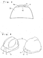
- An embodiment of the safety hat having the front air hole 13 with the horizontal length slightly shorter than the radius of the hat body is shown on the left side, and another embodiment of the safety hat having the short visor portion 12 on the right side.
- the hat body 10 in the present invention can be formed by mold tooling, and in the case it is difficult to form an entire body in one time molding, the body can be separated into a plurality of components for molding.
- a hat body 10 may be as shown in FIG. 5 .
- the inner plate 20 is lined inside the peak portion of the hat body 10.
- the inner plate 20 is, as shown in the flat view above the hat body 10, a thin strip extending in the longitudinal direction of the hat body and provided with a large opening 21 at the center thereof.
- the air passage 25 formed between the peak portion of the hat body 10 and the inner plate 20 in this way and the internal of the hat body 10 are in communication with each other by the opening 21, and the air passage 25 is in communication with the rear air hole 17 at the same time.
- the inner plate 20 has an effect of reinforcing the peak portion of the hat body 10 requiring the strength most, the inner plate 20 is desired to be a small strip as light as possible.
- the shielding mechanism against foreign objects is formed by establishing the weir 22 around the periphery of the opening 21 at the inner plate 20. It is necessary that the opening 21 is positioned closer to the internal surface of the hat body than the periphery thereof, and that the opening 21 is located at a higher position, for instance, by forming bumps on the surface of the inner plate 20.
- a plurality of air vent pores 27, 27 ... penetrating the internal and external surfaces of the hat body 10 at the peak portion thereof.
- the air vent pores 27, 27 ... are, as indicated by the dotted line in the flat view of the inner plate 20, provided at a position opposing to the inner plate 20 and not overlapping the opening 21. Both items are arranged so as not to overlap for the purpose of shielding from foreign objects and protection from water such as rain water, as described above.
- the size of the air vent pores 27, 27 ... is not specifically limited but may be any size capable of retaining sufficient strength of the hat body 10.
- the number of the air vent pores 27, 27 ... is preferably between several and ten or more around the opening 21 opposing to the inner plate 20.
- the undermost air vent pores 27 also functions as a drainage passage.
- the shape of the air vent pores 27, 27 ... is not limited to the circle as shown in the drawing.
- the embodiment shown in FIG. 5 achieves thrilling air permeability by the functions of the front and rear air holes 13, 17 and the air vent pores 27, 27 ....
- the same numerals are applied and the explanations are omitted.
- the embodiment of the hat body 10 shown with reference to the longitudinal side view in FIG. 6 is an example of the modification from the embodiment shown in FIG. 5 , where the visor portion 12 is configured as a part of the inner plate 20 by connecting the front tip of the strip-shaped inner plate 20 to the top end 12a of the visor portion.
- This embodiment allows the air passage 25 to be in direct communication with the air hole 13 in the visor portion 12 so that an even stronger flow of ambient air is formed along the internal wall of the hat body.
- the visor portion 12 is not limited to be defined by the streamlined curvature but may be defined by a flat surface since the ambient air can be brought in smoothly through the air hole 13 in the visor portion 12.
- the number of the opening 21 is not limited to one but there may be a plurality of the opening 21.
- the same numerals are applied and the explanations are omitted.
- a penetration tolerance test (articles 6 and 7) and a shock absorption test (article 8) were performed on all of the described safety hats based on the standard specified by Minister of Labor (Announcement No. 39 by Ministry of Labor, June 5 th , 1991), and the performance specified by each article was confirmed.
- the safety hat according to the present invention may be used for various works such as construction, civil engineering, operation of heavy equipment, steering a working vehicle, a marine vessel and an aircraft, duties of security, police and fire-fighting inside and outside a building.
- the safety hat may also be widely used in a construction site of a building or a dam, a work site of a road or a tunnel, a dockyard, an ironworks, an iron factory, a quarry, and other various work sites and factories.
Landscapes
- Helmets And Other Head Coverings (AREA)
Description
- The present invention relates to a structure of a safety hat worn for protection of one's head during various works including construction and civil engineering.
- In sites and factories of various works, an worker avoids dangers from a flying object or a falling object as well as danger of falling by wearing a safety hat before such a danger happens, but the safety hat steams the worker' s head with sweat by wearing the safety hat for a long time during summer time or hard work with a large quantity of labor. The steamed condition not only makes the works painful but also lowers the working efficiency.
- As an attempt to provide the safety hat with air permeability, there has been known a safety hat formed by mesh or mesh porous materials so that absent areas are alternately positioned (see
JP 60-143736U JP 58-7832U JP 1-94430U
Although there has been disclosed a helmet having air permeability and protection from rain at the same time (seeJP 42-20108U - Inventors of the present invention have suggested a safety hat including a double-structured hat body as a safety hat with air permeability and protection from rain (see
WO 95/28101 WO 98/23176 JP 2000-303246 -
JP 2001-003220 - The present invention is intended for providing a safety hat with overwhelming light weight and marvelous air permeability as well as measures for water protection against rainy weather and the like.
- The safety hat according to the present invention includes the features of claim 1.
- Preferred optional features are recited in the dependent claims.
- The safety hat according to the present invention achieves overwhelming light-weight and marvelous air permeability as well as measures for water protection against rainy weather and the like by introducing a large amount of ambient air into the hat body along the visor portion defined by a streamlined curvature.
In addition to the effects described above, the other safety hat with the inner plate lined inside the peak portion of the hat body facilitates the molding process thereof. Further, air permeability can be also dramatically improved by providing the air vent pores at the peak portion of the hat body. -
-
FIG. 1 is; a perspective view showing the hat body from the diagonally upper front. -
FIG. 2 is; a longitudinal side view showing the center portion of the hat body. -
FIG. 3 is; a rear view of the hat body. -
FIG. 4 is; a perspective view showing an example of the modified hat body. -
FIG. 5 indicates; a longitudinal side view showing another example of the modified hat body and a flat view of the inner plate. -
FIG. 6 indicates; a longitudinal side view showing another example of the modified hat body and a flat view of the inner plate. -
- 10.
- Hat body
- 12.
- Visor portion
- 12a.
- Top end of the visor portion
- 13, 17.
- Air hole
- 15, 19.
- Eave portion
- 18.
- Back portion of the head
- 18a.
- Top end of the back portion of the head
- 20.
- Inner plate
- 21.
- Opening
- 22.
- Weir
- 25.
- Air passage
- 27.
- Air vent pore
- The most preferred embodiment of the safety hat according to the present invention is described below with reference to the drawings.
FIG. 1 is a perspective view of thehat body 10 forming the main body of the safety hat as viewed from the upper front thereof, which is generally provided therein with a shock-absorbing liner for absorbing shock applied to thehat body 10, a wearing body (configured with a hammock, a head band, a loop and the like) for retaining the safety hat on the workers head and making it easy to wear the safety hat, and a chin strap for preventing the safety hat from dropping.
Thehat body 10 may be made of synthetic resin such as polyester, polypropylene, polyethylene, polycarbonate, and ABS resin. When strength is required, the hat body may also be made of iron, steel, aluminum, aluminum base alloy, and other high-strength alloys, and fiber-reinforced plastic and ceramic may be also used depending on the application of the safety hat. - The
visor portion 12 in front of thehat body 10 is provided with thefront air hole 13 in the horizontal direction. The horizontal length of thefront air hole 13 is preferably equivalent to or larger than the radius of thehat body 10. The number of thefront air hole 13 is not necessarily one, but when there are more than one, the total length of the plurality of thefront air hole 13 is preferably equivalent to or larger than the radius of thehat body 10. The upper limit of the horizontal length should be approximately the diameter of thehat body 10. Thevisor portion 12 is defined by the streamlined curvature so that the ambient air can be brought in smoothly, and theeave portion 15 of thehat body 10 covers thetop end 12a of thevisor portion 12 from the outside without contacting the same to form thefront air hole 13. -
FIG. 2 is a longitudinal side view showing the center portion of thehat body 10, where thetop end 12a of thevisor portion 12 and the lower end of thefront eave portion 15 play the role of a shielding mechanism against annealing wire and any other falling objects and flying objects that may enter thehat body 10 from outside since thetop end 12a of thevisor portion 12 and the lower end of thefront eave portion 15 are overlapped in the horizontal direction. In order to have high air permeability, the distance between thetop end 12a of thevisor portion 12 and the lower end of thefront eave portion 15 should preferably be long as much as possible on the condition that the shielding effect against foreign objects and weathering structure are satisfied. - The
air hole 17 is also provided at the opposing position to thevisor portion 12 of thehat body 10, which is located at the back of the peak portion of thehat body 10 in this embodiment. Therear air hole 17 is preferably located at a position opposing to thevisor portion 12, especially at the back of the peak portion of thehat body 10, since therear air hole 17 is required to function as an outlet for the air introduced into and staying inside thehat body 10 while thefront air hole 13 mainly functions as an inlet for the ambient air. - In this embodiment, the
rear air hole 17 is also formed by the back portion of thehead 18 of thehat body 10 defined by the streamlined curvature and therear eave portion 19 of thehat body 10 covering thetop end 18a of the back of the head from the outside without contacting the same, like thefront air hole 13, resulting to have the shielding mechanism against foreign objects and weathering structure. The safety hat according to the present invention is not limited to have this configuration as long as therear air hole 17 is equipped with the shielding mechanism against foreign objects and weathering structure. -
FIG. 3 is a rear view of thehat body 10 showing therear air hole 17 as described above.
According to the present invention, since thefront air hole 13 and therear air hole 17 are open to the ambient air, the ambient air flows through thehat body 10. Especially, since a large amount of ambient air introduced into the hat body along thevisor portion 12 defined by the streamlined curvature is directed to therear air hole 17 along the internal wall of the hat body to flow without dispersion, wet air tending to stay in thehat body 10 consequently follows the flow of the ambient air to be discharged out of the hat body in an instant. The structure of the safety hat according to the present invention allows a large amount of ambient air flowing from thefront air hole 13 to directly contact the forehead which is the most sensitive part to cold air on the head of the wearer of the safety hat, and therefore achieves an excellent cooling effect in somesthetic terms. -
FIG. 4 is a perspective view showing an example of the modified hat body. An embodiment of the safety hat having thefront air hole 13 with the horizontal length slightly shorter than the radius of the hat body is shown on the left side, and another embodiment of the safety hat having theshort visor portion 12 on the right side. - The
hat body 10 in the present invention can be formed by mold tooling, and in the case it is difficult to form an entire body in one time molding, the body can be separated into a plurality of components for molding. For instance, if it is difficult to form therear air hole 17 at a time, ahat body 10 may be as shown inFIG. 5 .
According to the embodiment of thehat body 10 shown in the longitudinal side view inFIG. 5 , theinner plate 20 is lined inside the peak portion of thehat body 10. Theinner plate 20 is, as shown in the flat view above thehat body 10, a thin strip extending in the longitudinal direction of the hat body and provided with alarge opening 21 at the center thereof. Theair passage 25 formed between the peak portion of thehat body 10 and theinner plate 20 in this way and the internal of thehat body 10 are in communication with each other by theopening 21, and theair passage 25 is in communication with therear air hole 17 at the same time. - While the
inner plate 20 has an effect of reinforcing the peak portion of thehat body 10 requiring the strength most, theinner plate 20 is desired to be a small strip as light as possible.
As described above, it is important for therear air hole 17 to have the shielding mechanism against the foreign object and a weathering structure. With this embodiment, the shielding mechanism against foreign objects is formed by establishing theweir 22 around the periphery of theopening 21 at theinner plate 20. It is necessary that theopening 21 is positioned closer to the internal surface of the hat body than the periphery thereof, and that theopening 21 is located at a higher position, for instance, by forming bumps on the surface of theinner plate 20. - With this embodiment, in order to improve air permeability, there are provided a plurality of air vent pores 27, 27 ... penetrating the internal and external surfaces of the
hat body 10 at the peak portion thereof. The air vent pores 27, 27 ... are, as indicated by the dotted line in the flat view of theinner plate 20, provided at a position opposing to theinner plate 20 and not overlapping theopening 21. Both items are arranged so as not to overlap for the purpose of shielding from foreign objects and protection from water such as rain water, as described above. - The size of the air vent pores 27, 27 ... is not specifically limited but may be any size capable of retaining sufficient strength of the
hat body 10. The number of the air vent pores 27, 27 ... is preferably between several and ten or more around theopening 21 opposing to theinner plate 20. The undermost air vent pores 27 also functions as a drainage passage. The shape of the air vent pores 27, 27 ... is not limited to the circle as shown in the drawing.
The embodiment shown inFIG. 5 achieves marvelous air permeability by the functions of the front and rear air holes 13, 17 and the air vent pores 27, 27 .... For the materials identical to the materials in the embodiment shown with reference toFIGS. 1 to 3 , the same numerals are applied and the explanations are omitted. - The embodiment of the
hat body 10 shown with reference to the longitudinal side view inFIG. 6 is an example of the modification from the embodiment shown inFIG. 5 , where thevisor portion 12 is configured as a part of theinner plate 20 by connecting the front tip of the strip-shapedinner plate 20 to thetop end 12a of the visor portion. This embodiment allows theair passage 25 to be in direct communication with theair hole 13 in thevisor portion 12 so that an even stronger flow of ambient air is formed along the internal wall of the hat body. With this embodiment, thevisor portion 12 is not limited to be defined by the streamlined curvature but may be defined by a flat surface since the ambient air can be brought in smoothly through theair hole 13 in thevisor portion 12. - With this embodiment, rain water entered from the
air passage 25 is discharged from the air holes 13, 17. The number of theopening 21 is not limited to one but there may be a plurality of theopening 21. For the materials shown inFIG. 6 identical to the materials in the embodiment shown with reference toFIG. 5 , the same numerals are applied and the explanations are omitted. - A penetration tolerance test (articles 6 and 7) and a shock absorption test (article 8) were performed on all of the described safety hats based on the standard specified by Minister of Labor (Announcement No. 39 by Ministry of Labor, June 5th, 1991), and the performance specified by each article was confirmed.
- The safety hat according to the present invention may be used for various works such as construction, civil engineering, operation of heavy equipment, steering a working vehicle, a marine vessel and an aircraft, duties of security, police and fire-fighting inside and outside a building. The safety hat may also be widely used in a construction site of a building or a dam, a work site of a road or a tunnel, a dockyard, an ironworks, an iron factory, a quarry, and other various work sites and factories.
Claims (8)
- A safety hat comprising a hat body (10) and a visor portion (12) in front of the hat body (10),
wherein a front eave portion (15) of the hat body (10) covers a top end (12a) of the visor portion (12) from the outside without contacting the same, so as to form a front air hole (13), and
wherein a rear eave portion (19) of the hat body (10) covers a top end (18a) of a rear portion (18) of the hat body (10) without contacting the same, so as to form a rear air hole (17),
characterized in that
the visor portion (12) as well as an internal wall of the hat body (10) are defined by a streamlined curvature so that air can smoothly flow into the safety hat through the front air hole (13), along the internal wall of the hat body (10) and out of the rear air hole (17) without dispersion, and
the top end (12a) of the visor portion (12) is located vertically above the lower end of the front eave portion (15). - The safety hat according to claim 1, wherein a shielding mechanism against foreign objects and a weathering structure is disposed at the front air hole (13) and/or the rear air hole (17).
- The safety hat according to claim 1 or 2, wherein the rear air hole (17) is located at a position opposite to the visor portion (12) at the back of the hat body (10).
- The safety hat according to any one of claims 1 to 3, wherein the front air hole (13) is in the horizontal direction.
- The safety hat according to any one of claims 1 to 4, wherein an inner plate (20) with an opening (21) at the center is lined at a peak portion of the hat body (10), and an air passage (25) formed between the peak portion and the inner plate (20) is in communication with the rear air hole (17).
- The safety hat according to claim 5, wherein a front end of the inner plate (20) is connected to the top end (12a) of the visor portion (12), and the air passage (25) is in communication with the front air hole (13).
- The safety hat according to claim 5 or 6, wherein the opening (21) of the inner plate (20) is located closer to an inside of the hat body (10) than to a periphery thereof, and a plurality of vent pores (27) opposite to the inner plate (20) at the peak portion of the hat body (10) and penetrating internal and external surfaces of the hat body (10) are disposed at positions not overlapping the opening (21).
- The safety hat according to any one of claims 5 to 7, wherein the inner plate (20) has a weir (22) established at a periphery of its opening (21).
Applications Claiming Priority (2)
| Application Number | Priority Date | Filing Date | Title |
|---|---|---|---|
| JP2003276380 | 2003-07-18 | ||
| PCT/JP2004/010013 WO2005006901A1 (en) | 2003-07-18 | 2004-07-14 | Protective cap |
Publications (3)
| Publication Number | Publication Date |
|---|---|
| EP1649770A1 EP1649770A1 (en) | 2006-04-26 |
| EP1649770A4 EP1649770A4 (en) | 2007-08-22 |
| EP1649770B1 true EP1649770B1 (en) | 2010-04-07 |
Family
ID=34074588
Family Applications (1)
| Application Number | Title | Priority Date | Filing Date |
|---|---|---|---|
| EP04747479A Expired - Lifetime EP1649770B1 (en) | 2003-07-18 | 2004-07-14 | Protective cap |
Country Status (7)
| Country | Link |
|---|---|
| US (1) | US7818821B2 (en) |
| EP (1) | EP1649770B1 (en) |
| JP (1) | JPWO2005006901A1 (en) |
| AU (1) | AU2004257507A1 (en) |
| CA (1) | CA2532561A1 (en) |
| DE (1) | DE602004026449D1 (en) |
| WO (1) | WO2005006901A1 (en) |
Families Citing this family (6)
| Publication number | Priority date | Publication date | Assignee | Title |
|---|---|---|---|---|
| WO2008079525A2 (en) * | 2006-11-03 | 2008-07-03 | Lineweight Llc | Vented ballistic combat helmet |
| JP2014159661A (en) * | 2013-02-20 | 2014-09-04 | Birumateru Kk | Cap with louver |
| US9420839B2 (en) * | 2012-10-19 | 2016-08-23 | Builmatel Co., Ltd. | Air permeable headwear |
| US20150020292A1 (en) * | 2013-07-16 | 2015-01-22 | Juan I Diaz | Headgear having insulated ventilation channels and perspiration and moisture drainage channel |
| JP7017532B2 (en) * | 2019-02-22 | 2022-02-08 | 株式会社Shoei | Airflow control member for helmet and helmet |
| US12532932B1 (en) * | 2025-06-25 | 2026-01-27 | Juan Jimenez | Headwear with airflow circulation and cooling effect |
Family Cites Families (20)
| Publication number | Priority date | Publication date | Assignee | Title |
|---|---|---|---|---|
| US3039108A (en) * | 1958-07-14 | 1962-06-19 | John W Lohrenz | Protective helmet |
| US3457563A (en) * | 1967-10-12 | 1969-07-29 | Wolverine World Wide Inc | Safety headgear construction |
| US4141085A (en) * | 1977-09-22 | 1979-02-27 | Adams Sr John | Vented helmet and face shield |
| US4369782A (en) * | 1981-05-15 | 1983-01-25 | Mcgee Terrill | Eyewashing apparatus |
| JPS59113325U (en) | 1983-01-20 | 1984-07-31 | 本田技研工業株式会社 | helmet |
| US4550445A (en) * | 1984-05-04 | 1985-11-05 | Fender David A | Ventilated athletic cap |
| DE8426051U1 (en) * | 1984-09-04 | 1985-01-31 | Hauptverband der gewerblichen Berufsgenossenschaften e.V., 5300 Bonn | Naturally ventilated safety helmet |
| IT1177288B (en) * | 1984-11-22 | 1987-08-26 | Pier Luigi Nava | FULL HELMET |
| JPS63175125U (en) | 1986-06-13 | 1988-11-14 | ||
| JPS6389924U (en) * | 1986-11-27 | 1988-06-10 | ||
| JPH0516182Y2 (en) | 1988-10-31 | 1993-04-28 | ||
| US5090054A (en) * | 1989-05-26 | 1992-02-25 | Grilliot William L | Ventilated hood for firefighter |
| US5829065A (en) * | 1994-02-15 | 1998-11-03 | Cahill; Kevin J. | Industrial protective helmet |
| US5771497A (en) * | 1995-06-09 | 1998-06-30 | Hoodco 446 Limited | Article of headwear |
| GB2307842A (en) * | 1995-12-05 | 1997-06-11 | Lin Chan Yen | Ventilated protective helmet |
| JPH10195708A (en) * | 1996-12-30 | 1998-07-28 | T S Tec Kk | Helmet with ventilator |
| JPH10331021A (en) | 1997-05-30 | 1998-12-15 | Tokyo Seat Kk | Helmet |
| US5996128A (en) * | 1998-12-31 | 1999-12-07 | Korea Ogk Co., Ltd. | Air flow adjusting rear member of the helmet |
| US6061834A (en) * | 1999-06-14 | 2000-05-16 | Liao; Cheng-An | Air ventilation safety helmet |
| JP2001003220A (en) * | 1999-06-24 | 2001-01-09 | Tanizawa Seisakusho Ltd | Helmet |
-
2004
- 2004-07-14 JP JP2005511828A patent/JPWO2005006901A1/en active Pending
- 2004-07-14 EP EP04747479A patent/EP1649770B1/en not_active Expired - Lifetime
- 2004-07-14 US US10/565,070 patent/US7818821B2/en not_active Expired - Fee Related
- 2004-07-14 CA CA002532561A patent/CA2532561A1/en not_active Abandoned
- 2004-07-14 DE DE602004026449T patent/DE602004026449D1/en not_active Expired - Lifetime
- 2004-07-14 WO PCT/JP2004/010013 patent/WO2005006901A1/en not_active Ceased
- 2004-07-14 AU AU2004257507A patent/AU2004257507A1/en not_active Abandoned
Also Published As
| Publication number | Publication date |
|---|---|
| AU2004257507A1 (en) | 2005-01-27 |
| US7818821B2 (en) | 2010-10-26 |
| CA2532561A1 (en) | 2005-01-27 |
| WO2005006901A1 (en) | 2005-01-27 |
| JPWO2005006901A1 (en) | 2007-04-12 |
| EP1649770A1 (en) | 2006-04-26 |
| EP1649770A4 (en) | 2007-08-22 |
| DE602004026449D1 (en) | 2010-05-20 |
| US20060230506A1 (en) | 2006-10-19 |
Similar Documents
| Publication | Publication Date | Title |
|---|---|---|
| EP0890320B1 (en) | Protective cap | |
| JPWO1997006706A1 (en) | hard hat | |
| US4334325A (en) | Garment hood | |
| KR100602508B1 (en) | Full-face type helmet | |
| US7818821B2 (en) | Protective cap | |
| US6151718A (en) | Safety cap | |
| JPWO1998023176A1 (en) | hard hat | |
| WO1995028101A1 (en) | Safety cap | |
| CN210276073U (en) | Multifunctional safety helmet for electric power engineering construction | |
| JP2001003220A (en) | Helmet | |
| CN221511080U (en) | Communication helmet | |
| CN214386288U (en) | A safety helmet for tunnel | |
| KR200254319Y1 (en) | A Safety Cap | |
| KR200187556Y1 (en) | Ventilative safety helmet | |
| JPH08209431A (en) | Protective cap | |
| CN219939819U (en) | Intelligent safety helmet | |
| JP2000303246A (en) | Protective hat | |
| CN223695038U (en) | Ventilated and rainwater-pouring-invasion-preventing safety helmet | |
| JP2007084943A (en) | Safety helmet | |
| KR102469613B1 (en) | Functional safety helmet with ventilation flow path | |
| CN212814634U (en) | Safety construction cap structure for maintenance of construction machinery | |
| KR101239221B1 (en) | Multi-functional helmet | |
| KR200398751Y1 (en) | safety hat | |
| KR20010075831A (en) | Ventilative safety helmet | |
| KR200152879Y1 (en) | Hard hat |
Legal Events
| Date | Code | Title | Description |
|---|---|---|---|
| PUAI | Public reference made under article 153(3) epc to a published international application that has entered the european phase |
Free format text: ORIGINAL CODE: 0009012 |
|
| 17P | Request for examination filed |
Effective date: 20060208 |
|
| AK | Designated contracting states |
Kind code of ref document: A1 Designated state(s): DE FR GB IT |
|
| DAX | Request for extension of the european patent (deleted) | ||
| RBV | Designated contracting states (corrected) |
Designated state(s): DE FR GB IT |
|
| A4 | Supplementary search report drawn up and despatched |
Effective date: 20070719 |
|
| 17Q | First examination report despatched |
Effective date: 20080606 |
|
| GRAP | Despatch of communication of intention to grant a patent |
Free format text: ORIGINAL CODE: EPIDOSNIGR1 |
|
| GRAS | Grant fee paid |
Free format text: ORIGINAL CODE: EPIDOSNIGR3 |
|
| GRAA | (expected) grant |
Free format text: ORIGINAL CODE: 0009210 |
|
| AK | Designated contracting states |
Kind code of ref document: B1 Designated state(s): DE FR GB IT |
|
| REG | Reference to a national code |
Ref country code: GB Ref legal event code: FG4D |
|
| REF | Corresponds to: |
Ref document number: 602004026449 Country of ref document: DE Date of ref document: 20100520 Kind code of ref document: P |
|
| PLBE | No opposition filed within time limit |
Free format text: ORIGINAL CODE: 0009261 |
|
| STAA | Information on the status of an ep patent application or granted ep patent |
Free format text: STATUS: NO OPPOSITION FILED WITHIN TIME LIMIT |
|
| 26N | No opposition filed |
Effective date: 20110110 |
|
| GBPC | Gb: european patent ceased through non-payment of renewal fee |
Effective date: 20100714 |
|
| PG25 | Lapsed in a contracting state [announced via postgrant information from national office to epo] |
Ref country code: IT Free format text: LAPSE BECAUSE OF FAILURE TO SUBMIT A TRANSLATION OF THE DESCRIPTION OR TO PAY THE FEE WITHIN THE PRESCRIBED TIME-LIMIT Effective date: 20100407 |
|
| REG | Reference to a national code |
Ref country code: FR Ref legal event code: ST Effective date: 20110331 |
|
| PG25 | Lapsed in a contracting state [announced via postgrant information from national office to epo] |
Ref country code: FR Free format text: LAPSE BECAUSE OF NON-PAYMENT OF DUE FEES Effective date: 20100802 |
|
| PG25 | Lapsed in a contracting state [announced via postgrant information from national office to epo] |
Ref country code: GB Free format text: LAPSE BECAUSE OF NON-PAYMENT OF DUE FEES Effective date: 20100714 |
|
| PGFP | Annual fee paid to national office [announced via postgrant information from national office to epo] |
Ref country code: DE Payment date: 20180727 Year of fee payment: 15 |
|
| REG | Reference to a national code |
Ref country code: DE Ref legal event code: R119 Ref document number: 602004026449 Country of ref document: DE |
|
| PG25 | Lapsed in a contracting state [announced via postgrant information from national office to epo] |
Ref country code: DE Free format text: LAPSE BECAUSE OF NON-PAYMENT OF DUE FEES Effective date: 20200201 |