EP1649533B1 - A sealing structure forpolymer electrolyte fuel cell - Google Patents
A sealing structure forpolymer electrolyte fuel cell Download PDFInfo
- Publication number
- EP1649533B1 EP1649533B1 EP03817081A EP03817081A EP1649533B1 EP 1649533 B1 EP1649533 B1 EP 1649533B1 EP 03817081 A EP03817081 A EP 03817081A EP 03817081 A EP03817081 A EP 03817081A EP 1649533 B1 EP1649533 B1 EP 1649533B1
- Authority
- EP
- European Patent Office
- Prior art keywords
- fuel cell
- electrolyte fuel
- rubber
- polymer electrolyte
- sealing
- Prior art date
- Legal status (The legal status is an assumption and is not a legal conclusion. Google has not performed a legal analysis and makes no representation as to the accuracy of the status listed.)
- Expired - Lifetime
Links
Images




Classifications
-
- H—ELECTRICITY
- H01—ELECTRIC ELEMENTS
- H01M—PROCESSES OR MEANS, e.g. BATTERIES, FOR THE DIRECT CONVERSION OF CHEMICAL ENERGY INTO ELECTRICAL ENERGY
- H01M8/00—Fuel cells; Manufacture thereof
- H01M8/02—Details
- H01M8/0271—Sealing or supporting means around electrodes, matrices or membranes
- H01M8/028—Sealing means characterised by their material
- H01M8/0284—Organic resins; Organic polymers
-
- H—ELECTRICITY
- H01—ELECTRIC ELEMENTS
- H01M—PROCESSES OR MEANS, e.g. BATTERIES, FOR THE DIRECT CONVERSION OF CHEMICAL ENERGY INTO ELECTRICAL ENERGY
- H01M8/00—Fuel cells; Manufacture thereof
- H01M8/02—Details
-
- H—ELECTRICITY
- H01—ELECTRIC ELEMENTS
- H01M—PROCESSES OR MEANS, e.g. BATTERIES, FOR THE DIRECT CONVERSION OF CHEMICAL ENERGY INTO ELECTRICAL ENERGY
- H01M8/00—Fuel cells; Manufacture thereof
- H01M8/02—Details
- H01M8/0202—Collectors; Separators, e.g. bipolar separators; Interconnectors
- H01M8/0204—Non-porous and characterised by the material
- H01M8/0221—Organic resins; Organic polymers
-
- H—ELECTRICITY
- H01—ELECTRIC ELEMENTS
- H01M—PROCESSES OR MEANS, e.g. BATTERIES, FOR THE DIRECT CONVERSION OF CHEMICAL ENERGY INTO ELECTRICAL ENERGY
- H01M8/00—Fuel cells; Manufacture thereof
- H01M8/02—Details
- H01M8/0271—Sealing or supporting means around electrodes, matrices or membranes
- H01M8/028—Sealing means characterised by their material
- H01M8/0282—Inorganic material
-
- H—ELECTRICITY
- H01—ELECTRIC ELEMENTS
- H01M—PROCESSES OR MEANS, e.g. BATTERIES, FOR THE DIRECT CONVERSION OF CHEMICAL ENERGY INTO ELECTRICAL ENERGY
- H01M8/00—Fuel cells; Manufacture thereof
- H01M8/24—Grouping of fuel cells, e.g. stacking of fuel cells
-
- H—ELECTRICITY
- H01—ELECTRIC ELEMENTS
- H01M—PROCESSES OR MEANS, e.g. BATTERIES, FOR THE DIRECT CONVERSION OF CHEMICAL ENERGY INTO ELECTRICAL ENERGY
- H01M8/00—Fuel cells; Manufacture thereof
- H01M8/02—Details
- H01M8/0202—Collectors; Separators, e.g. bipolar separators; Interconnectors
- H01M8/0258—Collectors; Separators, e.g. bipolar separators; Interconnectors characterised by the configuration of channels, e.g. by the flow field of the reactant or coolant
- H01M8/0263—Collectors; Separators, e.g. bipolar separators; Interconnectors characterised by the configuration of channels, e.g. by the flow field of the reactant or coolant having meandering or serpentine paths
-
- H—ELECTRICITY
- H01—ELECTRIC ELEMENTS
- H01M—PROCESSES OR MEANS, e.g. BATTERIES, FOR THE DIRECT CONVERSION OF CHEMICAL ENERGY INTO ELECTRICAL ENERGY
- H01M8/00—Fuel cells; Manufacture thereof
- H01M8/02—Details
- H01M8/0271—Sealing or supporting means around electrodes, matrices or membranes
- H01M8/0273—Sealing or supporting means around electrodes, matrices or membranes with sealing or supporting means in the form of a frame
-
- Y—GENERAL TAGGING OF NEW TECHNOLOGICAL DEVELOPMENTS; GENERAL TAGGING OF CROSS-SECTIONAL TECHNOLOGIES SPANNING OVER SEVERAL SECTIONS OF THE IPC; TECHNICAL SUBJECTS COVERED BY FORMER USPC CROSS-REFERENCE ART COLLECTIONS [XRACs] AND DIGESTS
- Y02—TECHNOLOGIES OR APPLICATIONS FOR MITIGATION OR ADAPTATION AGAINST CLIMATE CHANGE
- Y02E—REDUCTION OF GREENHOUSE GAS [GHG] EMISSIONS, RELATED TO ENERGY GENERATION, TRANSMISSION OR DISTRIBUTION
- Y02E60/00—Enabling technologies; Technologies with a potential or indirect contribution to GHG emissions mitigation
- Y02E60/30—Hydrogen technology
- Y02E60/50—Fuel cells
Definitions
- the present invention relates to a sealing structure for polymer electrolyte fuel cell, and more particularly to the sealing structure for polymer electrolyte fuel cell to prevent reaction gas or coolant etc. from leaking through the commissure between a bipolar plate and a membrane electrode assembly.
- a polymer electrolyte fuel cell generates electricity and heat by electrochemically reacting a fuel gas containing hydrogen and an oxidizer gas containing oxygen.
- the polymer electrolyte fuel cell is capable of working at a low temperature of 70-80 °C and of maintaining great current density.
- the polymer electrolyte fuel cell has fast startup performance, can be miniaturized, and can be made into light weight cells, thus suitable for use in such applications as portable power source, power source for vehicles, residential equipments of steam supply and power generation, etc.
- Fig. 1 illustrates an embodiment of the polymer electrolyte fuel cell, which comprises a membrane electrode assembly(MEA, 10) comprising a polymer electrolyte membrane and an electrode, a gas diffusion layer(fluid distribution layer, 12) delivering the gas used in a reaction to the electrode and discharging the reaction products, a conductive bipolar plate(separator, 14) supplying a reaction gas and a coolant from outside and separating oxidized electrode(anode) from deoxidized electrode(cathode), and the like.
- a fuel cell is composed by stacking these membrane electrode assembly, gas diffusion layer and bipolar plate as many as necessary, and the stack forms a single body with an appropriate pressure given from outside by a equipment, so each unit cell is not out of line or slipped.
- a number of manifolds(20) are formed in the upper part and the lower part of the membrane electrode assembly(10) and the bipolar plate(14) for supplying or discharging hydrogen, oxygen needed in a reaction, and coolant needed to cool the reaction heat. And hydrogen, oxygen and coolant supplied from outside are taken into the electrode passing through a pipe outside the stack, the manifold of the bipolar plate, and a gas-flow path formed on the bipolar plate of each unit cell.
- a sealing means should be included to prevent hydrogen, oxygen and coolant from leaking from each manifold and the reaction site where hydrogen and oxygen react.
- a sealing structure for the fuel cell must exert sealing performance in the case of frequent expansion and contraction, and only if the stress distribution arising in each element of fuel cell in expansion and contraction is as uniform as possible, the fatigue failure can be prevented.
- a gasket is disposed around the electrode and manifold.
- silicon sheet or Teflon sheet strengthened by glass fibers is often used because of its easy manufacturing advantage and little thickness deviation.
- This strengthened silicon sheet or Teflon sheet has an excellent mechanical strength supported by internal glass fibers, so it can exert mechanical toughness under the excessive pressure in the time when a stack is bound. But the rate of contraction and restoration are not so high that, when the fuel cell operates, gas is apprehended to leak for the expansion of parts by heat and water. Moreover gas can leak through the surface of the gasket because the surface is rough and the material is relatively hard.
- Another defect is that, if formed thicker than a gas diffusion layer when a stack is bound, the resistance increases because the mechanical strength is greater than that of a carbon paper or a carbon cloth generally used as a gas diffusion layer, and the contact between a gas diffusion layer and a bipolar plate is not tight. On the contrary, there is a problem that, if formed too thin, gas leaks because the pressure on the surface of the gasket is not enough. Therefore it is difficult to determine the proper thickness.
- Another way for sealing the fuel cell is to use rubber with superior elastic restitution force and soft property containing silicon, fluorine or olefin as a material of a gasket.
- rubber with superior elastic restitution force and soft property containing silicon, fluorine or olefin as a material of a gasket.
- the way of manufacturing a gasket in the shape of O-ring using a metal mold has the defect that, after manufacturing a gasket, it must be placed on the surface of a bipolar plate one by one when a stack is bound. And the way of jet molding with a metal mold being placed directly on a bipolar plate has the defect that, in the time of manufacturing a gasket, the shape and the dimension of a metal mold must be same with the gasket.
- the conventional way of manufacturing a gasket using a dispenser is the way of putting sealant in an injector and the like and pressing it, so has the problem that the height of rubber at starting point and ending point cannot be set uniformly. That is, the liquid state of rubber material is filled along a route of a sealing groove using a dispenser operated by X-Y axis robot, after forming the sealing groove in advance on a bipolar plate, with a width and a depth. The rubber overlaps in ending point with that of starting point, so height become greater than that of other part.
- US6,261,711 discloses a fluid seal for a fuel cell that includes a compressible member on a first fluid flow plate and a gasket disposed within a groove on a second fluid flow plate.
- WO 03/007408 discloses a method of coating with a liquid seal material.
- the method comprises moving a nozzle section installed in a seal material coating device to be nearer the separator than other portions than the coating start portion, and moving the nozzle section at a lower horizontal movement speed than that of the other portions than the coating start portion in a seal material coating start portion.
- the present invention was invented to overcome the defects of conventional technologies, and it is an object of the present invention to provide a sealing structure for polymer electrolyte fuel cell whose structure not only does not lower the sealing performance although the thickness deviation of a gasket occurs, but also can disperse nonuniform stress distribution onto a bipolar plate and a membrane electrode assembly.
- the thickness deviation in a gasket can be softened by interposing a gasket between a rubber and a membrane electrode assembly after filling rubber in a sealing groove formed on a bipolar plate using a dispenser. Also, nonuniform stress distribution can be resolved because a gasket covers with a pressure despite the height deviation of rubber, and a stress is not directly transmitted to a membrane electrode assembly and dispersed by a gasket despite nonuniform stress distribution.
- sealing groove is formed in the perimeter of the reaction site of bipolar plate, and the perimeter of the manifold of hydrogen, oxygen and coolant as well.
- the height of starting point and ending point can be uniform.
- the width of the anchor is wide enough, although the height increases temporarily by the partial overlapping of starting point with ending point, the height becomes uniform by the diffusing of rubber right and left.
- the anchor has a width of 1.5 times of the width of the sealing groove. Therefore, damaging the sealing performance, with the rubber being diffused excessively and thinner than that of sealing groove, can be prevented effectively.
- the sealing groove and the anchor have same depth, for a dispenser to move at uniform speed. Because, in the case that the depth of an anchor is different from the depth of sealing groove, the nonuniform moving speed of a dispenser can be brought about to fill up to the surface of groove.
- an anchor can be located anywhere only if it is contacted with the sealing groove. That is, by expanding the partial width of sealing groove right and left, an anchor can be formed. But, it is more desirable that the anchor is formed vertically to a route direction of the sealing groove in the periphery of the sealing groove.
- the height of rubber filled in an anchor portion is greater than the height of rubber filled in a sealing groove portion, and when the bipolar plate is bound to a fuel cell stack relatively more force is given to the perimeter of a bipolar plate than inner part. Therefore, by forming an anchor in the periphery of sealing site, the pressure given to the perimeter can be absorbed effectively, and consequently the pressure given to the entire bipolar plate can be distributed uniformly. In this respect, it is more desirable that the anchors on each of the bipolar plate located in the front and the rear of said membrane electrode assembly, are located symmetrically to each other when a fuel cell bound to a stack.
- the rubber is made of any of rubber materials containing silicon, fluorine or olefin.
- the gasket is manufactured of the same material with the bipolar plate by this the deformation and nonuniform stress distribution caused by the difference of heat expansion rate can be prevented.
- the present invention includes a polymer electrolyte fuel cell comprising the sealing structure above-mentioned.
- a reaction site 102 where hydrogen reacts with oxygen is formed, in the upper part manifold 104, 106, 108 are formed where each of hydrogen, oxygen and coolant is supplied. Also, in the lower part manifold 104', 106', 108' to discharge each of coolant, oxygen and hydrogen are formed.
- the Bipolar plate 100 plays the role that hydrogen and oxygen do not mixed in a fuel cell, and that membrane electrode assembly is connected electrically, and functions as mechanical supporter of stacked unit cells. Also it functions that reaction gas flows to electrode evenly, membrane is not dry through adequate water management, and water created in deoxidation electrode is discharged.
- As the material of bipolar plate 100 graphite or carbon composite can be used, and also metallic plate is used. In the case of metallic plate is used, it can be eroded so it is necessary to coat the surface with high-conductive, anticorrosive material. In this embodiment carbon composite is used as bipolar plate 100.
- sealing grooves 110, 110' are formed, in Fig. 2 and Fig. 3 the sealing grooves filled with rubber are illustrated.
- the anchor 112 which has the width of 1.5 times of the width of the sealing groove 110 is formed to be extended toward the outside of bipolar plate 100.
- the sealing groove and the anchor can be formed by CNC processing or press metallic pattern etc., the sealing groove 110 is formed to have the depth of 0.3mm and the width of 2mm in the illustrated embodiment, and the anchor 112 is formed to have the depth of 0.3mm and the width of 3mm.
- rubber is discharged from a dispenser(not illustrated) with the width of 1.2mm and the height of 0.60mm. That is, rubber is filled in a sealing groove in the state of partially projected from the surface of bipolar plate, and the definite dimension of a sealing groove and an anchor is changeable according to the required capacity and the size of fuel cell.
- ordinary membrane electrode assembly 300 is located in the center of a fuel cell using above bipolar plate 100, a couple of gasket 200, 200' are in contact with the front and rear side of membrane electrode assembly 300, bored in the portion of 202, 204, 206, 208, 206', 208' each corresponding to the reaction site 102, hydrogen, oxygen and coolant manifold 104, 106, 108, 104', 106', 108', and a couple of the bipolar plate 100, 100' are adhered to the outside.
- a couple of gas diffusion layer 310, 310' are adhered to the central front and rear side of the membrane electrode assembly 300, and the edge of the portion 202 of the gasket 200 corresponding to reaction site is adhered to, in contact, the side of the gas diffusion layer 310, so membrane electrode assembly 300 function as structural supporter to uniform the entire thickness.
- Above hydrogen, oxygen and coolant manifold 304, 306, 308 are formed in the upper and lower part of membrane electrode assembly 300.
- sealing performance is highly improved because a rubber and a gasket seal doubly, but also in the case the surface of rubber or gasket is nonuniform it is buffered and supplemented by the interaction, it is a merit that if used for long term repeatedly, initial sealing performance can be maintained as it is.
Landscapes
- Chemical & Material Sciences (AREA)
- Life Sciences & Earth Sciences (AREA)
- Engineering & Computer Science (AREA)
- Manufacturing & Machinery (AREA)
- Sustainable Development (AREA)
- Sustainable Energy (AREA)
- Chemical Kinetics & Catalysis (AREA)
- Electrochemistry (AREA)
- General Chemical & Material Sciences (AREA)
- Inorganic Chemistry (AREA)
- Fuel Cell (AREA)
Description
- The present invention relates to a sealing structure for polymer electrolyte fuel cell, and more particularly to the sealing structure for polymer electrolyte fuel cell to prevent reaction gas or coolant etc. from leaking through the commissure between a bipolar plate and a membrane electrode assembly.
- In general, a polymer electrolyte fuel cell generates electricity and heat by electrochemically reacting a fuel gas containing hydrogen and an oxidizer gas containing oxygen. The polymer electrolyte fuel cell is capable of working at a low temperature of 70-80 °C and of maintaining great current density. In these reasons, the polymer electrolyte fuel cell has fast startup performance, can be miniaturized, and can be made into light weight cells, thus suitable for use in such applications as portable power source, power source for vehicles, residential equipments of steam supply and power generation, etc.
-
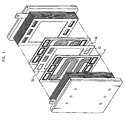
Fig. 1 illustrates an embodiment of the polymer electrolyte fuel cell, which comprises a membrane electrode assembly(MEA, 10) comprising a polymer electrolyte membrane and an electrode, a gas diffusion layer(fluid distribution layer, 12) delivering the gas used in a reaction to the electrode and discharging the reaction products, a conductive bipolar plate(separator, 14) supplying a reaction gas and a coolant from outside and separating oxidized electrode(anode) from deoxidized electrode(cathode), and the like. A fuel cell is composed by stacking these membrane electrode assembly, gas diffusion layer and bipolar plate as many as necessary, and the stack forms a single body with an appropriate pressure given from outside by a equipment, so each unit cell is not out of line or slipped. - Also, a number of manifolds(20) are formed in the upper part and the lower part of the membrane electrode assembly(10) and the bipolar plate(14) for supplying or discharging hydrogen, oxygen needed in a reaction, and coolant needed to cool the reaction heat. And hydrogen, oxygen and coolant supplied from outside are taken into the electrode passing through a pipe outside the stack, the manifold of the bipolar plate, and a gas-flow path formed on the bipolar plate of each unit cell.
- On the other hand, a sealing means should be included to prevent hydrogen, oxygen and coolant from leaking from each manifold and the reaction site where hydrogen and oxygen react. However, in the fuel cell, often stopping are repeated by its own characteristics, and expansion and contraction are frequently occurred during the fuel cell operation because of the heat generated by the chemical reaction. Therefore, a sealing structure for the fuel cell must exert sealing performance in the case of frequent expansion and contraction, and only if the stress distribution arising in each element of fuel cell in expansion and contraction is as uniform as possible, the fatigue failure can be prevented.
- For this, a gasket is disposed around the electrode and manifold. As a gasket for sealing the fuel cell, silicon sheet or Teflon sheet strengthened by glass fibers is often used because of its easy manufacturing advantage and little thickness deviation.
- This strengthened silicon sheet or Teflon sheet has an excellent mechanical strength supported by internal glass fibers, so it can exert mechanical toughness under the excessive pressure in the time when a stack is bound. But the rate of contraction and restoration are not so high that, when the fuel cell operates, gas is apprehended to leak for the expansion of parts by heat and water. Moreover gas can leak through the surface of the gasket because the surface is rough and the material is relatively hard.
- Another defect is that, if formed thicker than a gas diffusion layer when a stack is bound, the resistance increases because the mechanical strength is greater than that of a carbon paper or a carbon cloth generally used as a gas diffusion layer, and the contact between a gas diffusion layer and a bipolar plate is not tight. On the contrary, there is a problem that, if formed too thin, gas leaks because the pressure on the surface of the gasket is not enough. Therefore it is difficult to determine the proper thickness.
- Another way for sealing the fuel cell is to use rubber with superior elastic restitution force and soft property containing silicon, fluorine or olefin as a material of a gasket. There are the way of manufacturing a gasket in the shape of O-ring using a metal mold, the way of jet molding with a metal mold being placed directly on a bipolar plate, and the way of manufacturing a gasket using a dispenser, etc in the way of manufacturing a gasket of rubber.
- The way of manufacturing a gasket in the shape of O-ring using a metal mold has the defect that, after manufacturing a gasket, it must be placed on the surface of a bipolar plate one by one when a stack is bound. And the way of jet molding with a metal mold being placed directly on a bipolar plate has the defect that, in the time of manufacturing a gasket, the shape and the dimension of a metal mold must be same with the gasket.
- Also, the conventional way of manufacturing a gasket using a dispenser is the way of putting sealant in an injector and the like and pressing it, so has the problem that the height of rubber at starting point and ending point cannot be set uniformly. That is, the liquid state of rubber material is filled along a route of a sealing groove using a dispenser operated by X-Y axis robot, after forming the sealing groove in advance on a bipolar plate, with a width and a depth. The rubber overlaps in ending point with that of starting point, so height become greater than that of other part.
- Hereby the pressure of the surface on the bipolar plate and the membrane electrode assembly become nonuniform when a stack is bound, so not only sealing performance is lowered but also the life span of fatigue failure is shortened by this nonuniform stress distribution when used in the case of long term repeatedly.
-
US6,261,711 discloses a fluid seal for a fuel cell that includes a compressible member on a first fluid flow plate and a gasket disposed within a groove on a second fluid flow plate. -
WO 03/007408 - The present invention was invented to overcome the defects of conventional technologies, and it is an object of the present invention to provide a sealing structure for polymer electrolyte fuel cell whose structure not only does not lower the sealing performance although the thickness deviation of a gasket occurs, but also can disperse nonuniform stress distribution onto a bipolar plate and a membrane electrode assembly.
- It is another object of the present invention to provide a sealing structure for polymer electrolyte fuel cell wherein rubber is filled in a sealing groove formed on a bipolar plate using a dispenser comparatively easy to handle, to have entirely uniform height, to improve sealing performance by preventing the nonuniform pressure on a surface, and to extend the life span of products.
- According to a first aspect of the invention there is provided a sealing structure as set out in Claim 1. The preferred features of this aspect are as set out in Claims 2-9
- That is, according to the present invention, the thickness deviation in a gasket can be softened by interposing a gasket between a rubber and a membrane electrode assembly after filling rubber in a sealing groove formed on a bipolar plate using a dispenser. Also, nonuniform stress distribution can be resolved because a gasket covers with a pressure despite the height deviation of rubber, and a stress is not directly transmitted to a membrane electrode assembly and dispersed by a gasket despite nonuniform stress distribution.
- It is desirable that the sealing groove is formed in the perimeter of the reaction site of bipolar plate, and the perimeter of the manifold of hydrogen, oxygen and coolant as well.
- On the other hand, in the case of using a dispenser, because the difference of height between at starting point and at ending point is relatively greater than that of other parts, it is desirable to further comprise an anchor in contact with the sealing groove, whose width is greater than the width of the sealing groove.
- That is, by filling rubber by controlling a dispenser to start from the anchor and end in the anchor, the height of starting point and ending point can be uniform. And the width of the anchor is wide enough, although the height increases temporarily by the partial overlapping of starting point with ending point, the height becomes uniform by the diffusing of rubber right and left.
- It is preferable that the anchor has a width of 1.5 times of the width of the sealing groove. Thereby, damaging the sealing performance, with the rubber being diffused excessively and thinner than that of sealing groove, can be prevented effectively.
- Also, it is desirable that the sealing groove and the anchor have same depth, for a dispenser to move at uniform speed. Because, in the case that the depth of an anchor is different from the depth of sealing groove, the nonuniform moving speed of a dispenser can be brought about to fill up to the surface of groove.
- On the other hand, an anchor can be located anywhere only if it is contacted with the sealing groove. That is, by expanding the partial width of sealing groove right and left, an anchor can be formed. But, it is more desirable that the anchor is formed vertically to a route direction of the sealing groove in the periphery of the sealing groove.
- That is, on the characteristic of working, the height of rubber filled in an anchor portion is greater than the height of rubber filled in a sealing groove portion, and when the bipolar plate is bound to a fuel cell stack relatively more force is given to the perimeter of a bipolar plate than inner part. Therefore, by forming an anchor in the periphery of sealing site, the pressure given to the perimeter can be absorbed effectively, and consequently the pressure given to the entire bipolar plate can be distributed uniformly. In this respect, it is more desirable that the anchors on each of the bipolar plate located in the front and the rear of said membrane electrode assembly, are located symmetrically to each other when a fuel cell bound to a stack.
- On the other hand, the rubber is made of any of rubber materials containing silicon, fluorine or olefin.
- Also, it is desirable that the gasket is manufactured of the same material with the bipolar plate by this the deformation and nonuniform stress distribution caused by the difference of heat expansion rate can be prevented.
- Also, the present invention includes a polymer electrolyte fuel cell comprising the sealing structure above-mentioned.
-
-
Fig. 1 is an exploded perspective view for illustrating general structure of polymer electrolyte fuel cell. -
Fig. 2 is a front side elevation view illustrating bipolar plate in an embodiment of sealing structure of polymer electrolyte fuel cell according to the present invention. -
Fig. 3 is a perspective view illustrating A portion inFig. 2 enlarged. -
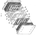
Fig. 4 is a view equivalent toFig. 1 illustrating polymer electrolyte fuel cell applied to by bipolar plate illustrated inFig. 2 . -
Fig. 5 is a vertical cross section view illustrating the pre-assembled state of polymer electrolyte fuel cell illustrated inFig. 4 . -
Fig. 6 is a vertical cross section view illustrating the assembled state of polymer electrolyte fuel cell illustrated inFig. 5 . - Hereinafter, an embodiment of polymer electrolyte fuel cell according to the present invention will be described in more detail with reference to the accompanying drawings. Also, in the present invention, the basic functional principle and process of fuel cell are same with that of conventional things, so the explanation for these is omitted.
- Referring to
Fig. 2 , in the central part ofBipolar plate 100 of the embodiment, areaction site 102 where hydrogen reacts with oxygen is formed, in theupper part manifold lower part manifold 104', 106', 108' to discharge each of coolant, oxygen and hydrogen are formed. - The
Bipolar plate 100 plays the role that hydrogen and oxygen do not mixed in a fuel cell, and that membrane electrode assembly is connected electrically, and functions as mechanical supporter of stacked unit cells. Also it functions that reaction gas flows to electrode evenly, membrane is not dry through adequate water management, and water created in deoxidation electrode is discharged. As the material ofbipolar plate 100 graphite or carbon composite can be used, and also metallic plate is used. In the case of metallic plate is used, it can be eroded so it is necessary to coat the surface with high-conductive, anticorrosive material. In this embodiment carbon composite is used asbipolar plate 100. - On the other hand, in the perimeter of the reaction site and each manifold, sealing
grooves 110, 110' are formed, inFig. 2 andFig. 3 the sealing grooves filled with rubber are illustrated. Here, in the lower left part of the sealinggroove 110 located in a reaction site, theanchor 112 which has the width of 1.5 times of the width of the sealinggroove 110 is formed to be extended toward the outside ofbipolar plate 100. The sealing groove and the anchor can be formed by CNC processing or press metallic pattern etc., the sealinggroove 110 is formed to have the depth of 0.3mm and the width of 2mm in the illustrated embodiment, and theanchor 112 is formed to have the depth of 0.3mm and the width of 3mm. In this time, rubber is discharged from a dispenser(not illustrated) with the width of 1.2mm and the height of 0.60mm. That is, rubber is filled in a sealing groove in the state of partially projected from the surface of bipolar plate, and the definite dimension of a sealing groove and an anchor is changeable according to the required capacity and the size of fuel cell. - As illustrated in
Fig. 3 , if the filling work of rubber start from theanchor 112 and finish in theanchor 112, because the anchor is formed widely enough, although the height of rubber filled in is nonuniform, it is diffused right and left, the starting point overlap with the ending point, and the height of the rubber becomes uniform. - After rubber is filled in a sealing groove and an anchor, if bipolar plate is heat-treated in the oven of 100 °C for 30 minutes, liquid rubber dried into solid. On the other hand, rubber is filled in the perimeter of the hydrogen, oxygen and coolant manifold as well in the same way with above.
- Referring to
Fig. 4 - 6 , ordinarymembrane electrode assembly 300 is located in the center of a fuel cell using abovebipolar plate 100, a couple ofgasket 200, 200' are in contact with the front and rear side ofmembrane electrode assembly 300, bored in the portion of 202, 204, 206, 208, 206', 208' each corresponding to thereaction site 102, hydrogen, oxygen andcoolant manifold bipolar plate 100, 100' are adhered to the outside. - A couple of
gas diffusion layer 310, 310' are adhered to the central front and rear side of themembrane electrode assembly 300, and the edge of theportion 202 of thegasket 200 corresponding to reaction site is adhered to, in contact, the side of thegas diffusion layer 310, somembrane electrode assembly 300 function as structural supporter to uniform the entire thickness. Above hydrogen, oxygen andcoolant manifold membrane electrode assembly 300. - In
Fig. 5 therubber 110, 110' is projected from the surface in a certain amount, but in the assembled state illustrated inFig. 6 the rubber maintains the state of pressed and adhered by the surface of thegasket 200, so the leakage can be prevented by the rubber although the thickness of gasket is nonuniform. Also, not because the stress given by the counter-force from the press of rubber is not directly transmitted to membrane electrode assembly, but because it is transmitted uniformly diffused through the gasket, the deformation and the destruction by nonuniform stress distribution is prevented. - According to the present invention comprised as above mentioned, not only sealing performance is highly improved because a rubber and a gasket seal doubly, but also in the case the surface of rubber or gasket is nonuniform it is buffered and supplemented by the interaction, it is a merit that if used for long term repeatedly, initial sealing performance can be maintained as it is.
- That is, although the deviation is occurred in the thickness of a gasket, it is in contact with the rubber partially projected from a bipolar plate, and the minuteness can be lowered in the time of gasket processing, so not only manufacturing cost can be reduced but also design can be accomplished more flexibly. And, in the case that the surface of rubber discharged by a dispenser is nonuniform, not only perfect sealing is possible because it is assembled in the state that the surface of a gasket is compressed but also the problem by nonuniform stress distribution can be minimized because the stress generated by rubber, even if not uniform, is transmitted to membrane electrode assembly diffused through gasket.
- Also, by setting up an anchor in a part of a sealing groove filled with rubber, there is an effect that not only height deviation in the starting point and the ending point of rubber filled by a dispenser can be minimized, but also production cost can be reduced by reducing the loss of the rubber material.
Claims (9)
- A sealing structure for polymer electrolyte fuel cell comprising:a bipolar plate (100) with sealing groove (110) filled with rubber; anda gaskat plate (200) interposed between said bipolar plate (100) and a membrane electrode assembly (300), wherein the rubber filling the sealing groove is interposed between the bipolar plate and the gasket plate such that the rubber filling the sealing groove seals the gasket plate with the bipolar plate.
- A sealing structure for polymer electrolyte fuel cell as in. Claim 1, further comprising an anchor (112) in contact with said sealing groove (110), whose width is greater than the width of said sealing groove (110).
- A sealing structure for polymer electrolyte fuel cell as in Claim 2, wherein said anchor (112) has a width of 1.5 times of the width of said sealing groove (110).
- A sealing structure for polymer electrolyte fuel cell as in Claim 3, wherein said sealing groove (110) and said anchor (112) have same depth.
- A sealing structure for polymer electrolyte fuel cell as in Claim 1, wherein said anchor (112) extends towards the outside of said sealing groove (110) and is perpendicular to said sealing groove (110).
- A sealing structure for polymer electrolyte fuel cell as in Claim 5, wherein two said bipolar plates (100, 101') are located at the front and rear of said membrane electrode assembly (300), are the said anchors (112) formed in said bipolar plates (100, 101') are located symmetrically to each other with respect to said membrane electrode assembly (300).
- A sealing structure for polymer electrolyte fuel cell as in Claim 1, wherein said rubber is made of any rubber materials containing silicon, fluorine or olefin.
- A sealing structure for polymer electrolyte fuel cell as in Claim 1, wherein said gasket plate (zero) is manufactured of the same material as said bipolar plate (100).
- A polymer electrolyte fuel cell comprising said sealing structure stated in any of Claims 1-8.
Applications Claiming Priority (2)
| Application Number | Priority Date | Filing Date | Title |
|---|---|---|---|
| KR10-2003-0035241A KR100537726B1 (en) | 2003-06-02 | 2003-06-02 | A sealing structure for polymer electrolyte fuel cell |
| PCT/KR2003/001226 WO2004107488A1 (en) | 2003-06-02 | 2003-06-23 | A sealing structure forpolymer electrolyte fuel cell |
Publications (3)
| Publication Number | Publication Date |
|---|---|
| EP1649533A1 EP1649533A1 (en) | 2006-04-26 |
| EP1649533A4 EP1649533A4 (en) | 2007-08-15 |
| EP1649533B1 true EP1649533B1 (en) | 2012-09-26 |
Family
ID=36099578
Family Applications (1)
| Application Number | Title | Priority Date | Filing Date |
|---|---|---|---|
| EP03817081A Expired - Lifetime EP1649533B1 (en) | 2003-06-02 | 2003-06-23 | A sealing structure forpolymer electrolyte fuel cell |
Country Status (7)
| Country | Link |
|---|---|
| US (1) | US8420273B2 (en) |
| EP (1) | EP1649533B1 (en) |
| JP (1) | JP4331719B2 (en) |
| KR (1) | KR100537726B1 (en) |
| CN (1) | CN100353601C (en) |
| AU (1) | AU2003244245A1 (en) |
| WO (1) | WO2004107488A1 (en) |
Families Citing this family (14)
| Publication number | Priority date | Publication date | Assignee | Title |
|---|---|---|---|---|
| US6013591A (en) | 1997-01-16 | 2000-01-11 | Massachusetts Institute Of Technology | Nanocrystalline apatites and composites, prostheses incorporating them, and method for their production |
| DK176957B1 (en) * | 2007-07-18 | 2010-07-26 | Serenergy As | Improvements in gaskets and bipolar plates for PEM fuel cells |
| EP2034544A1 (en) * | 2007-09-07 | 2009-03-11 | Exergy Fuel Cells S.R.L. | Bipolar plate for fuel cells |
| CN101587959B (en) * | 2008-05-23 | 2012-05-16 | 大连融科储能技术发展有限公司 | An electrode frame and an all-vanadium liquid flow energy storage battery stack |
| US8911918B2 (en) * | 2010-02-08 | 2014-12-16 | GM Global Technology Operations LLC | Hybrid seal application process |
| KR101372027B1 (en) | 2012-12-28 | 2014-03-07 | 현대자동차주식회사 | Fuel cell stack |
| JP2015052771A (en) * | 2013-08-06 | 2015-03-19 | パナソニックIpマネジメント株式会社 | Display panel holding structure, and imaging apparatus |
| EP3032626B1 (en) * | 2013-08-08 | 2017-08-09 | Nissan Motor Co., Ltd | Membrane electrode assembly with frame, fuel cell single cell, and fuel cell stack |
| DE202014007977U1 (en) * | 2014-09-30 | 2015-11-12 | Reinz-Dichtungs-Gmbh | Electrochemical system |
| CN110224152B (en) * | 2019-05-30 | 2020-10-13 | 山东潍氢动力科技有限公司 | Fuel cell with double-sealing groove metal bipolar plate and silicon injection membrane electrode structure |
| DE102019209583A1 (en) * | 2019-07-01 | 2021-01-07 | Robert Bosch Gmbh | Electrochemical system unit with sealing elements |
| CN114464836B (en) * | 2022-01-18 | 2026-01-13 | 国鸿氢能科技(嘉兴)股份有限公司 | Sealing structure of integrated membrane electrode fuel cell |
| US12548784B2 (en) * | 2022-04-06 | 2026-02-10 | Hydrogenics Corporation | Raised feed channels to maintain planar bipolar plate alignment |
| KR102621204B1 (en) * | 2022-08-26 | 2024-01-05 | 에스퓨얼셀(주) | Separator for fuel cell and fuel cell stack comprising the same |
Citations (1)
| Publication number | Priority date | Publication date | Assignee | Title |
|---|---|---|---|---|
| US20020055032A1 (en) * | 2000-11-06 | 2002-05-09 | Honda Giken Kogyo Kabushiki Kaisha | Sealing member for fuel cell |
Family Cites Families (17)
| Publication number | Priority date | Publication date | Assignee | Title |
|---|---|---|---|---|
| US4533455A (en) * | 1980-10-14 | 1985-08-06 | Oronzio De Nora Impianti Elettrochimici S.P.A. | Bipolar separator plate for electrochemical cells |
| US6337120B1 (en) * | 1998-06-26 | 2002-01-08 | Nok Corporation | Gasket for layer-built fuel cells and method for making the same |
| JP3951484B2 (en) * | 1998-12-16 | 2007-08-01 | トヨタ自動車株式会社 | Fuel cell |
| DE19908555A1 (en) * | 1999-02-27 | 2000-09-28 | Freudenberg Carl Fa | Sealing arrangement for large thin parts |
| AU3234200A (en) * | 1999-03-10 | 2000-09-28 | Flexfab Horizons International, Inc. | Fuel cell gasket assembly and method of assembling fuel cells |
| US6261711B1 (en) * | 1999-09-14 | 2001-07-17 | Plug Power Inc. | Sealing system for fuel cells |
| CA2345852C (en) | 2000-05-02 | 2008-11-18 | Honda Giken Kogyo Kabushiki Kaisha | Fuel cell having sealant for sealing a solid polymer electrolyte membrane |
| JP2001349436A (en) * | 2000-06-07 | 2001-12-21 | Uchiyama Mfg Corp | Gasket |
| JP2002042835A (en) | 2000-07-19 | 2002-02-08 | Mitsubishi Heavy Ind Ltd | Sealing structure of fuel cell |
| JP3400415B2 (en) * | 2000-07-25 | 2003-04-28 | 本田技研工業株式会社 | Fuel cell seal structure |
| EP1793438B1 (en) * | 2000-08-17 | 2013-07-10 | Panasonic Corporation | Polymer electrolyte fuel cell |
| JP4043724B2 (en) | 2001-02-14 | 2008-02-06 | 本田技研工業株式会社 | Unit fuel cell and fuel cell stack manufacturing method |
| US6852439B2 (en) | 2001-05-15 | 2005-02-08 | Hydrogenics Corporation | Apparatus for and method of forming seals in fuel cells and fuel cell stacks |
| JP2003017093A (en) | 2001-07-03 | 2003-01-17 | Nok Corp | Gasket for fuel cell |
| EP1416554B1 (en) * | 2001-07-06 | 2010-06-23 | Honda Giken Kogyo Kabushiki Kaisha | Method for coating a sealant on a fuel cell separator |
| CA2451111C (en) | 2001-07-11 | 2010-09-07 | Akiyoshi Machida | Method of coating fuel cell separator with seal material |
| EP1302996A3 (en) * | 2001-10-16 | 2006-04-19 | Matsushita Electric Industrial Co., Ltd. | Polymer electrolyte fuel cell |
-
2003
- 2003-06-02 KR KR10-2003-0035241A patent/KR100537726B1/en not_active Expired - Lifetime
- 2003-06-23 WO PCT/KR2003/001226 patent/WO2004107488A1/en not_active Ceased
- 2003-06-23 US US10/542,642 patent/US8420273B2/en not_active Expired - Fee Related
- 2003-06-23 EP EP03817081A patent/EP1649533B1/en not_active Expired - Lifetime
- 2003-06-23 JP JP2005500258A patent/JP4331719B2/en not_active Expired - Lifetime
- 2003-06-23 AU AU2003244245A patent/AU2003244245A1/en not_active Abandoned
- 2003-06-23 CN CNB038264994A patent/CN100353601C/en not_active Expired - Lifetime
Patent Citations (1)
| Publication number | Priority date | Publication date | Assignee | Title |
|---|---|---|---|---|
| US20020055032A1 (en) * | 2000-11-06 | 2002-05-09 | Honda Giken Kogyo Kabushiki Kaisha | Sealing member for fuel cell |
Also Published As
| Publication number | Publication date |
|---|---|
| EP1649533A4 (en) | 2007-08-15 |
| US8420273B2 (en) | 2013-04-16 |
| CN100353601C (en) | 2007-12-05 |
| EP1649533A1 (en) | 2006-04-26 |
| CN1771621A (en) | 2006-05-10 |
| JP2006526249A (en) | 2006-11-16 |
| KR100537726B1 (en) | 2005-12-19 |
| JP4331719B2 (en) | 2009-09-16 |
| AU2003244245A1 (en) | 2005-01-21 |
| KR20040103265A (en) | 2004-12-08 |
| WO2004107488A1 (en) | 2004-12-09 |
| US20060068263A1 (en) | 2006-03-30 |
Similar Documents
| Publication | Publication Date | Title |
|---|---|---|
| US8420273B2 (en) | Sealing structure for polymer electrolyte fuel cell | |
| US7063911B1 (en) | Gasket for fuel cell and method of forming it | |
| EP1271678B1 (en) | Systems, apparatus and methods for bonding and/or sealing electrochemical cell elements and assemblies | |
| US7534517B2 (en) | Fuel cell and method for manufacture thereof | |
| US6872485B2 (en) | Sealing structure for fuel cell | |
| JP5683433B2 (en) | Fuel cell stack | |
| US8262967B2 (en) | Gasket molding system for membrane electrode assemblies | |
| KR20010071677A (en) | Gas-proof assembly composed of a bipolar plate and a membrane-electrode unit of polymer electrolyte membrane fuel cells | |
| US11876255B2 (en) | Sealing arrangement, plate assembly, electrochemical system, and method for producing a sealing arrangement | |
| JP2004527872A (en) | Electrochemical cell stack | |
| CN114303265B (en) | Electrochemical system unit with sealing element | |
| JP4224439B2 (en) | Fuel cell | |
| US20210126275A1 (en) | Electrochemical device | |
| US8168347B2 (en) | SOFC assembly joint spacing | |
| US20060083977A1 (en) | Fuel cell | |
| JP4963589B2 (en) | Fuel cell stack | |
| JP4214027B2 (en) | Fuel cell | |
| JP4069039B2 (en) | Fuel cell | |
| WO2016083307A1 (en) | Fuel cell component and method of manufacturing of a fuel cell component | |
| CN112470313A (en) | Bipolar plate for fuel cell and fuel cell | |
| KR20200069452A (en) | Separator assembly for fuel cell and Fuel cell stack including the same | |
| JP4734880B2 (en) | Fuel cell | |
| JP2008520069A (en) | Fuel cell stack receiving external media supply | |
| US20220190360A1 (en) | Separator for fuel cell and method for manufacturing separator | |
| JP4963590B2 (en) | Fuel cell |
Legal Events
| Date | Code | Title | Description |
|---|---|---|---|
| PUAI | Public reference made under article 153(3) epc to a published international application that has entered the european phase |
Free format text: ORIGINAL CODE: 0009012 |
|
| 17P | Request for examination filed |
Effective date: 20051227 |
|
| AK | Designated contracting states |
Kind code of ref document: A1 Designated state(s): AT BE BG CH CY CZ DE DK EE ES FI FR GB GR HU IE IT LI LU MC NL PT RO SE SI SK TR |
|
| DAX | Request for extension of the european patent (deleted) | ||
| RIN1 | Information on inventor provided before grant (corrected) |
Inventor name: OH, SUNG-JIN; Inventor name: HONG, BYUNG-SUN Inventor name: SHINN, MEE-NAM Inventor name: KIM, HO-SUK Inventor name: YANG, CHEOL-NAM807-601 JEONGDEUN MAEUL Inventor name: SEO, YONG-JUNG; |
|
| A4 | Supplementary search report drawn up and despatched |
Effective date: 20070716 |
|
| 17Q | First examination report despatched |
Effective date: 20080417 |
|
| GRAP | Despatch of communication of intention to grant a patent |
Free format text: ORIGINAL CODE: EPIDOSNIGR1 |
|
| GRAS | Grant fee paid |
Free format text: ORIGINAL CODE: EPIDOSNIGR3 |
|
| GRAA | (expected) grant |
Free format text: ORIGINAL CODE: 0009210 |
|
| AK | Designated contracting states |
Kind code of ref document: B1 Designated state(s): AT BE BG CH CY CZ DE DK EE ES FI FR GB GR HU IE IT LI LU MC NL PT RO SE SI SK TR |
|
| REG | Reference to a national code |
Ref country code: DE Ref legal event code: R081 Ref document number: 60342222 Country of ref document: DE Owner name: DOOSAN CORP., KR Free format text: FORMER OWNER: FUELCELLPOWER CO. LTD., GYEONGGI-DO, KR Ref country code: GB Ref legal event code: FG4D |
|
| REG | Reference to a national code |
Ref country code: CH Ref legal event code: EP |
|
| REG | Reference to a national code |
Ref country code: AT Ref legal event code: REF Ref document number: 577389 Country of ref document: AT Kind code of ref document: T Effective date: 20121015 |
|
| REG | Reference to a national code |
Ref country code: IE Ref legal event code: FG4D |
|
| REG | Reference to a national code |
Ref country code: DE Ref legal event code: R096 Ref document number: 60342222 Country of ref document: DE Effective date: 20121122 |
|
| REG | Reference to a national code |
Ref country code: NL Ref legal event code: T3 |
|
| PG25 | Lapsed in a contracting state [announced via postgrant information from national office to epo] |
Ref country code: FI Free format text: LAPSE BECAUSE OF FAILURE TO SUBMIT A TRANSLATION OF THE DESCRIPTION OR TO PAY THE FEE WITHIN THE PRESCRIBED TIME-LIMIT Effective date: 20120926 |
|
| REG | Reference to a national code |
Ref country code: AT Ref legal event code: MK05 Ref document number: 577389 Country of ref document: AT Kind code of ref document: T Effective date: 20120926 |
|
| PG25 | Lapsed in a contracting state [announced via postgrant information from national office to epo] |
Ref country code: GR Free format text: LAPSE BECAUSE OF FAILURE TO SUBMIT A TRANSLATION OF THE DESCRIPTION OR TO PAY THE FEE WITHIN THE PRESCRIBED TIME-LIMIT Effective date: 20121227 Ref country code: SI Free format text: LAPSE BECAUSE OF FAILURE TO SUBMIT A TRANSLATION OF THE DESCRIPTION OR TO PAY THE FEE WITHIN THE PRESCRIBED TIME-LIMIT Effective date: 20120926 Ref country code: SE Free format text: LAPSE BECAUSE OF FAILURE TO SUBMIT A TRANSLATION OF THE DESCRIPTION OR TO PAY THE FEE WITHIN THE PRESCRIBED TIME-LIMIT Effective date: 20120926 |
|
| PG25 | Lapsed in a contracting state [announced via postgrant information from national office to epo] |
Ref country code: CZ Free format text: LAPSE BECAUSE OF FAILURE TO SUBMIT A TRANSLATION OF THE DESCRIPTION OR TO PAY THE FEE WITHIN THE PRESCRIBED TIME-LIMIT Effective date: 20120926 Ref country code: ES Free format text: LAPSE BECAUSE OF FAILURE TO SUBMIT A TRANSLATION OF THE DESCRIPTION OR TO PAY THE FEE WITHIN THE PRESCRIBED TIME-LIMIT Effective date: 20130106 Ref country code: BE Free format text: LAPSE BECAUSE OF FAILURE TO SUBMIT A TRANSLATION OF THE DESCRIPTION OR TO PAY THE FEE WITHIN THE PRESCRIBED TIME-LIMIT Effective date: 20120926 Ref country code: EE Free format text: LAPSE BECAUSE OF FAILURE TO SUBMIT A TRANSLATION OF THE DESCRIPTION OR TO PAY THE FEE WITHIN THE PRESCRIBED TIME-LIMIT Effective date: 20120926 Ref country code: RO Free format text: LAPSE BECAUSE OF FAILURE TO SUBMIT A TRANSLATION OF THE DESCRIPTION OR TO PAY THE FEE WITHIN THE PRESCRIBED TIME-LIMIT Effective date: 20120926 |
|
| PG25 | Lapsed in a contracting state [announced via postgrant information from national office to epo] |
Ref country code: SK Free format text: LAPSE BECAUSE OF FAILURE TO SUBMIT A TRANSLATION OF THE DESCRIPTION OR TO PAY THE FEE WITHIN THE PRESCRIBED TIME-LIMIT Effective date: 20120926 Ref country code: CY Free format text: LAPSE BECAUSE OF FAILURE TO SUBMIT A TRANSLATION OF THE DESCRIPTION OR TO PAY THE FEE WITHIN THE PRESCRIBED TIME-LIMIT Effective date: 20120926 Ref country code: PT Free format text: LAPSE BECAUSE OF FAILURE TO SUBMIT A TRANSLATION OF THE DESCRIPTION OR TO PAY THE FEE WITHIN THE PRESCRIBED TIME-LIMIT Effective date: 20130128 |
|
| PG25 | Lapsed in a contracting state [announced via postgrant information from national office to epo] |
Ref country code: AT Free format text: LAPSE BECAUSE OF FAILURE TO SUBMIT A TRANSLATION OF THE DESCRIPTION OR TO PAY THE FEE WITHIN THE PRESCRIBED TIME-LIMIT Effective date: 20120926 |
|
| PG25 | Lapsed in a contracting state [announced via postgrant information from national office to epo] |
Ref country code: DK Free format text: LAPSE BECAUSE OF FAILURE TO SUBMIT A TRANSLATION OF THE DESCRIPTION OR TO PAY THE FEE WITHIN THE PRESCRIBED TIME-LIMIT Effective date: 20120926 Ref country code: BG Free format text: LAPSE BECAUSE OF FAILURE TO SUBMIT A TRANSLATION OF THE DESCRIPTION OR TO PAY THE FEE WITHIN THE PRESCRIBED TIME-LIMIT Effective date: 20121226 |
|
| PLBE | No opposition filed within time limit |
Free format text: ORIGINAL CODE: 0009261 |
|
| STAA | Information on the status of an ep patent application or granted ep patent |
Free format text: STATUS: NO OPPOSITION FILED WITHIN TIME LIMIT |
|
| PG25 | Lapsed in a contracting state [announced via postgrant information from national office to epo] |
Ref country code: IT Free format text: LAPSE BECAUSE OF FAILURE TO SUBMIT A TRANSLATION OF THE DESCRIPTION OR TO PAY THE FEE WITHIN THE PRESCRIBED TIME-LIMIT Effective date: 20120926 |
|
| 26N | No opposition filed |
Effective date: 20130627 |
|
| REG | Reference to a national code |
Ref country code: DE Ref legal event code: R097 Ref document number: 60342222 Country of ref document: DE Effective date: 20130627 |
|
| PG25 | Lapsed in a contracting state [announced via postgrant information from national office to epo] |
Ref country code: MC Free format text: LAPSE BECAUSE OF FAILURE TO SUBMIT A TRANSLATION OF THE DESCRIPTION OR TO PAY THE FEE WITHIN THE PRESCRIBED TIME-LIMIT Effective date: 20120926 |
|
| REG | Reference to a national code |
Ref country code: CH Ref legal event code: PL |
|
| REG | Reference to a national code |
Ref country code: IE Ref legal event code: MM4A |
|
| PG25 | Lapsed in a contracting state [announced via postgrant information from national office to epo] |
Ref country code: LI Free format text: LAPSE BECAUSE OF NON-PAYMENT OF DUE FEES Effective date: 20130630 Ref country code: IE Free format text: LAPSE BECAUSE OF NON-PAYMENT OF DUE FEES Effective date: 20130623 Ref country code: CH Free format text: LAPSE BECAUSE OF NON-PAYMENT OF DUE FEES Effective date: 20130630 |
|
| REG | Reference to a national code |
Ref country code: DE Ref legal event code: R082 Ref document number: 60342222 Country of ref document: DE Representative=s name: MARKS & CLERK (LUXEMBOURG) LLP, LU Ref country code: DE Ref legal event code: R081 Ref document number: 60342222 Country of ref document: DE Owner name: DOOSAN CORP., KR Free format text: FORMER OWNER: FUELCELLPOWER CO. LTD., GYEONGGI-DO, KR |
|
| PG25 | Lapsed in a contracting state [announced via postgrant information from national office to epo] |
Ref country code: TR Free format text: LAPSE BECAUSE OF FAILURE TO SUBMIT A TRANSLATION OF THE DESCRIPTION OR TO PAY THE FEE WITHIN THE PRESCRIBED TIME-LIMIT Effective date: 20120926 |
|
| PG25 | Lapsed in a contracting state [announced via postgrant information from national office to epo] |
Ref country code: HU Free format text: LAPSE BECAUSE OF FAILURE TO SUBMIT A TRANSLATION OF THE DESCRIPTION OR TO PAY THE FEE WITHIN THE PRESCRIBED TIME-LIMIT; INVALID AB INITIO Effective date: 20030623 Ref country code: LU Free format text: LAPSE BECAUSE OF NON-PAYMENT OF DUE FEES Effective date: 20130623 |
|
| REG | Reference to a national code |
Ref country code: NL Ref legal event code: SD Effective date: 20150805 Ref country code: NL Ref legal event code: TD Effective date: 20150805 |
|
| REG | Reference to a national code |
Ref country code: FR Ref legal event code: RM Effective date: 20150812 Ref country code: FR Ref legal event code: TP Owner name: DOOSAN CORPORATION, KR Effective date: 20150812 |
|
| REG | Reference to a national code |
Ref country code: GB Ref legal event code: S117 Free format text: REQUEST FILED; REQUEST FOR CORRECTION UNDER SECTION 117 FILED ON 26 MAY 2015. |
|
| REG | Reference to a national code |
Ref country code: GB Ref legal event code: S117 Free format text: CORRECTIONS ALLOWED; REQUEST FOR CORRECTION UNDER SECTION 117 FILED ON 26 MAY 2015, ALLOWED ON 27 AUGUST 2015. |
|
| REG | Reference to a national code |
Ref country code: GB Ref legal event code: 732E Free format text: REGISTERED BETWEEN 20150917 AND 20150923 |
|
| REG | Reference to a national code |
Ref country code: FR Ref legal event code: PLFP Year of fee payment: 14 |
|
| REG | Reference to a national code |
Ref country code: FR Ref legal event code: PLFP Year of fee payment: 15 |
|
| REG | Reference to a national code |
Ref country code: FR Ref legal event code: PLFP Year of fee payment: 16 |
|
| PGFP | Annual fee paid to national office [announced via postgrant information from national office to epo] |
Ref country code: NL Payment date: 20220527 Year of fee payment: 20 |
|
| PGFP | Annual fee paid to national office [announced via postgrant information from national office to epo] |
Ref country code: GB Payment date: 20220519 Year of fee payment: 20 Ref country code: FR Payment date: 20220523 Year of fee payment: 20 Ref country code: DE Payment date: 20220517 Year of fee payment: 20 |
|
| REG | Reference to a national code |
Ref country code: DE Ref legal event code: R071 Ref document number: 60342222 Country of ref document: DE |
|
| REG | Reference to a national code |
Ref country code: NL Ref legal event code: MK Effective date: 20230622 |
|
| REG | Reference to a national code |
Ref country code: GB Ref legal event code: PE20 Expiry date: 20230622 |
|
| PG25 | Lapsed in a contracting state [announced via postgrant information from national office to epo] |
Ref country code: GB Free format text: LAPSE BECAUSE OF EXPIRATION OF PROTECTION Effective date: 20230622 |