EP1648167A1 - Television - Google Patents
Television Download PDFInfo
- Publication number
- EP1648167A1 EP1648167A1 EP05002912A EP05002912A EP1648167A1 EP 1648167 A1 EP1648167 A1 EP 1648167A1 EP 05002912 A EP05002912 A EP 05002912A EP 05002912 A EP05002912 A EP 05002912A EP 1648167 A1 EP1648167 A1 EP 1648167A1
- Authority
- EP
- European Patent Office
- Prior art keywords
- television
- rear cover
- circuit board
- electrical circuit
- control box
- Prior art date
- Legal status (The legal status is an assumption and is not a legal conclusion. Google has not performed a legal analysis and makes no representation as to the accuracy of the status listed.)
- Withdrawn
Links
- 230000000903 blocking effect Effects 0.000 claims abstract description 7
- 238000000034 method Methods 0.000 claims description 10
- 239000004973 liquid crystal related substance Substances 0.000 claims description 3
- 238000010586 diagram Methods 0.000 description 2
- 230000029305 taxis Effects 0.000 description 2
- 238000012423 maintenance Methods 0.000 description 1
- 230000001151 other effect Effects 0.000 description 1
- 230000005855 radiation Effects 0.000 description 1
Images


Classifications
-
- H—ELECTRICITY
- H04—ELECTRIC COMMUNICATION TECHNIQUE
- H04N—PICTORIAL COMMUNICATION, e.g. TELEVISION
- H04N5/00—Details of television systems
- H04N5/64—Constructional details of receivers, e.g. cabinets or dust covers
Definitions
- the present invention relates to a television, and more particularly, to a television that the user can disassemble the television control box without the necessity of disassembling the front cover and the rear cover.
- the flat display television has the advantage of lightness, small size, no radiation, and gentle display that cathode ray tube television does not have
- the flat display television gradually substitute the market share of the cathode ray tube television, and causes the main stream of the electrical appliances product, television, enter the time of flat and planar age.
- the present planar display television includes the plasma television that has a plasma display panel, the LCD television that has a liquid crystal display panel and the organic light-emitting diode television that has an organic light-emitting diode display panel.
- the plasma television is taken for example with some figures and descriptions as follows.
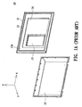
- Fig. 1A is the decomposed view of a conventional plasma television
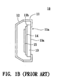
- Fig. 1B is the assembly cross sectional diagram of the plasma television shown in Fig. 1A which takes the yz plane as the cross sectional plane and views from the ⁇ x direction.
- the plasma television 10 includes a front cover 11, a rear cover 12, a plasma display panel 13, an electrical circuit board 14 and a television control box 15.
- the plasma display panel 13 has the relative front display area 13a and the rear non-display area 13b.
- the front cover 11 has a front cover aperture 11a, and the front cover aperture 11a is used to expose the front display area 13a of the plasma display panel 13.
- the electrical circuit board 14 is established on the rear non-display area 13b of the plasma display panel 13 and connected with the plasma display panel 13.
- the television control box 15 is connected with the electrical circuit board 14 by locking on the electrical circuit board 14.
- the front cover 11 is locked with the rear cover 12, and there are a plasma display panel 13, an electrical circuit board 14 and a television control box 15 placed between the front cover 11 and the rear cover 12.
- the television control box 15 is locked solidly inside the television 10
- the front cover 11 and the rear cover 12 must first be disassembled, then the television control box 10 can be examined. It takes time to disassemble the machine, and also increases the difficulty of service. As the television size grows bigger, the disassembly difficulty grows.
- the electrical components on the plasma display panel 13 and the electrical circuit board 14 could be hit, causing the nonessential damage, and increasing the television 10 services costs, which is quite uneconomical.
- an object of the present invention is to provide a television that the user can disassemble the television control box without the need to disassemble the front cover and the rear cover in advance.
- the television according to the present invention includes a front cover, a rear cover, a display panel, an electrical circuit board and a television control box.
- the front cover has a front cover aperture
- the rear cover is assembled with the front cover by buckling together
- the rear cover has a rear cover aperture.
- the display panel is set up between the front cover and the rear cover, and it has a relative front display area and a rear non-display area.
- the front cover aperture exposes the front display area, and the rear non-display area faces the rear cover.
- the electrical circuit board is setup at the rear non-display area, and connected with the display panel.
- the rear cover aperture exposes part of the electrical circuit board.
- the television control box is assembled on the electrical circuit board in the form of blocking up the rear cover aperture and then connected with the electrical circuit board. Wherein, the television control box may be taken out from the rear cover aperture and be separated from the electrical circuit board.
- the television 20 includes a front cover 21, a rear cover 22, a display panel 23, an electrical circuit board 24, a television control box 25 and a supporting seat 26.
- the rear cover 22 is assembled with the front cover 21 by buckling together along the y-axis, and the rear cover has a rear cover aperture 22a.
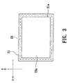
- the display panel 23 is disposed between the front cover 21 and the rear cover 22, and it has the relative front display area 23a and a rear non-display area 23b as shown in Fig. 3.
- the front cover 21 has a front cover aperture 21a and the front cover aperture 21a exposes the front display area 23a.
- the rear non-display area 23b faces the rear cover 22 and reversely face the front cover 21.
- the electrical circuit board 24 is disposed at the rear non-display area 23b, and connected with the display panel 23.
- the electrical circuit board 24 consists of a first connector 24a.
- the supporting seat 24 consists of two supporting rods 26a, and these two supporting rods are assembled with the front cover 21 or the rear cover 22 that the television 20 can be held in horizontal position by the supporting seat 26.
- the television control box 25 has a relative control box front 25a and a control box back 25b, a second connector 25c for connection and a terminal connection interface 25d.
- the second connector 25c and the terminal connection interface 25d are disposed on the control box front 25a and the control box back 25b respectively.
- the second connector 25c is connected with the first connector 24a through the rear cover aperture 22a along the y-axis by the method of hot plug.
- the television control box 25 is disposed on the electrical circuit board 24 by blocking the rear cover aperture 22a.
- the second connector 25c is separated from the first connector 24a as Fig.
- the television control box 25 can be taken out from the television 20 from the rear cover aperture 22a and be apart from the electrical circuit board.
- the terminal connection interface 25d exposes itself outside the television 20, and through an antenna or the cable line to receive at least one digital or analog television program signal.
- the terminal connection interface 25d is also capable of receiving the signal from the video and audio output device, like the output of analog voice signal from the television amusement, VCD player, DVD player and so on.
- step 61 the electrical circuit board 24 is disposed on the rear non-display area 23b of the display panel 23.
- the electrical circuit board 24 is connected with the display panel 23 and the display panel 23 consists of a front display area 23a relative to the rear non-display area 23b.
- step 62 a front cover 21 with a front cover aperture 21a is connected with a rear cover 22 with a rear cover aperture 22a, and the electrical circuit board 24 and the display panel 23 are disposed between them.
- the front cover aperture 21a exposes the front display area 23a, and the rear cover aperture 22a exposes part of the electrical circuit board 24. Then, in step 63, the television control box 25 is assembled with the electrical circuit board 24 by blocking the rear cover aperture 22a to be disposed on the electrical circuit board 24.
- the rear cover 22 has the rear cover aperture 22a for the user to inspect whether the television control box 25 is damaged and decide if it needs service by assembling and disassembling the television control box 25 without the need of disassembling the front cover 21 and rear cover 22 in advance.
- the user does not need to disassemble the front cover 21 and the rear cover 22, it prevents the user from hitting the electrical components of the display panel 23 and the electrical circuit board 24 inside the television 20 in order to prevent unnecessary damage and reduce the service cost of the television 20.
- the television 20 is exported in the way that the television control box 25 is separated from the electrical circuit board 24 to domestic or foreign places, it can reduce the transportation cost and save lots of taxes.
- the user can enjoy the DIY pleasure of assembling the television 20.
- the display panel 22 can be a plasma display panel, a liquid crystal display panel or an organic light-emitting diode display panel.
- the size of the television control box 25 is approximately equal to the rear cover aperture 22a.
- the television control box 25 can be assembled with the rear cover by buckling, wedging, or locking.
- the user can fix the television control box 25 on the rear cover 22 by a screw, a hole plug or filling a nail that the television control box 25 blocks the rear cover aperture 22a in order to achieve the goal of fast assembly and convenient disassembly.
- the television control box 25 can be connected with the electrical circuit board 24 through the rear cover aperture 22a
- the television control box 25 can be connected with the electrical circuit board 23 through any other electrically connecting types and is not limited in the method of hot plug and unplug.
- the electrical circuit board 24 consists of the electrical circuit designs of a display apparatus and a television
- the television without television control box 25 is regarded as a display apparatus, and it can be connected with a computer and be the monitor of the connected computer.
- the television in the preferred embodiment of the present invention discloses the design that the television control box can be assembled or disassembled with the electrical circuit board from the rear cover aperture. This can provide the user a way to assemble or take off the television control box without disassemble the front cover and the rear cover, and then the user may inspect the damage of the television control box and decide whether it needs service. Thus, it can save the maintenance man-hours, as well as reduces the difficulty for service.
- the user does not need to disassemble the front cover and the rear cover, it prevents the user from hitting the television interior display panel and electrical components of the electrical circuit board, and prevents nonessential damage and reduces the service cost.
- the television is exported in the way that the television control box is separated from the electrical circuit board to domestic or foreign places, it can reduce the transportation cost and save lots of taxes. Moreover, the user can enjoy the DIY (Do it yourself) pleasure of assembling the television.
Landscapes
- Engineering & Computer Science (AREA)
- Multimedia (AREA)
- Signal Processing (AREA)
- Devices For Indicating Variable Information By Combining Individual Elements (AREA)
Abstract
A television, having a front cover (21) with a front cover aperture, a rear cover (22) assembled with the front cover by buckling, and the rear cover with a rear cover aperture (22a). The display panel is disposed between the front cover and the rear cover, having a relative front display area and a rear non-display area (23b). The front cover aperture exposes the front display area, and the rear non-display area faces the rear cover. The electrical circuit board (24) is disposed on the rear non-display area, connected with the display panel. The rear cover aperture exposes part of the electrical circuit board. The television control box is assembled on the electrical circuit board by blocking the rear cover aperture and connected with the electrical circuit board. Wherein, the television control box can be taken out from the rear cover aperture and separated from the electrical circuit board.
Description
- The present invention relates to a television, and more particularly, to a television that the user can disassemble the television control box without the necessity of disassembling the front cover and the rear cover.
- Because the flat display television has the advantage of lightness, small size, no radiation, and gentle display that cathode ray tube television does not have, the flat display television gradually substitute the market share of the cathode ray tube television, and causes the main stream of the electrical appliances product, television, enter the time of flat and planar age. In addition, according to the type of the display panel, the present planar display television includes the plasma television that has a plasma display panel, the LCD television that has a liquid crystal display panel and the organic light-emitting diode television that has an organic light-emitting diode display panel. Here the plasma television is taken for example with some figures and descriptions as follows.
- Please refer to Fig. 1A ~ Fig. 1B, Fig. 1A is the decomposed view of a conventional plasma television, and Fig. 1B is the assembly cross sectional diagram of the plasma television shown in Fig. 1A which takes the yz plane as the cross sectional plane and views from the ―x direction. In Fig. 1A ~ Fig. 1B, the
plasma television 10 includes afront cover 11, arear cover 12, aplasma display panel 13, anelectrical circuit board 14 and atelevision control box 15. Theplasma display panel 13 has the relativefront display area 13a and therear non-display area 13b. Thefront cover 11 has a front cover aperture 11a, and the front cover aperture 11a is used to expose thefront display area 13a of theplasma display panel 13. Theelectrical circuit board 14 is established on therear non-display area 13b of theplasma display panel 13 and connected with theplasma display panel 13. Thetelevision control box 15 is connected with theelectrical circuit board 14 by locking on theelectrical circuit board 14. Thefront cover 11 is locked with therear cover 12, and there are aplasma display panel 13, anelectrical circuit board 14 and atelevision control box 15 placed between thefront cover 11 and therear cover 12. - Because the
television control box 15 is locked solidly inside thetelevision 10, if a user wants to inspect whether thetelevision control box 15 is damaged or not, thefront cover 11 and therear cover 12 must first be disassembled, then thetelevision control box 10 can be examined. It takes time to disassemble the machine, and also increases the difficulty of service. As the television size grows bigger, the disassembly difficulty grows. In addition, when the user disassembles thefront cover 11 and therear cover 12, if not carefully, the electrical components on theplasma display panel 13 and theelectrical circuit board 14 could be hit, causing the nonessential damage, and increasing thetelevision 10 services costs, which is quite uneconomical. - In view of this, an object of the present invention is to provide a television that the user can disassemble the television control box without the need to disassemble the front cover and the rear cover in advance.
- To accomplish the above objective, the television according to the present invention includes a front cover, a rear cover, a display panel, an electrical circuit board and a television control box. The front cover has a front cover aperture, the rear cover is assembled with the front cover by buckling together, and the rear cover has a rear cover aperture. The display panel is set up between the front cover and the rear cover, and it has a relative front display area and a rear non-display area. The front cover aperture exposes the front display area, and the rear non-display area faces the rear cover. The electrical circuit board is setup at the rear non-display area, and connected with the display panel. The rear cover aperture exposes part of the electrical circuit board. The television control box is assembled on the electrical circuit board in the form of blocking up the rear cover aperture and then connected with the electrical circuit board. Wherein, the television control box may be taken out from the rear cover aperture and be separated from the electrical circuit board.
-
- Fig. 1A is the decomposed view of a conventional plasma television.
- Fig. 1B is the assembly cross-sectional view of the plasma television in Fig. 1A by taking the yz-plane as the cross-sectional plane and viewing from the ―x direction.
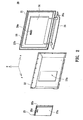
- Fig. 2 is the decomposed view of the television in the preferred embodiment of the present invention.
- Fig. 3 is the diagram of the front cover and the display panel in Fig. 2 from the y-direction.
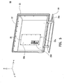
- Fig. 4 is the structural perspective view of the front cover, the rear cover, the display panel, the electrical circuit board and the supporting seat in Fig. 2.
- Fig. 5 is the assembly view of the television in the preferred embodiment of the present invention.
- Fig. 6 is the assembly process of the television in the preferred embodiment of the present invention.
- In order to reach the objective mentioned above, the technical method and other effects, a preferred embodiment is introduced with some figures and descriptions as follows.
- Please refer to Fig. 2; the drawing is the decomposed view of the television in the preferred embodiment of the present invention. In Fig. 2, the
television 20 includes afront cover 21, arear cover 22, adisplay panel 23, anelectrical circuit board 24, atelevision control box 25 and a supportingseat 26. Therear cover 22 is assembled with thefront cover 21 by buckling together along the y-axis, and the rear cover has arear cover aperture 22a. Thedisplay panel 23 is disposed between thefront cover 21 and therear cover 22, and it has the relativefront display area 23a and arear non-display area 23b as shown in Fig. 3. In Fig. 3, thefront cover 21 has afront cover aperture 21a and thefront cover aperture 21a exposes thefront display area 23a. - Please again refer to Fig. 2; the
rear non-display area 23b faces therear cover 22 and reversely face thefront cover 21. Theelectrical circuit board 24 is disposed at therear non-display area 23b, and connected with thedisplay panel 23. In addition, theelectrical circuit board 24 consists of afirst connector 24a. As Fig. 4 shows, when thefront cover 21 and therear cover 22 are assembled, and thedisplay panel 23 and theelectrical circuit board 24 are disposed between them, therear cover aperture 22a exposes part of theelectrical circuit board 24 and thefirst connector 24a. In addition, the supportingseat 24 consists of two supportingrods 26a, and these two supporting rods are assembled with thefront cover 21 or therear cover 22 that thetelevision 20 can be held in horizontal position by the supportingseat 26. - Please also refer to Fig. 2 and Fig. 4; the
television control box 25 has a relativecontrol box front 25a and acontrol box back 25b, asecond connector 25c for connection and aterminal connection interface 25d. Thesecond connector 25c and theterminal connection interface 25d are disposed on thecontrol box front 25a and the control box back 25b respectively. Thesecond connector 25c is connected with thefirst connector 24a through therear cover aperture 22a along the y-axis by the method of hot plug. When thesecond connector 25c is connected with thefirst connector 24a, as Fig. 5 shows, thetelevision control box 25 is disposed on theelectrical circuit board 24 by blocking therear cover aperture 22a. When thesecond connector 25c is separated from thefirst connector 24a as Fig. 4 shows, thetelevision control box 25 can be taken out from thetelevision 20 from therear cover aperture 22a and be apart from the electrical circuit board. In Fig. 5, theterminal connection interface 25d exposes itself outside thetelevision 20, and through an antenna or the cable line to receive at least one digital or analog television program signal. Besides, theterminal connection interface 25d is also capable of receiving the signal from the video and audio output device, like the output of analog voice signal from the television amusement, VCD player, DVD player and so on. - Please refer to Fig. 6; the drawing is the assembly flow chart of the television in the preferred embodiment of the present invention. Please also refer to Fig. 2 - Fig. 5, first of all, in
step 61, theelectrical circuit board 24 is disposed on the rearnon-display area 23b of thedisplay panel 23. Theelectrical circuit board 24 is connected with thedisplay panel 23 and thedisplay panel 23 consists of afront display area 23a relative to the rearnon-display area 23b. Instep 62, afront cover 21 with afront cover aperture 21a is connected with arear cover 22 with arear cover aperture 22a, and theelectrical circuit board 24 and thedisplay panel 23 are disposed between them. Thefront cover aperture 21a exposes thefront display area 23a, and therear cover aperture 22a exposes part of theelectrical circuit board 24. Then, instep 63, thetelevision control box 25 is assembled with theelectrical circuit board 24 by blocking therear cover aperture 22a to be disposed on theelectrical circuit board 24. - In the preferred embodiment, the
rear cover 22 has therear cover aperture 22a for the user to inspect whether thetelevision control box 25 is damaged and decide if it needs service by assembling and disassembling thetelevision control box 25 without the need of disassembling thefront cover 21 andrear cover 22 in advance. Thus, it can save the service man-hours, as well as reduce the difficulty of service. In addition, because the user does not need to disassemble thefront cover 21 and therear cover 22, it prevents the user from hitting the electrical components of thedisplay panel 23 and theelectrical circuit board 24 inside thetelevision 20 in order to prevent unnecessary damage and reduce the service cost of thetelevision 20. In addition, if thetelevision 20 is exported in the way that thetelevision control box 25 is separated from theelectrical circuit board 24 to domestic or foreign places, it can reduce the transportation cost and save lots of taxes. Moreover, the user can enjoy the DIY pleasure of assembling thetelevision 20. - However, one skilled in the art also can understand that the technique of the preferred embodiment is certainly not limited here. For example, the
display panel 22 can be a plasma display panel, a liquid crystal display panel or an organic light-emitting diode display panel. In addition, the size of thetelevision control box 25 is approximately equal to therear cover aperture 22a. When thetelevision control box 25 is assembled with theelectrical circuit board 24, thetelevision control box 25 can be assembled with the rear cover by buckling, wedging, or locking. For instance, the user can fix thetelevision control box 25 on therear cover 22 by a screw, a hole plug or filling a nail that thetelevision control box 25 blocks therear cover aperture 22a in order to achieve the goal of fast assembly and convenient disassembly. Under the presupposition that thetelevision control box 25 can be connected with theelectrical circuit board 24 through therear cover aperture 22a, thetelevision control box 25 can be connected with theelectrical circuit board 23 through any other electrically connecting types and is not limited in the method of hot plug and unplug. Under the assumption that theelectrical circuit board 24 consists of the electrical circuit designs of a display apparatus and a television, when thetelevision control box 25 is separated from the electrical circuit board, the television withouttelevision control box 25 is regarded as a display apparatus, and it can be connected with a computer and be the monitor of the connected computer. - The television in the preferred embodiment of the present invention discloses the design that the television control box can be assembled or disassembled with the electrical circuit board from the rear cover aperture. This can provide the user a way to assemble or take off the television control box without disassemble the front cover and the rear cover, and then the user may inspect the damage of the television control box and decide whether it needs service. Thus, it can save the maintenance man-hours, as well as reduces the difficulty for service. In addition, because the user does not need to disassemble the front cover and the rear cover, it prevents the user from hitting the television interior display panel and electrical components of the electrical circuit board, and prevents nonessential damage and reduces the service cost. Moreover, if the television is exported in the way that the television control box is separated from the electrical circuit board to domestic or foreign places, it can reduce the transportation cost and save lots of taxes. Moreover, the user can enjoy the DIY (Do it yourself) pleasure of assembling the television.
- Although the invention has been described in detail herein with reference to its preferred embodiment, it is to be understood that this description is by way of example only, and is not to be interpreted in a limiting sense. It is to be further understood that numerous changes in the details of the embodiments of the invention, and additional embodiments of the invention, will be apparent, and may be made by, persons of ordinary skill in the art having reference to this description. It is considered that such changes and additional embodiments are within the spirit and true scope of the invention as claimed below.
Claims (11)
- A television, comprising:a front cover, having a front cover aperture;a rear cover, being assembled with the front cover by buckling with the front cover, the rear cover having a rear cover aperture;a display panel, being disposed between the front cover and the rear cover, having a relative front display area and a rear non-display area, the front cover aperture exposing the front display area, the rear non-display area facing the rear cover;an electrical circuit board, being disposed on the rear non-display area, connected with the display panel, the rear cover aperture exposing part of the electrical circuit board; anda television control box, being assembled on the electrical circuit board by blocking the rear cover aperture, connected with the electrical circuit board;wherein the television control box is taken out from the rear cover aperture, and separated from the electrical circuit board.
- The television of claim 1, wherein the electrical circuit board has a first connector, the rear cover aperture exposing the first connector, the television control box having a second connector, the second connector being connected with the first connector by the method of hot plug and unplug through the rear cover aperture.
- The television of claim 1, wherein when the television control box is connected with the electrical circuit board, the television control box is buckled, wedged, or locked with the rear cover.
- The television of claim 1, wherein the size of the television control box is approximately equal to the rear cover aperture.
- The television of claim 1, wherein the display panel is a plasma display panel, a liquid crystal display panel or an organic light-emitting diode display panel.
- The television of claim 1, wherein when the television is disassembled with the electrical circuit board, the television without the television control box is regarded as a display apparatus.
- A television, comprising:a front cover, having a front cover aperture;a rear cover, being assembled with the front cover by buckling with the front cover, the rear cover having a rear cover aperture;a display panel, being disposed between the front cover and the rear cover, having a relative front display area and a rear non-display area, the front cover aperture exposing on the front display area, the rear non-display area facing the rear cover;an electrical circuit board, being disposed on the rear non-display area and connected with the display panel, the rear cover aperture exposing part of the electrical circuit board and the first connector; anda television control box, having a second connector, the second connector being connected with the first connector by the method of hot plug and unplug through the rear cover aperture;when the second connector is connected with the first connector, the television control box is disposed on the electrical circuit board by blocking the rear cover aperture;when the second connector is disassembled from the first connector, the television control box is taken out from the rear cover aperture and separated from the electrical circuit board.
- The television of claim 7, wherein when the television control box is connected with the electrical circuit board, the television control box is buckled, wedged, or locked with the rear cover.
- The television of claim 7, wherein the size of the television control box is approximately equal to the rear cover aperture.
- A television assembly method, comprising:disposing an electrical circuit board on the rear non-display area of the display panel, the electrical circuit board being connected with the display panel, the display panel having a front display area relative to the rear non-display area;buckling a front cover with a front cover aperture to a rear cover with a rear cover aperture, the electrical circuit board and the display panel being disposed between the front cover and the rear cover, the front cover aperture exposing the front display area, the rear cover aperture exposing part of the electrical circuit board, anddisposing a television control box on the electrical circuit board by blocking the rear cover aperture, and the television control box being connected with the electrical circuit board.
- The method of claim 10, wherein the electrical circuit board having a first connector, the rear cover aperture exposing the first connector, the television control box having a second connector connected with the first connector by the method of hot plug and unplug through the rear cover aperture;
when the second connector is connected with the first connector, the television control box is setup on the electrical circuit board; and
when the second connector is disassembled from the first connector, the television control box is taken out to be disassembled from the electrical circuit board.
Applications Claiming Priority (1)
| Application Number | Priority Date | Filing Date | Title |
|---|---|---|---|
| CN 200410088124 CN1761304A (en) | 2004-10-14 | 2004-10-14 | television |
Publications (1)
| Publication Number | Publication Date |
|---|---|
| EP1648167A1 true EP1648167A1 (en) | 2006-04-19 |
Family
ID=34933696
Family Applications (1)
| Application Number | Title | Priority Date | Filing Date |
|---|---|---|---|
| EP05002912A Withdrawn EP1648167A1 (en) | 2004-10-14 | 2005-02-11 | Television |
Country Status (2)
| Country | Link |
|---|---|
| EP (1) | EP1648167A1 (en) |
| CN (1) | CN1761304A (en) |
Cited By (2)
| Publication number | Priority date | Publication date | Assignee | Title |
|---|---|---|---|---|
| WO2009056814A1 (en) * | 2007-10-29 | 2009-05-07 | Gardes Francois-Xavier | Housing for attachment to a flat panel display |
| EP2804371A4 (en) * | 2012-01-12 | 2015-07-01 | Panasonic Corp | DISPLAY DEVICE |
Families Citing this family (3)
| Publication number | Priority date | Publication date | Assignee | Title |
|---|---|---|---|---|
| CN101676780B (en) * | 2008-09-18 | 2013-05-08 | 立景光电股份有限公司 | Display panel module |
| CN105491313A (en) * | 2014-09-15 | 2016-04-13 | 鸿富锦精密工业(深圳)有限公司 | Display device and mechanism structure |
| CN107784951A (en) * | 2017-10-27 | 2018-03-09 | 北京小米移动软件有限公司 | Intelligent display device |
Citations (7)
| Publication number | Priority date | Publication date | Assignee | Title |
|---|---|---|---|---|
| JP2001078120A (en) * | 1999-09-01 | 2001-03-23 | Nec Viewtechnology Ltd | Image display device |
| US20020171774A1 (en) * | 2001-05-21 | 2002-11-21 | You-Sub Lee | Display apparatus and a tuner mounted thereon |
| US20030112380A1 (en) * | 2001-12-17 | 2003-06-19 | Samsung Electronics Co., Ltd. | Display apparatus having TV tuner and method thereof |
| US20030128503A1 (en) * | 2001-12-07 | 2003-07-10 | Hitoshi Takahashi | Display apparatus |
| US20040036396A1 (en) * | 2002-05-02 | 2004-02-26 | Kang Tae-Kyoung | Plasma display device |
| US20040165119A1 (en) * | 2002-12-16 | 2004-08-26 | Choi Nam Su | Television receiving module and display apparatus and television receiving system using the same |
| JP2004248052A (en) * | 2003-02-14 | 2004-09-02 | Sharp Corp | Digital broadcast receiver and tuner module device |
-
2004
- 2004-10-14 CN CN 200410088124 patent/CN1761304A/en active Pending
-
2005
- 2005-02-11 EP EP05002912A patent/EP1648167A1/en not_active Withdrawn
Patent Citations (7)
| Publication number | Priority date | Publication date | Assignee | Title |
|---|---|---|---|---|
| JP2001078120A (en) * | 1999-09-01 | 2001-03-23 | Nec Viewtechnology Ltd | Image display device |
| US20020171774A1 (en) * | 2001-05-21 | 2002-11-21 | You-Sub Lee | Display apparatus and a tuner mounted thereon |
| US20030128503A1 (en) * | 2001-12-07 | 2003-07-10 | Hitoshi Takahashi | Display apparatus |
| US20030112380A1 (en) * | 2001-12-17 | 2003-06-19 | Samsung Electronics Co., Ltd. | Display apparatus having TV tuner and method thereof |
| US20040036396A1 (en) * | 2002-05-02 | 2004-02-26 | Kang Tae-Kyoung | Plasma display device |
| US20040165119A1 (en) * | 2002-12-16 | 2004-08-26 | Choi Nam Su | Television receiving module and display apparatus and television receiving system using the same |
| JP2004248052A (en) * | 2003-02-14 | 2004-09-02 | Sharp Corp | Digital broadcast receiver and tuner module device |
Non-Patent Citations (2)
| Title |
|---|
| PATENT ABSTRACTS OF JAPAN vol. 2000, no. 20 * |
| PATENT ABSTRACTS OF JAPAN vol. 2003, no. 12 * |
Cited By (3)
| Publication number | Priority date | Publication date | Assignee | Title |
|---|---|---|---|---|
| WO2009056814A1 (en) * | 2007-10-29 | 2009-05-07 | Gardes Francois-Xavier | Housing for attachment to a flat panel display |
| US8638548B2 (en) | 2007-10-29 | 2014-01-28 | François-Xavier Gardes | Housing for attachment to a flat panel display |
| EP2804371A4 (en) * | 2012-01-12 | 2015-07-01 | Panasonic Corp | DISPLAY DEVICE |
Also Published As
| Publication number | Publication date |
|---|---|
| CN1761304A (en) | 2006-04-19 |
Similar Documents
| Publication | Publication Date | Title |
|---|---|---|
| US8520375B2 (en) | Display apparatus | |
| US20090168321A1 (en) | Display device | |
| KR101212091B1 (en) | Display apparatus | |
| US7046310B2 (en) | Display apparatus and a tuner mounted thereon | |
| US8276862B2 (en) | Stand for image display device | |
| US8355245B2 (en) | Display device | |
| EP0844789B1 (en) | Display apparatus | |
| EP1320259A2 (en) | Display apparatus and tuner unit | |
| JP2009139426A (en) | Image display device | |
| US20050007500A1 (en) | Liquid crystal display with changeable modules | |
| US20130050591A1 (en) | Display device and television device | |
| US20040257305A1 (en) | Plasma display with changeable modules | |
| GB2489289A (en) | Display stand includes sets of loudspeakers | |
| US20100060117A1 (en) | Entertainment unit with input connections and sliding shelves | |
| US20080019086A1 (en) | Display apparatus having board assembly unit | |
| JP4659666B2 (en) | Broadcast receiving apparatus, tuner apparatus thereof, and distributor therefor | |
| US20110038129A1 (en) | Flat panel display device | |
| JP2001078120A (en) | Image display device | |
| EP1740035A2 (en) | Display apparatus | |
| JPH08195921A (en) | Flat-screen TV receiver and its mounting table | |
| US20210195304A1 (en) | Display mount interfaces | |
| US20040177199A1 (en) | Method of arranging interface card in TV/Computer monitor expansion box | |
| US20060223363A1 (en) | Housing for electrical apparatus | |
| CN1761304A (en) | television | |
| JP5032649B2 (en) | Electronics |
Legal Events
| Date | Code | Title | Description |
|---|---|---|---|
| PUAI | Public reference made under article 153(3) epc to a published international application that has entered the european phase |
Free format text: ORIGINAL CODE: 0009012 |
|
| AK | Designated contracting states |
Kind code of ref document: A1 Designated state(s): AT BE BG CH CY CZ DE DK EE ES FI FR GB GR HU IE IS IT LI LT LU MC NL PL PT RO SE SI SK TR |
|
| AX | Request for extension of the european patent |
Extension state: AL BA HR LV MK YU |
|
| AKX | Designation fees paid | ||
| STAA | Information on the status of an ep patent application or granted ep patent |
Free format text: STATUS: THE APPLICATION IS DEEMED TO BE WITHDRAWN |
|
| 18D | Application deemed to be withdrawn |
Effective date: 20061020 |
|
| REG | Reference to a national code |
Ref country code: DE Ref legal event code: 8566 |