EP1647205A1 - Furniture structure for the production of cabinets, bookcases and similar - Google Patents
Furniture structure for the production of cabinets, bookcases and similar Download PDFInfo
- Publication number
- EP1647205A1 EP1647205A1 EP04736982A EP04736982A EP1647205A1 EP 1647205 A1 EP1647205 A1 EP 1647205A1 EP 04736982 A EP04736982 A EP 04736982A EP 04736982 A EP04736982 A EP 04736982A EP 1647205 A1 EP1647205 A1 EP 1647205A1
- Authority
- EP
- European Patent Office
- Prior art keywords
- shelf
- hollow
- furniture item
- making
- fit
- Prior art date
- Legal status (The legal status is an assumption and is not a legal conclusion. Google has not performed a legal analysis and makes no representation as to the accuracy of the status listed.)
- Granted
Links
- 238000005192 partition Methods 0.000 claims description 4
- 239000011796 hollow space material Substances 0.000 claims description 3
- 230000000284 resting effect Effects 0.000 claims description 3
- 238000005096 rolling process Methods 0.000 claims description 3
- 239000000463 material Substances 0.000 description 5
- 238000000034 method Methods 0.000 description 2
- 239000007787 solid Substances 0.000 description 2
- 238000005253 cladding Methods 0.000 description 1
- 238000005553 drilling Methods 0.000 description 1
- 230000002708 enhancing effect Effects 0.000 description 1
- 239000002184 metal Substances 0.000 description 1
- 239000002245 particle Substances 0.000 description 1
- 229920003023 plastic Polymers 0.000 description 1
- 239000004033 plastic Substances 0.000 description 1
- 239000011347 resin Substances 0.000 description 1
- 229920005989 resin Polymers 0.000 description 1
Images

Classifications
-
- A—HUMAN NECESSITIES
- A47—FURNITURE; DOMESTIC ARTICLES OR APPLIANCES; COFFEE MILLS; SPICE MILLS; SUCTION CLEANERS IN GENERAL
- A47B—TABLES; DESKS; OFFICE FURNITURE; CABINETS; DRAWERS; GENERAL DETAILS OF FURNITURE
- A47B47/00—Cabinets, racks or shelf units, characterised by features related to dismountability or building-up from elements
- A47B47/04—Cabinets, racks or shelf units, characterised by features related to dismountability or building-up from elements made mainly of wood or plastics
- A47B47/05—Cabinets, racks or shelf units, characterised by features related to dismountability or building-up from elements made mainly of wood or plastics with panels on a separate frame, e.g. a metal frame
-
- A—HUMAN NECESSITIES
- A47—FURNITURE; DOMESTIC ARTICLES OR APPLIANCES; COFFEE MILLS; SPICE MILLS; SUCTION CLEANERS IN GENERAL
- A47B—TABLES; DESKS; OFFICE FURNITURE; CABINETS; DRAWERS; GENERAL DETAILS OF FURNITURE
- A47B87/00—Sectional furniture, i.e. combinations of complete furniture units, e.g. assemblies of furniture units of the same kind such as linkable cabinets, tables, racks or shelf units
- A47B87/02—Sectional furniture, i.e. combinations of complete furniture units, e.g. assemblies of furniture units of the same kind such as linkable cabinets, tables, racks or shelf units stackable ; stackable and linkable
- A47B87/0207—Stackable racks, trays or shelf units
- A47B87/0246—Shelves stackable by means of separate vertical distance-holders therebetween
-
- F—MECHANICAL ENGINEERING; LIGHTING; HEATING; WEAPONS; BLASTING
- F16—ENGINEERING ELEMENTS AND UNITS; GENERAL MEASURES FOR PRODUCING AND MAINTAINING EFFECTIVE FUNCTIONING OF MACHINES OR INSTALLATIONS; THERMAL INSULATION IN GENERAL
- F16B—DEVICES FOR FASTENING OR SECURING CONSTRUCTIONAL ELEMENTS OR MACHINE PARTS TOGETHER, e.g. NAILS, BOLTS, CIRCLIPS, CLAMPS, CLIPS OR WEDGES; JOINTS OR JOINTING
- F16B12/00—Jointing of furniture or the like, e.g. hidden from exterior
- F16B12/44—Leg joints; Corner joints
- F16B12/46—Non-metal corner connections
Definitions
- the present invention has as its object a furniture item structure for forming cupboards, bookcases and the like comprising a number of shelves being possibly provided with partitions, doors, drawers, files, show windows and the like allowing to fulfil multiple functions.
- the known furniture items of this type normally consist in a structure being made up of a number of corresponding parts that are assembled together by means of tools and appliances using joining and fastening elements such as nails, rivets and other fasteners.
- the furniture item structure forms a single structure to/from which some of its components such as doors and other components can be fitted/removed.
- the structure can be assembled by the user, this latter nevertheless having to use tools and/or appliances for drilling holes or for carrying out nailing, riveting and/or screw fastening operations, etc., which implies that the user will have to use and hence have at his or her disposal the tools and means being necessary for securing and fastening the components making up the furniture item structure.
- the furniture item structure for forming cupboards, bookcases and the like being the object of the present invention obviates the aforementioned drawbacks regarding the need for the user to use tools in order to carry out the assembly of the furniture item structure in question.
- the furniture item structure of the present invention does not accordingly require the user to have to use tools in order to get it assembled.
- the present invention has in general lines as its object a furniture item structure for forming cupboards, bookcases and the like being quite solid as befits their size and structure once having been assembled, the present invention being for such a purpose based on the principle that the different components of the furniture item structure are fit to be directly fitted to each other in a mutually fitting connection in combination with easily preassemblable, rigid frames making up the different horizontal levels of the piece of furniture, said different horizontal levels possibly having the same or a different height, said rigid frames giving solidity to the furniture item both in the horizontal and in the vertical directions in cooperation with the mutually fitting connections of the components of the structure.
- each shelf and/or equivalent level comprises an upper frame and a lower frame being provided with mutually facing channel grooves between which those boards are made to fit which make up the sides and the back, and with an inner ledge upon which the board making up the lower and/or upper shelf comes to rest and fit, the whole assembly being delimited by an upper end frame and a lower end frame.
- said frames are made up of an extruded hollow section making up the sides of the structure, said sides being secured to each other at the corners by means of angle plates.
- said hollow sections have a main portion having an essentially H-shaped configuration and laterally extending into an intermediary, hollow ledge, said main H-shaped portion defining two upperly and inferiorly opposite channel grooves making up the mutually facing channel grooves into which the upper and lower boards of each shelf level are fitted, said intermediary, hollow ledge being innerly arranged in the frame when assembling this latter, the upper surface of said intermediary, hollow ledge making up the actual ledge upon which the board making up the shelf will fit and rest, the sides of the L-shaped angle plates joining the sections of two adjacent sides at the corresponding corners being introduced into the hollow space of said intermediary, hollow ledge.
- Each of the opposite channel grooves of the main H-shaped portion of the hollow section in its turn comprises two mutually facing guides into which an essentially U-shaped channel being provided with longitudinal flanges externally projecting from the branches can be fitted, said channel being fit to be fitted into the mutually facing guides of the upper channel groove of the H-shaped portion in two positions namely being a first, inverted position in which the middle portion of the channel is upperly positioned and flush with the edges of said channel groove and of the board making up the shelf, and a second, normal position in which said middle portion is inferiorly positioned and acts as a guide for a board making up a sliding door of the shelf in question.
- the invention comprises right-angled, essentially triangular plates that are to be inferiorly secured at each respective corner of the lower frame being adjacent to the floor, in the space being defined at the lower surface of the intermediary, hollow ledge of the hollow section, said right-angled triangular plates allowing to inferiorly secure resting and/or rolling means.
- the hollow section can as well incorporate pins projecting in the opposite channel grooves of the H-shaped portion, said pins being made to fit into respective blind holes having been drilled in the side and back boards of the shelves, the cooperation between said pins and blind holes thus bringing about an improvement of both the mutual connection of the different components and the stability of the whole assembly.
- each shelf and/or equivalent level of the furniture item structure to have the same or a different height, which implies that the corresponding boards between the upper frame and the lower frame of each level will have the same or a different height.
- the furniture item structure can as well comprise any number of levels, and hence it can have the height being desired by the user.
- the shelf and/or equivalent levels have the same and/or a different height, the back and side boards and/or the partitions between the upper frame and the lower frame of the respective shelf hence having the corresponding height.
- the structure comprises the appropriate number of shelf and/or equivalent levels and thus allows to increase/reduce the number of levels and hence the height by adding/removing levels as desired.
- the parts making up the structure are fit to be directly assembled together/disassembled by the user by simply fitting them to each other in a mutually fitting connection.
- the furniture item structure for forming cupboards, bookcases and the like being the object of the present invention as generally designated at -M- is made up of a superimposed succession of shelves being designated at -E- going from the floor or lowest one -EI- up to the one -ES- being located at the highest level.
- the furniture item structure -M- of the invention comprises a plurality of frames -MA-, each shelf level - EI- to -ES- comprising an upper frame -MAS- and a lower frame -MAI-.
- Said frames -MA- are provided with opposite channel grooves namely being an upper channel groove -1- and a lower channel groove -2- between which the boards - T- making up the sides and the back are made to fit, and with an intermediary, hollow ledge -3- extending towards the inside of the frame -MA-, the board -TE- making up the lower and/or upper shelf coming to rest and fit upon said intermediary, hollow ledge.
- said frames -MA- are made up of a main hollow section -P-, this latter being an extruded section making up the sides of the frame -MA-, these latter being for such a purpose secured to each other at the corners by means of L-shaped angle plates - 4-.
- the aforementioned main hollow sections -P- have a main portion having an essentially H-shaped configuration laterally extending into the intermediary, hollow ledge - 3-, said H-shaped main portion defining two opposite channel grooves namely being an upper channel groove -1- and a lower channel groove -2- making up the mutually facing channel grooves into which the upper and lower boards -T- making up the sides or the back are made to fit, said intermediary, hollow ledge -3- being innerly arranged in the frame -MA- when carrying out the assembly of this latter (see especially Figs. 4 and 5).
- the upper surface -3A- of the ledge -3- makes up the actual ledge upon which the board -TE- making up the slab of the ledge -E- will fit and rest, the sides of the L-shaped angle plates -4- joining the sections -P- of two adjacent sides at the corresponding corners being introduced into the hollow space -3B- of said intermediary, hollow ledge (see Figs. 2 and 5).
- each of the opposite channel grooves -1-, -2- of the main H-shaped portion of the main hollow shape -P- comprises two mutually facing guides -5-, -5- into which an essentially U-shaped channel -6- being provided with longitudinal flanges externally projecting from the branches can be fitted, said additional channel -6- being fit to be fitted into the mutually facing guides -5-, -5- of the upper channel groove -1- of the H-shaped portion in two positions namely being a first, inverted position in which the middle portion of the additional channel -6- is upperly positioned and flush with the edges of said channel groove -1- and of the board -TE- making up the slab of the shelf -E-, see Fig.
- the furniture item structure -M- of the invention comprises right-angled, essentially triangular plates -7- that are to be inferiorly secured at a respective corner of the lower frame -MA- being adjacent to the floor, in the space being defined at the lower surface of the intermediary, hollow ledge -3- (see the lower portion of Fig. 4 and Fig. 5).
- Said right-angled triangular plates - 7- additionally allow to inferiorly secure resting and/or rolling means.
- the intermediary, hollow ledge -3-, the L-shaped angle plate -4- and the right-angled triangular plate -7- are provided with respective coincident holes -8- for their fastening by means of screws -9- or the like.
- the right-angled triangular plate does besides have an orifice -10- allowing to secure a rest or wheel.
- the hollow section -P- can incorporate pins -11- projecting in the opposite channel grooves -1-, -2-, said pins being made to fit into respective blind holes -12- having been drilled in the edges of the side and back boards -T- of the shelves -ES-, the cooperation between said pins -11- and blind holes -12- thus bringing about an improvement of both the mutual connection of the different components and the stability of the whole assembly.
- the present invention provides for the shelf levels -ES- to have the same height or different heights, the boards -T- hence having the corresponding height.
- the furniture item structure can likewise have any desired height as resulting from the number of shelf levels and/or from the height of these latter.
- the furniture item structure of the present invention can be easily and directly assembled/disassembled by the user, i.e. without requiring the use of tools, since the different components of the structure are fit to be simply fitted to each other in a mutually fitting connection.
- the material of the frames -MA- making up the horizontal structures defining the shelves of the piece of furniture can be any convenient material, although said frames are preferably made of extruded metal, but said material could as well be a plastics material based on a hard, tough, nonbrittle resin.
- the back and side boards -T- and those making up the slab -TE- of each shelf level can be of any convenient material, and hence they can even be particle boards having their surfaces coated with respective claddings.
- the furniture item structure being the object of the present invention allows the very user to form and hence assemble/disassemble any type of furniture item, whether a cupboard, a bookcase or any other piece of furniture as desired by the user, all this with no need to use tools in the process.
Landscapes
- Engineering & Computer Science (AREA)
- General Engineering & Computer Science (AREA)
- Mechanical Engineering (AREA)
- Life Sciences & Earth Sciences (AREA)
- Wood Science & Technology (AREA)
- Assembled Shelves (AREA)
- Drawers Of Furniture (AREA)
- Combinations Of Kitchen Furniture (AREA)
- Securing Of Glass Panes Or The Like (AREA)
Abstract
Description
- The present invention has as its object a furniture item structure for forming cupboards, bookcases and the like comprising a number of shelves being possibly provided with partitions, doors, drawers, files, show windows and the like allowing to fulfil multiple functions.
- The known furniture items of this type normally consist in a structure being made up of a number of corresponding parts that are assembled together by means of tools and appliances using joining and fastening elements such as nails, rivets and other fasteners.
- In most cases the furniture item structure forms a single structure to/from which some of its components such as doors and other components can be fitted/removed.
- In other cases the structure can be assembled by the user, this latter nevertheless having to use tools and/or appliances for drilling holes or for carrying out nailing, riveting and/or screw fastening operations, etc., which implies that the user will have to use and hence have at his or her disposal the tools and means being necessary for securing and fastening the components making up the furniture item structure.
- There are at present some furniture items that are sold to the public in a dismantled state in such a way that the user is in a position to assemble them with a minimum of tools/appliances and elements such as nails, screws, etc. for the furniture item structure to be sufficiently solid, said furniture items nevertheless having the drawback that the user still needs to use tools in order to have them assembled.
- The furniture item structure for forming cupboards, bookcases and the like being the object of the present invention obviates the aforementioned drawbacks regarding the need for the user to use tools in order to carry out the assembly of the furniture item structure in question.
- The furniture item structure of the present invention does not accordingly require the user to have to use tools in order to get it assembled.
- The present invention has in general lines as its object a furniture item structure for forming cupboards, bookcases and the like being quite solid as befits their size and structure once having been assembled, the present invention being for such a purpose based on the principle that the different components of the furniture item structure are fit to be directly fitted to each other in a mutually fitting connection in combination with easily preassemblable, rigid frames making up the different horizontal levels of the piece of furniture, said different horizontal levels possibly having the same or a different height, said rigid frames giving solidity to the furniture item both in the horizontal and in the vertical directions in cooperation with the mutually fitting connections of the components of the structure.
- According to the present invention the furniture item structure for forming cupboards, bookcases and the like is essentially characterised in that each shelf and/or equivalent level comprises an upper frame and a lower frame being provided with mutually facing channel grooves between which those boards are made to fit which make up the sides and the back, and with an inner ledge upon which the board making up the lower and/or upper shelf comes to rest and fit, the whole assembly being delimited by an upper end frame and a lower end frame.
- According to the invention said frames are made up of an extruded hollow section making up the sides of the structure, said sides being secured to each other at the corners by means of angle plates.
- According to the invention said hollow sections have a main portion having an essentially H-shaped configuration and laterally extending into an intermediary, hollow ledge, said main H-shaped portion defining two upperly and inferiorly opposite channel grooves making up the mutually facing channel grooves into which the upper and lower boards of each shelf level are fitted, said intermediary, hollow ledge being innerly arranged in the frame when assembling this latter, the upper surface of said intermediary, hollow ledge making up the actual ledge upon which the board making up the shelf will fit and rest, the sides of the L-shaped angle plates joining the sections of two adjacent sides at the corresponding corners being introduced into the hollow space of said intermediary, hollow ledge.
- Each of the opposite channel grooves of the main H-shaped portion of the hollow section in its turn comprises two mutually facing guides into which an essentially U-shaped channel being provided with longitudinal flanges externally projecting from the branches can be fitted, said channel being fit to be fitted into the mutually facing guides of the upper channel groove of the H-shaped portion in two positions namely being a first, inverted position in which the middle portion of the channel is upperly positioned and flush with the edges of said channel groove and of the board making up the shelf, and a second, normal position in which said middle portion is inferiorly positioned and acts as a guide for a board making up a sliding door of the shelf in question.
- The invention comprises right-angled, essentially triangular plates that are to be inferiorly secured at each respective corner of the lower frame being adjacent to the floor, in the space being defined at the lower surface of the intermediary, hollow ledge of the hollow section, said right-angled triangular plates allowing to inferiorly secure resting and/or rolling means.
- The hollow section can as well incorporate pins projecting in the opposite channel grooves of the H-shaped portion, said pins being made to fit into respective blind holes having been drilled in the side and back boards of the shelves, the cooperation between said pins and blind holes thus bringing about an improvement of both the mutual connection of the different components and the stability of the whole assembly.
- The present invention provides for each shelf and/or equivalent level of the furniture item structure to have the same or a different height, which implies that the corresponding boards between the upper frame and the lower frame of each level will have the same or a different height.
- The furniture item structure can as well comprise any number of levels, and hence it can have the height being desired by the user.
- The shelf and/or equivalent levels have the same and/or a different height, the back and side boards and/or the partitions between the upper frame and the lower frame of the respective shelf hence having the corresponding height. The structure comprises the appropriate number of shelf and/or equivalent levels and thus allows to increase/reduce the number of levels and hence the height by adding/removing levels as desired. The parts making up the structure are fit to be directly assembled together/disassembled by the user by simply fitting them to each other in a mutually fitting connection.
- These and other features will be best made apparent by the following detailed description whose understanding will be made easier by the accompanying two sheets of drawings showing a practical embodiment being cited only by way of example not limiting the scope of the present invention.
- In the drawings:
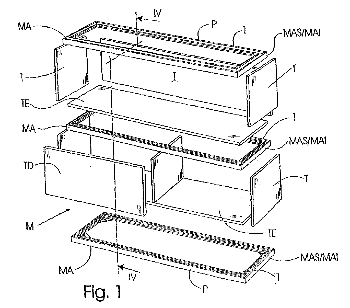
- Fig. 1 is an exploded view of the furniture item structure of the present invention illustrating two levels.
- Fig. 2 is an exploded and fragmentary view illustrating the fragmentary main hollow section making up the furniture item structure frame defining the two upperly and inferiorly opposite channel grooves and the intermediary, hollow ledge, said hollow section forming two consecutive sides of the frame, the additional channel making up the sliding door rest or leveller, the L-shaped angle plate to be provided as a joining element at each corner of each frame, said L-shaped angle plate being made to fit into the corresponding hollow ledges, and the right-angled triangular plate being provided to be inferiorly fitted at each corner of the structure.
- Fig. 3 is a perspective view illustrating the assembly of the furniture item structure being directly carried out by the labourer without using tools in the process.
- Fig. 4 is a fragmentary, sectional view as seen in a side elevation of the furniture item structure showing two shelf levels.
- Fig. 5 is a fragmentary plan-view showing the L-shaped angle plate being fitted at a corner into the main hollow sections of the consecutive sides, and the lower right-angled triangular plate being fitted thereto.
- Fig. 6 is a front perspective view of an embodiment of the assembled furniture item structure.
- According to the drawings the furniture item structure for forming cupboards, bookcases and the like being the object of the present invention as generally designated at -M- is made up of a superimposed succession of shelves being designated at -E- going from the floor or lowest one -EI- up to the one -ES- being located at the highest level.
- The furniture item structure -M- of the invention comprises a plurality of frames -MA-, each shelf level - EI- to -ES- comprising an upper frame -MAS- and a lower frame -MAI-. Said frames -MA- are provided with opposite channel grooves namely being an upper channel groove -1- and a lower channel groove -2- between which the boards - T- making up the sides and the back are made to fit, and with an intermediary, hollow ledge -3- extending towards the inside of the frame -MA-, the board -TE- making up the lower and/or upper shelf coming to rest and fit upon said intermediary, hollow ledge.
- According to the invention said frames -MA- are made up of a main hollow section -P-, this latter being an extruded section making up the sides of the frame -MA-, these latter being for such a purpose secured to each other at the corners by means of L-shaped angle plates - 4-.
- As shown in the Figures, especially in Figs. 2 and 4, the aforementioned main hollow sections -P- have a main portion having an essentially H-shaped configuration laterally extending into the intermediary, hollow ledge - 3-, said H-shaped main portion defining two opposite channel grooves namely being an upper channel groove -1- and a lower channel groove -2- making up the mutually facing channel grooves into which the upper and lower boards -T- making up the sides or the back are made to fit, said intermediary, hollow ledge -3- being innerly arranged in the frame -MA- when carrying out the assembly of this latter (see especially Figs. 4 and 5). The upper surface -3A- of the ledge -3- makes up the actual ledge upon which the board -TE- making up the slab of the ledge -E- will fit and rest, the sides of the L-shaped angle plates -4- joining the sections -P- of two adjacent sides at the corresponding corners being introduced into the hollow space -3B- of said intermediary, hollow ledge (see Figs. 2 and 5).
- As illustrated in the drawings, each of the opposite channel grooves -1-, -2- of the main H-shaped portion of the main hollow shape -P- comprises two mutually facing guides -5-, -5- into which an essentially U-shaped channel -6- being provided with longitudinal flanges externally projecting from the branches can be fitted, said additional channel -6- being fit to be fitted into the mutually facing guides -5-, -5- of the upper channel groove -1- of the H-shaped portion in two positions namely being a first, inverted position in which the middle portion of the additional channel -6- is upperly positioned and flush with the edges of said channel groove -1- and of the board -TE- making up the slab of the shelf -E-, see Fig. 4 illustrating said additional channel -6- in an inverted position at the top of the upper shelf -ES-, and a second, normal position in which said middle portion is inferiorly positioned as shown in the same Fig 4 at the lower frame of the lower shelf, said middle portion in this latter position acting as a guide for a board making up a sliding door -PD- of the shelf in question.
- The furniture item structure -M- of the invention comprises right-angled, essentially triangular plates -7- that are to be inferiorly secured at a respective corner of the lower frame -MA- being adjacent to the floor, in the space being defined at the lower surface of the intermediary, hollow ledge -3- (see the lower portion of Fig. 4 and Fig. 5). Said right-angled triangular plates - 7- additionally allow to inferiorly secure resting and/or rolling means. As illustrated in the Figures, the intermediary, hollow ledge -3-, the L-shaped angle plate -4- and the right-angled triangular plate -7- are provided with respective coincident holes -8- for their fastening by means of screws -9- or the like. The right-angled triangular plate does besides have an orifice -10- allowing to secure a rest or wheel.
- In order to improve the direct fitting of the components in a mutually fitting connection thus enhancing the solidity of the structure, the hollow section -P- can incorporate pins -11- projecting in the opposite channel grooves -1-, -2-, said pins being made to fit into respective blind holes -12- having been drilled in the edges of the side and back boards -T- of the shelves -ES-, the cooperation between said pins -11- and blind holes -12- thus bringing about an improvement of both the mutual connection of the different components and the stability of the whole assembly.
- The present invention provides for the shelf levels -ES- to have the same height or different heights, the boards -T- hence having the corresponding height. The furniture item structure can likewise have any desired height as resulting from the number of shelf levels and/or from the height of these latter.
- It is finally to be pointed out that the furniture item structure of the present invention can be easily and directly assembled/disassembled by the user, i.e. without requiring the use of tools, since the different components of the structure are fit to be simply fitted to each other in a mutually fitting connection.
- The material of the frames -MA- making up the horizontal structures defining the shelves of the piece of furniture can be any convenient material, although said frames are preferably made of extruded metal, but said material could as well be a plastics material based on a hard, tough, nonbrittle resin.
- The back and side boards -T- and those making up the slab -TE- of each shelf level can be of any convenient material, and hence they can even be particle boards having their surfaces coated with respective claddings.
- It has to be borne in mind that regardless of the preferred furniture item embodiment having been represented in the drawings the furniture item structure being the object of the present invention allows the very user to form and hence assemble/disassemble any type of furniture item, whether a cupboard, a bookcase or any other piece of furniture as desired by the user, all this with no need to use tools in the process.
Claims (7)
- A furniture item structure for forming cupboards, bookcases and the like comprising a number of shelves being possibly provided with partitions, doors, drawers, files, show windows and the like; characterised in that each shelf and/or equivalent level comprises an upper frame and a lower frame being provided with mutually facing channel grooves between which those boards are made to fit which make up the sides and the back, and with an inner ledge upon which the board making up the lower and/or upper shelf comes to rest and fit, the whole assembly being delimited by an upper end frame and a lower end frame.
- A furniture item structure as per claim 1, characterised in that said frames are made up of an extruded hollow section making up the sides of the structure, said sides being secured to each other at the corners by means of angle plates.
- A furniture item structure as per claim 2, characterised in that said hollow sections have a main portion having an essentially H-shaped configuration and laterally extending into an intermediary, hollow ledge, said main H-shaped portion defining two upperly and inferiorly opposite channel grooves making up the mutually facing channel grooves into which the upper and lower boards of each shelf level are fitted, said intermediary, hollow ledge being innerly arranged in the frame when assembling this latter, the upper surface of said intermediary, hollow ledge making up the actual ledge upon which the board making up the shelf will fit and rest, the sides of the L-shaped angle plates joining the sections of two adjacent sides at the corresponding corners being introduced into the hollow space of said intermediary, hollow ledge.
- A furniture item structure as per claim 3, characterised in that each of the opposite channel grooves of the main H-shaped portion of the hollow section comprises two mutually facing guides into which an essentially U-shaped channel being provided with longitudinal flanges externally projecting from the branches can be fitted, said channel being fit to be fitted into the mutually facing guides of the upper channel groove of the H-shaped portion in two positions namely being a first, inverted position in which the middle portion of the channel is upperly positioned and flush with the edges of said channel groove and of the board making up the shelf, and a second, normal position in which said middle portion is inferiorly positioned and acts as a guide for a board making up a sliding door of the shelf in question.
- A furniture item structure as per claim 3, characterised in that it comprises right-angled, essentially triangular plates that are to be inferiorly secured at a respective corner of the lower frame being adjacent to the floor, in the space being defined at the lower surface of the intermediary, hollow ledge of the hollow section, said right-angled triangular plates allowing to inferiorly secure resting and/or rolling means.
- A furniture item structure as per claim 3, characterised in that the hollow section possibly incorporates pins projecting in the opposite channel grooves of the H-shaped portion, said pins being made to fit into respective blind holes having been drilled in the side and back boards of the shelves, the cooperation between said pins and blind holes thus bringing about an improvement of both the mutual connection of the different components and the stability of the whole assembly.
- A furniture item structure as per the preceding claims, characterised in that the shelf and/or equivalent levels have the same and/or a different height, the back and side boards and/or the partitions between the upper frame and the lower frame of the respective shelf hence having the corresponding height; in that the structure comprises the appropriate number of shelf and/or equivalent levels and thus allows to increase/reduce the number of levels and hence the height by adding/removing levels as desired; and in that the parts making up the structure are fit to be directly assembled together/disassembled by the user by simply fitting them to each other in a mutually fitting connection.
Applications Claiming Priority (2)
| Application Number | Priority Date | Filing Date | Title |
|---|---|---|---|
| ES200301499U ES1055226Y (en) | 2003-06-19 | 2003-06-19 | FURNITURE STRUCTURE FOR TRAINING OF CABINETS, BOOKS AND SIMILAR. |
| PCT/ES2004/000279 WO2004112540A1 (en) | 2003-06-19 | 2004-06-17 | Furniture structure for the production of cabinets, bookcases and similar |
Publications (2)
| Publication Number | Publication Date |
|---|---|
| EP1647205A1 true EP1647205A1 (en) | 2006-04-19 |
| EP1647205B1 EP1647205B1 (en) | 2011-12-28 |
Family
ID=29763113
Family Applications (1)
| Application Number | Title | Priority Date | Filing Date |
|---|---|---|---|
| EP04736982A Expired - Lifetime EP1647205B1 (en) | 2003-06-19 | 2004-06-17 | Furniture structure for the production of cabinets, bookcases and similar |
Country Status (4)
| Country | Link |
|---|---|
| EP (1) | EP1647205B1 (en) |
| AT (1) | ATE538681T1 (en) |
| ES (2) | ES1055226Y (en) |
| WO (1) | WO2004112540A1 (en) |
Cited By (10)
| Publication number | Priority date | Publication date | Assignee | Title |
|---|---|---|---|---|
| CN103169280A (en) * | 2013-03-12 | 2013-06-26 | 苏州科技学院 | Prefabricated wall-in type modular furniture storage system |
| US8534752B2 (en) | 2010-06-02 | 2013-09-17 | Steelcase Inc. | Reconfigurable table assemblies |
| US8667908B2 (en) | 2010-06-02 | 2014-03-11 | Steelcase Inc. | Frame type table assemblies |
| GB2507115A (en) * | 2012-10-22 | 2014-04-23 | Fc Brown Steel Equipment Ltd | A carcase for storage furniture with struts connecting side panels |
| US9185974B2 (en) | 2010-06-02 | 2015-11-17 | Steelcase Inc. | Frame type workstation configurations |
| US9210999B2 (en) | 2010-06-02 | 2015-12-15 | Steelcase Inc. | Frame type table assemblies |
| US10039374B2 (en) | 2016-05-13 | 2018-08-07 | Steelcase Inc. | Multi-tiered workstation assembly |
| US10517392B2 (en) | 2016-05-13 | 2019-12-31 | Steelcase Inc. | Multi-tiered workstation assembly |
| US10935063B2 (en) | 2008-12-17 | 2021-03-02 | Unilin Bv | Composed element, multi-layered board and panel-shaped element for forming this composed element |
| US12376677B1 (en) | 2012-10-10 | 2025-08-05 | Steelcase Inc. | Ergonomic seating system, tilt-lock control and remote powering method and apparatus |
Families Citing this family (2)
| Publication number | Priority date | Publication date | Assignee | Title |
|---|---|---|---|---|
| CA2796588C (en) | 2010-06-03 | 2019-03-19 | Unilin, Bvba | Composed element and corner connection applied herewith. |
| BE1020044A5 (en) | 2011-06-29 | 2013-04-02 | Unilin Bvba | TRAY, TRAY CONSTRUCTION AND METHOD FOR MANUFACTURING A TRAY. |
Family Cites Families (5)
| Publication number | Priority date | Publication date | Assignee | Title |
|---|---|---|---|---|
| US3285444A (en) * | 1965-03-01 | 1966-11-15 | Beautiline Ltd | Extruded frame member |
| GB1281521A (en) * | 1968-08-29 | 1972-07-12 | W G Cox & Son Ltd | Sliding door construction and sections for use therein |
| DE7733462U1 (en) * | 1977-10-29 | 1978-03-23 | Eubel, Karl, 8621 Mitwitz | FURNITURE, IN PARTICULAR CABINET OR SHELVING |
| US5524977A (en) * | 1995-02-24 | 1996-06-11 | Orawski; Walter | Security display case |
| GB2354426B (en) * | 1999-09-25 | 2004-03-24 | Netherfield Visual Ltd | Side wall mounting for a showcase |
-
2003
- 2003-06-19 ES ES200301499U patent/ES1055226Y/en not_active Expired - Fee Related
-
2004
- 2004-06-17 ES ES04736982T patent/ES2380197T3/en not_active Expired - Lifetime
- 2004-06-17 EP EP04736982A patent/EP1647205B1/en not_active Expired - Lifetime
- 2004-06-17 AT AT04736982T patent/ATE538681T1/en active
- 2004-06-17 WO PCT/ES2004/000279 patent/WO2004112540A1/en not_active Ceased
Non-Patent Citations (1)
| Title |
|---|
| See references of WO2004112540A1 * |
Cited By (17)
| Publication number | Priority date | Publication date | Assignee | Title |
|---|---|---|---|---|
| US11319977B2 (en) | 2008-12-17 | 2022-05-03 | Flooring Industries Limited, Sarl | Composed element, multi-layered board and panel-shaped element for forming this composed element |
| US10935063B2 (en) | 2008-12-17 | 2021-03-02 | Unilin Bv | Composed element, multi-layered board and panel-shaped element for forming this composed element |
| US8534752B2 (en) | 2010-06-02 | 2013-09-17 | Steelcase Inc. | Reconfigurable table assemblies |
| US8667908B2 (en) | 2010-06-02 | 2014-03-11 | Steelcase Inc. | Frame type table assemblies |
| US8689705B2 (en) | 2010-06-02 | 2014-04-08 | Steelcase, Inc. | Reconfigurable table assemblies |
| US9185974B2 (en) | 2010-06-02 | 2015-11-17 | Steelcase Inc. | Frame type workstation configurations |
| US9210999B2 (en) | 2010-06-02 | 2015-12-15 | Steelcase Inc. | Frame type table assemblies |
| US11930926B2 (en) | 2010-06-02 | 2024-03-19 | Steelcase Inc. | Frame type workstation configurations |
| US11317716B2 (en) | 2010-06-02 | 2022-05-03 | Steelcase Inc. | Frame type workstation configurations |
| US10681980B2 (en) | 2010-06-02 | 2020-06-16 | Steelcase Inc. | Frame type workstation configurations |
| US12616301B1 (en) | 2012-10-10 | 2026-05-05 | Steelcase Inc. | Ergonomic seating system, tilt-lock control and remote powering method and apparatus |
| US12376677B1 (en) | 2012-10-10 | 2025-08-05 | Steelcase Inc. | Ergonomic seating system, tilt-lock control and remote powering method and apparatus |
| GB2507115A (en) * | 2012-10-22 | 2014-04-23 | Fc Brown Steel Equipment Ltd | A carcase for storage furniture with struts connecting side panels |
| CN103169280B (en) * | 2013-03-12 | 2015-06-03 | 苏州科技学院 | Prefabricated wall-in type modular furniture storage system |
| CN103169280A (en) * | 2013-03-12 | 2013-06-26 | 苏州科技学院 | Prefabricated wall-in type modular furniture storage system |
| US10517392B2 (en) | 2016-05-13 | 2019-12-31 | Steelcase Inc. | Multi-tiered workstation assembly |
| US10039374B2 (en) | 2016-05-13 | 2018-08-07 | Steelcase Inc. | Multi-tiered workstation assembly |
Also Published As
| Publication number | Publication date |
|---|---|
| ATE538681T1 (en) | 2012-01-15 |
| ES1055226Y (en) | 2004-02-16 |
| EP1647205B1 (en) | 2011-12-28 |
| WO2004112540A1 (en) | 2004-12-29 |
| ES1055226U (en) | 2003-11-01 |
| ES2380197T3 (en) | 2012-05-09 |
Similar Documents
| Publication | Publication Date | Title |
|---|---|---|
| US4171150A (en) | Mountable storage furniture | |
| US6681705B2 (en) | Support structure and method of assembly thereof | |
| US9826828B1 (en) | Cabinet assembly system utilizing cooperating grooved components | |
| US10136726B2 (en) | Modular cabinet with hidden clamping system | |
| EP0298433B1 (en) | Partition wall, particularly for offices | |
| US3846002A (en) | Building unit for furniture | |
| EP1647205B1 (en) | Furniture structure for the production of cabinets, bookcases and similar | |
| US3717396A (en) | Modular shell cabinet structure | |
| US20080116776A1 (en) | Quick Assembly Adjustable Shelf and Drawer System | |
| US3178244A (en) | Modular enclosure | |
| GB2527343A (en) | Expandable storage structure | |
| US10648497B2 (en) | Connectable box carcass framework members | |
| US3429631A (en) | Home-assembled furniture kit | |
| US9661922B2 (en) | Outdoor modular frame system | |
| US20180360210A1 (en) | Box Carcass Assembly Method | |
| US20070252494A1 (en) | Method and apparatus for installing a sliding drawer within a cabinet | |
| EP1953395A1 (en) | A method of assembling sandwich panels in an angular relationship, and structures made by the method | |
| WO2000074524A3 (en) | Selectively variable modular space system with shelving and enclosures | |
| US20080067906A1 (en) | Modular components for building structures | |
| US4447096A (en) | Cabinet assembly system | |
| EP3822447B1 (en) | Structure for highly versatile sliding architectural elements | |
| EP3192396B1 (en) | Table top | |
| US3515451A (en) | Modular knock-down cabinet | |
| KR102598229B1 (en) | A prefabricated bookshelf | |
| US20190150613A1 (en) | Modular counter and cabinet system |
Legal Events
| Date | Code | Title | Description |
|---|---|---|---|
| PUAI | Public reference made under article 153(3) epc to a published international application that has entered the european phase |
Free format text: ORIGINAL CODE: 0009012 |
|
| 17P | Request for examination filed |
Effective date: 20051229 |
|
| AK | Designated contracting states |
Kind code of ref document: A1 Designated state(s): AT BE BG CH CY CZ DE DK EE ES FI FR GB GR HU IE IT LI LU MC NL PL PT RO SE SI SK TR |
|
| DAX | Request for extension of the european patent (deleted) | ||
| 17Q | First examination report despatched |
Effective date: 20071119 |
|
| GRAP | Despatch of communication of intention to grant a patent |
Free format text: ORIGINAL CODE: EPIDOSNIGR1 |
|
| GRAS | Grant fee paid |
Free format text: ORIGINAL CODE: EPIDOSNIGR3 |
|
| GRAA | (expected) grant |
Free format text: ORIGINAL CODE: 0009210 |
|
| AK | Designated contracting states |
Kind code of ref document: B1 Designated state(s): AT BE BG CH CY CZ DE DK EE ES FI FR GB GR HU IE IT LI LU MC NL PL PT RO SE SI SK TR |
|
| REG | Reference to a national code |
Ref country code: GB Ref legal event code: FG4D |
|
| REG | Reference to a national code |
Ref country code: CH Ref legal event code: EP |
|
| REG | Reference to a national code |
Ref country code: AT Ref legal event code: REF Ref document number: 538681 Country of ref document: AT Kind code of ref document: T Effective date: 20120115 |
|
| REG | Reference to a national code |
Ref country code: IE Ref legal event code: FG4D |
|
| REG | Reference to a national code |
Ref country code: DE Ref legal event code: R096 Ref document number: 602004035868 Country of ref document: DE Effective date: 20120322 |
|
| REG | Reference to a national code |
Ref country code: NL Ref legal event code: VDEP Effective date: 20111228 |
|
| REG | Reference to a national code |
Ref country code: ES Ref legal event code: FG2A Ref document number: 2380197 Country of ref document: ES Kind code of ref document: T3 Effective date: 20120509 |
|
| PG25 | Lapsed in a contracting state [announced via postgrant information from national office to epo] |
Ref country code: GR Free format text: LAPSE BECAUSE OF FAILURE TO SUBMIT A TRANSLATION OF THE DESCRIPTION OR TO PAY THE FEE WITHIN THE PRESCRIBED TIME-LIMIT Effective date: 20120329 Ref country code: SI Free format text: LAPSE BECAUSE OF FAILURE TO SUBMIT A TRANSLATION OF THE DESCRIPTION OR TO PAY THE FEE WITHIN THE PRESCRIBED TIME-LIMIT Effective date: 20111228 Ref country code: SE Free format text: LAPSE BECAUSE OF FAILURE TO SUBMIT A TRANSLATION OF THE DESCRIPTION OR TO PAY THE FEE WITHIN THE PRESCRIBED TIME-LIMIT Effective date: 20111228 |
|
| PG25 | Lapsed in a contracting state [announced via postgrant information from national office to epo] |
Ref country code: BE Free format text: LAPSE BECAUSE OF FAILURE TO SUBMIT A TRANSLATION OF THE DESCRIPTION OR TO PAY THE FEE WITHIN THE PRESCRIBED TIME-LIMIT Effective date: 20111228 Ref country code: CY Free format text: LAPSE BECAUSE OF FAILURE TO SUBMIT A TRANSLATION OF THE DESCRIPTION OR TO PAY THE FEE WITHIN THE PRESCRIBED TIME-LIMIT Effective date: 20111228 |
|
| PG25 | Lapsed in a contracting state [announced via postgrant information from national office to epo] |
Ref country code: CZ Free format text: LAPSE BECAUSE OF FAILURE TO SUBMIT A TRANSLATION OF THE DESCRIPTION OR TO PAY THE FEE WITHIN THE PRESCRIBED TIME-LIMIT Effective date: 20111228 Ref country code: EE Free format text: LAPSE BECAUSE OF FAILURE TO SUBMIT A TRANSLATION OF THE DESCRIPTION OR TO PAY THE FEE WITHIN THE PRESCRIBED TIME-LIMIT Effective date: 20111228 Ref country code: SK Free format text: LAPSE BECAUSE OF FAILURE TO SUBMIT A TRANSLATION OF THE DESCRIPTION OR TO PAY THE FEE WITHIN THE PRESCRIBED TIME-LIMIT Effective date: 20111228 Ref country code: NL Free format text: LAPSE BECAUSE OF FAILURE TO SUBMIT A TRANSLATION OF THE DESCRIPTION OR TO PAY THE FEE WITHIN THE PRESCRIBED TIME-LIMIT Effective date: 20111228 Ref country code: BG Free format text: LAPSE BECAUSE OF FAILURE TO SUBMIT A TRANSLATION OF THE DESCRIPTION OR TO PAY THE FEE WITHIN THE PRESCRIBED TIME-LIMIT Effective date: 20120328 |
|
| PG25 | Lapsed in a contracting state [announced via postgrant information from national office to epo] |
Ref country code: PT Free format text: LAPSE BECAUSE OF FAILURE TO SUBMIT A TRANSLATION OF THE DESCRIPTION OR TO PAY THE FEE WITHIN THE PRESCRIBED TIME-LIMIT Effective date: 20120430 Ref country code: RO Free format text: LAPSE BECAUSE OF FAILURE TO SUBMIT A TRANSLATION OF THE DESCRIPTION OR TO PAY THE FEE WITHIN THE PRESCRIBED TIME-LIMIT Effective date: 20111228 Ref country code: PL Free format text: LAPSE BECAUSE OF FAILURE TO SUBMIT A TRANSLATION OF THE DESCRIPTION OR TO PAY THE FEE WITHIN THE PRESCRIBED TIME-LIMIT Effective date: 20111228 |
|
| REG | Reference to a national code |
Ref country code: AT Ref legal event code: MK05 Ref document number: 538681 Country of ref document: AT Kind code of ref document: T Effective date: 20111228 |
|
| PG25 | Lapsed in a contracting state [announced via postgrant information from national office to epo] |
Ref country code: DK Free format text: LAPSE BECAUSE OF FAILURE TO SUBMIT A TRANSLATION OF THE DESCRIPTION OR TO PAY THE FEE WITHIN THE PRESCRIBED TIME-LIMIT Effective date: 20111228 |
|
| PLBE | No opposition filed within time limit |
Free format text: ORIGINAL CODE: 0009261 |
|
| STAA | Information on the status of an ep patent application or granted ep patent |
Free format text: STATUS: NO OPPOSITION FILED WITHIN TIME LIMIT |
|
| PG25 | Lapsed in a contracting state [announced via postgrant information from national office to epo] |
Ref country code: IT Free format text: LAPSE BECAUSE OF FAILURE TO SUBMIT A TRANSLATION OF THE DESCRIPTION OR TO PAY THE FEE WITHIN THE PRESCRIBED TIME-LIMIT Effective date: 20111228 |
|
| REG | Reference to a national code |
Ref country code: DE Ref legal event code: R231 Ref document number: 602004035868 Country of ref document: DE |
|
| 26N | No opposition filed |
Effective date: 20121001 |
|
| PGFP | Annual fee paid to national office [announced via postgrant information from national office to epo] |
Ref country code: ES Payment date: 20120615 Year of fee payment: 9 |
|
| REG | Reference to a national code |
Ref country code: DE Ref legal event code: R097 Ref document number: 602004035868 Country of ref document: DE Effective date: 20121001 |
|
| PG25 | Lapsed in a contracting state [announced via postgrant information from national office to epo] |
Ref country code: MC Free format text: LAPSE BECAUSE OF NON-PAYMENT OF DUE FEES Effective date: 20120630 Ref country code: AT Free format text: LAPSE BECAUSE OF FAILURE TO SUBMIT A TRANSLATION OF THE DESCRIPTION OR TO PAY THE FEE WITHIN THE PRESCRIBED TIME-LIMIT Effective date: 20111228 |
|
| REG | Reference to a national code |
Ref country code: CH Ref legal event code: PL |
|
| REG | Reference to a national code |
Ref country code: CH Ref legal event code: PL |
|
| GBPC | Gb: european patent ceased through non-payment of renewal fee |
Effective date: 20120617 |
|
| REG | Reference to a national code |
Ref country code: IE Ref legal event code: MM4A |
|
| REG | Reference to a national code |
Ref country code: FR Ref legal event code: ST Effective date: 20130228 |
|
| PG25 | Lapsed in a contracting state [announced via postgrant information from national office to epo] |
Ref country code: CH Free format text: LAPSE BECAUSE OF NON-PAYMENT OF DUE FEES Effective date: 20120630 Ref country code: GB Free format text: LAPSE BECAUSE OF NON-PAYMENT OF DUE FEES Effective date: 20120617 Ref country code: LI Free format text: LAPSE BECAUSE OF NON-PAYMENT OF DUE FEES Effective date: 20120630 Ref country code: FR Free format text: LAPSE BECAUSE OF NON-PAYMENT OF DUE FEES Effective date: 20120702 Ref country code: IE Free format text: LAPSE BECAUSE OF NON-PAYMENT OF DUE FEES Effective date: 20120617 |
|
| PG25 | Lapsed in a contracting state [announced via postgrant information from national office to epo] |
Ref country code: FI Free format text: LAPSE BECAUSE OF FAILURE TO SUBMIT A TRANSLATION OF THE DESCRIPTION OR TO PAY THE FEE WITHIN THE PRESCRIBED TIME-LIMIT Effective date: 20111228 |
|
| PG25 | Lapsed in a contracting state [announced via postgrant information from national office to epo] |
Ref country code: TR Free format text: LAPSE BECAUSE OF FAILURE TO SUBMIT A TRANSLATION OF THE DESCRIPTION OR TO PAY THE FEE WITHIN THE PRESCRIBED TIME-LIMIT Effective date: 20111228 |
|
| PG25 | Lapsed in a contracting state [announced via postgrant information from national office to epo] |
Ref country code: LU Free format text: LAPSE BECAUSE OF NON-PAYMENT OF DUE FEES Effective date: 20120617 |
|
| REG | Reference to a national code |
Ref country code: ES Ref legal event code: FD2A Effective date: 20140707 |
|
| PG25 | Lapsed in a contracting state [announced via postgrant information from national office to epo] |
Ref country code: HU Free format text: LAPSE BECAUSE OF FAILURE TO SUBMIT A TRANSLATION OF THE DESCRIPTION OR TO PAY THE FEE WITHIN THE PRESCRIBED TIME-LIMIT Effective date: 20040617 |
|
| PG25 | Lapsed in a contracting state [announced via postgrant information from national office to epo] |
Ref country code: DE Free format text: LAPSE BECAUSE OF THE APPLICANT RENOUNCES Effective date: 20121204 |
|
| PG25 | Lapsed in a contracting state [announced via postgrant information from national office to epo] |
Ref country code: ES Free format text: LAPSE BECAUSE OF NON-PAYMENT OF DUE FEES Effective date: 20130618 |