EP1646987B1 - Security system - Google Patents
Security system Download PDFInfo
- Publication number
- EP1646987B1 EP1646987B1 EP04743355A EP04743355A EP1646987B1 EP 1646987 B1 EP1646987 B1 EP 1646987B1 EP 04743355 A EP04743355 A EP 04743355A EP 04743355 A EP04743355 A EP 04743355A EP 1646987 B1 EP1646987 B1 EP 1646987B1
- Authority
- EP
- European Patent Office
- Prior art keywords
- vehicle
- transceiver means
- signal
- transceiver
- cpu
- Prior art date
- Legal status (The legal status is an assumption and is not a legal conclusion. Google has not performed a legal analysis and makes no representation as to the accuracy of the status listed.)
- Expired - Lifetime
Links
- 230000004044 response Effects 0.000 claims abstract description 11
- 230000033001 locomotion Effects 0.000 claims description 16
- 230000000007 visual effect Effects 0.000 claims description 3
- 230000009471 action Effects 0.000 description 4
- 238000013459 approach Methods 0.000 description 2
- 230000005540 biological transmission Effects 0.000 description 2
- 230000006872 improvement Effects 0.000 description 2
- 238000010276 construction Methods 0.000 description 1
- 230000001351 cycling effect Effects 0.000 description 1
- 230000000694 effects Effects 0.000 description 1
- 238000000034 method Methods 0.000 description 1
- 238000012986 modification Methods 0.000 description 1
- 230000004048 modification Effects 0.000 description 1
- 230000000737 periodic effect Effects 0.000 description 1
- 230000008092 positive effect Effects 0.000 description 1
- 230000003068 static effect Effects 0.000 description 1
Images
Classifications
-
- B—PERFORMING OPERATIONS; TRANSPORTING
- B60—VEHICLES IN GENERAL
- B60R—VEHICLES, VEHICLE FITTINGS, OR VEHICLE PARTS, NOT OTHERWISE PROVIDED FOR
- B60R25/00—Fittings or systems for preventing or indicating unauthorised use or theft of vehicles
- B60R25/20—Means to switch the anti-theft system on or off
- B60R25/24—Means to switch the anti-theft system on or off using electronic identifiers containing a code not memorised by the user
-
- G—PHYSICS
- G07—CHECKING-DEVICES
- G07C—TIME OR ATTENDANCE REGISTERS; REGISTERING OR INDICATING THE WORKING OF MACHINES; GENERATING RANDOM NUMBERS; VOTING OR LOTTERY APPARATUS; ARRANGEMENTS, SYSTEMS OR APPARATUS FOR CHECKING NOT PROVIDED FOR ELSEWHERE
- G07C9/00—Individual registration on entry or exit
- G07C9/00174—Electronically operated locks; Circuits therefor; Nonmechanical keys therefor, e.g. passive or active electrical keys or other data carriers without mechanical keys
- G07C9/00309—Electronically operated locks; Circuits therefor; Nonmechanical keys therefor, e.g. passive or active electrical keys or other data carriers without mechanical keys operated with bidirectional data transmission between data carrier and locks
-
- G—PHYSICS
- G07—CHECKING-DEVICES
- G07C—TIME OR ATTENDANCE REGISTERS; REGISTERING OR INDICATING THE WORKING OF MACHINES; GENERATING RANDOM NUMBERS; VOTING OR LOTTERY APPARATUS; ARRANGEMENTS, SYSTEMS OR APPARATUS FOR CHECKING NOT PROVIDED FOR ELSEWHERE
- G07C2209/00—Indexing scheme relating to groups G07C9/00 - G07C9/38
- G07C2209/60—Indexing scheme relating to groups G07C9/00174 - G07C9/00944
- G07C2209/63—Comprising locating means for detecting the position of the data carrier, i.e. within the vehicle or within a certain distance from the vehicle
Definitions
- the present invention relates to a security system and particularly, but not exclusively, to a security system for a vehicle such as an automobile. More specifically, the invention concerns an improvement to so-called "passive entry” or “keyless entry” vehicle locking systems.
- Improvements in electronics systems led to the introduction of remote locking systems involving a transmitter unit in a key fob held by the vehicle user and a receiver unit located within the vehicle.
- the transmitter unit is arranged to transmit a LOCK/UNLOCK signal to the receiver unit in response to the user actuating a button on the key fob.
- a control unit in the vehicle On receipt of the LOCK/UNLOCK signal by the receiver unit, a control unit in the vehicle causes the vehicle doors to unlock or lock, depending on the current locked/unlocked state of the vehicle.
- the key can be used to lock/unlock the vehicle doors in the conventional manner and is, in general, required to switch on the ignition.
- VTU vehicle transceiver unit
- While passive entry systems are generally considered to provide a number of advantages to the user, particularly in that the user is not required to manually operate the token, or even to be holding the token in hand, in order to unlock the vehicle doors, the applicant company has identified a significant disadvantage of the system relating to vehicle security.
- the transceiver unit in the vehicle uses only the detected distance of the token from the vehicle and not the exact disposition or location of the token, such as whether it is in the user's pocket or bag or, indeed, in the possession of the user at all. Furthermore, there is no positive action required on the part of the user in respect of the token. The only action required by the user in order to unlock the vehicle doors is to press a button on the vehicle door itself. This activates the vehicle transceiver unit which determines whether the distance between the token and the vehicle is less than a predetermined threshold distance, the vehicle transceiver unit sends a signal to the control unit for the vehicle's central locking system which then unlocks the vehicle doors.
- the thief may then be able to switch on the ignition and possibly start the vehicle by "hot wiring" or other methods. Even if the thief is unable to start the vehicle, once inside the vehicle could be vandalised or possessions stolen.
- EP 1006249 discloses a passive entry system for a vehicle according to the preamble of claims 1 and 2.
- a passive entry system according to claim 1.
- a passive entry system according to claim 2.
- the passive entry system 10 includes a vehicle transceiver unit (VTU) 12 comprising a central processing unit (CPU) 14, connected to a transmitter 16 and to a receiver 18.
- VTU vehicle transceiver unit
- CPU central processing unit
- the transmitter 16 is connected to a plurality of antennas A1 - A3 which serve to transmit electromagnetic signals generated by the transmitter 16.
- the receiver 18 is connected to an antenna A4 which serves to receive electromagnetic signals received by the receiver 18, as described below.
- switches S1 - S3 are connected to the CPU 14 within the VTU 12, each switch being located on a respective door of the vehicle.
- Switch S1 for example, is located on the driver's door of the vehicle whilst switch S2 is located on the passenger or “assist” door and switch S3 on the back door of the vehicle.
- the CPU 14 in the VTU 12 is also connected to a lock actuator control unit 20 which communicates with a plurality of lock actuators L1 - L4 for locking and unlocking selected doors of the vehicle.
- FIG. 2 this illustrates a known form of user transceiver unit 30 referred to hereafter as a "token”.
- the token 30 takes the form of a relatively small, plastic housing within which is contained a first antenna arrangement 32, a receiver unit 34, an central processing unit (CPU) 36, a transmitter unit 38 and a transmitting antenna system 40.
- CPU central processing unit
- transmitter unit 38 a transmitting antenna system 40.
- transmitting antenna system 40 The electronic composition of such units will be well understood by the skilled person with reference to the function thereof as indicated below and are not, therefore, described in detail herein.
- the system remains dormant. No signals are transmitted either by the VTU 12 or by the token 30.
- the vehicle doors (not shown) are locked.
- the user approaches the vehicle carrying the token 30 either in hand or in a pocket or bag. There is no requirement for the user to have manual access to the token since the system is passive and manual operation of the token is not necessary.
- the user To open, for example, the driver's door, the user approaches the door and presses the switch S1 located on the door itself. Pressing of the switch S1 causes an electrical current to flow therethrough, which is detected by the CPU 14.
- the CPU 14 then generates a command signal in the form of a 48-bit digital signal which includes a unique 8-bit identifier portion.
- the command signal is applied to the transmitter unit 16 for transmission.
- the transmitter unit 16 is arranged to modulate the command signal with a low frequency (LF) carrier signal at approximately 125kHz, amplify it and then transmit it via one or more of the antennas A1 - A3.
- LF low frequency
- the command signal is transmitted via the antenna corresponding to the switch pressed by the user.
- the antennas A1 - A3 are arranged such that the range of the transmitted command signal, hereafter termed the threshold range, does not exceed approximately 2m from the vehicle.
- the reason for this range restriction is that it is desired to prevent a situation whereby a thief can unlock the vehicle doors by pressing the relevant switch S1 - S3 on the vehicle whilst the owner, who is in possession of the token, is too far away to take preventative action.
- the CPU 14 After transmission of the command signal, the CPU 14 applies a predetermined algorithm to the identifier portion of the command signal to produce a unique reference value for reasons which are described below.
- the signal is received by the receiver unit 34 in the token 30 via the first antenna arrangement 32.
- the receiver unit 34 applies the command signal to the CPU 36 which applies the predetermined algorithm to the identifier portion of the command signal to produce a unique token value.
- the token value is then modulated by the transmitter unit 38 with a carrier signal having a frequency of approximately 432MHz, amplified and is then transmitted back to the vehicle.
- the transmitted signal representing the token value is received by the receiver unit 18 within the VTU 12.
- the receiver unit 18 demodulates the signal to extract the token value and applies the token value to the CPU 14.
- the CPU 14 compares the token value with the reference value generated previously. If the token value matches the reference value, then the CPU 14 sends an UNLOCK signal to the lock actuator controller 20 to control the relevant lock or locks L1 - L4 thereby to unlock the relevant vehicle door. In some systems, pressing the switch twice in quick succession unlocks two or more of the vehicle doors.
- the system is such that the signal sent by the CPU to the lock actuator controller toggles between LOCK and UNLOCK, depending on the initial condition of the door, i.e. whether the door was locked or unlocked when the signal is sent.
- a disadvantage of passive entry systems is that, provided the token 30 is within the threshold range of the command signal from the VTU 12, almost irrespective of its actual location, it may be possible for an unauthorised person, such as a thief, to gain access to the vehicle simply by operating one of the switches on the vehicle doors. Once access to the vehicle is gained, the vehicle could be "hot wired" to start the engine, the interior could be vandalised or belongings in the vehicle could be stolen.
- Such a situation might arise, for example, if the vehicle is parked in close proximity to the owner's house. In this case, the distance between the vehicle and the token within the house might be less than the threshold range of the command signal, in which case a potential thief merely has to operate one of the door switches S1 - S3. As described above, the VTU 12 will transmit the command signal to the token 30 which will respond with the correct code or token value, regardless of the fact that the token itself 30 is not in the possession of the thief, thereby permitting the vehicle door to be opened.
- FIGs 3 and 4 together illustrate a first form of passive entry system according to the invention which aims to address this drawback.
- the system of the invention comprises all of the features of the prior art system described with reference to Figure 1 .
- the VTU 12 is additionally provided with a timer 60 connected to the CPU 14.
- the token 30 includes all of the features of the token described with reference to Figure 2 but additionally includes means 42, such as a transducer, connected to the CPU 36, for generating a tactile, visual or audible signal to the user, as described below.
- means 42 such as a transducer
- the timer 60 begins to count down a predetermined time period.
- the time period may be selected as desired but in the preferred embodiment is at least five minutes.
- the CPU 14 periodically or continuously generates an interrogation signal, similar in form to the command signal, and transmits it via the transmitter 16 and antennas A1 - A3 as described above.
- the interrogation signal is received by the token's receiver unit 34 and encoded with the encryption algorithm by the CPU 36.
- the transmitter unit 38 then transmits the encrypted interrogation signal back to the VTU whereby it is received by the receiver unit 18.
- This periodic or continuous scanning function is to determine whether the token has remained within the threshold range of the VTU 12 after the vehicle is locked.
- the CPU 14 If the receiver unit 18 in the VTU 12 is still receiving a reply signal from the token in response to the scanning function after the countdown time on the timer 60 reaches zero, then the CPU 14 generates an alert signal which is applied to the transmitter unit 16, modulated and then transmitted to the token 30 via the antennas A1 - A3.
- the receiver unit 34 in the token receives the alert signal from the VTU 12 and applies it to the CPU 36.
- the CPU 36 controls the transducer 42 to generate a tactile, visual or audible signal (depending on the nature of the transducer provided) to the user.
- the transducer may comprise a buzzer or siren to generate an audible signal to the user, or may comprise an LED or other device for emitting a visible alert signal.
- the purpose of the signal is to advise the user that the token is still within range of the vehicle and the security risk that this presents. The user is then free to relocate the token in a position in which it is outside the threshold range of the vehicle.
- the system is provided with a means for selectively disconnecting or deactivating one or more of the antennas A1 - A3 in response to the reply signal from the token still being received by the receiver unit 18 when the time period on the timer 60 expires.
- This means may be provided by a function in the CPU 14 or the transmitter 16 which selects which of the antennas A1 - A3 the alert signal is transmitted via.
- means may be provided for mechanically or electronically disconnecting the relevant antenna or antennas A1 - A3 from the transmitter 16.
- Such means may comprise mechanical switches or contacts, or electronic switches or circuits such as transistors, in a manner which will be well understood by the skilled person.
- the CPU 14 is able to determine which of the antennas A1 - A3 is within range of the token and thereby to disconnect or deactivate that antenna. This is achieved by "cycling" the antennas, i.e. transmitting the interrogation signal via each antenna A 1 - A3 individually in sequence and waiting for the reply signal from the token. When the reply signal is received, the CPU 14 identifies which antenna the interrogation signal was transmitted via and then disconnects or deactivates that antenna as desired.
- the system is arranged to deactivate the passive entry function after the countdown time on the timer 60 reaches zero.
- This can be achieved in a number of ways. For example, when the timer reaches zero and the token 30 is determined to be still in range of the vehicle as described above, the CPU initiates a routine whereby the UNLOCK signal is no longer generated when any of the door switches S1 - S3 is operated. Since the UNLOCK signal is no longer applied to the lock actuator control unit 20, the vehicle doors will not be unlocked even if the token 30 is in range of the vehicle.
- the door switches may be deactivated, for example by the CPU 14 no longer generating the command signal when any of the door switches S1 - S3 are operated, or through the switches being mechanically or electronically disconnected from the VTU 12.
- the CPU 14 ignores this action and does not generate the command signal or the action is not communicated to the CPU owing to the disconnected status of the switches.
- the VTU 12 is arranged to generate and transmit a disable signal to the token 30 which causes the token to be disabled or deactivated.
- the processor when the timer 60 reaches zero, the processor generates a disable signal which is applied to the transmitter and transmitted via one or more of the antennas A1 - A3.
- the token 30 receives the disable signal and the CPU 36 then executes a routine whereby either it no longer responds on receiving a command signal from the VTU 12 or it responds to the command signal with an error signal such that the processor in the VTU does not generate the UNLOCK signal on receipt thereof.
- the error signal may be generated through the CPU 36 changing the command signal on receipt thereof, for example by changing the value of one of the bits in the identifier portion of the signal such that the token value generated following application of the algorithm is not identical to the reference value calculated by the CPU 14 in the VTU 12.
- the system can be reset by the user such that full passive entry functionality is restored.
- the reset function can be achieved, for example, by the user entering a predetermined sequence on two or more buttons disposed on the token or by pressing a dedicated button thereon. This predetermined sequence causes the CPU 14 to generate a reset signal which is transmitted to the VTU 12 by the transmitter 38 and second antenna arrangement 40. The reset signal is received by the receiver unit 18 in the VTU 12 and applied to the CPU 14 which resets the system such that normal passive entry operation is restored.
- the second to the fifth embodiments of the invention may employ all of the features or elements of the first embodiment of the invention.
- the provision of a timer is common to each of these embodiments in order to determine for how long the token has been within the threshold range of the vehicle after the vehicle has been locked, as is means (which may be provided by a functionality or routine of the CPU itself as opposed to a separate and distinct element in either the VTU or the token) to control the operation of the system if the token has so been in range for a predetermined length of time.
- This extension of the threshold range might be achieved by the thief gaining access to the vehicle wiring harness and, for example, either connecting an extension wire to the antennas A1 - A3 or electronically boosting the strength of the command signal transmitted by the VTU. In the former situation, should the thief be able to locate part of the extension wire within 2m (the threshold range of the command signal) of the token 30, then the token will receive the command signal and respond in the normal way.
- the boosted command signal will have a greater range than the threshold range and this may be sufficient to reach the token. Both modifications will therefore have the effect of increasing the threshold range of the command signal so that, even if the 30 token is significantly distanced from the vehicle, the vehicle doors can still be opened. It should be noted that this is possible because the UHF signal transmitted by the token has a range of over thirty metres.
- a sixth embodiment of the present invention provides a means whereby the token does not operate correctly if it has remained static for a predetermined period of time immediately prior to receipt of the command signal from the VTU 12.
- the token 30 additionally comprises a timer unit 46 connected to the CPU 36 and a motion sensor 48 connected to the timer unit 46.
- any movement of the token 30, such as by virtue of the user picking up or carrying the token is detected by the motion sensor 48 which sends a movement signal to the timer unit 46.
- the timer unit 46 measures the time between successive movement signals from the motion sensor 48.
- the CPU 36 When a command signal from the VTU 12 is received by the receiver unit 34 and applied to the CPU 36, before responding by applying the algorithm and retransmitting the command signal to the VTU, the CPU 36 generates and sends a request signal to the timer unit 46 requesting the time interval since the last movement signal was received by the timer unit 46 from the motion sensor 48.
- the CPU 36 executes a routine whereby either it does not respond to the command signal, as in the case of embodiment 3 or alternatively sends an error signal to the VTU such that the processor does not generate the lock/unlock signal, as in the case of embodiment 4 above.
- the error signal may additionally or alternatively be used to trigger the vehicle alarm system, where one is fitted.
- This particularly advantageous embodiment hinders or substantially prevents any attempt to access the vehicle by extending the effective range of the transmitted command signal from the VTU, either by boosting the power of the electromagnetic signal or by accessing the vehicle wiring harness and extending the length of the antennas.
- the token will only respond correctly to the command signal if it has been moved within a predetermined interval prior to receipt of the command signal, as it would normally have been if legitimately used by the user.
- the present invention provides a number of separate or combined solutions to a new problem which has been identified by the present applicants in respect of passive or keyless entry systems. It will further be appreciated that the embodiments described above may be implemented individually or in combination and in a number of different ways.
- the invention is equally applicable to the vehicle's ignition system and/or immobiliser system as would be well understood by the skilled person.
Landscapes
- Engineering & Computer Science (AREA)
- Mechanical Engineering (AREA)
- Computer Networks & Wireless Communication (AREA)
- Physics & Mathematics (AREA)
- General Physics & Mathematics (AREA)
- Lock And Its Accessories (AREA)
Abstract
Description
- The present invention relates to a security system and particularly, but not exclusively, to a security system for a vehicle such as an automobile. More specifically, the invention concerns an improvement to so-called "passive entry" or "keyless entry" vehicle locking systems.
- For many years, vehicles such as automobiles employed conventional "lock and key" systems for locking and unlocking the vehicle doors and turning on the ignition. Each door of the vehicle, as well as the ignition switch, was provided with a barrel lock into which a unique key could be inserted and turned thereby to lock/unlock the doors or to switch on the ignition, respectively.
- Improvements in electronics systems led to the introduction of remote locking systems involving a transmitter unit in a key fob held by the vehicle user and a receiver unit located within the vehicle. In such systems, the transmitter unit is arranged to transmit a LOCK/UNLOCK signal to the receiver unit in response to the user actuating a button on the key fob. On receipt of the LOCK/UNLOCK signal by the receiver unit, a control unit in the vehicle causes the vehicle doors to unlock or lock, depending on the current locked/unlocked state of the vehicle. The key can be used to lock/unlock the vehicle doors in the conventional manner and is, in general, required to switch on the ignition.
- More recently still, systems have been introduced which remove entirely the requirement for a key to lock or unlock the vehicle doors, or even to switch on the ignition. Instead, the user carries a small user transceiver unit known as a token which communicates with a further transceiver unit located within the vehicle. The vehicle transceiver unit (VTU) detects the proximity of the token and, if the latter is within a certain distance or threshold range of the vehicle, unlocks the vehicle doors. Furthermore, sensors within the vehicle itself detect the presence or absence of the token within the vehicle cabin and only permit the switching on of the vehicle ignition if the token is detected as being within the cabin.
- It is such systems, known as "passive entry", "keyless entry" or "smart keyless entry" systems, to which the present invention particularly relates.
- While passive entry systems are generally considered to provide a number of advantages to the user, particularly in that the user is not required to manually operate the token, or even to be holding the token in hand, in order to unlock the vehicle doors, the applicant company has identified a significant disadvantage of the system relating to vehicle security.
- Specifically, the transceiver unit in the vehicle uses only the detected distance of the token from the vehicle and not the exact disposition or location of the token, such as whether it is in the user's pocket or bag or, indeed, in the possession of the user at all. Furthermore, there is no positive action required on the part of the user in respect of the token. The only action required by the user in order to unlock the vehicle doors is to press a button on the vehicle door itself. This activates the vehicle transceiver unit which determines whether the distance between the token and the vehicle is less than a predetermined threshold distance, the vehicle transceiver unit sends a signal to the control unit for the vehicle's central locking system which then unlocks the vehicle doors.
- It has been identified by the applicant that if a token is left by the user within the predetermined threshold distance of the vehicle, then this may pose a significant security risk since a potential thief need only activate the system, such as by pressing the button on the vehicle door, in order to unlock the vehicle. It is not necessary for the thief to have access to the token itself. Such a situation can easily arise where, for example, the vehicle is parked close to the user's house, the token having been left in a location within the house which is within the threshold distance.
- Having been given access to the vehicle, the thief may then be able to switch on the ignition and possibly start the vehicle by "hot wiring" or other methods. Even if the thief is unable to start the vehicle, once inside the vehicle could be vandalised or possessions stolen.
- This is not the only problem inherent to passive entry systems which has been identified by the applicant company. It may be possible for a thief to gain access to the vehicle wiring loom and effectively extend the predetermined threshold distance of the vehicle transceiver unit either by connecting, for example, a long piece of wire to the antenna of the vehicle transceiver unit to increase the effective length of the antenna or by electronically boosting the electromagnetic signal generated by the unit. In this case, even if the token is located a considerable distance from the vehicle, it may fall within the extended range of the vehicle transceiver unit created by the thief.
-
EP 1006249 discloses a passive entry system for a vehicle according to the preamble ofclaims 1 and 2. - It is an aim of the present invention to address these disadvantages of known passive entry or keyless entry vehicle security systems.
- According to one aspect of the present invention, there is provided a passive entry system according to
claim 1. According to another aspect of the present invention, there is provided a passive entry system according to claim 2. - The present invention will now be described, by way of example only, with reference to the accompanying drawings in which:
-
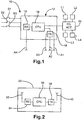
Figure 1 illustrates schematically a known form of passive entry system for a vehicle; -
Figure 2 illustrates schematically a token for use with the system ofFigure 1 ; -
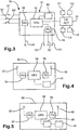
Figure 3 illustrates schematically a first form of passive entry system according to the invention; -
Figure 4 illustrates schematically a token for use with the system ofFigure 3 ; and -
Figure 5 illustrates schematically an alternative form of passive entry system according to the invention. - Referring to
Figure 1 , a known form of passive entry system for a vehicle is shown generally at 10. Thepassive entry system 10 includes a vehicle transceiver unit (VTU) 12 comprising a central processing unit (CPU) 14, connected to atransmitter 16 and to areceiver 18. - The
transmitter 16 is connected to a plurality of antennas A1 - A3 which serve to transmit electromagnetic signals generated by thetransmitter 16. Similarly, thereceiver 18 is connected to an antenna A4 which serves to receive electromagnetic signals received by thereceiver 18, as described below. - Also connected to the
VTU 12 are a plurality of switches. In the illustrated embodiment, there are three switches S1 - S3 connected to theCPU 14 within theVTU 12, each switch being located on a respective door of the vehicle. Switch S1, for example, is located on the driver's door of the vehicle whilst switch S2 is located on the passenger or "assist" door and switch S3 on the back door of the vehicle. - The
CPU 14 in theVTU 12 is also connected to a lockactuator control unit 20 which communicates with a plurality of lock actuators L1 - L4 for locking and unlocking selected doors of the vehicle. - Referring next to
Figure 2 , this illustrates a known form ofuser transceiver unit 30 referred to hereafter as a "token". Thetoken 30 takes the form of a relatively small, plastic housing within which is contained afirst antenna arrangement 32, areceiver unit 34, an central processing unit (CPU) 36, atransmitter unit 38 and a transmittingantenna system 40. The electronic composition of such units will be well understood by the skilled person with reference to the function thereof as indicated below and are not, therefore, described in detail herein. - Operation of the system of
Figure 1 and the token ofFigure 2 will now be described. - Initially, the system remains dormant. No signals are transmitted either by the
VTU 12 or by thetoken 30. The vehicle doors (not shown) are locked. To unlock the vehicle, the user approaches the vehicle carrying thetoken 30 either in hand or in a pocket or bag. There is no requirement for the user to have manual access to the token since the system is passive and manual operation of the token is not necessary. - To open, for example, the driver's door, the user approaches the door and presses the switch S1 located on the door itself. Pressing of the switch S1 causes an electrical current to flow therethrough, which is detected by the
CPU 14. TheCPU 14 then generates a command signal in the form of a 48-bit digital signal which includes a unique 8-bit identifier portion. The command signal is applied to thetransmitter unit 16 for transmission. - The
transmitter unit 16 is arranged to modulate the command signal with a low frequency (LF) carrier signal at approximately 125kHz, amplify it and then transmit it via one or more of the antennas A1 - A3. Usually, the command signal is transmitted via the antenna corresponding to the switch pressed by the user. The antennas A1 - A3 are arranged such that the range of the transmitted command signal, hereafter termed the threshold range, does not exceed approximately 2m from the vehicle. The reason for this range restriction is that it is desired to prevent a situation whereby a thief can unlock the vehicle doors by pressing the relevant switch S1 - S3 on the vehicle whilst the owner, who is in possession of the token, is too far away to take preventative action. - After transmission of the command signal, the
CPU 14 applies a predetermined algorithm to the identifier portion of the command signal to produce a unique reference value for reasons which are described below. - If the
token 30 is within the threshold range of the transmitted command signal, the signal is received by thereceiver unit 34 in thetoken 30 via thefirst antenna arrangement 32. Thereceiver unit 34 applies the command signal to theCPU 36 which applies the predetermined algorithm to the identifier portion of the command signal to produce a unique token value. The token value is then modulated by thetransmitter unit 38 with a carrier signal having a frequency of approximately 432MHz, amplified and is then transmitted back to the vehicle. - The transmitted signal representing the token value is received by the
receiver unit 18 within theVTU 12. Thereceiver unit 18 demodulates the signal to extract the token value and applies the token value to theCPU 14. TheCPU 14 then compares the token value with the reference value generated previously. If the token value matches the reference value, then theCPU 14 sends an UNLOCK signal to thelock actuator controller 20 to control the relevant lock or locks L1 - L4 thereby to unlock the relevant vehicle door. In some systems, pressing the switch twice in quick succession unlocks two or more of the vehicle doors. - The system is such that the signal sent by the CPU to the lock actuator controller toggles between LOCK and UNLOCK, depending on the initial condition of the door, i.e. whether the door was locked or unlocked when the signal is sent.
- The above description is given by way of example only. Existing passive entry systems may differ slightly in terms of construction or function from the system described above. However, all will be well understood by the skilled person and it will be appreciated that the present invention is applicable to substantially all passive entry systems and not solely to a system which operates as described above.
- As described above, a disadvantage of passive entry systems is that, provided the token 30 is within the threshold range of the command signal from the
VTU 12, almost irrespective of its actual location, it may be possible for an unauthorised person, such as a thief, to gain access to the vehicle simply by operating one of the switches on the vehicle doors. Once access to the vehicle is gained, the vehicle could be "hot wired" to start the engine, the interior could be vandalised or belongings in the vehicle could be stolen. - Such a situation might arise, for example, if the vehicle is parked in close proximity to the owner's house. In this case, the distance between the vehicle and the token within the house might be less than the threshold range of the command signal, in which case a potential thief merely has to operate one of the door switches S1 - S3. As described above, the
VTU 12 will transmit the command signal to the token 30 which will respond with the correct code or token value, regardless of the fact that the token itself 30 is not in the possession of the thief, thereby permitting the vehicle door to be opened. -
Figures 3 and 4 together illustrate a first form of passive entry system according to the invention which aims to address this drawback. The system of the invention comprises all of the features of the prior art system described with reference toFigure 1 . However, in the system ofFigures 3 and 4 , theVTU 12 is additionally provided with atimer 60 connected to theCPU 14. - Similarly, the token 30 includes all of the features of the token described with reference to
Figure 2 but additionally includesmeans 42, such as a transducer, connected to theCPU 36, for generating a tactile, visual or audible signal to the user, as described below. - In use, when the
CPU 14 sends a LOCK signal to thedoor lock actuator 20, thetimer 60 begins to count down a predetermined time period. The time period may be selected as desired but in the preferred embodiment is at least five minutes. During this period, theCPU 14 periodically or continuously generates an interrogation signal, similar in form to the command signal, and transmits it via thetransmitter 16 and antennas A1 - A3 as described above. - If the token 30 is still within the threshold range of the antennas A1 - A3, the interrogation signal is received by the token's
receiver unit 34 and encoded with the encryption algorithm by theCPU 36. Thetransmitter unit 38 then transmits the encrypted interrogation signal back to the VTU whereby it is received by thereceiver unit 18. The purpose of this periodic or continuous scanning function is to determine whether the token has remained within the threshold range of theVTU 12 after the vehicle is locked. - If the
receiver unit 18 in theVTU 12 is still receiving a reply signal from the token in response to the scanning function after the countdown time on thetimer 60 reaches zero, then theCPU 14 generates an alert signal which is applied to thetransmitter unit 16, modulated and then transmitted to the token 30 via the antennas A1 - A3. Thereceiver unit 34 in the token receives the alert signal from theVTU 12 and applies it to theCPU 36. TheCPU 36 then controls thetransducer 42 to generate a tactile, visual or audible signal (depending on the nature of the transducer provided) to the user. For example, the transducer may comprise a buzzer or siren to generate an audible signal to the user, or may comprise an LED or other device for emitting a visible alert signal. - The purpose of the signal is to advise the user that the token is still within range of the vehicle and the security risk that this presents. The user is then free to relocate the token in a position in which it is outside the threshold range of the vehicle.
- In a second embodiment of the invention (not shown), alternatively or in addition to the transducer in the token, the system is provided with a means for selectively disconnecting or deactivating one or more of the antennas A1 - A3 in response to the reply signal from the token still being received by the
receiver unit 18 when the time period on thetimer 60 expires. This means may be provided by a function in theCPU 14 or thetransmitter 16 which selects which of the antennas A1 - A3 the alert signal is transmitted via. Alternatively, means (not shown) may be provided for mechanically or electronically disconnecting the relevant antenna or antennas A1 - A3 from thetransmitter 16. Such means may comprise mechanical switches or contacts, or electronic switches or circuits such as transistors, in a manner which will be well understood by the skilled person. - Advantageously, during the scanning function, the
CPU 14 is able to determine which of the antennas A1 - A3 is within range of the token and thereby to disconnect or deactivate that antenna. This is achieved by "cycling" the antennas, i.e. transmitting the interrogation signal via each antenna A 1 - A3 individually in sequence and waiting for the reply signal from the token. When the reply signal is received, theCPU 14 identifies which antenna the interrogation signal was transmitted via and then disconnects or deactivates that antenna as desired. - In a third embodiment of the invention (not shown) the system is arranged to deactivate the passive entry function after the countdown time on the
timer 60 reaches zero. This can be achieved in a number of ways. For example, when the timer reaches zero and the token 30 is determined to be still in range of the vehicle as described above, the CPU initiates a routine whereby the UNLOCK signal is no longer generated when any of the door switches S1 - S3 is operated. Since the UNLOCK signal is no longer applied to the lockactuator control unit 20, the vehicle doors will not be unlocked even if the token 30 is in range of the vehicle. - In a fourth embodiment of the invention (not shown), the door switches may be deactivated, for example by the
CPU 14 no longer generating the command signal when any of the door switches S1 - S3 are operated, or through the switches being mechanically or electronically disconnected from theVTU 12. Thus, when a door switch is pressed, either theCPU 14 ignores this action and does not generate the command signal or the action is not communicated to the CPU owing to the disconnected status of the switches. The manner in which this functionality can be achieved will be well understood by those skilled in the art. - In a fifth embodiment of the invention (not shown), the
VTU 12 is arranged to generate and transmit a disable signal to the token 30 which causes the token to be disabled or deactivated. In this embodiment, when thetimer 60 reaches zero, the processor generates a disable signal which is applied to the transmitter and transmitted via one or more of the antennas A1 - A3. The token 30 receives the disable signal and theCPU 36 then executes a routine whereby either it no longer responds on receiving a command signal from theVTU 12 or it responds to the command signal with an error signal such that the processor in the VTU does not generate the UNLOCK signal on receipt thereof. - The error signal may be generated through the
CPU 36 changing the command signal on receipt thereof, for example by changing the value of one of the bits in the identifier portion of the signal such that the token value generated following application of the algorithm is not identical to the reference value calculated by theCPU 14 in theVTU 12. - In any of the above described embodiments, the system can be reset by the user such that full passive entry functionality is restored. The reset function can be achieved, for example, by the user entering a predetermined sequence on two or more buttons disposed on the token or by pressing a dedicated button thereon. This predetermined sequence causes the
CPU 14 to generate a reset signal which is transmitted to theVTU 12 by thetransmitter 38 andsecond antenna arrangement 40. The reset signal is received by thereceiver unit 18 in theVTU 12 and applied to theCPU 14 which resets the system such that normal passive entry operation is restored. - It will be understood by the skilled person that the second to the fifth embodiments of the invention may employ all of the features or elements of the first embodiment of the invention. Specifically, the provision of a timer is common to each of these embodiments in order to determine for how long the token has been within the threshold range of the vehicle after the vehicle has been locked, as is means (which may be provided by a functionality or routine of the CPU itself as opposed to a separate and distinct element in either the VTU or the token) to control the operation of the system if the token has so been in range for a predetermined length of time.
- A further problem with conventional keyless entry systems has been identified by the applicant company. Specifically, even if the token 30 is located at a distance from the vehicle which is significantly greater than the predetermined threshold range of the transmitted command signal, it is theoretically possible for a thief or unauthorised person to extend the effective threshold range of the command signal to an extent which places the token within such a range.
- This extension of the threshold range might be achieved by the thief gaining access to the vehicle wiring harness and, for example, either connecting an extension wire to the antennas A1 - A3 or electronically boosting the strength of the command signal transmitted by the VTU. In the former situation, should the thief be able to locate part of the extension wire within 2m (the threshold range of the command signal) of the token 30, then the token will receive the command signal and respond in the normal way.
- In the latter situation, the boosted command signal will have a greater range than the threshold range and this may be sufficient to reach the token. Both modifications will therefore have the effect of increasing the threshold range of the command signal so that, even if the 30 token is significantly distanced from the vehicle, the vehicle doors can still be opened. It should be noted that this is possible because the UHF signal transmitted by the token has a range of over thirty metres.
- To address this further problem, a sixth embodiment of the present invention, shown in
Figure 5 , provides a means whereby the token does not operate correctly if it has remained static for a predetermined period of time immediately prior to receipt of the command signal from theVTU 12. In this case, the token 30 additionally comprises atimer unit 46 connected to theCPU 36 and amotion sensor 48 connected to thetimer unit 46. - In use, any movement of the token 30, such as by virtue of the user picking up or carrying the token, is detected by the
motion sensor 48 which sends a movement signal to thetimer unit 46. Thetimer unit 46 measures the time between successive movement signals from themotion sensor 48. When a command signal from theVTU 12 is received by thereceiver unit 34 and applied to theCPU 36, before responding by applying the algorithm and retransmitting the command signal to the VTU, theCPU 36 generates and sends a request signal to thetimer unit 46 requesting the time interval since the last movement signal was received by thetimer unit 46 from themotion sensor 48. - If the time interval since the last movement signal was received by the
timer unit 46 exceeds a predetermined duration, suggesting that it is not on the owners' person and that the command signal from theVTU 12 may have been generated as a result of an attempt by a third party to gain unauthorised access to the vehicle, then theCPU 36 executes a routine whereby either it does not respond to the command signal, as in the case of embodiment 3 or alternatively sends an error signal to the VTU such that the processor does not generate the lock/unlock signal, as in the case of embodiment 4 above. The error signal may additionally or alternatively be used to trigger the vehicle alarm system, where one is fitted. - Only if the time interval since the last movement signal was received by the
timer unit 46 is within the predetermined duration does the token respond correctly to a command signal from theVTU 12 such that the vehicle doors are unlocked. - This particularly advantageous embodiment hinders or substantially prevents any attempt to access the vehicle by extending the effective range of the transmitted command signal from the VTU, either by boosting the power of the electromagnetic signal or by accessing the vehicle wiring harness and extending the length of the antennas. The token will only respond correctly to the command signal if it has been moved within a predetermined interval prior to receipt of the command signal, as it would normally have been if legitimately used by the user.
- In
Figures 1 - 5 , features of the prior art and the embodiments of the invention such as receiver units, transmitter units and timer units are illustrated as separate and distinct elements. It will be appreciated, however, that the functions of these elements may be incorporated into the CPUs of theVTU 10 andtoken 30, respectively, and that the CPUs themselves may comprise ASICs or other suitable IC chips. - It will be appreciated that the present invention provides a number of separate or combined solutions to a new problem which has been identified by the present applicants in respect of passive or keyless entry systems. It will further be appreciated that the embodiments described above may be implemented individually or in combination and in a number of different ways.
- For example, the invention is equally applicable to the vehicle's ignition system and/or immobiliser system as would be well understood by the skilled person.
Claims (7)
- A passive entry system (10) for a vehicle comprising first transceiver means (12) associated with the vehicle and second transceiver means (30) associated with a user of the vehicle, at least one of the first and second transceiver means (12,30) being arranged selectively to communicate with the other when the second transceiver means (30) is located within a predetermined range of the vehicle;
the first and second transceiver means comprises a transmitter (16,38) and a receiver (18,34) for transmitting and receiving signals, respectively, via one or more antennas (A1-A4:32,40), and processor means (14,36) for controlling the transceiver means;
the system comprises first means for determining whether the second transceiver means (30) is located within a predetermined range of the vehicle a predetermined period after locking of the vehicle doors, the first means including a timer (60) associated with the first transceiver means (12) for timing said predetermined period; and second means for controlling the passive entry system in response thereto, the second means including the processor means (14) of the first transceiver means (12);
characterised in that if the first means determines that the second transceiver means (30) is located within said predetermined range of the vehicle at the end of the predetermined period, said processor means (14) controls said system (10) to do at least one of the following:
generate an alert signal, said alert signal being transmitted to said second transceiver means (30) by said transmitter (16) via said one or more antennas (A1-A3); activate an alarm system on said vehicle; disable, deactivate or disconnect one or more of said antennas (A1-A4); disable or deactivate said system; and to generate a disable signal, said disable signal being transmitted to said second transceiver means (30) via said one or more antennas (A1-A3). - A passive entry system (10) for a vehicle comprising first transceiver means (12) associated with the vehicle and second transceiver means (30) associated with a user of the vehicle, at least one of the first and second transceiver means (12,30) being arranged selectively to communicate with the other when the second transceiver means (30) is located within a predetermined range of the vehicle;
the first and second transceiver means (12,30) comprising a transmitter (16,38) and a receiver (18,34) for transmitting and receiving signals, respectively, via one or more antennas (A1-A4;32,34), and processor means for controlling the transceiver means, including a first central processing unit, hereinafter called first CPU (14) for controlling the first transceiver means (12) and a second central processing unit, hereinafter called second CPU (36) for controlling the second transceiver means (30);
the system comprising first means for determining whether the second transceiver means (30) has been moved during a predetermined period before communication between the first and second transceiver means (12,30), the first means including a motion sensor (48) to detect movement of the second transceiver means (30), the second CPU (36), and a timer unit (46) for measuring successive movement signals from the motion sensor (48); and second means for controlling the passive entry system in response thereto, the second means including the first CPU (14);
characterised in that, in response to receipt of a command signal from the first transceiver means (12), the second CPU (36) requests from the timing unit (46) the time interval since the last movement signal was received from the motion sensor (48), and if this exceeds the predetermined period, the second CPU (36) sends an error signal to the first transceiver means (12) such that the first CPU (14) does not generate the lock/unlock signal. - A system as claimed in claim 1, wherein in response to said alert signal being received, said second transceiver means (30) is arranged to deliver a tactile, audible or visual signal to said user.
- A system as claimed in claim 1 or 3, wherein said processor means (14) is operable to disconnect one or more of the switch means from the first transceiver means.
- A system as claimed in claim 1, 3 or 4, wherein in response to said disable signal being received, said second transceiver means (30) is disabled.
- A system as claimed in claim 1 or 5, wherein the processor means (14) is arranged to activate an alarm system of the vehicle.
- A system as claimed in claim 2, wherein the second CPU (36) is arranged to activate an alarm system of the vehicle in response to receipt of the error signal.
Applications Claiming Priority (2)
| Application Number | Priority Date | Filing Date | Title |
|---|---|---|---|
| GB0315992A GB0315992D0 (en) | 2003-07-09 | 2003-07-09 | Security system |
| PCT/GB2004/003014 WO2005006262A1 (en) | 2003-07-09 | 2004-07-09 | Security system |
Publications (2)
| Publication Number | Publication Date |
|---|---|
| EP1646987A1 EP1646987A1 (en) | 2006-04-19 |
| EP1646987B1 true EP1646987B1 (en) | 2012-05-09 |
Family
ID=27741815
Family Applications (1)
| Application Number | Title | Priority Date | Filing Date |
|---|---|---|---|
| EP04743355A Expired - Lifetime EP1646987B1 (en) | 2003-07-09 | 2004-07-09 | Security system |
Country Status (3)
| Country | Link |
|---|---|
| EP (1) | EP1646987B1 (en) |
| GB (1) | GB0315992D0 (en) |
| WO (1) | WO2005006262A1 (en) |
Cited By (1)
| Publication number | Priority date | Publication date | Assignee | Title |
|---|---|---|---|---|
| CN108944783A (en) * | 2017-05-25 | 2018-12-07 | 通用汽车环球科技运作有限责任公司 | For be additionally related to multi-functional passive entry with vehicle launch and the system and method for determining device position |
Family Cites Families (6)
| Publication number | Priority date | Publication date | Assignee | Title |
|---|---|---|---|---|
| GB9400595D0 (en) * | 1994-01-14 | 1994-03-09 | Flounders Michael | Improvements in vehicle security systems |
| DE4422906C2 (en) * | 1994-06-30 | 1996-12-05 | Telefunken Microelectron | Method for operating a locking system for lockable objects |
| AU739172B2 (en) * | 1997-10-10 | 2001-10-04 | Robert Bosch Gmbh | An entry system |
| US6236333B1 (en) * | 1998-06-17 | 2001-05-22 | Lear Automotive Dearborn, Inc. | Passive remote keyless entry system |
| US6034617A (en) | 1998-12-04 | 2000-03-07 | Eaton Corporation | Operator intent based passive keyless vehicle control system |
| DE60028586T2 (en) * | 2000-12-22 | 2006-12-21 | Ford Global Technologies, LLC, Dearborn | A system for vehicle status display |
-
2003
- 2003-07-09 GB GB0315992A patent/GB0315992D0/en not_active Ceased
-
2004
- 2004-07-09 WO PCT/GB2004/003014 patent/WO2005006262A1/en not_active Ceased
- 2004-07-09 EP EP04743355A patent/EP1646987B1/en not_active Expired - Lifetime
Cited By (1)
| Publication number | Priority date | Publication date | Assignee | Title |
|---|---|---|---|---|
| CN108944783A (en) * | 2017-05-25 | 2018-12-07 | 通用汽车环球科技运作有限责任公司 | For be additionally related to multi-functional passive entry with vehicle launch and the system and method for determining device position |
Also Published As
| Publication number | Publication date |
|---|---|
| GB0315992D0 (en) | 2003-08-13 |
| EP1646987A1 (en) | 2006-04-19 |
| WO2005006262A1 (en) | 2005-01-20 |
Similar Documents
| Publication | Publication Date | Title |
|---|---|---|
| US6127922A (en) | Vehicle security system with remote systems control | |
| US7394350B2 (en) | Power-saving on-vehicle controller | |
| US6819229B2 (en) | Countermeasure system and method for vehicle passive entry system | |
| US5783994A (en) | Vehicle security system with combined key fob and keypad anti-driveaway protection | |
| US6963794B2 (en) | Locking system for a motor vehicle | |
| US6437683B1 (en) | Keyless security entry control method for motor vehicles | |
| EP1112203B1 (en) | Remote control key system having keyless entry functions and a vehicle immobilizing function in common keyhead | |
| US20030014164A1 (en) | Apparatus and method for disabling a remote control unit of an automobile | |
| US20120158214A1 (en) | Bi-directional vhf uhf polling mechanisms for intelligent peps polling | |
| EP1006249A2 (en) | Operator intent based passive keyless vehicle control system | |
| US7005960B2 (en) | Vehicle remote control system with selectable outputs and associated methods | |
| GB2421107A (en) | A remote entry system for a vehicle having passive and remote keyless entry functions | |
| JPH09175332A (en) | Start-up key and inter-vehicle communication device with functions to prevent runaway and remote control | |
| KR20040021550A (en) | Key-less locking system for vehicle, especially motor vehicle | |
| US11046287B1 (en) | System and method for vehicle theft prevention | |
| JP2025134687A (en) | Systems etc. | |
| WO2002025040A1 (en) | Proximity activated entry system | |
| EP3671668B1 (en) | Electronic key and method for operating an electronic key | |
| US6850154B2 (en) | Method and device for protecting motor vehicles against theft | |
| EP1646987A1 (en) | Security system | |
| EP1218227B1 (en) | Improved security system | |
| JP2002339609A (en) | Transmitter for keyless entry system | |
| EP2091791A1 (en) | Keyless access system and method for a truck and truck equipped with such a system | |
| GB2275552A (en) | A system for the remote operation of a security device | |
| WO2001025062A1 (en) | Exterior mounted access device control for a vehicle passive entry system |
Legal Events
| Date | Code | Title | Description |
|---|---|---|---|
| PUAI | Public reference made under article 153(3) epc to a published international application that has entered the european phase |
Free format text: ORIGINAL CODE: 0009012 |
|
| 17P | Request for examination filed |
Effective date: 20060209 |
|
| AK | Designated contracting states |
Kind code of ref document: A1 Designated state(s): DE FR GB |
|
| DAX | Request for extension of the european patent (deleted) | ||
| RBV | Designated contracting states (corrected) |
Designated state(s): DE FR GB |
|
| RAP1 | Party data changed (applicant data changed or rights of an application transferred) |
Owner name: NISSAN MOTOR MANUFACTURING (UK) LTD. |
|
| 17Q | First examination report despatched |
Effective date: 20100903 |
|
| GRAP | Despatch of communication of intention to grant a patent |
Free format text: ORIGINAL CODE: EPIDOSNIGR1 |
|
| GRAS | Grant fee paid |
Free format text: ORIGINAL CODE: EPIDOSNIGR3 |
|
| GRAA | (expected) grant |
Free format text: ORIGINAL CODE: 0009210 |
|
| AK | Designated contracting states |
Kind code of ref document: B1 Designated state(s): DE FR GB |
|
| REG | Reference to a national code |
Ref country code: GB Ref legal event code: FG4D |
|
| REG | Reference to a national code |
Ref country code: DE Ref legal event code: R096 Ref document number: 602004037775 Country of ref document: DE Effective date: 20120705 |
|
| PLBE | No opposition filed within time limit |
Free format text: ORIGINAL CODE: 0009261 |
|
| STAA | Information on the status of an ep patent application or granted ep patent |
Free format text: STATUS: NO OPPOSITION FILED WITHIN TIME LIMIT |
|
| 26N | No opposition filed |
Effective date: 20130212 |
|
| REG | Reference to a national code |
Ref country code: DE Ref legal event code: R097 Ref document number: 602004037775 Country of ref document: DE Effective date: 20130212 |
|
| PGFP | Annual fee paid to national office [announced via postgrant information from national office to epo] |
Ref country code: DE Payment date: 20140725 Year of fee payment: 11 |
|
| PGFP | Annual fee paid to national office [announced via postgrant information from national office to epo] |
Ref country code: FR Payment date: 20140725 Year of fee payment: 11 |
|
| REG | Reference to a national code |
Ref country code: DE Ref legal event code: R119 Ref document number: 602004037775 Country of ref document: DE |
|
| PG25 | Lapsed in a contracting state [announced via postgrant information from national office to epo] |
Ref country code: DE Free format text: LAPSE BECAUSE OF NON-PAYMENT OF DUE FEES Effective date: 20160202 |
|
| REG | Reference to a national code |
Ref country code: FR Ref legal event code: ST Effective date: 20160331 |
|
| PG25 | Lapsed in a contracting state [announced via postgrant information from national office to epo] |
Ref country code: FR Free format text: LAPSE BECAUSE OF NON-PAYMENT OF DUE FEES Effective date: 20150731 |
|
| PGFP | Annual fee paid to national office [announced via postgrant information from national office to epo] |
Ref country code: GB Payment date: 20190715 Year of fee payment: 16 |
|
| GBPC | Gb: european patent ceased through non-payment of renewal fee |
Effective date: 20200709 |
|
| PG25 | Lapsed in a contracting state [announced via postgrant information from national office to epo] |
Ref country code: GB Free format text: LAPSE BECAUSE OF NON-PAYMENT OF DUE FEES Effective date: 20200709 |