EP1646889B1 - A seismic measuring system including gps receivers - Google Patents
A seismic measuring system including gps receivers Download PDFInfo
- Publication number
- EP1646889B1 EP1646889B1 EP04737961A EP04737961A EP1646889B1 EP 1646889 B1 EP1646889 B1 EP 1646889B1 EP 04737961 A EP04737961 A EP 04737961A EP 04737961 A EP04737961 A EP 04737961A EP 1646889 B1 EP1646889 B1 EP 1646889B1
- Authority
- EP
- European Patent Office
- Prior art keywords
- gps
- receivers
- slave
- signals
- tracking
- Prior art date
- Legal status (The legal status is an assumption and is not a legal conclusion. Google has not performed a legal analysis and makes no representation as to the accuracy of the status listed.)
- Active
Links
Images

Classifications
-
- G—PHYSICS
- G01—MEASURING; TESTING
- G01V—GEOPHYSICS; GRAVITATIONAL MEASUREMENTS; DETECTING MASSES OR OBJECTS; TAGS
- G01V1/00—Seismology; Seismic or acoustic prospecting or detecting
- G01V1/003—Seismic data acquisition in general, e.g. survey design
-
- G—PHYSICS
- G01—MEASURING; TESTING
- G01V—GEOPHYSICS; GRAVITATIONAL MEASUREMENTS; DETECTING MASSES OR OBJECTS; TAGS
- G01V3/00—Electric or magnetic prospecting or detecting; Measuring magnetic field characteristics of the earth, e.g. declination, deviation
- G01V3/18—Electric or magnetic prospecting or detecting; Measuring magnetic field characteristics of the earth, e.g. declination, deviation specially adapted for well-logging
- G01V3/26—Electric or magnetic prospecting or detecting; Measuring magnetic field characteristics of the earth, e.g. declination, deviation specially adapted for well-logging operating with magnetic or electric fields produced or modified either by the surrounding earth formation or by the detecting device
- G01V3/28—Electric or magnetic prospecting or detecting; Measuring magnetic field characteristics of the earth, e.g. declination, deviation specially adapted for well-logging operating with magnetic or electric fields produced or modified either by the surrounding earth formation or by the detecting device using induction coils
-
- G—PHYSICS
- G01—MEASURING; TESTING
- G01S—RADIO DIRECTION-FINDING; RADIO NAVIGATION; DETERMINING DISTANCE OR VELOCITY BY USE OF RADIO WAVES; LOCATING OR PRESENCE-DETECTING BY USE OF THE REFLECTION OR RERADIATION OF RADIO WAVES; ANALOGOUS ARRANGEMENTS USING OTHER WAVES
- G01S19/00—Satellite radio beacon positioning systems; Determining position, velocity or attitude using signals transmitted by such systems
- G01S19/01—Satellite radio beacon positioning systems transmitting time-stamped messages, e.g. GPS [Global Positioning System], GLONASS [Global Orbiting Navigation Satellite System] or GALILEO
- G01S19/03—Cooperating elements; Interaction or communication between different cooperating elements or between cooperating elements and receivers
- G01S19/05—Cooperating elements; Interaction or communication between different cooperating elements or between cooperating elements and receivers providing aiding data
-
- G—PHYSICS
- G01—MEASURING; TESTING
- G01S—RADIO DIRECTION-FINDING; RADIO NAVIGATION; DETERMINING DISTANCE OR VELOCITY BY USE OF RADIO WAVES; LOCATING OR PRESENCE-DETECTING BY USE OF THE REFLECTION OR RERADIATION OF RADIO WAVES; ANALOGOUS ARRANGEMENTS USING OTHER WAVES
- G01S19/00—Satellite radio beacon positioning systems; Determining position, velocity or attitude using signals transmitted by such systems
- G01S19/38—Determining a navigation solution using signals transmitted by a satellite radio beacon positioning system
- G01S19/39—Determining a navigation solution using signals transmitted by a satellite radio beacon positioning system the satellite radio beacon positioning system transmitting time-stamped messages, e.g. GPS [Global Positioning System], GLONASS [Global Orbiting Navigation Satellite System] or GALILEO
- G01S19/42—Determining position
- G01S19/43—Determining position using carrier phase measurements, e.g. kinematic positioning; using long or short baseline interferometry
- G01S19/44—Carrier phase ambiguity resolution; Floating ambiguity; LAMBDA [Least-squares AMBiguity Decorrelation Adjustment] method
-
- G—PHYSICS
- G01—MEASURING; TESTING
- G01V—GEOPHYSICS; GRAVITATIONAL MEASUREMENTS; DETECTING MASSES OR OBJECTS; TAGS
- G01V1/00—Seismology; Seismic or acoustic prospecting or detecting
- G01V1/16—Receiving elements for seismic signals; Arrangements or adaptations of receiving elements
-
- G—PHYSICS
- G01—MEASURING; TESTING
- G01V—GEOPHYSICS; GRAVITATIONAL MEASUREMENTS; DETECTING MASSES OR OBJECTS; TAGS
- G01V1/00—Seismology; Seismic or acoustic prospecting or detecting
- G01V1/22—Transmitting seismic signals to recording or processing apparatus
-
- G—PHYSICS
- G01—MEASURING; TESTING
- G01V—GEOPHYSICS; GRAVITATIONAL MEASUREMENTS; DETECTING MASSES OR OBJECTS; TAGS
- G01V1/00—Seismology; Seismic or acoustic prospecting or detecting
- G01V1/24—Recording seismic data
- G01V1/26—Reference-signal-transmitting devices, e.g. indicating moment of firing of shot
Definitions
- the invention relates generally to seismic data collection systems and, in particular, to systems for collecting and analyzing three-dimensional seismic data.
- Systems for analyzing three-dimensional seismic data collect seismic measurements from configurations of geophones that are attached to and communicate with digitizer units (DUs), that produce signals that correspond to the seismic measurements.
- the DUs which are placed at selected locations along cables that span a site of interest, take readings from the configurations of geophones and send corresponding signals over the cables to a data recording and control center.
- the data is used to determine, for example, the likelihood that oil reserves are present on the site.
- a typical site may include thousands of DUs, each with an associated configuration of geophones.
- the locations of the DUs must be known to within tight vertical and horizontal accuracy limits, and generally, the locations of the respective DUs are individually determined using optical survey techniques, GPS RTK "back-pack" systems or GPS/INS systems.
- the sites can no longer be cleared, that is, foliage cannot be removed at the selected locations of the DUs, and thus, the process of determining the locations of the DUs is made even more time consuming and complex when lines of sight are blocked.
- the geophone readings taken by the DUs must be synchronized to within tight timing limits.
- timing signals are sent along the cables and readings are taken at the various DUs in response to the signals. Accordingly, the lengths of the respective cables are limited, to avoid associated timing signal delays. Consequently, the area that can be tested at a given time is also limited by the lengths of the cables.
- US4589100 discloses a method and apparatus for positioning seismic arrays.
- a system for analyzing three-dimensional seismic data includes, in addition to the DUs, the geophones and the data recording and control center, a base GPS receiver and an associated antenna with a substantially unrestricted view of the sky and at the respective DUs low-power slave GPS receivers that acquire and track GPS satellite signals using tracking assistance information provided by the base GPS receiver.
- the slave GPS receivers can acquire and track GPS satellite signals that may be relatively weak at the receivers, due to conditions at the site, such as foliage canopies, and so forth.
- the system operates the slave GPS receivers and processes associated range information such that the precise positions of the respective DUs are calculated and synchronized timing information is provided to each DU, even if the sky views of the respective slave GPS receivers are substantially reduced.
- the associated slave GPS receiver uses the tracking assistance information to acquire and track GPS satellite signals from those satellites that are in the receiver's view.
- the slave GPS receiver then produces associated range information and provides the information to the data recording and control center.
- the data recording and control center collects the range information over an extended period of time, such as hours or days, as necessary.
- the center then batch processes the information, to produce a single computed position.
- the system can determine the position of the slave GPS receiver to within the tight vertical and horizontal tolerances required for seismic measurements, as long as the slave GPS receiver is able to observe and collect data from at least two satellites simultaneously for 3 or 4 relatively short time intervals at various sky positions during the extended period.
- the batch processing thus eliminates the need to continuously track the GPS satellite signals and/or to track the signals from the same set of satellites over the respective intervals.
- the data recording and control center thereafter provides the precise computed positions to the respective slave GPS receivers.
- the slave GPS receivers then use the position information and the tracking assistance information provided by the base GPS receiver to produce synchronized timing signals for use in controlling the collection of seismic data from the geophones.
- the timing signals include a 1 pulse per second strobe, which is tied to the codes in the GPS satellite signals, and the associated RS-232 time tag data.
- the timing signals remain synchronized over the system as long as a number of the slave GPS receivers individually continue to track the signals from at least one GPS satellite during a geophone data gathering operation.
- the slave GPS receivers that are tracking during the data gathering operation provide synchronized timing signals over the connecting cables to the neighboring non-tracking slave GPS slave receivers. Accordingly, the limit on cable lengths is essentially between the respective slave GPS receivers. This is in contrast to known prior systems in which the limit on the cable length must be met between the respective DUs and the control center.
- the system thus provides precise positioning information for the respective DUs and synchronized timing signals for the collection of data from the geophones using relatively inexpensive slave GPS receivers that have their acquisition and tracking performance enhanced by the tracking assistance information provided by a single base GPS receiver. Further, the system produces the precise positioning information and the synchronized timing signals in an environment in which GPS receivers operating in a conventional manner typically can not do so, because of, for example, foliage cover that interferes with the receipt of the GPS satellite signals at the respective GPS receivers.
- the system 100 includes a plurality of geophones 8 that supply seismic data to a data recording and control center 12 through DUs 7.
- the DUs are located in selected locations over a site of interest and are connected to the center by cables 14.
- the center 12 includes one or more workstations 2 and data storage devices 1 that process and store the data collected by the geophones.
- the signals from various cables 14 (only one of which is shown in the drawing) are supplied to the one or more workstations 2 through a multiplexer 4, which operates in a conventional manner.
- the system generally includes thousands of DUs, each with an associated configuration of geophones.
- the data recording and control center 12 further includes a base Global Positioning System (GPS) receiver 3 that receives signals from various GPS satellites 9 using a base GPS antenna 13, which is positioned to have a clear view of the sky.
- GPS Global Positioning System
- Slave GPS receivers 6, which may be relatively inexpensive low power L1 receivers, are located at the respective DUs 7.
- the slave GPS receivers 6 provide range information to the data recording and control center 12 and synchronized data collection timing signals to the DUs 7.
- certain or all of the slave GPS receivers 6 are located under or near various trees 11, such that at any given time the signals 10 from GPS satellites 9 in certain sky locations may be unavailable or weakened at various slave GPS receivers.
- the base GPS receiver 3 acquires and tracks the signals 10 from each of the GPS satellites in view, and at various times provides to the slave GPS receivers related tracking assistance information.
- the base GPS receiver provides as the tracking assistance information at least a list of the satellites then in view, and the associated Doppler frequency offsets and broadcast data symbols.
- the slave GPS receivers then use the tracking assistance information to acquire and track the signals from the various satellites using tracking loops with relatively narrow bandwidths. This allows the respective slave GPS receivers to utilize GPS satellite signals that are weak at the receivers.
- the slave GPS receivers may acquire and track signals that are 10 to 15 dB lower than the signals required by GPS receivers operating in a conventional manner, that is, without tracking assistance.
- Each slave GPS receiver 6 produces range information based on the satellite signals that the receiver can track at a given time, and the receiver provides the range information to the data recording and control center 12.
- the range information includes both code and carrier timing information for each of the signals being tracked.
- the center collects the range information over an extended period of time, for example, hours, days or weeks, and then batch processes the collected information, to calculate the precise latitude, longitude and height of the receiver. The center also calculates the quality of the collected range information, to ensure that the information used in the batch position calculations is sufficiently reliable, as discussed in more detail below.
- the batch processing of the range information calculates the position of the slave GPS receiver to within the tolerances required for seismic measurement.
- the batch processing thus allows the system to calculate the precise positions of the slave receivers without requiring that the slave GPS receiver continuously track the GPS satellite signals from multiple satellites and/or track the signals from the same set GPS satellites.
- the data recording and control center 12 batch processes the range data collected from a given fixed-position slave GPS receiver, to compute a single position, i.e.; latitude, longitude and height, and an associated position covariance.
- the batch processing involves multiple passes through the collected range data, with a first pass using all of the collected data, that is, all of the pseudorange and carrier phase information, to produce a global position estimate that is expected to be accurate to within 30 to 60 meters. As discussed, the accuracy is adversely affected by the overall quality of the range data.
- the range data is produced based on signals from the satellites that are in the view of the receiver at various times over an extended time period, that is, over a number of hours, days, and so forth.
- range data will be collected over a period of between 8 and 24 hours.
- the receiver may not have the same set of satellites in view over much of the extended period and/or may not have more than one satellite in view at particular times. Further, some of satellite signals may be distorted by large multipath components attributed to signals that are reflected to the receiver by the foliage or other nearby obstructions.
- the data recording and control center refmes the calculated position and position covariance using only the carrier phase measurements, which are less susceptible to multipath interference.
- the receiver starts with the estimated position and position covariance from the first pass and, in what is a computation intensive manner, resolves carrier cycle ambiguities to determine updated estimated positions and associated position covariances.
- the estimated position and the associated position covariance are updated at every code epoch in which two or more satellites are in view of the receiver, that is, when double differences can be calculated to resolve carrier cycle ambiguities.
- the accuracy of the position estimate at the end of the second pass is expected to be within 3 to 6 meters, with most of the error attributable to the height component.
- the third pass through the data holds the position and position covariance fixed to the best estimate from pass two and, based on the carrier phase measurement, looks for perceived movement.
- the processing selects for further processing data that are associated with little or no perceived movement.
- the processing may also selectively weight various data used in the further processing.
- the third pass processing calculates residuals of the double differenced carrier phase measurements with respect to the fixed position, and determines if the residuals show perceived movement.
- the residuals are accumulated over intervals in which there is continuity in the carrier phase measurement, that is, over periods in which there is no loss of lock or cycle slip.
- the processing determines measurement data is valid over a given interval if the sum of the squares of the residuals falls below a normalized threshold, and also, the rate of growth of the sum of the squares falls below a predetermined threshold. If both conditions are not met, the processing flags the associated series of carrier measurements as invalid for the entire interval between cycle slips.
- the processing may also assign weights to the respective measurements that are deemed valid.
- the processing may de-weight certain measurements to prevent correlated multipath errors, i.e., non-white noise errors, from adversely affecting the further processing.
- the de-weighting may, for example, take the form of using fewer of the measurements over a particular code epoch, i.e., one out of every four measurements, or using a larger standard deviation in the associated calculations.
- the processing then recalculates the estimated position based on the results of the third pass.
- the system thus eliminates from the calculations the measurements that are flagged as invalid and assigns appropriate weights to the remaining measurements, and produces a new position estimate and associated position covariance.
- the processing system next holds the position and position covariance fixed at the new estimates and repeats the third pass, that is, the processing step of determining the validity of and weightings for the measurements based on the associated residuals.
- the system may accept as good measurements particular measurements that showed perceived movement relative to the prior estimated position and position covariance but do not with respect to the new estimates.
- the processing system determines a next estimated position and associated position covariance using the updated weighting and validity determinations, and continues iterating in this manner, i.e., determining new weightings and a next estimate of position, until the estimated height changes by less than a predetermined threshold between iterations.
- the batch processing performed by the system differs substantially from the processing performed in known assisted GPS, or A-GPS, systems, which also referred to as e911 systems.
- A-GPS systems allow a GPS receiver in a cellular telephone essentially to determine an "instantaneous" position fix to within approximately 100 meters based on fast acquisition and tracking of signals simultaneously from 3 or 4 GPS satellites.
- the A-GPS systems are not designed to and do not meet the tight tolerances required for seismic measuring.
- the center provides the positions to the receivers.
- the slave GPS receivers 6 then use their positions and the tracking assistance information supplied by the base GPS receiver to produce synchronized 1 pulse per second timing signals that correspond to the timing of the codes in the received GPS satellite signals and also produce the associated RS-232 time tag message associated with the 1 pulse per second signal.
- the DUs use the timing signals (1 pulse per second and time tag message) to control the collection of data from the geophones.
- a given slave GPS receiver need only track the signals from a single GPS satellite at any given time in order to produce timing signals that are tied to the GPS codes, and thus, the DUs and associated slave GPS receivers should be able to maintain their timing signals in synchronism across the entire system.
- the system will still be able to gather data from the geophones by providing synchronized timing signals from nearby tracking slave GPS receivers to the non-tracking slave GPS receivers over the connecting cables 14.
- the slave GPS receivers may each send timing information over the cables, such that a given receiver can use its own timing information or the received timing information, as appropriate.
- the received timing signals remain synchronized as long as the receiver providing the timing signals is within approximately 1 kilometer of the receiver that must rely on the received signals.
- An alternative configuration of the system may use one of the receivers situated at the DUs as the source of the tracking assistance information.
- the installer may configure this receiver to supply the tracking assistance information to the various slave GPS receivers.
- the base GPS receiver 3, base GPS antenna 13 and the elevating tower 5 may not be necessary.
- the system may instead use two or more of the receivers situated at the DUs as sources of the tracking assistance information, with selected receivers being the source of the tracking assistance information for GPS satellites in particular regions of the sky.
- the deformation monitoring system 200 includes one or more base GPS receivers 3 with clear views to the sky that provide tracking assistance information and a plurality of slave GPS receivers 6 that act as monitoring devices.
- the slave GPS receivers are rigidly attached by poles 72 to a pipe 71, which is buried.
- Signal receivers 70 provide signals to and receive signals from the GPS receivers 6 and the cables 14.
- the data recording and control center 12 collects range information from the respective base and slave GPS receivers and batch processes the range information, to determine the precise positions of the respective slave GPS receivers along the pipe 71.
- the respective slave receivers continue to track the satellite signals, with the tracking assistance provided by the base GPS receiver or receivers, and provide range information to the data recording and control center.
- the center determines if there are changes in the positions of the respective slave GPS receivers that indicate deformation.
- the signal receivers 70 in the deformation monitoring system may also provide to the data recording and control center 12 other types of measurement data from secondary measurement devices, such strain gauges or tilt meters (not shown) that are attached to pipe 71.
- the data recording and control center may provide timing signals over the cables 14 to time tag movement "events," such as earthquakes. Should the system require measurement timing signals with more precision than can be provided over the cables, for the measurements made by these or other secondary devices, the system may instead use timing signals produced by the slave GPS receivers.
- the system described above has as one of its advantages locally producing, at each slave GPS receiver, timing signals that are synchronized over the entire system.
- cable length limitations are avoided by providing timing signals from a neighboring slave GPS receiver to a slave GPS receiver that has lost its timing signal by failing to continuously track the GPS satellites.
- the slave GPS receivers produce the timing signals in environments with restricted sky views, using the tracking assistance information provided by the base GPS receivers, and thus, can operate in areas in which conventional GPS receivers are ineffective.
- the system may operate without providing the tracking assistance information to the slave GPS receivers.
- the base GPS receiver provides to the data recording and control center range information, that is, pseudorange and carrier measurement information, to be used in the double difference calculations made during the batch processing.
- the slave GPS receivers initially operate in a conventional manner to acquire and track satellite signals from the satellites in view.
- the slave GPS receivers provide the associated range information to the data recording and control center and the center performs the batch processing, as discussed above. Thereafter, the center provides the slave GPS receivers with the position information, and the slave GPS receivers continue to acquire and track the satellite signals based on this position information.
- the slave GPS receivers operating in this manner, i.e., without tracking assistance, will have more difficulty continuously tracking the satellite signals.
- the slave GPS receivers will require timing signals from nearby receivers in order to provide synchronized timing signals to the DUs.
- the system operating in this manner is able to determine the precise positions of the slave GPS receivers, although the length of the extended period required to collect the range information will be longer when the tracking assistance is not provided to the slave GPS receivers.
Abstract
Description
- The present application claims the benefit of U.S. Provisional Patent Application Serial No.
60/488,124, which was filed on July 17, 2003, by Patrick C - The invention relates generally to seismic data collection systems and, in particular, to systems for collecting and analyzing three-dimensional seismic data.
- Systems for analyzing three-dimensional seismic data collect seismic measurements from configurations of geophones that are attached to and communicate with digitizer units (DUs), that produce signals that correspond to the seismic measurements. The DUs, which are placed at selected locations along cables that span a site of interest, take readings from the configurations of geophones and send corresponding signals over the cables to a data recording and control center. The data is used to determine, for example, the likelihood that oil reserves are present on the site. A typical site may include thousands of DUs, each with an associated configuration of geophones.
- Setting up and operating the measurement system is both time consuming and complex. The locations of the DUs must be known to within tight vertical and horizontal accuracy limits, and generally, the locations of the respective DUs are individually determined using optical survey techniques, GPS RTK "back-pack" systems or GPS/INS systems. In addition, the sites can no longer be cleared, that is, foliage cannot be removed at the selected locations of the DUs, and thus, the process of determining the locations of the DUs is made even more time consuming and complex when lines of sight are blocked.
- The geophone readings taken by the DUs must be synchronized to within tight timing limits. In prior known systems, timing signals are sent along the cables and readings are taken at the various DUs in response to the signals. Accordingly, the lengths of the respective cables are limited, to avoid associated timing signal delays. Consequently, the area that can be tested at a given time is also limited by the lengths of the cables.
-
US4589100 discloses a method and apparatus for positioning seismic arrays. - What is needed is a system that can be set up in a less time consuming manner and operate accurately over larger areas.
- A system for analyzing three-dimensional seismic data includes, in addition to the DUs, the geophones and the data recording and control center, a base GPS receiver and an associated antenna with a substantially unrestricted view of the sky and at the respective DUs low-power slave GPS receivers that acquire and track GPS satellite signals using tracking assistance information provided by the base GPS receiver. Using the tracking assistance information, the slave GPS receivers can acquire and track GPS satellite signals that may be relatively weak at the receivers, due to conditions at the site, such as foliage canopies, and so forth. Further, as discussed below, the system operates the slave GPS receivers and processes associated range information such that the precise positions of the respective DUs are calculated and synchronized timing information is provided to each DU, even if the sky views of the respective slave GPS receivers are substantially reduced.
- To determine the precise positions of a given DU, the associated slave GPS receiver uses the tracking assistance information to acquire and track GPS satellite signals from those satellites that are in the receiver's view. The slave GPS receiver then produces associated range information and provides the information to the data recording and control center. The data recording and control center collects the range information over an extended period of time, such as hours or days, as necessary. The center then batch processes the information, to produce a single computed position. By processing the information collected over an extended period of time, the system can determine the position of the slave GPS receiver to within the tight vertical and horizontal tolerances required for seismic measurements, as long as the slave GPS receiver is able to observe and collect data from at least two satellites simultaneously for 3 or 4 relatively short time intervals at various sky positions during the extended period. The batch processing thus eliminates the need to continuously track the GPS satellite signals and/or to track the signals from the same set of satellites over the respective intervals.
- The data recording and control center thereafter provides the precise computed positions to the respective slave GPS receivers. The slave GPS receivers then use the position information and the tracking assistance information provided by the base GPS receiver to produce synchronized timing signals for use in controlling the collection of seismic data from the geophones. The timing signals include a 1 pulse per second strobe, which is tied to the codes in the GPS satellite signals, and the associated RS-232 time tag data. The timing signals remain synchronized over the system as long as a number of the slave GPS receivers individually continue to track the signals from at least one GPS satellite during a geophone data gathering operation. The slave GPS receivers that are tracking during the data gathering operation provide synchronized timing signals over the connecting cables to the neighboring non-tracking slave GPS slave receivers. Accordingly, the limit on cable lengths is essentially between the respective slave GPS receivers. This is in contrast to known prior systems in which the limit on the cable length must be met between the respective DUs and the control center.
- The system thus provides precise positioning information for the respective DUs and synchronized timing signals for the collection of data from the geophones using relatively inexpensive slave GPS receivers that have their acquisition and tracking performance enhanced by the tracking assistance information provided by a single base GPS receiver. Further, the system produces the precise positioning information and the synchronized timing signals in an environment in which GPS receivers operating in a conventional manner typically can not do so, because of, for example, foliage cover that interferes with the receipt of the GPS satellite signals at the respective GPS receivers.
- The invention description below refers to the accompanying drawings, of which:
-
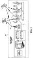
Fig. 1 is a functional block diagram of a seismic measuring system constructed in accordance with the invention; and -
Fig. 2 is a functional block diagram of a deformation monitoring system constructed in accordance with the invention. - Referring to the
Fig. 1 , asystem 100 for collecting and analyzing seismic measurements is depicted. Thesystem 100 includes a plurality ofgeophones 8 that supply seismic data to a data recording andcontrol center 12 through DUs 7. The DUs are located in selected locations over a site of interest and are connected to the center bycables 14. Thecenter 12 includes one ormore workstations 2 anddata storage devices 1 that process and store the data collected by the geophones. The signals from various cables 14 (only one of which is shown in the drawing) are supplied to the one ormore workstations 2 through amultiplexer 4, which operates in a conventional manner. The system generally includes thousands of DUs, each with an associated configuration of geophones. - The data recording and
control center 12 further includes a base Global Positioning System (GPS)receiver 3 that receives signals fromvarious GPS satellites 9 using abase GPS antenna 13, which is positioned to have a clear view of the sky. As depicted in the drawing, an elevated tower 5 may be necessary to provide theGPS antenna 13 with a clear sky view.Slave GPS receivers 6, which may be relatively inexpensive low power L1 receivers, are located at the respective DUs 7. As discussed in more detail below, theslave GPS receivers 6 provide range information to the data recording andcontrol center 12 and synchronized data collection timing signals to the DUs 7. As also depicted in the drawing, certain or all of theslave GPS receivers 6 are located under or nearvarious trees 11, such that at any given time thesignals 10 fromGPS satellites 9 in certain sky locations may be unavailable or weakened at various slave GPS receivers. - The
base GPS receiver 3 acquires and tracks thesignals 10 from each of the GPS satellites in view, and at various times provides to the slave GPS receivers related tracking assistance information. The base GPS receiver provides as the tracking assistance information at least a list of the satellites then in view, and the associated Doppler frequency offsets and broadcast data symbols. The slave GPS receivers then use the tracking assistance information to acquire and track the signals from the various satellites using tracking loops with relatively narrow bandwidths. This allows the respective slave GPS receivers to utilize GPS satellite signals that are weak at the receivers. For example, the slave GPS receivers may acquire and track signals that are 10 to 15 dB lower than the signals required by GPS receivers operating in a conventional manner, that is, without tracking assistance. - Each
slave GPS receiver 6 produces range information based on the satellite signals that the receiver can track at a given time, and the receiver provides the range information to the data recording andcontrol center 12. The range information includes both code and carrier timing information for each of the signals being tracked. The center collects the range information over an extended period of time, for example, hours, days or weeks, and then batch processes the collected information, to calculate the precise latitude, longitude and height of the receiver. The center also calculates the quality of the collected range information, to ensure that the information used in the batch position calculations is sufficiently reliable, as discussed in more detail below. - As long as the slave GPS receiver has tracked at least two satellites simultaneously for 3 or 4 relatively short time intervals at different sky locations during the extended period, the batch processing of the range information calculates the position of the slave GPS receiver to within the tolerances required for seismic measurement. The batch processing thus allows the system to calculate the precise positions of the slave receivers without requiring that the slave GPS receiver continuously track the GPS satellite signals from multiple satellites and/or track the signals from the same set GPS satellites.
- The data recording and
control center 12 batch processes the range data collected from a given fixed-position slave GPS receiver, to compute a single position, i.e.; latitude, longitude and height, and an associated position covariance. The batch processing involves multiple passes through the collected range data, with a first pass using all of the collected data, that is, all of the pseudorange and carrier phase information, to produce a global position estimate that is expected to be accurate to within 30 to 60 meters. As discussed, the accuracy is adversely affected by the overall quality of the range data. The range data is produced based on signals from the satellites that are in the view of the receiver at various times over an extended time period, that is, over a number of hours, days, and so forth. Generally, it is expected that range data will be collected over a period of between 8 and 24 hours. With slave GPS receiver's restricted view of the sky, because of foliage or other partial coverage, the receiver may not have the same set of satellites in view over much of the extended period and/or may not have more than one satellite in view at particular times. Further, some of satellite signals may be distorted by large multipath components attributed to signals that are reflected to the receiver by the foliage or other nearby obstructions. - As a next pass through the data, the data recording and control center refmes the calculated position and position covariance using only the carrier phase measurements, which are less susceptible to multipath interference. The receiver starts with the estimated position and position covariance from the first pass and, in what is a computation intensive manner, resolves carrier cycle ambiguities to determine updated estimated positions and associated position covariances. The estimated position and the associated position covariance are updated at every code epoch in which two or more satellites are in view of the receiver, that is, when double differences can be calculated to resolve carrier cycle ambiguities. The accuracy of the position estimate at the end of the second pass is expected to be within 3 to 6 meters, with most of the error attributable to the height component.
- The third pass through the data holds the position and position covariance fixed to the best estimate from pass two and, based on the carrier phase measurement, looks for perceived movement. The processing then selects for further processing data that are associated with little or no perceived movement. The processing may also selectively weight various data used in the further processing.
- More specifically, the third pass processing calculates residuals of the double differenced carrier phase measurements with respect to the fixed position, and determines if the residuals show perceived movement. The residuals are accumulated over intervals in which there is continuity in the carrier phase measurement, that is, over periods in which there is no loss of lock or cycle slip. The processing determines measurement data is valid over a given interval if the sum of the squares of the residuals falls below a normalized threshold, and also, the rate of growth of the sum of the squares falls below a predetermined threshold. If both conditions are not met, the processing flags the associated series of carrier measurements as invalid for the entire interval between cycle slips. The processing may also assign weights to the respective measurements that are deemed valid. Thus, the processing may de-weight certain measurements to prevent correlated multipath errors, i.e., non-white noise errors, from adversely affecting the further processing. The de-weighting may, for example, take the form of using fewer of the measurements over a particular code epoch, i.e., one out of every four measurements, or using a larger standard deviation in the associated calculations.
- The processing then recalculates the estimated position based on the results of the third pass. The system thus eliminates from the calculations the measurements that are flagged as invalid and assigns appropriate weights to the remaining measurements, and produces a new position estimate and associated position covariance.
- The processing system next holds the position and position covariance fixed at the new estimates and repeats the third pass, that is, the processing step of determining the validity of and weightings for the measurements based on the associated residuals. In this step the system may accept as good measurements particular measurements that showed perceived movement relative to the prior estimated position and position covariance but do not with respect to the new estimates. The processing system then determines a next estimated position and associated position covariance using the updated weighting and validity determinations, and continues iterating in this manner, i.e., determining new weightings and a next estimate of position, until the estimated height changes by less than a predetermined threshold between iterations.
- The batch processing operations are discussed in more detail in co-pending United States Provisional Application entitled METHOD FOR POSITIONING USING GPS IN A RESTRICTIVE COVERAGE ENVIRONMENT, and further identified by attorney matter number 016437-0218R, which is assigned to a common assignee.
- The batch processing performed by the system differs substantially from the processing performed in known assisted GPS, or A-GPS, systems, which also referred to as e911 systems. The A-GPS systems allow a GPS receiver in a cellular telephone essentially to determine an "instantaneous" position fix to within approximately 100 meters based on fast acquisition and tracking of signals simultaneously from 3 or 4 GPS satellites. The A-GPS systems are not designed to and do not meet the tight tolerances required for seismic measuring.
- Referring still to
Fig. 1 , once the data recording andcontrol center 12 has calculated the positions of the respectiveslave GPS receivers 6 to within the necessary tolerances, the center provides the positions to the receivers. Theslave GPS receivers 6 then use their positions and the tracking assistance information supplied by the base GPS receiver to produce synchronized 1 pulse per second timing signals that correspond to the timing of the codes in the received GPS satellite signals and also produce the associated RS-232 time tag message associated with the 1 pulse per second signal. The DUs use the timing signals (1 pulse per second and time tag message) to control the collection of data from the geophones. A given slave GPS receiver need only track the signals from a single GPS satellite at any given time in order to produce timing signals that are tied to the GPS codes, and thus, the DUs and associated slave GPS receivers should be able to maintain their timing signals in synchronism across the entire system. - If at any given time one or more
slave GPS receivers 6 fail to track the satellite signals, the system will still be able to gather data from the geophones by providing synchronized timing signals from nearby tracking slave GPS receivers to the non-tracking slave GPS receivers over the connectingcables 14. The slave GPS receivers may each send timing information over the cables, such that a given receiver can use its own timing information or the received timing information, as appropriate. The received timing signals remain synchronized as long as the receiver providing the timing signals is within approximately 1 kilometer of the receiver that must rely on the received signals. - An alternative configuration of the system may use one of the receivers situated at the DUs as the source of the tracking assistance information. Thus, if a DU is located where there is a relatively clear view of the sky, the installer may configure this receiver to supply the tracking assistance information to the various slave GPS receivers. Accordingly, in this configuration, the
base GPS receiver 3,base GPS antenna 13 and the elevating tower 5 may not be necessary. As appropriate, the system may instead use two or more of the receivers situated at the DUs as sources of the tracking assistance information, with selected receivers being the source of the tracking assistance information for GPS satellites in particular regions of the sky. - The system, in either configuration, may also be used to perform deformation monitoring. Deformation monitoring checks the movements of essentially fixed points of interest, such as bridges, dams, buildings, pipelines, and so forth, that may be located on potentially unstable ground. Referring now to
Fig. 2 , thedeformation monitoring system 200 includes one or morebase GPS receivers 3 with clear views to the sky that provide tracking assistance information and a plurality ofslave GPS receivers 6 that act as monitoring devices. The slave GPS receivers are rigidly attached bypoles 72 to apipe 71, which is buried.Signal receivers 70 provide signals to and receive signals from theGPS receivers 6 and thecables 14. The data recording andcontrol center 12 collects range information from the respective base and slave GPS receivers and batch processes the range information, to determine the precise positions of the respective slave GPS receivers along thepipe 71. The respective slave receivers continue to track the satellite signals, with the tracking assistance provided by the base GPS receiver or receivers, and provide range information to the data recording and control center. The center then determines if there are changes in the positions of the respective slave GPS receivers that indicate deformation. - The
signal receivers 70 in the deformation monitoring system may also provide to the data recording andcontrol center 12 other types of measurement data from secondary measurement devices, such strain gauges or tilt meters (not shown) that are attached topipe 71. For this type of data, the data recording and control center may provide timing signals over thecables 14 to time tag movement "events," such as earthquakes. Should the system require measurement timing signals with more precision than can be provided over the cables, for the measurements made by these or other secondary devices, the system may instead use timing signals produced by the slave GPS receivers. - The system described above, whether used for seismic measurement or deformation monitoring, has as one of its advantages locally producing, at each slave GPS receiver, timing signals that are synchronized over the entire system. As discussed, cable length limitations are avoided by providing timing signals from a neighboring slave GPS receiver to a slave GPS receiver that has lost its timing signal by failing to continuously track the GPS satellites. Further, the slave GPS receivers produce the timing signals in environments with restricted sky views, using the tracking assistance information provided by the base GPS receivers, and thus, can operate in areas in which conventional GPS receivers are ineffective. These advantages are provided regardless of how the precise positions of the slave GPS receivers are determined. Thus, certain or all of the advantages of the system are achieved using other batch processing techniques to determine the precise positions of the slave GPS receivers or determining the positions using conventional, though time and labor intensive, methods such as surveying.
- Also, the system may operate without providing the tracking assistance information to the slave GPS receivers. In these operations the base GPS receiver provides to the data recording and control center range information, that is, pseudorange and carrier measurement information, to be used in the double difference calculations made during the batch processing. The slave GPS receivers initially operate in a conventional manner to acquire and track satellite signals from the satellites in view. The slave GPS receivers provide the associated range information to the data recording and control center and the center performs the batch processing, as discussed above. Thereafter, the center provides the slave GPS receivers with the position information, and the slave GPS receivers continue to acquire and track the satellite signals based on this position information. The slave GPS receivers operating in this manner, i.e., without tracking assistance, will have more difficulty continuously tracking the satellite signals. Accordingly, more of the slave GPS receivers will require timing signals from nearby receivers in order to provide synchronized timing signals to the DUs. However, the system operating in this manner is able to determine the precise positions of the slave GPS receivers, although the length of the extended period required to collect the range information will be longer when the tracking assistance is not provided to the slave GPS receivers.
Claims (12)
- A seismic measurement system (100), including:- a plurality of digitizer units (7) and associated geophones (8) for collecting data relating to seismic activities;- a base GPS receiver (3) for acquiring and tracking GPS satellite signals and producing range information, the base GPS receiver (3) providing tracking assistance information relating to GPS satellites (9) in view;- a plurality of slave GPS receivers (6), one at the location of each digitizer unit (7), the slave GPS receivers (6) utilizing the tracking assistance information in acquiring and tracking GPS satellite signals and producing range information at various times based on the satellite signals; and- a data recording and control center (12) for- collecting the range information and batch processing the information to calculate the positions of the respective slave GPS receivers (6) and associated digitizer units (7), and- collecting and analyzing the data provided by the respective digitizer units (7).
- The system (100) of claim 1, wherein the respective slave GPS receivers (6) further produce timing signals that are tied to the timing of the codes in a tracked GPS satellite signal to control the timing of data collection by the digitizer units (7).
- The system (100) of claim 1 or 2, wherein- the data recording and control center (12) returns the calculated positions to the respective slave GPS receivers (6), and- the respective slave GPS receivers (6) utilize the calculated positions and the tracking assistance information to acquire and track signals from at least one GPS satellite (9) and produce timing signals that are tied to the timing of the codes in the tracked GPS satellite signal.
- The system (100) of claim 1, wherein the base GPS receiver (3) is situated at the location of one of the digitizer units (7).
- The system (100) of claim 2 or 3, wherein a digitizer unit (7) that is associated with a slave GPS receiver (6) that is not then tracking a GPS satellite signal uses timing signals provided by a nearby slave GPS receiver (6) that is tracking at least one GPS satellite signal.
- The system (100) of claim 1, wherein an antenna (13) associated with the base GPS receiver (3) is located on a tower (5).
- The system (100) of claim 1, wherein respective slave GPS receivers (6) have restricted views of the sky.
- The system (100) of claim 1, wherein the tracking assistance information includes a list of satellites (9) in view, and associated Doppler frequency offsets and broadcast data symbols.
- The system (100) of claim 1, further including additional base GPS receivers (3), the GPS base station receivers providing tracking assistance information associated with the portions of the sky for which the respective views are unimpeded.
- The system (100) of claim 9, wherein one or more of the base GPS receivers (3) are located respectively at locations of the digitizer units (7).
- The system (100) of claim 1, wherein the data recording and control center (12) further analyses the range information provided by the slave GPS receivers (6) to determine relative movement that indicates deformation.
- The system (100) of claim 2 or 3, wherein a digitizer unit (7) that is associated with a slave GPS receiver (6) that has lost the GPS satellite signals uses timing signals provided by a neighboring slave GPS receiver (6) that is tracking at least one GPS satellite signal.
Priority Applications (2)
| Application Number | Priority Date | Filing Date | Title |
|---|---|---|---|
| EP10185912A EP2270544B1 (en) | 2003-07-17 | 2004-07-16 | Deformation monitoring system |
| EP09150329A EP2040093B1 (en) | 2003-07-17 | 2004-07-16 | A seismic measuring system including GPS receivers |
Applications Claiming Priority (3)
| Application Number | Priority Date | Filing Date | Title |
|---|---|---|---|
| US48812403P | 2003-07-17 | 2003-07-17 | |
| US10/891,800 US7117094B2 (en) | 2003-07-17 | 2004-07-15 | Seismic measuring system including GPS receivers |
| PCT/CA2004/001029 WO2005008288A1 (en) | 2003-07-17 | 2004-07-16 | A seismic measuring system including gps receivers |
Related Child Applications (1)
| Application Number | Title | Priority Date | Filing Date |
|---|---|---|---|
| EP09150329A Division EP2040093B1 (en) | 2003-07-17 | 2004-07-16 | A seismic measuring system including GPS receivers |
Publications (2)
| Publication Number | Publication Date |
|---|---|
| EP1646889A1 EP1646889A1 (en) | 2006-04-19 |
| EP1646889B1 true EP1646889B1 (en) | 2009-01-14 |
Family
ID=34083427
Family Applications (3)
| Application Number | Title | Priority Date | Filing Date |
|---|---|---|---|
| EP10185912A Active EP2270544B1 (en) | 2003-07-17 | 2004-07-16 | Deformation monitoring system |
| EP04737961A Active EP1646889B1 (en) | 2003-07-17 | 2004-07-16 | A seismic measuring system including gps receivers |
| EP09150329A Active EP2040093B1 (en) | 2003-07-17 | 2004-07-16 | A seismic measuring system including GPS receivers |
Family Applications Before (1)
| Application Number | Title | Priority Date | Filing Date |
|---|---|---|---|
| EP10185912A Active EP2270544B1 (en) | 2003-07-17 | 2004-07-16 | Deformation monitoring system |
Family Applications After (1)
| Application Number | Title | Priority Date | Filing Date |
|---|---|---|---|
| EP09150329A Active EP2040093B1 (en) | 2003-07-17 | 2004-07-16 | A seismic measuring system including GPS receivers |
Country Status (8)
| Country | Link |
|---|---|
| US (8) | US7117094B2 (en) |
| EP (3) | EP2270544B1 (en) |
| JP (2) | JP4468952B2 (en) |
| AT (3) | ATE554408T1 (en) |
| CA (4) | CA2826982C (en) |
| DE (1) | DE602004019092D1 (en) |
| NO (3) | NO337342B1 (en) |
| WO (1) | WO2005008288A1 (en) |
Families Citing this family (40)
| Publication number | Priority date | Publication date | Assignee | Title |
|---|---|---|---|---|
| US20060009911A1 (en) * | 2002-04-24 | 2006-01-12 | Ascend Geo, Llc | Methods and systems for acquiring and processing seismic data |
| US20050047275A1 (en) * | 2003-09-01 | 2005-03-03 | Geo-X Systems, Ltd. | Synchronization and positioning of seismic data acquisition systems |
| US7117094B2 (en) * | 2003-07-17 | 2006-10-03 | Novatel, Inc. | Seismic measuring system including GPS receivers |
| US7528770B2 (en) * | 2004-07-15 | 2009-05-05 | Novatel Inc. | Method for positioning using GPS in a restrictive coverage environment |
| US20060223514A1 (en) * | 2005-03-31 | 2006-10-05 | Adc Telecommunications, Inc. | Signal enhancement through diversity |
| US7423988B2 (en) * | 2005-03-31 | 2008-09-09 | Adc Telecommunications, Inc. | Dynamic reconfiguration of resources through page headers |
| US20060222020A1 (en) * | 2005-03-31 | 2006-10-05 | Adc Telecommunications, Inc. | Time start in the forward path |
| US7398106B2 (en) * | 2005-03-31 | 2008-07-08 | Adc Telecommunications, Inc. | Dynamic readjustment of power |
| US20060222019A1 (en) * | 2005-03-31 | 2006-10-05 | Adc Telecommunications, Inc. | Time stamp in the reverse path |
| US7640019B2 (en) * | 2005-03-31 | 2009-12-29 | Adc Telecommunications, Inc. | Dynamic reallocation of bandwidth and modulation protocols |
| US7583735B2 (en) * | 2005-03-31 | 2009-09-01 | Adc Telecommunications, Inc. | Methods and systems for handling underflow and overflow in a software defined radio |
| US7593450B2 (en) * | 2005-03-31 | 2009-09-22 | Adc Telecommunications, Inc. | Dynamic frequency hopping |
| US20060227805A1 (en) * | 2005-03-31 | 2006-10-12 | Adc Telecommunications, Inc. | Buffers handling multiple protocols |
| US20080181057A1 (en) * | 2006-12-26 | 2008-07-31 | Aram Systems, Ltd. | PseudoRover GPS receiver |
| US20080170469A1 (en) * | 2007-01-16 | 2008-07-17 | Aram Systems, Ltd. | Stabilizing remote clocks in a network |
| CA2919647C (en) | 2007-09-21 | 2017-11-21 | Geospace Technologies, Lp | Low-power satellite-timed seismic data acquisition system |
| JP4977053B2 (en) * | 2008-02-06 | 2012-07-18 | 株式会社東芝 | Ionospheric electron density distribution estimation system and positioning system |
| US9213094B2 (en) | 2009-06-11 | 2015-12-15 | Westerngeco L.L.C. | In-field configuration of land survey sensors |
| US8694260B1 (en) | 2010-02-01 | 2014-04-08 | Julio M. Jimeno | System and method for quality control of seismic projects |
| US20120105237A1 (en) * | 2010-11-03 | 2012-05-03 | Yat Wai Edwin Kwong | Systems and methods for monitoring containers buried in an enclosed area |
| CN102628957B (en) * | 2011-06-22 | 2014-05-07 | 中国科学院地质与地球物理研究所 | Computer network-based novel digital seismograph with mega-channel level |
| RU2467298C1 (en) * | 2011-10-04 | 2012-11-20 | Открытое акционерное общество "Российская корпорация ракетно-космического приборостроения и информационных систем" (ОАО "Российские космические системы") | System of satellite monitoring of engineering facilities displacements using satellite navigation systems glonass/gps |
| EA201491417A1 (en) * | 2012-02-09 | 2015-04-30 | Инова Лтд. | METHOD OF SYNCHRONIZATION OF SEISMIC SOURCE |
| CA2865171C (en) | 2012-03-08 | 2020-06-30 | Shell Internationale Research Maatschappij B.V. | Seismic cable handling system and method |
| CN104919339B (en) | 2012-03-08 | 2018-01-12 | 国际壳牌研究有限公司 | Integrated earthquake monitoring system and method |
| CN103513276B (en) * | 2012-06-15 | 2016-06-29 | 中国石油化工股份有限公司 | A kind of synchro system for micro electronmechanical seismic acquisition configuration and method |
| JP6083251B2 (en) * | 2013-02-18 | 2017-02-22 | 応用地質株式会社 | Distributed exploration system for obtaining electrical characteristics of underground and distributed exploration method using the same |
| CN104501827A (en) * | 2014-12-13 | 2015-04-08 | 广西科技大学 | Method for estimating motion state parameters of vehicle |
| JP2015092180A (en) * | 2015-01-06 | 2015-05-14 | 鹿島建設株式会社 | Geological exploration system |
| JP6471518B2 (en) * | 2015-01-29 | 2019-02-20 | 国立大学法人大阪大学 | NMR probe |
| WO2017016862A1 (en) * | 2015-07-27 | 2017-02-02 | Philips Lighting Holding B.V. | System and method for detecting ground position changes |
| JP6311075B2 (en) * | 2015-09-30 | 2018-04-11 | 株式会社日立製作所 | Exploration machine system and management method |
| CN105467828A (en) * | 2016-01-12 | 2016-04-06 | 安徽万泰地球物理技术有限公司 | GPS-based surface and subsurface micro earthquake monitoring clock synchronization system and method |
| US10310110B2 (en) | 2017-02-21 | 2019-06-04 | Geospace Technologies Corporation | Systems and methods for seismic data acquisition |
| CN107015275B (en) * | 2017-04-14 | 2019-04-19 | 中国矿业大学(北京) | Karst collapse col umn detection method and device |
| CN107479065B (en) * | 2017-07-14 | 2020-09-11 | 中南林业科技大学 | Forest gap three-dimensional structure measuring method based on laser radar |
| KR102590935B1 (en) * | 2017-11-22 | 2023-10-20 | 네마스카 리튬 인코포레이션 | Processes for preparing hydroxides and oxides of various metals and derivatives thereof |
| CN108614916A (en) * | 2018-03-29 | 2018-10-02 | 西安电子科技大学 | A kind of method of the large-scale frivolous active phase array antenna wavefront distortion of quick compensation |
| CN109444928B (en) * | 2018-12-18 | 2021-08-06 | 重庆西部汽车试验场管理有限公司 | Positioning method and system |
| RU2713633C1 (en) * | 2019-08-06 | 2020-02-05 | Акционерное общество «Информационные спутниковые системы» имени академика М.Ф. Решетнёва» | Method of controlling geometry of large-size objects |
Family Cites Families (36)
| Publication number | Priority date | Publication date | Assignee | Title |
|---|---|---|---|---|
| US4589100A (en) * | 1981-10-30 | 1986-05-13 | Western Geophysical Company Of America | Method and apparatus for positioning seismic arrays |
| US4894662A (en) * | 1982-03-01 | 1990-01-16 | Western Atlas International, Inc. | Method and system for determining position on a moving platform, such as a ship, using signals from GPS satellites |
| DE4026740A1 (en) * | 1990-08-24 | 1992-02-27 | Wild Heerbrugg Ag | PROCESS FOR DETERMINING THE SITUATION |
| US5583513A (en) | 1993-03-24 | 1996-12-10 | Board Of Trustees Of The Leland Stanford Junior University | System and method for generating precise code based and carrier phase position determinations |
| US5552794A (en) * | 1994-04-29 | 1996-09-03 | Rockwell International Corporation | Position estimation using satellite range rate measurements |
| FR2720518B1 (en) * | 1994-05-26 | 1996-07-12 | Inst Francais Du Petrole | Seismic acquisition and transmission system with decentralization of functions. |
| US5874914A (en) | 1995-10-09 | 1999-02-23 | Snaptrack, Inc. | GPS receiver utilizing a communication link |
| US5724241A (en) | 1996-01-11 | 1998-03-03 | Western Atlas International, Inc. | Distributed seismic data-gathering system |
| US5828336A (en) | 1996-03-29 | 1998-10-27 | The United States Of America As Represented By The Administrator Of The National Aeronautics And Space Administration | Robust real-time wide-area differential GPS navigation |
| WO1997041457A1 (en) * | 1996-04-26 | 1997-11-06 | Anthony Charles Leonid Fox | Satellite synchronized 3-d magnetotelluric system |
| JP2949074B2 (en) * | 1996-07-15 | 1999-09-13 | 石油公団 | Wireless telemetry seismic exploration system |
| JP2001502429A (en) * | 1996-10-23 | 2001-02-20 | バイブレーション テクノロジー リミテッド | Earthquake capture system using wireless telemetry |
| US6002640A (en) * | 1997-05-15 | 1999-12-14 | Geo-X Systems, Inc. | Seismic data acquisition system |
| US6067852A (en) | 1997-08-26 | 2000-05-30 | University Corporation For Atmospheric Research | Method and apparatus using slant-path water delay estimates to correct global positioning satellite survey error |
| US5978313A (en) * | 1997-09-30 | 1999-11-02 | Trimble Navigaiton Limited | Time synchronization for seismic exploration system |
| US6078283A (en) * | 1997-10-31 | 2000-06-20 | Input/Output, Inc. | Remote seismic data acquisition unit with common radio and GPS antenna |
| GB2331664B (en) * | 1997-11-03 | 2002-07-03 | Wireless Systems Int Ltd | Simultaneous remote unit triggering |
| US6002339A (en) * | 1998-01-30 | 1999-12-14 | Western Atlas International, Inc. | Seismic synchronization system |
| US6140957A (en) | 1998-03-12 | 2000-10-31 | Trimble Navigation Limited | Method and apparatus for navigation guidance |
| US6188962B1 (en) * | 1998-06-25 | 2001-02-13 | Western Atlas International, Inc. | Continuous data seismic system |
| AU761287B2 (en) * | 1998-11-03 | 2003-05-29 | Schlumberger Holdings Limited | Seismic data acquisition method and apparatus |
| US6560565B2 (en) * | 1999-04-30 | 2003-05-06 | Veritas Dgc Inc. | Satellite-based seismic mobile information and control system |
| JP4031596B2 (en) * | 1999-07-15 | 2008-01-09 | 株式会社ミツトヨ | Data logger and vibration measurement system |
| GB0001757D0 (en) | 2000-01-27 | 2000-03-15 | Geco As | Marine seismic surveying |
| FR2808335B1 (en) * | 2000-04-28 | 2002-07-12 | Inst Francais Du Petrole | METHOD AND SYSTEM FOR SYNCHRONIZING ELEMENTS OF A SEISMIC DEVICE USING A STANDARD TRANSMISSION NETWORK AND AN EXTERNAL TIME REFERENCE |
| CA2413691C (en) | 2000-06-23 | 2010-09-14 | Sportvision, Inc. | Track model constraint for gps position |
| US7217510B2 (en) | 2001-06-26 | 2007-05-15 | Isis Pharmaceuticals, Inc. | Methods for providing bacterial bioagent characterizing information |
| WO2003032010A2 (en) * | 2001-10-10 | 2003-04-17 | The Johns Hopkins University | Digital geophone system |
| US6934219B2 (en) * | 2002-04-24 | 2005-08-23 | Ascend Geo, Llc | Methods and systems for acquiring seismic data |
| US6944096B2 (en) * | 2002-08-21 | 2005-09-13 | Westerngeco, L.L.C. | Method of accurately determining positions of deployed seismic geophones |
| US7269095B2 (en) * | 2002-10-04 | 2007-09-11 | Aram Systems, Ltd. | Synchronization of seismic data acquisition systems |
| US20050047275A1 (en) | 2003-09-01 | 2005-03-03 | Geo-X Systems, Ltd. | Synchronization and positioning of seismic data acquisition systems |
| EP1623250B1 (en) * | 2003-04-18 | 2016-08-03 | Advanced Geosciences, Inc. | Techniques for surface exploration and monitoring |
| EP1628954A2 (en) | 2003-05-20 | 2006-03-01 | Genentech, Inc. | Acylsulfamide inhibitors of factor viia |
| US6975266B2 (en) * | 2003-06-17 | 2005-12-13 | Global Locate, Inc. | Method and apparatus for locating position of a satellite signal receiver |
| US7117094B2 (en) * | 2003-07-17 | 2006-10-03 | Novatel, Inc. | Seismic measuring system including GPS receivers |
-
2004
- 2004-07-15 US US10/891,800 patent/US7117094B2/en active Active
- 2004-07-16 CA CA2826982A patent/CA2826982C/en not_active Expired - Fee Related
- 2004-07-16 EP EP10185912A patent/EP2270544B1/en active Active
- 2004-07-16 AT AT09150329T patent/ATE554408T1/en active
- 2004-07-16 JP JP2006519735A patent/JP4468952B2/en not_active Expired - Fee Related
- 2004-07-16 CA CA2826981A patent/CA2826981C/en not_active Expired - Fee Related
- 2004-07-16 EP EP04737961A patent/EP1646889B1/en active Active
- 2004-07-16 DE DE602004019092T patent/DE602004019092D1/en active Active
- 2004-07-16 EP EP09150329A patent/EP2040093B1/en active Active
- 2004-07-16 CA CA2532627A patent/CA2532627C/en not_active Expired - Fee Related
- 2004-07-16 AT AT04737961T patent/ATE421104T1/en not_active IP Right Cessation
- 2004-07-16 CA CA2826983A patent/CA2826983C/en not_active Expired - Fee Related
- 2004-07-16 AT AT10185912T patent/ATE557304T1/en active
- 2004-07-16 WO PCT/CA2004/001029 patent/WO2005008288A1/en active Application Filing
-
2006
- 2006-02-16 NO NO20060752A patent/NO337342B1/en not_active IP Right Cessation
- 2006-08-10 US US11/502,086 patent/US7526386B2/en not_active Expired - Fee Related
- 2006-10-02 US US11/537,719 patent/US20070213936A1/en not_active Abandoned
-
2007
- 2007-04-16 US US11/787,333 patent/US20070198207A1/en not_active Abandoned
- 2007-08-08 US US11/835,520 patent/US7668657B2/en not_active Expired - Fee Related
-
2008
- 2008-09-17 US US12/212,560 patent/US20090012712A1/en active Pending
- 2008-09-17 US US12/212,569 patent/US20090043511A1/en active Pending
-
2009
- 2009-12-28 JP JP2009297131A patent/JP4920079B2/en not_active Expired - Fee Related
-
2010
- 2010-01-05 US US12/652,112 patent/US7953555B2/en not_active Expired - Fee Related
-
2012
- 2012-07-12 NO NO20120805A patent/NO335750B1/en not_active IP Right Cessation
- 2012-07-12 NO NO20120804A patent/NO335749B1/en not_active IP Right Cessation
Also Published As
Similar Documents
| Publication | Publication Date | Title |
|---|---|---|
| EP1646889B1 (en) | A seismic measuring system including gps receivers | |
| CA2573182C (en) | Method for positioning using gps in a restrictive coverage environment | |
| Pirti et al. | Evaluating repeatability of RTK GPS/GLONASS near/under forest environment | |
| Saeki et al. | Development of an accurate positioning system using low‐cost L1 GPS receivers | |
| Hartinger et al. | Development of a monitoring system of landslide motions using GPS | |
| Lowry et al. | PMoS-a Real Time Precise DGPS Continuous Deformation Monitoring System | |
| Banuelos et al. | Centralized Processing of multiple smartphone raw measurements with fixed and known position onboard a vehicle | |
| WO2002004978A1 (en) | Positioning survey system |
Legal Events
| Date | Code | Title | Description |
|---|---|---|---|
| PUAI | Public reference made under article 153(3) epc to a published international application that has entered the european phase |
Free format text: ORIGINAL CODE: 0009012 |
|
| 17P | Request for examination filed |
Effective date: 20060105 |
|
| AK | Designated contracting states |
Kind code of ref document: A1 Designated state(s): AT BE BG CH CY CZ DE DK EE ES FI FR GB GR HU IE IT LI LU MC NL PL PT RO SE SI SK TR |
|
| AX | Request for extension of the european patent |
Extension state: AL HR LT LV MK |
|
| 17Q | First examination report despatched |
Effective date: 20061103 |
|
| RIN1 | Information on inventor provided before grant (corrected) |
Inventor name: FENTON, PATRICK, C. |
|
| GRAP | Despatch of communication of intention to grant a patent |
Free format text: ORIGINAL CODE: EPIDOSNIGR1 |
|
| GRAS | Grant fee paid |
Free format text: ORIGINAL CODE: EPIDOSNIGR3 |
|
| GRAA | (expected) grant |
Free format text: ORIGINAL CODE: 0009210 |
|
| AK | Designated contracting states |
Kind code of ref document: B1 Designated state(s): AT BE BG CH CY CZ DE DK EE ES FI FR GB GR HU IE IT LI LU MC NL PL PT RO SE SI SK TR |
|
| AX | Request for extension of the european patent |
Extension state: AL HR LT LV MK |
|
| REG | Reference to a national code |
Ref country code: GB Ref legal event code: FG4D |
|
| REG | Reference to a national code |
Ref country code: CH Ref legal event code: EP |
|
| REG | Reference to a national code |
Ref country code: IE Ref legal event code: FG4D |
|
| REF | Corresponds to: |
Ref document number: 602004019092 Country of ref document: DE Date of ref document: 20090305 Kind code of ref document: P |
|
| REG | Reference to a national code |
Ref country code: CH Ref legal event code: NV Representative=s name: FELBER & PARTNER AG PATENTANWAELTE |
|
| PG25 | Lapsed in a contracting state [announced via postgrant information from national office to epo] |
Ref country code: NL Free format text: LAPSE BECAUSE OF FAILURE TO SUBMIT A TRANSLATION OF THE DESCRIPTION OR TO PAY THE FEE WITHIN THE PRESCRIBED TIME-LIMIT Effective date: 20090114 |
|
| LTIE | Lt: invalidation of european patent or patent extension |
Effective date: 20090114 |
|
| NLV1 | Nl: lapsed or annulled due to failure to fulfill the requirements of art. 29p and 29m of the patents act | ||
| PG25 | Lapsed in a contracting state [announced via postgrant information from national office to epo] |
Ref country code: SI Free format text: LAPSE BECAUSE OF FAILURE TO SUBMIT A TRANSLATION OF THE DESCRIPTION OR TO PAY THE FEE WITHIN THE PRESCRIBED TIME-LIMIT Effective date: 20090114 Ref country code: FI Free format text: LAPSE BECAUSE OF FAILURE TO SUBMIT A TRANSLATION OF THE DESCRIPTION OR TO PAY THE FEE WITHIN THE PRESCRIBED TIME-LIMIT Effective date: 20090114 Ref country code: ES Free format text: LAPSE BECAUSE OF FAILURE TO SUBMIT A TRANSLATION OF THE DESCRIPTION OR TO PAY THE FEE WITHIN THE PRESCRIBED TIME-LIMIT Effective date: 20090425 |
|
| PG25 | Lapsed in a contracting state [announced via postgrant information from national office to epo] |
Ref country code: PL Free format text: LAPSE BECAUSE OF FAILURE TO SUBMIT A TRANSLATION OF THE DESCRIPTION OR TO PAY THE FEE WITHIN THE PRESCRIBED TIME-LIMIT Effective date: 20090114 Ref country code: AT Free format text: LAPSE BECAUSE OF FAILURE TO SUBMIT A TRANSLATION OF THE DESCRIPTION OR TO PAY THE FEE WITHIN THE PRESCRIBED TIME-LIMIT Effective date: 20090114 Ref country code: PT Free format text: LAPSE BECAUSE OF FAILURE TO SUBMIT A TRANSLATION OF THE DESCRIPTION OR TO PAY THE FEE WITHIN THE PRESCRIBED TIME-LIMIT Effective date: 20090615 Ref country code: SE Free format text: LAPSE BECAUSE OF FAILURE TO SUBMIT A TRANSLATION OF THE DESCRIPTION OR TO PAY THE FEE WITHIN THE PRESCRIBED TIME-LIMIT Effective date: 20090414 |
|
| PG25 | Lapsed in a contracting state [announced via postgrant information from national office to epo] |
Ref country code: BE Free format text: LAPSE BECAUSE OF FAILURE TO SUBMIT A TRANSLATION OF THE DESCRIPTION OR TO PAY THE FEE WITHIN THE PRESCRIBED TIME-LIMIT Effective date: 20090114 |
|
| PG25 | Lapsed in a contracting state [announced via postgrant information from national office to epo] |
Ref country code: DK Free format text: LAPSE BECAUSE OF FAILURE TO SUBMIT A TRANSLATION OF THE DESCRIPTION OR TO PAY THE FEE WITHIN THE PRESCRIBED TIME-LIMIT Effective date: 20090114 Ref country code: CZ Free format text: LAPSE BECAUSE OF FAILURE TO SUBMIT A TRANSLATION OF THE DESCRIPTION OR TO PAY THE FEE WITHIN THE PRESCRIBED TIME-LIMIT Effective date: 20090114 Ref country code: EE Free format text: LAPSE BECAUSE OF FAILURE TO SUBMIT A TRANSLATION OF THE DESCRIPTION OR TO PAY THE FEE WITHIN THE PRESCRIBED TIME-LIMIT Effective date: 20090114 |
|
| PLBE | No opposition filed within time limit |
Free format text: ORIGINAL CODE: 0009261 |
|
| STAA | Information on the status of an ep patent application or granted ep patent |
Free format text: STATUS: NO OPPOSITION FILED WITHIN TIME LIMIT |
|
| PG25 | Lapsed in a contracting state [announced via postgrant information from national office to epo] |
Ref country code: SK Free format text: LAPSE BECAUSE OF FAILURE TO SUBMIT A TRANSLATION OF THE DESCRIPTION OR TO PAY THE FEE WITHIN THE PRESCRIBED TIME-LIMIT Effective date: 20090114 Ref country code: RO Free format text: LAPSE BECAUSE OF FAILURE TO SUBMIT A TRANSLATION OF THE DESCRIPTION OR TO PAY THE FEE WITHIN THE PRESCRIBED TIME-LIMIT Effective date: 20090114 |
|
| 26N | No opposition filed |
Effective date: 20091015 |
|
| PG25 | Lapsed in a contracting state [announced via postgrant information from national office to epo] |
Ref country code: BG Free format text: LAPSE BECAUSE OF FAILURE TO SUBMIT A TRANSLATION OF THE DESCRIPTION OR TO PAY THE FEE WITHIN THE PRESCRIBED TIME-LIMIT Effective date: 20090414 |
|
| PG25 | Lapsed in a contracting state [announced via postgrant information from national office to epo] |
Ref country code: MC Free format text: LAPSE BECAUSE OF NON-PAYMENT OF DUE FEES Effective date: 20090731 |
|
| REG | Reference to a national code |
Ref country code: IE Ref legal event code: MM4A |
|
| PG25 | Lapsed in a contracting state [announced via postgrant information from national office to epo] |
Ref country code: IE Free format text: LAPSE BECAUSE OF NON-PAYMENT OF DUE FEES Effective date: 20090716 |
|
| PG25 | Lapsed in a contracting state [announced via postgrant information from national office to epo] |
Ref country code: GR Free format text: LAPSE BECAUSE OF FAILURE TO SUBMIT A TRANSLATION OF THE DESCRIPTION OR TO PAY THE FEE WITHIN THE PRESCRIBED TIME-LIMIT Effective date: 20090415 |
|
| PG25 | Lapsed in a contracting state [announced via postgrant information from national office to epo] |
Ref country code: LU Free format text: LAPSE BECAUSE OF NON-PAYMENT OF DUE FEES Effective date: 20090716 |
|
| PG25 | Lapsed in a contracting state [announced via postgrant information from national office to epo] |
Ref country code: HU Free format text: LAPSE BECAUSE OF FAILURE TO SUBMIT A TRANSLATION OF THE DESCRIPTION OR TO PAY THE FEE WITHIN THE PRESCRIBED TIME-LIMIT Effective date: 20090715 |
|
| PG25 | Lapsed in a contracting state [announced via postgrant information from national office to epo] |
Ref country code: TR Free format text: LAPSE BECAUSE OF FAILURE TO SUBMIT A TRANSLATION OF THE DESCRIPTION OR TO PAY THE FEE WITHIN THE PRESCRIBED TIME-LIMIT Effective date: 20090114 |
|
| PG25 | Lapsed in a contracting state [announced via postgrant information from national office to epo] |
Ref country code: CY Free format text: LAPSE BECAUSE OF FAILURE TO SUBMIT A TRANSLATION OF THE DESCRIPTION OR TO PAY THE FEE WITHIN THE PRESCRIBED TIME-LIMIT Effective date: 20090114 |
|
| REG | Reference to a national code |
Ref country code: FR Ref legal event code: PLFP Year of fee payment: 13 |
|
| REG | Reference to a national code |
Ref country code: CH Ref legal event code: PCAR Free format text: NEW ADDRESS: DUFOURSTRASSE 116, 8008 ZUERICH (CH) |
|
| REG | Reference to a national code |
Ref country code: FR Ref legal event code: PLFP Year of fee payment: 14 |
|
| REG | Reference to a national code |
Ref country code: FR Ref legal event code: PLFP Year of fee payment: 15 |
|
| PGFP | Annual fee paid to national office [announced via postgrant information from national office to epo] |
Ref country code: DE Payment date: 20180727 Year of fee payment: 15 Ref country code: IT Payment date: 20180719 Year of fee payment: 15 Ref country code: FR Payment date: 20180726 Year of fee payment: 15 |
|
| PGFP | Annual fee paid to national office [announced via postgrant information from national office to epo] |
Ref country code: CH Payment date: 20180801 Year of fee payment: 15 Ref country code: GB Payment date: 20180727 Year of fee payment: 15 |
|
| REG | Reference to a national code |
Ref country code: DE Ref legal event code: R119 Ref document number: 602004019092 Country of ref document: DE |
|
| REG | Reference to a national code |
Ref country code: CH Ref legal event code: PL |
|
| GBPC | Gb: european patent ceased through non-payment of renewal fee |
Effective date: 20190716 |
|
| PG25 | Lapsed in a contracting state [announced via postgrant information from national office to epo] |
Ref country code: DE Free format text: LAPSE BECAUSE OF NON-PAYMENT OF DUE FEES Effective date: 20200201 Ref country code: GB Free format text: LAPSE BECAUSE OF NON-PAYMENT OF DUE FEES Effective date: 20190716 |
|
| PG25 | Lapsed in a contracting state [announced via postgrant information from national office to epo] |
Ref country code: LI Free format text: LAPSE BECAUSE OF NON-PAYMENT OF DUE FEES Effective date: 20190731 Ref country code: CH Free format text: LAPSE BECAUSE OF NON-PAYMENT OF DUE FEES Effective date: 20190731 |
|
| PG25 | Lapsed in a contracting state [announced via postgrant information from national office to epo] |
Ref country code: FR Free format text: LAPSE BECAUSE OF NON-PAYMENT OF DUE FEES Effective date: 20190731 |
|
| PG25 | Lapsed in a contracting state [announced via postgrant information from national office to epo] |
Ref country code: IT Free format text: LAPSE BECAUSE OF NON-PAYMENT OF DUE FEES Effective date: 20190716 |