EP1645938A1 - Electronic apparatus with keyboard - Google Patents
Electronic apparatus with keyboard Download PDFInfo
- Publication number
- EP1645938A1 EP1645938A1 EP05102125A EP05102125A EP1645938A1 EP 1645938 A1 EP1645938 A1 EP 1645938A1 EP 05102125 A EP05102125 A EP 05102125A EP 05102125 A EP05102125 A EP 05102125A EP 1645938 A1 EP1645938 A1 EP 1645938A1
- Authority
- EP
- European Patent Office
- Prior art keywords
- wall
- keyboard
- electronic apparatus
- housing
- sheet
- Prior art date
- Legal status (The legal status is an assumption and is not a legal conclusion. Google has not performed a legal analysis and makes no representation as to the accuracy of the status listed.)
- Withdrawn
Links
Images



Classifications
-
- G—PHYSICS
- G06—COMPUTING OR CALCULATING; COUNTING
- G06F—ELECTRIC DIGITAL DATA PROCESSING
- G06F1/00—Details not covered by groups G06F3/00 - G06F13/00 and G06F21/00
- G06F1/16—Constructional details or arrangements
- G06F1/1613—Constructional details or arrangements for portable computers
- G06F1/1615—Constructional details or arrangements for portable computers with several enclosures having relative motions, each enclosure supporting at least one I/O or computing function
- G06F1/1616—Constructional details or arrangements for portable computers with several enclosures having relative motions, each enclosure supporting at least one I/O or computing function with folding flat displays, e.g. laptop computers or notebooks having a clamshell configuration, with body parts pivoting to an open position around an axis parallel to the plane they define in closed position
-
- G—PHYSICS
- G06—COMPUTING OR CALCULATING; COUNTING
- G06F—ELECTRIC DIGITAL DATA PROCESSING
- G06F1/00—Details not covered by groups G06F3/00 - G06F13/00 and G06F21/00
- G06F1/16—Constructional details or arrangements
- G06F1/1613—Constructional details or arrangements for portable computers
- G06F1/1633—Constructional details or arrangements of portable computers not specific to the type of enclosures covered by groups G06F1/1615 - G06F1/1626
- G06F1/1656—Details related to functional adaptations of the enclosure, e.g. to provide protection against EMI, shock, water, or to host detachable peripherals like a mouse or removable expansions units like PCMCIA cards, or to provide access to internal components for maintenance or to removable storage supports like CDs or DVDs, or to mechanically mount accessories
-
- G—PHYSICS
- G06—COMPUTING OR CALCULATING; COUNTING
- G06F—ELECTRIC DIGITAL DATA PROCESSING
- G06F1/00—Details not covered by groups G06F3/00 - G06F13/00 and G06F21/00
- G06F1/16—Constructional details or arrangements
- G06F1/1613—Constructional details or arrangements for portable computers
- G06F1/1633—Constructional details or arrangements of portable computers not specific to the type of enclosures covered by groups G06F1/1615 - G06F1/1626
- G06F1/1662—Details related to the integrated keyboard
Definitions
- One embodiment of the invention relates to an electronic apparatus with a keyboard such as a portable computer and the like.
- the main body of an electronic apparatus such as a portable computer has a housing that accommodates a circuit board and the like, and a keyboard is arranged on the upper part of the housing.
- United States Patent No. 6,610,944 discloses an electronic apparatus with such waterproof measure.
- the reference discloses the draining means that has a first drainage hole formed in the base of the keyboard, and a guide channel that has a second drainage hole formed in the lower surface of the base of the keyboard. Also, a third drainage hole that has a cover is formed below the second drainage hole.
- This invention provides an electronic apparatus with a keyboard coupled to a cable in which waterproofing can be improved.
- an electronic apparatus with a keyboard coupled to a cable comprising:
- an electronic device is obtained in which waterproofing can be improved without making the structure of the keyboard and the like.
- an electronic apparatus with a keyboard coupled to a cable comprises a housing including a wall on which the keyboard is mounted, the wall including an opening, a circuit board which is accommodated inside the housing, and to which the cable is coupled through the opening, a sheet which is arranged between the wall and the keyboard, and which covers the opening, the sheet including a cable insertion portion through which the cable is inserted.
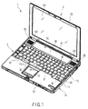
- FIG. 1 shows a portable computer 1 as an example of the electronic apparatus.
- the portable computer 1 comprises a main body unit 2 and a display unit 3.
- the main body unit 2 comprises a flat box-like housing 10. As shown in FIGS. 1, 2, and 3, the housing 10 comprises a lower housing 11 that essentially forms the lower half of the housing 10 and an upper housing 12, which essentially forms the upper half of the housing 10.
- a circuit board 13 is built inside the housing 10.
- the circuit board 13 is a system board, and includes electronic parts and the like thereon.
- the electronic parts on the circuit board 13 include a CPU to control the portable computer 1.
- the upper housing 12 that forms a portion of the housing 10 has a bottom wall 15 (hereinafter "wall").
- the wall 15 forms a part of a keyboard mounting portion 16.
- the wall 15 is formed so as to be forwardly inclined, that is, the front portion on the upper surface of the wall 15 is lower than the rear portion on the upper surface thereof. In other words, the wall 15 is tilted at an angle such that the front is lower than the back when the case 10 is mounted on a level surface.
- the upper housing 12 that includes the wall 15 may be formed of a light metal such as a magnesium alloy and the like, and is electrically conductive.
- the palm rest 20 which is formed by a portion of the upper housing 12 and an input device 21 such as a touch pad and the like are provided at the front of the main body unit 2.
- a battery storage portion 23 that stores a battery (not shown) as the power source is formed at the rear of the main body unit 2.
- Electronic parts such as speakers 24 and 25 are mounted at the rear of the main body unit 2.
- the keyboard 30 that is shown in FIG. 4 is mounted on the keyboard mounting portion 16 formed on the upper surface of the main body unit 2.
- the keyboard 30 is the drip-proof or waterproof type and has a cable 48 connected thereto as partially shown in FIG. 5.
- the cable 48 will be described hereinafter.
- engaging slots 31 for securing the keyboard 30 are formed at a plurality of locations in the width direction of the front of the upper housing 12.
- Convex portions 32 (shown in FIGS. 1, 4, and 6) which function as engagement portions with the engaging slots 31 are formed at the front end of the keyboard 30 at positions corresponding to the engaging slots 31.
- the convex portions 32 are formed at a plurality of locations at prescribed intervals in the width direction of the keyboard 30.
- the front end of the keyboard 30 is supported by the housing 10.
- Receiving portions 33 (shown in FIGS. 3 and 6), which may be engaged with the upper surface of the convex portion 32, are formed at the upper portion of the engaging slots 31.
- the receiving portions 33 protrude downward towards a portion of the upper housing 12.
- the keyboard 30 comprises the base 35 and the key tops 36.
- the convex portions 32 are formed at the front end of the base 35.
- a pair of right and left mounting portions 40 is formed at the rear end of keyboard 30.
- Keyboard support portions 41 are formed at positions corresponding to the mounting portions 40 on the upper case 12.
- a threaded hole 40a in each mounting portion 40 is formed, and the mounting portions 40 are fixed to the keyboard support portion 41 by fixing members 42 such as screw.
- the wall 15 of the upper housing 12 has a slight downward incline
- the front portion of the keyboard 30 that is mounted on the wall 15 is slightly lower than the rear portion thereof. Due to this slight downward incline, the operational characteristics of the keyboard 30 are improved. Furthermore, because of this incline, if liquid such as water spills on the keyboard 30, the liquid flows in the direction of the front end of the wall 15.
- openings 45 and 46 which open at the upper surface side are formed at a plurality of locations in the wall 15.
- the openings 45 and 46 expose a portion of the circuit board 13.
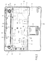
- the opening 45 which is positioned at the left front portion of the wall 15 exposes a circuit part, for example, connector 47, which forms the electrical connection between the keyboard 30 and the circuit board 13.
- the cable 48 (shown in FIG. 5) such as a flat cable or the like is connected to the connector 47. In this way, the cable 48 forms the electrical connection between the circuit board 13 and the keyboard 30.
- a "waterproof" sheet 50 which functions as a liquid impermeable sheet and is formed from a material that is substantially or completely impervious to liquid (i.e., substantially or completely prevents liquid from passing therethrough), is disposed between the wall 15 and the keyboard 30.
- the sheet 50 is wider in area than the keyboard 30 when viewed from the upper surface side such that it may cover the openings 45 and 46 of the wall 15 from above.
- a cable insertion portion 51 through which the cable 48 passes is formed in the sheet 50.
- the cable insertion portion 51 has a slit through which the cable 48 (see in FIG. 5) that is a flat cable or the like may be passed.
- the absorption member 52 that is made from a liquid absorptive material is provided around the cable insertion portion 51.
- the sheet 50 has an erect wall 53 positioned at one or more edges along a width of the sheet 50.
- the erect wall 53 is formed by folding an end portion of the sheet 50 in the upper direction, and prevents liquid on the surface of the sheet 50 from flowing from the edge portion of the sheet 50 to the outside. Also, because the front of the wall 15 slopes downward and erect walls 53 are formed at both sides of the sheet 50, liquid that spills onto the sheet 50 flows toward the front end of the sheet 50.
- an absorption member 54 made of a liquid absorptive material, as shown in FIG. 5, may be provided along a lengthwise edge of the sheet 50 so as to absorb liquid flowing downward on the sheet 50.
- a sheet-like insulator 55 formed from an electrically insulating material is arranged between the wall 15 of the upper housing 12 and the circuit board 13.
- the area of the insulator 55 is sufficient to cover the entire upper surface of the circuit board 13 with the exception of the openings 45 and 46.
- the insulator 55 prevents electrical shorting caused by contact between the conductive bottom wall 15 and the circuit board 13.
- the upper surface of the insulator 55 is fixed to the lower surface of the wall 15 by the both-sided adhesive tape 56.
- the front edge of the insulator 55 extends in the forward direction, and forms the waterproof portion 57.
- the waterproof portion 57 functions as a cover for the lower portion of the engaging slots 31 of the wall 15 inside the housing 10.
- the upper surface of the waterproof portion 57 is bonded to the edge portion of the lower wall 31a of the engaging slots 31 by the adhesive tape 56. Because of this structure, any liquid that enters the inner side of the engaging hole 31 does not leak in the downward direction.
- the lower wall 31a of the engaging hole 31 has an opening in order for the portion of the metal mold used when molding the receiving portions 33 to be removable in the vertical direction. For this reason, the lower end opening portion of the lower wall 31a which has an opening is covered by the waterproof portion 57 which is a portion of the insulator 55.
- the both-sided adhesive tape 56 which is provided at the waterproof portion 57 functions as a seal member for sealing the space between the lower wall 31a of the engaging hole 31 and the waterproof portion 57. Because the waterproof portion 57 covers the lower wall 31a of the engaging hole 31, a liquid storage portion 58 with a cross-sectional configuration like a bag with an open top is formed.
- front end of the sheet 50 may have a configuration such that the liquid on the sheet 50 is not prevented from flowing into the engaging hole 31.
- a part of the sheet 50, which is the position corresponding to the engaging hole 31 may have opening portions or notches.
- a concave portion 59 is formed at a portion of the front end portion of the wall 15, and the lower portion 21a of an input device 21 is inserted in the concave portion 59.
- Some of liquid on the sheet 50 may be led to the concave portion 59 because the liquid flows in the direction from the rear of the wall 15 to the front thereof. That is to say, the concave portion 59 may be used as a liquid storage portion.
- the main body unit 2 includes a cover member 60 provided on the upper surface side of the rear thereof.
- the cover member 60 is formed of a first cover 61 and a second cover 62.
- the first cover 61 comprises a main portion 65 and a sound emitting portion 66.
- the main portion 65 is a long and narrow configuration formed along the width direction of the main body unit 2 and has a length that may cover the battery storage portion 23.
- the cover member 60 covers the keyboard support portion 41.
- a plurality of fitting portions 72 is formed in the upper housing 12.
- the first cover 61 has sliding type engagement portions (not shown) at positions corresponding to these engagement portions 72. These engagement portions are configured so as to be engaged with the fitting portions 72 when the first cover 61 slides in the horizontal direction.
- Fit-in type engagement portions are formed on the back surface of the second cover 62.
- the engagement portions for the second cover 62 are configured such that they may fit into the receiving portions 73 formed on the upper housing 12.
- the cover member 60 comprising the first and second covers 61 and 62 is removable from the housing 10.
- the display unit 3 comprises a flat box-like case 100, a liquid crystal display panel (hereinafter "LCD") 101 provided in the case 100, a backlight (not shown) which is accommodated in the case 100, and the like.
- the display unit 3 is installed such that it may open and close in the vertical direction with respect to the main body unit 2 using the hinge portion 102 that is provided at the rear end side of the main body unit 2.
- the display unit 3 may rotate between the close position and the open position with respect to the main body unit 2.
- the image display screen of the LCD 101 is positioned downward and lies on top of the main body unit 2, while the upper surface of the main body unit 2 is covered from above by the display unit 3.
- the cover member 60 is then removed from the housing 10. After the fixing members 42 are removed from the mounting portion 40 of the rear end of the keyboard 30, the keyboard 30 is removed from the wall 15 by removing the convex portions 32 at the front end of the keyboard 30 from the engaging hole 31.
- FIGS. 8 and 9 show the state in which the keyboard 30 is removed.
- the liquid that has collected at the front portion or the concave portion 59 of the wall 15 is removed in this state. Also, the liquid that flows from the engaging hole 31 to the liquid storage portion 58 is also removed. Consequently, the main body unit 2 may be returned to a dry state.
- the sheet 50 which functions as a waterproof sheet and a waterproofing means which uses the engaging hole 31 for securing the keyboard 30
- liquid which spills on the keyboard 30 is prevented from reaching the circuit board 13, without making the structure of the housing 10 or the keyboard 30 itself complex.
- the water storage portion 58 is formed by using the waterproof portion 57 made by extending a portion of the front end of the insulator 55 to cover the lower end opening portion of the lower wall 31a of the engaging hole 31, a part of the insulator 55 which covers the circuit board 13 is used efficiently.
- the electronic apparatus in accordance with the invention is not limited to a portable computer. That is to say, the invention may be applied in a similar manner to any electronic apparatus which has a keyboard and has a circuit board inside a case.
Landscapes
- Engineering & Computer Science (AREA)
- Computer Hardware Design (AREA)
- Theoretical Computer Science (AREA)
- Physics & Mathematics (AREA)
- General Engineering & Computer Science (AREA)
- Human Computer Interaction (AREA)
- General Physics & Mathematics (AREA)
- Mathematical Physics (AREA)
- Input From Keyboards Or The Like (AREA)
- Casings For Electric Apparatus (AREA)
Abstract
According to one embodiment, an electronic apparatus with a keyboard (30) coupled to a cable (48), comprises a housing (10) including a wall (15) on which the keyboard (30) is mounted, the wall (15) including an opening (45), a circuit board (13) which is accommodated inside the housing (10), and to which the cable (48) is coupled through the opening (45), a sheet (50) which is arranged between the wall (15) and the keyboard (30), and which covers the opening (45), the sheet (50) including a cable insertion portion (51) through which the cable (48) is inserted.
Description
- One embodiment of the invention relates to an electronic apparatus with a keyboard such as a portable computer and the like.
- The main body of an electronic apparatus such as a portable computer has a housing that accommodates a circuit board and the like, and a keyboard is arranged on the upper part of the housing.
- In general, accidental spillage of liquids, for example water, to the main body causes problem, because there is the circuit board inside the housing. Therefore, to avoid such spilled liquid from reaching the circuit board, a waterproof measure is needed.
- United States Patent No. 6,610,944 (hereinafter "reference") discloses an electronic apparatus with such waterproof measure. The reference discloses the draining means that has a first drainage hole formed in the base of the keyboard, and a guide channel that has a second drainage hole formed in the lower surface of the base of the keyboard. Also, a third drainage hole that has a cover is formed below the second drainage hole.
- In the drainage means of the reference, because a plurality of dedicated drainage holes are formed in the main body or the keyboard, the configuration of the keyboard and the main body at those portions is complex and the metallic mold for molding is also complex. Furthermore, special consideration is given to the position of the drainage holes, and thus such architecture may cause the problem that the design freedom is limited.
- This invention provides an electronic apparatus with a keyboard coupled to a cable in which waterproofing can be improved.
- According to the invention, there is provided an electronic apparatus with a keyboard coupled to a cable, comprising:
- a housing including a wall on which the keyboard is mounted, the wall including an opening;
- a circuit board positioned inside the housing and coupled to the cable through the opening; and
- a sheet positioned between the wall and the keyboard and covering the opening, the sheet including a cable insertion portion through which the cable is inserted.
- According to this configuration, an electronic device is obtained in which waterproofing can be improved without making the structure of the keyboard and the like.
- This summary of the invention does not necessarily describe all necessary features so that the invention may also be a sub-combination of these described features.
- The invention can be more fully understood from the following detailed description when taken in conjunction with the accompanying drawings, in which:
- FIG. 1 is a perspective view of an exemplary portable computer according to an embodiment of the present invention;
- FIG. 2 is a plan view of an exemplary main body of the portable computer in a state where a keyboard and a cover have been removed according to the embodiment;
- FIG. 3 is a exemplary perspective view showing a portion of a housing according to the embodiment;
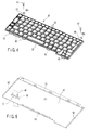
- FIG. 4 is a perspective view of the exemplary keyboard according to the embodiment;
- FIG. 5 is a perspective view of an exemplary sheet of the portable computer according to the embodiment;
- FIG. 6 is an exemplary sectional view cut off along a line F6-F6 in FIG. 1 according to the embodiment;
- FIG. 7 is an exemplary sectional view cut off along a line F7-F7 in FIG. 1 according to the embodiment;
- FIG. 8 is an exemplary sectional view cut off along a line F8-F8 in FIG. 2 according to the embodiment; and
- FIG. 9 is an exemplary sectional view cut off along a line F9-F9 in FIG. 2 according to the embodiment.
- Various embodiments according to the present invention will be described hereinafter with reference to the accompanying drawings. In general, according to one embodiment of the invention, an electronic apparatus with a keyboard coupled to a cable, comprises a housing including a wall on which the keyboard is mounted, the wall including an opening, a circuit board which is accommodated inside the housing, and to which the cable is coupled through the opening, a sheet which is arranged between the wall and the keyboard, and which covers the opening, the sheet including a cable insertion portion through which the cable is inserted.
- FIG. 1 shows a
portable computer 1 as an example of the electronic apparatus. Theportable computer 1 comprises amain body unit 2 and adisplay unit 3. - The
main body unit 2 comprises a flat box-like housing 10. As shown in FIGS. 1, 2, and 3, thehousing 10 comprises alower housing 11 that essentially forms the lower half of thehousing 10 and anupper housing 12, which essentially forms the upper half of thehousing 10. Acircuit board 13 is built inside thehousing 10. Thecircuit board 13 is a system board, and includes electronic parts and the like thereon. The electronic parts on thecircuit board 13 include a CPU to control theportable computer 1. - The
upper housing 12 that forms a portion of thehousing 10 has a bottom wall 15 (hereinafter "wall"). Thewall 15 forms a part of akeyboard mounting portion 16. Thewall 15 is formed so as to be forwardly inclined, that is, the front portion on the upper surface of thewall 15 is lower than the rear portion on the upper surface thereof. In other words, thewall 15 is tilted at an angle such that the front is lower than the back when thecase 10 is mounted on a level surface. Theupper housing 12 that includes thewall 15 may be formed of a light metal such as a magnesium alloy and the like, and is electrically conductive. - The
palm rest 20 which is formed by a portion of theupper housing 12 and aninput device 21 such as a touch pad and the like are provided at the front of themain body unit 2. Abattery storage portion 23 that stores a battery (not shown) as the power source is formed at the rear of themain body unit 2. Electronic parts such asspeakers main body unit 2. - The
keyboard 30 that is shown in FIG. 4 is mounted on thekeyboard mounting portion 16 formed on the upper surface of themain body unit 2. Thekeyboard 30 is the drip-proof or waterproof type and has acable 48 connected thereto as partially shown in FIG. 5. Thecable 48 will be described hereinafter. - As shown in FIGS. 2, 3, 6 and 8,
engaging slots 31 for securing thekeyboard 30 are formed at a plurality of locations in the width direction of the front of theupper housing 12. Convex portions 32 (shown in FIGS. 1, 4, and 6) which function as engagement portions with theengaging slots 31 are formed at the front end of thekeyboard 30 at positions corresponding to theengaging slots 31. Theconvex portions 32 are formed at a plurality of locations at prescribed intervals in the width direction of thekeyboard 30. - As shown in FIG. 6, by inserting the
convex portions 32 into theengaging slots 31 which correspond to the respectiveconvex portions 32, the front end of thekeyboard 30 is supported by thehousing 10. Receiving portions 33 (shown in FIGS. 3 and 6), which may be engaged with the upper surface of theconvex portion 32, are formed at the upper portion of theengaging slots 31. The receivingportions 33 protrude downward towards a portion of theupper housing 12. Thekeyboard 30 comprises thebase 35 and thekey tops 36. Theconvex portions 32 are formed at the front end of thebase 35. - As shown in FIG. 4, a pair of right and left mounting
portions 40 is formed at the rear end ofkeyboard 30.Keyboard support portions 41 are formed at positions corresponding to the mountingportions 40 on theupper case 12. A threadedhole 40a in eachmounting portion 40 is formed, and the mountingportions 40 are fixed to thekeyboard support portion 41 by fixingmembers 42 such as screw. - As described above, because the
wall 15 of theupper housing 12 has a slight downward incline, the front portion of thekeyboard 30 that is mounted on thewall 15 is slightly lower than the rear portion thereof. Due to this slight downward incline, the operational characteristics of thekeyboard 30 are improved. Furthermore, because of this incline, if liquid such as water spills on thekeyboard 30, the liquid flows in the direction of the front end of thewall 15. - As shown in FIGS. 2 and 3,
openings wall 15. Theopenings circuit board 13. Of theopenings opening 45 which is positioned at the left front portion of thewall 15 exposes a circuit part, for example,connector 47, which forms the electrical connection between thekeyboard 30 and thecircuit board 13. The cable 48 (shown in FIG. 5) such as a flat cable or the like is connected to theconnector 47. In this way, thecable 48 forms the electrical connection between thecircuit board 13 and thekeyboard 30. - A "waterproof"
sheet 50, as shown in FIG. 5, which functions as a liquid impermeable sheet and is formed from a material that is substantially or completely impervious to liquid (i.e., substantially or completely prevents liquid from passing therethrough), is disposed between thewall 15 and thekeyboard 30. Thesheet 50 is wider in area than thekeyboard 30 when viewed from the upper surface side such that it may cover theopenings wall 15 from above. Acable insertion portion 51 through which thecable 48 passes is formed in thesheet 50. - The
cable insertion portion 51 has a slit through which the cable 48 (see in FIG. 5) that is a flat cable or the like may be passed. Theabsorption member 52 that is made from a liquid absorptive material is provided around thecable insertion portion 51. - The
sheet 50 has anerect wall 53 positioned at one or more edges along a width of thesheet 50. Theerect wall 53 is formed by folding an end portion of thesheet 50 in the upper direction, and prevents liquid on the surface of thesheet 50 from flowing from the edge portion of thesheet 50 to the outside. Also, because the front of thewall 15 slopes downward anderect walls 53 are formed at both sides of thesheet 50, liquid that spills onto thesheet 50 flows toward the front end of thesheet 50. - It is to be noted that an
absorption member 54 made of a liquid absorptive material, as shown in FIG. 5, may be provided along a lengthwise edge of thesheet 50 so as to absorb liquid flowing downward on thesheet 50. - As shown in FIGS. 3, 6, and 8, a sheet-
like insulator 55 formed from an electrically insulating material is arranged between thewall 15 of theupper housing 12 and thecircuit board 13. The area of theinsulator 55 is sufficient to cover the entire upper surface of thecircuit board 13 with the exception of theopenings insulator 55 prevents electrical shorting caused by contact between theconductive bottom wall 15 and thecircuit board 13. The upper surface of theinsulator 55 is fixed to the lower surface of thewall 15 by the both-sidedadhesive tape 56. - The front edge of the
insulator 55 extends in the forward direction, and forms thewaterproof portion 57. Thewaterproof portion 57 functions as a cover for the lower portion of the engagingslots 31 of thewall 15 inside thehousing 10. The upper surface of thewaterproof portion 57 is bonded to the edge portion of thelower wall 31a of the engagingslots 31 by theadhesive tape 56. Because of this structure, any liquid that enters the inner side of the engaginghole 31 does not leak in the downward direction. - The
lower wall 31a of the engaginghole 31 has an opening in order for the portion of the metal mold used when molding the receivingportions 33 to be removable in the vertical direction. For this reason, the lower end opening portion of thelower wall 31a which has an opening is covered by thewaterproof portion 57 which is a portion of theinsulator 55. - The both-sided
adhesive tape 56 which is provided at thewaterproof portion 57 functions as a seal member for sealing the space between thelower wall 31a of the engaginghole 31 and thewaterproof portion 57. Because thewaterproof portion 57 covers thelower wall 31a of the engaginghole 31, aliquid storage portion 58 with a cross-sectional configuration like a bag with an open top is formed. - It is to be noted that front end of the
sheet 50 may have a configuration such that the liquid on thesheet 50 is not prevented from flowing into the engaginghole 31. For example, a part of thesheet 50, which is the position corresponding to the engaginghole 31, may have opening portions or notches. - As shown in FIGS. 3, 7 and 9, a
concave portion 59 is formed at a portion of the front end portion of thewall 15, and thelower portion 21a of aninput device 21 is inserted in theconcave portion 59. Some of liquid on thesheet 50 may be led to theconcave portion 59 because the liquid flows in the direction from the rear of thewall 15 to the front thereof. That is to say, theconcave portion 59 may be used as a liquid storage portion. - As shown in FIG. 1, the
main body unit 2 includes acover member 60 provided on the upper surface side of the rear thereof. Thecover member 60 is formed of afirst cover 61 and asecond cover 62. Thefirst cover 61 comprises amain portion 65 and asound emitting portion 66. Themain portion 65 is a long and narrow configuration formed along the width direction of themain body unit 2 and has a length that may cover thebattery storage portion 23. Thecover member 60 covers thekeyboard support portion 41. - As shown in FIG. 2, a plurality of
fitting portions 72 is formed in theupper housing 12. Thefirst cover 61 has sliding type engagement portions (not shown) at positions corresponding to theseengagement portions 72. These engagement portions are configured so as to be engaged with thefitting portions 72 when thefirst cover 61 slides in the horizontal direction. - Fit-in type engagement portions (not shown) are formed on the back surface of the
second cover 62. The engagement portions for thesecond cover 62 are configured such that they may fit into the receivingportions 73 formed on theupper housing 12. Thecover member 60 comprising the first and second covers 61 and 62 is removable from thehousing 10. - The
display unit 3 comprises a flat box-like case 100, a liquid crystal display panel (hereinafter "LCD") 101 provided in thecase 100, a backlight (not shown) which is accommodated in thecase 100, and the like. Thedisplay unit 3 is installed such that it may open and close in the vertical direction with respect to themain body unit 2 using thehinge portion 102 that is provided at the rear end side of themain body unit 2. - That is to say, the
display unit 3 may rotate between the close position and the open position with respect to themain body unit 2. When thedisplay unit 3 is closed, the image display screen of theLCD 101 is positioned downward and lies on top of themain body unit 2, while the upper surface of themain body unit 2 is covered from above by thedisplay unit 3. - The operation of the
portable computer 1 of this embodiment will be described in the following. - Assume that liquid such as water has accidentally spilled on the
keyboard 30. Because thekeyboard 30 is inclined such that the front portion is lower than the rear portion, the liquid that spills on thekeyboard 30 moves to the upper surface of thesheet 50 which functions as a waterproofing sheet and flows toward the front. Subsequently, some of the liquid enters theliquid storage portion 58 from the engaginghole 31. Some of the liquid may also enter theconcave portion 59. Furthermore, theabsorption member 52 may also absorb some of the liquid. Because theopenings wall 15 are covered by thesheet 50, liquid is prevented from entering thecircuit board 13. - If a liquid such as water spills on the
keyboard 30, an operator turns off the power while theportable computer 1 is kept in the horizontal state. Thecover member 60 is then removed from thehousing 10. After the fixingmembers 42 are removed from the mountingportion 40 of the rear end of thekeyboard 30, thekeyboard 30 is removed from thewall 15 by removing theconvex portions 32 at the front end of thekeyboard 30 from the engaginghole 31. - FIGS. 8 and 9 show the state in which the
keyboard 30 is removed. The liquid that has collected at the front portion or theconcave portion 59 of thewall 15 is removed in this state. Also, the liquid that flows from the engaginghole 31 to theliquid storage portion 58 is also removed. Consequently, themain body unit 2 may be returned to a dry state. - According to this embodiment, by providing the
sheet 50 which functions as a waterproof sheet and a waterproofing means which uses the engaginghole 31 for securing thekeyboard 30, liquid which spills on thekeyboard 30 is prevented from reaching thecircuit board 13, without making the structure of thehousing 10 or thekeyboard 30 itself complex. Also, because thewater storage portion 58 is formed by using thewaterproof portion 57 made by extending a portion of the front end of theinsulator 55 to cover the lower end opening portion of thelower wall 31a of the engaginghole 31, a part of theinsulator 55 which covers thecircuit board 13 is used efficiently. - It is to be noted that the electronic apparatus in accordance with the invention is not limited to a portable computer. That is to say, the invention may be applied in a similar manner to any electronic apparatus which has a keyboard and has a circuit board inside a case.
Claims (16)
- An electronic apparatus with a keyboard (30) coupled to a cable (48), characterized by comprising:a housing (10) including a wall (15) on which the keyboard (30) is mounted, the wall (15) including an opening (45) ;a circuit board (13) positioned inside the housing (10) and coupled to the cable (48) through the opening (45); anda sheet (50) positioned between the wall (15) and the keyboard (30) and covering the opening (45), the sheet (50) including a cable insertion portion (51) through which the cable (48) is inserted.
- The electronic apparatus according to claim 1, characterized in that the wall (15) includes an upper surface that is inclined when the housing (10) is mounted on a level surface so that a front top surface of the wall (15) is closer to the level surface than a top back surface of the wall (15).
- An electronic apparatus, characterized by comprising:a keyboard (30);a housing (10) including a wall (15) with an opening (45); anda liquid impermeable sheet (50) positioned between the wall (15) and the keyboard (30), the sheet (50) covering the opening (45) and including a portion (51) through which a first end of a cable (48) is inserted for coupling to the keyboard (30).
- The electronic apparatus according to claim 3, characterized by further comprising a circuit board (13) positioned inside the housing (10) and coupled to a second end of the cable (48).
- The electronic apparatus according to claim 3 or 4, characterized in that the wall (15) includes an upper surface that is inclined so that a front top surface of the wall (15) is positioned vertically higher than a top back surface of the wall (15).
- The electronic apparatus according to any one of claims 1 to 5, characterized by further comprising an absorption member (52) positioned around the cable insertion portion (51).
- The electronic apparatus according to any one of claims 1 to 6, the sheet (50) having an area wider than an area covered by the keyboard (30).
- The electronic apparatus according to any one of claims 1 to 7, characterized in that the sheet (50) includes one or more erect walls (53) positioned widthwise along edges of the sheet (50).
- The electronic apparatus according to any one of claims 1 to 8, characterized by further comprising an absorption member (54) positioned along a lengthwise edge of the sheet (50).
- An electronic apparatus, characterized by comprising:a housing (10) including a keyboard mounting portion (16) adapted to receive a keyboard (30), the housing (10) including at least one slot (31) provided in the keyboard mounting portion (16) to engage with the keyboard (30); anda waterproof portion (57) which covers the slot (31) of the housing (10).
- The electronic apparatus according to claim 10, characterized in that the housing (10) includes a wall (15) in the keyboard mounting portion (16), the wall (15) extending so that a front portion on an tipper surface of the wall (15) is lower than a rear portion on the tipper surface of the wall (15).
- The electronic apparatus according to claim 10 or 11, characterized by further comprising a sheet (50) arranged between the wall (15) and the keyboard (30).
- The electronic apparatus according to claim 10, 11 or 12, characterized in that the wall (15) is made of an electrically conductive material.
- The electronic apparatus according to claim 13, characterized by further comprising:a circuit board (13) arranged inside the housing (10); andan insulator (55), made of an electrically insulating material, arranged between a lower surface of the wall (15) and the circuit board (13).
- The electronic apparatus according to claim 14, characterized in that the waterproof portion (57) is apart of the insulator (55).
- The electronic apparatus according to claim 15, characterized in that an upper surface of the insulator (55) is fixed to the lower surface of the wall (15) by using both sided adhesive tape (56), and an upper surface of the waterproof portion (57) is adhered to the edge of the at least one slot (31) by using the adhesive tape (56).
Applications Claiming Priority (1)
| Application Number | Priority Date | Filing Date | Title |
|---|---|---|---|
| JP2004286464A JP2006099550A (en) | 2004-09-30 | 2004-09-30 | Electronics |
Publications (1)
| Publication Number | Publication Date |
|---|---|
| EP1645938A1 true EP1645938A1 (en) | 2006-04-12 |
Family
ID=35697131
Family Applications (1)
| Application Number | Title | Priority Date | Filing Date |
|---|---|---|---|
| EP05102125A Withdrawn EP1645938A1 (en) | 2004-09-30 | 2005-03-17 | Electronic apparatus with keyboard |
Country Status (4)
| Country | Link |
|---|---|
| US (2) | US7385808B2 (en) |
| EP (1) | EP1645938A1 (en) |
| JP (1) | JP2006099550A (en) |
| CN (2) | CN101101501B (en) |
Families Citing this family (31)
| Publication number | Priority date | Publication date | Assignee | Title |
|---|---|---|---|---|
| JP4130672B2 (en) * | 2005-07-29 | 2008-08-06 | 株式会社東芝 | Electronics |
| TWM291184U (en) * | 2005-12-16 | 2006-05-21 | Universal Scient Ind Co Ltd | Improved structure of touch-controlled panel for notebook computer |
| JP4933456B2 (en) * | 2006-01-12 | 2012-05-16 | 富士通株式会社 | Electronics |
| JP4220522B2 (en) * | 2006-01-13 | 2009-02-04 | 株式会社東芝 | Electronics |
| US20070235309A1 (en) * | 2006-04-11 | 2007-10-11 | Inventec Corporation | Waterproof structure of electronic device |
| JP4645533B2 (en) * | 2006-06-05 | 2011-03-09 | パナソニック株式会社 | Keyboard holding device for electronic equipment |
| JP4177862B2 (en) | 2006-07-20 | 2008-11-05 | 株式会社東芝 | Electronics |
| KR100925320B1 (en) * | 2006-12-01 | 2009-11-04 | 가시오게산키 가부시키가이샤 | Electronic device |
| US7784726B2 (en) * | 2006-12-31 | 2010-08-31 | Honda Motor Co., Ltd. | Multi-spool seatbelt retractor |
| US20080266905A1 (en) * | 2007-04-25 | 2008-10-30 | Jiun-Yi Yeh | Wire-guiding structure for a LED backlight module |
| CN101295197A (en) * | 2007-04-28 | 2008-10-29 | 佛山市顺德区顺达电脑厂有限公司 | Portable computer with drainage structure |
| TW200910156A (en) * | 2007-08-31 | 2009-03-01 | Chicony Electronic Co Ltd | A waterproof keyboard |
| TWM332217U (en) * | 2007-10-26 | 2008-05-11 | Wistron Corp | Electronic device |
| US7888607B2 (en) * | 2008-05-23 | 2011-02-15 | Changshu Sunrex Technology Co., Ltd. | Thin film circuit board device |
| JP4599437B2 (en) * | 2008-07-25 | 2010-12-15 | 株式会社東芝 | Electronics |
| CN101652036B (en) * | 2008-08-15 | 2012-07-04 | 鸿富锦精密工业(深圳)有限公司 | Electronic device |
| JP5213816B2 (en) * | 2008-09-04 | 2013-06-19 | パナソニック株式会社 | Lid opening / closing device and information processing device including the same |
| CN101968670A (en) * | 2009-07-27 | 2011-02-09 | 鸿富锦精密工业(深圳)有限公司 | All-in-one computer |
| JP2011048732A (en) * | 2009-08-28 | 2011-03-10 | Sony Corp | Electronic apparatus |
| TW201135776A (en) * | 2010-04-02 | 2011-10-16 | Shuttle Inc | Integral keyboard assembly |
| TWM408915U (en) * | 2011-01-21 | 2011-08-01 | Wistron Corp | electronic device |
| TWI442216B (en) * | 2011-07-06 | 2014-06-21 | Wistron Corp | Keyboard fixing structure for fixing a keyboard and portable electronic device |
| TWI435353B (en) * | 2011-08-24 | 2014-04-21 | Wistron Corp | Keyboard device with liquid expelling function and electronic module thereof |
| KR101281895B1 (en) * | 2011-08-24 | 2013-07-03 | 주식회사 팬택 | Fpc water-proofing structure |
| CN103034334B (en) * | 2011-09-30 | 2015-10-07 | 鸿富锦精密工业(武汉)有限公司 | Key panel fixer |
| US8693176B2 (en) * | 2012-02-28 | 2014-04-08 | Lenovo (Singapore) Pte. Ltd. | Smart drain hole |
| CN104656788A (en) * | 2013-11-22 | 2015-05-27 | 英业达科技有限公司 | Electronic device with waterproof structure |
| USD888714S1 (en) * | 2018-07-10 | 2020-06-30 | Getac Technology Corporation | Keyboard base for portable computer |
| JP7580021B2 (en) * | 2019-06-10 | 2024-11-11 | パナソニックIpマネジメント株式会社 | Information processing device |
| TWI817841B (en) * | 2022-11-23 | 2023-10-01 | 宏碁股份有限公司 | Body structure of portable computer |
| EP4455830B1 (en) * | 2023-04-25 | 2025-07-09 | LG Electronics Inc. | Display device |
Citations (4)
| Publication number | Priority date | Publication date | Assignee | Title |
|---|---|---|---|---|
| US20030129010A1 (en) * | 2002-01-04 | 2003-07-10 | Chicony Electronics Co., Ltd. | Keyboard with liquid-draining function |
| US6610944B2 (en) * | 2001-09-22 | 2003-08-26 | Lg Electronics Inc. | Keyboard with draining unit and notebook computer having the keyboard |
| US20030215277A1 (en) * | 2002-05-20 | 2003-11-20 | Dell Products L.P. | Keyboard deflection control |
| TW584239U (en) * | 2003-04-11 | 2004-04-11 | Hon Hai Prec Ind Co Ltd | Keyboard securing device |
Family Cites Families (35)
| Publication number | Priority date | Publication date | Assignee | Title |
|---|---|---|---|---|
| JPS5713537A (en) * | 1980-06-25 | 1982-01-23 | Ncr Co | Waterproof flat keyboard device |
| JPS6343223U (en) * | 1986-09-04 | 1988-03-23 | ||
| JPH0637464Y2 (en) * | 1988-08-17 | 1994-09-28 | 沖電気工業株式会社 | Keyboard device drip-proof structure |
| EP0374273A1 (en) * | 1988-12-17 | 1990-06-27 | Lexmark International, Inc. | PS/2-like keyboard protected against vandalism and spill |
| US5335141A (en) * | 1989-06-23 | 1994-08-02 | Kabushiki Kaisha Toshiba | Portable electronic apparatus having a removable keyboard secured to a housing by screws protruding through the bottom wall of the housing |
| JP2763137B2 (en) * | 1989-06-23 | 1998-06-11 | 株式会社東芝 | Keyboard unit and small electronic device equipped with the keyboard unit |
| JPH0553711A (en) | 1991-08-22 | 1993-03-05 | Ricoh Co Ltd | Keyboard layout sheet |
| JPH05210725A (en) | 1992-01-31 | 1993-08-20 | Furukawa Electric Co Ltd:The | Input display control method |
| JPH06187090A (en) | 1992-12-21 | 1994-07-08 | Ricoh Co Ltd | Graphic input device |
| US5689400A (en) * | 1994-05-31 | 1997-11-18 | Kabushiki Kaisha Toshiba | Portable electronic apparatus including space-saving component mounting features |
| US5421659A (en) * | 1994-09-07 | 1995-06-06 | Liang; Hui-Hu | Keyboard housing with channels for draining spilled liquid |
| JP3258198B2 (en) | 1995-04-28 | 2002-02-18 | 株式会社東芝 | Cooling device for circuit module and portable electronic device having this cooling device |
| JP3297251B2 (en) | 1995-06-20 | 2002-07-02 | 株式会社東芝 | Portable electronic devices |
| JP3382073B2 (en) * | 1995-09-19 | 2003-03-04 | 株式会社東芝 | Portable electronic devices |
| CN2327005Y (en) * | 1997-11-25 | 1999-06-30 | 明碁电脑股份有限公司 | waterproof keyboard |
| JPH11175186A (en) * | 1997-12-17 | 1999-07-02 | Toshiba Corp | Portable information device with removable keyboard |
| KR100345875B1 (en) * | 1998-09-14 | 2002-10-25 | 삼성전자 주식회사 | A portable computer |
| US6156983A (en) * | 1999-04-01 | 2000-12-05 | Chicony Electronics Co., Ltd. | Water-proof keyboard |
| JP2001228950A (en) * | 2000-02-17 | 2001-08-24 | Matsushita Electric Ind Co Ltd | Waterproof mechanism for information equipment |
| US6317314B1 (en) * | 2000-03-13 | 2001-11-13 | Compal Electronics, Inc. | Reinforced housing for a module of a portable computer |
| US6443644B1 (en) * | 2000-03-17 | 2002-09-03 | Minebea Co., Ltd. | Spill resistant keyboard |
| US6716518B2 (en) * | 2000-04-12 | 2004-04-06 | International Business Machines Corporation | Method and system for absorbent sponge membrane for spill protection in electronic devices |
| US6398436B1 (en) * | 2000-04-12 | 2002-06-04 | International Business Machines Corporation | Spill protection for electronic devices |
| CN2438156Y (en) * | 2000-06-09 | 2001-07-04 | 华硕电脑股份有限公司 | Waterproof device for laptop |
| US6542355B1 (en) * | 2000-09-29 | 2003-04-01 | Silitek Corporation | Waterproof keyboard |
| JP2002352659A (en) * | 2001-05-29 | 2002-12-06 | Hosiden Corp | Keyboard and assembly structure for keyboard |
| US6803865B2 (en) * | 2001-08-14 | 2004-10-12 | Hewlett-Packard Development Company, L.P. | Spill-resistant keyboard |
| TW592327U (en) * | 2001-09-10 | 2004-06-11 | Wistron Corp | Data processing device with liquid diversion structure |
| JP2003272469A (en) * | 2002-03-19 | 2003-09-26 | Minebea Co Ltd | Waterproof mechanism of keyboard |
| US6860660B2 (en) * | 2002-04-17 | 2005-03-01 | Preh-Werke Gmbh & Co. Kg | Keyboard, preferably for electronic payment terminals |
| US6641317B1 (en) * | 2002-04-18 | 2003-11-04 | Behavior Tech Computer Corporation | Draining structure for a keyboard |
| JP4072723B2 (en) | 2003-03-19 | 2008-04-09 | 清水建設株式会社 | Bender element installation frame |
| US20040226248A1 (en) * | 2003-05-16 | 2004-11-18 | Wu Lee Hong | Type of splash-resistant modular keyboard for computers |
| JP2005070970A (en) * | 2003-08-21 | 2005-03-17 | Toshiba Corp | Electronics |
| JP2005070969A (en) * | 2003-08-21 | 2005-03-17 | Toshiba Corp | Electronic device and operation unit used for electronic device |
-
2004
- 2004-09-30 JP JP2004286464A patent/JP2006099550A/en active Pending
-
2005
- 2005-03-04 US US11/072,601 patent/US7385808B2/en not_active Expired - Lifetime
- 2005-03-17 EP EP05102125A patent/EP1645938A1/en not_active Withdrawn
- 2005-04-26 CN CN2007101427998A patent/CN101101501B/en not_active Expired - Lifetime
- 2005-04-26 CN CNB2005100668061A patent/CN100397290C/en not_active Expired - Lifetime
-
2008
- 2008-03-17 US US12/050,039 patent/US7535699B2/en not_active Expired - Lifetime
Patent Citations (5)
| Publication number | Priority date | Publication date | Assignee | Title |
|---|---|---|---|---|
| US6610944B2 (en) * | 2001-09-22 | 2003-08-26 | Lg Electronics Inc. | Keyboard with draining unit and notebook computer having the keyboard |
| US20030129010A1 (en) * | 2002-01-04 | 2003-07-10 | Chicony Electronics Co., Ltd. | Keyboard with liquid-draining function |
| US20030215277A1 (en) * | 2002-05-20 | 2003-11-20 | Dell Products L.P. | Keyboard deflection control |
| TW584239U (en) * | 2003-04-11 | 2004-04-11 | Hon Hai Prec Ind Co Ltd | Keyboard securing device |
| US20040201974A1 (en) * | 2003-04-11 | 2004-10-14 | Yu Weiming | Keyboard mounting system |
Also Published As
| Publication number | Publication date |
|---|---|
| US7535699B2 (en) | 2009-05-19 |
| JP2006099550A (en) | 2006-04-13 |
| US20080165477A1 (en) | 2008-07-10 |
| US20060067035A1 (en) | 2006-03-30 |
| CN101101501B (en) | 2010-06-02 |
| CN1755579A (en) | 2006-04-05 |
| US7385808B2 (en) | 2008-06-10 |
| CN100397290C (en) | 2008-06-25 |
| CN101101501A (en) | 2008-01-09 |
Similar Documents
| Publication | Publication Date | Title |
|---|---|---|
| US7535699B2 (en) | Electronic apparatus with keyboard | |
| US7710716B2 (en) | Electronic apparatus | |
| US7838784B2 (en) | Electronic apparatus having a housing having a liquid drain structure | |
| US7723624B2 (en) | Electronic apparatus | |
| JP4703308B2 (en) | Electronics | |
| US7684177B2 (en) | Electronic apparatus | |
| US7738239B2 (en) | Electronic apparatus | |
| KR920001298A (en) | Portable electronics with contact terminals in electrical contact with the battery | |
| KR920001297A (en) | Portable electronics with removable batteries and optional components to expand functionality | |
| WO2007013672A1 (en) | Electronic device and casing used therefor | |
| JPH09242852A (en) | Shift lever device | |
| JP2008269647A (en) | Electronics | |
| US6525927B1 (en) | Folding electronic apparatus | |
| JP2008009904A (en) | Electronic device | |
| CN215474492U (en) | Vehicle control device and vehicle | |
| JP4227148B2 (en) | Electronics | |
| JP3292106B2 (en) | Fixing structure of mounting clip | |
| JP2007280278A (en) | Electronics | |
| JP2000137768A (en) | Ic card processor | |
| JP2008269475A (en) | Expansion device and electronic device |
Legal Events
| Date | Code | Title | Description |
|---|---|---|---|
| PUAI | Public reference made under article 153(3) epc to a published international application that has entered the european phase |
Free format text: ORIGINAL CODE: 0009012 |
|
| 17P | Request for examination filed |
Effective date: 20050318 |
|
| AK | Designated contracting states |
Kind code of ref document: A1 Designated state(s): AT BE BG CH CY CZ DE DK EE ES FI FR GB GR HU IE IS IT LI LT LU MC NL PL PT RO SE SI SK TR |
|
| AX | Request for extension of the european patent |
Extension state: AL BA HR LV MK YU |
|
| AKX | Designation fees paid |
Designated state(s): DE FR GB |
|
| STAA | Information on the status of an ep patent application or granted ep patent |
Free format text: STATUS: THE APPLICATION HAS BEEN WITHDRAWN |
|
| 18W | Application withdrawn |
Effective date: 20100611 |