EP1645747B1 - Adjustable nozzle for a solid-propellant engine, and engine featuring such an adjustable nozzle - Google Patents
Adjustable nozzle for a solid-propellant engine, and engine featuring such an adjustable nozzle Download PDFInfo
- Publication number
- EP1645747B1 EP1645747B1 EP20050109166 EP05109166A EP1645747B1 EP 1645747 B1 EP1645747 B1 EP 1645747B1 EP 20050109166 EP20050109166 EP 20050109166 EP 05109166 A EP05109166 A EP 05109166A EP 1645747 B1 EP1645747 B1 EP 1645747B1
- Authority
- EP
- European Patent Office
- Prior art keywords
- nozzle
- choke
- wearable
- controlled
- wear
- Prior art date
- Legal status (The legal status is an assumption and is not a legal conclusion. Google has not performed a legal analysis and makes no representation as to the accuracy of the status listed.)
- Expired - Lifetime
Links
Images

Classifications
-
- F—MECHANICAL ENGINEERING; LIGHTING; HEATING; WEAPONS; BLASTING
- F02—COMBUSTION ENGINES; HOT-GAS OR COMBUSTION-PRODUCT ENGINE PLANTS
- F02K—JET-PROPULSION PLANTS
- F02K9/00—Rocket-engine plants, i.e. plants carrying both fuel and oxidant therefor; Control thereof
- F02K9/08—Rocket-engine plants, i.e. plants carrying both fuel and oxidant therefor; Control thereof using solid propellants
- F02K9/10—Shape or structure of solid propellant charges
-
- F—MECHANICAL ENGINEERING; LIGHTING; HEATING; WEAPONS; BLASTING
- F02—COMBUSTION ENGINES; HOT-GAS OR COMBUSTION-PRODUCT ENGINE PLANTS
- F02K—JET-PROPULSION PLANTS
- F02K9/00—Rocket-engine plants, i.e. plants carrying both fuel and oxidant therefor; Control thereof
- F02K9/08—Rocket-engine plants, i.e. plants carrying both fuel and oxidant therefor; Control thereof using solid propellants
- F02K9/26—Burning control
-
- F—MECHANICAL ENGINEERING; LIGHTING; HEATING; WEAPONS; BLASTING
- F02—COMBUSTION ENGINES; HOT-GAS OR COMBUSTION-PRODUCT ENGINE PLANTS
- F02K—JET-PROPULSION PLANTS
- F02K9/00—Rocket-engine plants, i.e. plants carrying both fuel and oxidant therefor; Control thereof
- F02K9/80—Rocket-engine plants, i.e. plants carrying both fuel and oxidant therefor; Control thereof characterised by thrust or thrust vector control
- F02K9/86—Rocket-engine plants, i.e. plants carrying both fuel and oxidant therefor; Control thereof characterised by thrust or thrust vector control using nozzle throats of adjustable cross- section
-
- F—MECHANICAL ENGINEERING; LIGHTING; HEATING; WEAPONS; BLASTING
- F05—INDEXING SCHEMES RELATING TO ENGINES OR PUMPS IN VARIOUS SUBCLASSES OF CLASSES F01-F04
- F05D—INDEXING SCHEME FOR ASPECTS RELATING TO NON-POSITIVE-DISPLACEMENT MACHINES OR ENGINES, GAS-TURBINES OR JET-PROPULSION PLANTS
- F05D2260/00—Function
- F05D2260/30—Retaining components in desired mutual position
Definitions
- the present invention relates to an adjustable nozzle for a solid-propellant engine.
- a solid-propellant engine comprises an outer casing housing the solid propellant and defining a propellant combustion chamber; a propellant ignition device; and an exhaust nozzle for accelerating the combustion gases to produce the desired propulsive thrust.
- nozzles with a variable throat diameter are known to be used, wherein the throat diameter is varied by a mechanical adjusting device comprising a choke sleeve movable, inside the gas exhaust conduit, between a withdrawn rest position extending outside the conduit, and a forward work position extending at least partly inside the exhaust conduit to reduce the gas flow section.
- the sleeve is moved between the work and rest positions by an actuator assembly located outside the nozzle and connected mechanically to the sleeve through an opening formed through a lateral wall of the nozzle.
- Adjustable nozzles for a solid-propellant engines in which for varying a reference section comprise a block of propellant material are disclosed in US-A-3 182 447 and US-A-4 478 040 .
- an adjustable nozzle for a solid-propellant engine as claimed in Claim 1.
- the nozzle comprises a wearable, controlled-wear body that is a thermally wearable body conveniently comprising a block of propellant material.
- the wearable body is also preferably selectable from a number of bodies of different wear rates.
- the present invention also relates to a solid-propellant engine.
- a solid-propellant engine comprising an outer casing, a first block of propellant material housed in said casing, and an adjustable nozzle; as claimed in claim 1.
- Number 1 in Figure 1 indicates as a whole a solid-propellant engine for a rocket (not shown).
- Engine 1 comprises an outer casing 2 having a respective axis 3 of symmetry and defining a chamber 4 for housing solid propellant 5.
- the engine also comprises an adjustable or variable-throat exhaust nozzle 6 fitted to an axial end of casing 2 to accelerate the combustion gases and produce the desired propulsive thrust.
- Tubular body 8 also comprises a radial connecting flange 13 connected in known manner to casing 2 and bounded by a flat radial annular surface 14 perpendicular to axis 3 and connected to inlet portion 11 by a convex surface 15.
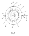
- nozzle 6 also comprises a choke device 16 housed entirely inside casing 2, and in turn comprising a disk-shaped body 18 ( Figure 2 ), which is conveniently made of graphitic material, is coaxial with axis 3, and comprises a central hollow tubular choke portion 19, which fits inside inlet portion 11 to reduce the gas flow section, and an outer radial flange 20 facing and detached from surface 14.
- Flange 20 has a number of intermediate circumferential gas-flow slits 21; and a peripheral annular portion 22 resting against one end of a tubular cartridge 5a of solid propellant.
- disk-shaped body 18 When engine 1 is turned on, disk-shaped body 18 is maintained in a withdrawn rest position (shown by the continuous line in Figure 1 ) wherein portion 22 of flange 20 is forced into contact with the end of propellant cartridge 5a by a wearable, controlled-wear, cylindrical tubular body 25 coaxial with axis 3 and located upstream from conduit 10 in the gas outflow direction. More specifically, body 25 surrounds portion 19 and extends between surface 14 and flange 20, which is thus gripped between body 25 and cartridge 5a and so clamped in an axially-fixed position with respect to body 6.
- Body 25 is conveniently made of the same propellant material as cartridge 5a. Alternatively, body 25 is selectable from a number of tubular bodies of different thickness S ( Figure 1 ) to vary the instant in which nozzle 6 is choked.
- disk-shaped body 18 is provided with a layer 30 ( Figure 1 ) of damping material, which is deformed elastically between disk-shaped body 18 and surface 14 when disk-shaped body 18 is in the forward work position.
- Guide device 27 ensures disk-shaped body 18 moves smoothly towards body 8 with no jamming, which would result in an unpredictable, totally unacceptable change in the instant in which the throat diameter of the nozzle is reduced.
- layer 30 of damping material ensures gradual engagement with no shock or vibration.
- controlling the position of disk-shaped choke body 18 using a straightforward wearable body housed inside a chamber communicating directly with the propellant combustion chamber greatly simplifies manufacture of nozzle 6 and makes it more reliable, by eliminating the need for openings in the lateral wall of the nozzle, and also for seals necessarily required for the openings in known solutions.
- nozzle 6 is also much easier to produce and much more reliable by featuring no mechanical actuators requiring protection against thermal and mechanical stress induced by combustion of the propellant.
- nozzle 6 as described herein without, however, departing from the protective scope defined in the accompanying Claims.
- the disk-shaped body may be formed differently from the one described by way of example, and using materials other than those described; and changes may also be made to the geometry and location of the retaining body of wearable material.
- the nozzle need not have a layer 30 of damping material; and layer 30 may be carried by body 8.
Landscapes
- Engineering & Computer Science (AREA)
- Chemical & Material Sciences (AREA)
- Combustion & Propulsion (AREA)
- Mechanical Engineering (AREA)
- General Engineering & Computer Science (AREA)
- Supercharger (AREA)
- Jet Pumps And Other Pumps (AREA)
- Nozzles (AREA)
- Means For Warming Up And Starting Carburetors (AREA)
- Fuel-Injection Apparatus (AREA)
Description
- The present invention relates to an adjustable nozzle for a solid-propellant engine.
- As is known, a solid-propellant engine comprises an outer casing housing the solid propellant and defining a propellant combustion chamber; a propellant ignition device; and an exhaust nozzle for accelerating the combustion gases to produce the desired propulsive thrust.
- To vary the thrust with time to achieve the desired thrust or mission profile, nozzles with a variable throat diameter are known to be used, wherein the throat diameter is varied by a mechanical adjusting device comprising a choke sleeve movable, inside the gas exhaust conduit, between a withdrawn rest position extending outside the conduit, and a forward work position extending at least partly inside the exhaust conduit to reduce the gas flow section. The sleeve is moved between the work and rest positions by an actuator assembly located outside the nozzle and connected mechanically to the sleeve through an opening formed through a lateral wall of the nozzle.
- Though widely used, known nozzles of the type described above are unreliable and inefficient, despite being complex in design and expensive to produce.
- This is mainly due to employing an external mechanical actuator, operation and mechanical connection of which to the sleeve through the opening are particularly awkward and often impaired by the high temperature - about 3700 kelvins - in the conduit, and by the fluid-dynamic stress transmitted directly by the exhaust gases.
- Adjustable nozzles for a solid-propellant engines in which for varying a reference section comprise a block of propellant material are disclosed in
US-A-3 182 447 andUS-A-4 478 040 . - It is an object of the present invention to provide an adjustable nozzle designed to provide a straightforward solution to the above problems, and which, at the same time, is cheap and easy to produce and highly reliable and efficient.
- According to the present invention, there is provided an adjustable nozzle for a solid-propellant engine, as claimed in Claim 1.
- In particular, the nozzle comprises a wearable, controlled-wear body that is a thermally wearable body conveniently comprising a block of propellant material. The wearable body is also preferably selectable from a number of bodies of different wear rates.
- The present invention also relates to a solid-propellant engine.
- According to the present invention, there is provided a solid-propellant engine comprising an outer casing, a first block of propellant material housed in said casing, and an adjustable nozzle; as claimed in claim 1.
- A non-limiting embodiment of the invention will be described by way of example with reference to the accompanying drawings, in which:
-
Figure 1 shows a schematic, partly sectioned view of a solid-propellant engine featuring an adjustable nozzle in accordance with the teachings of the present invention; -
Figure 2 shows a larger-scale view in perspective of a detail inFigure 1 . - Number 1 in
Figure 1 indicates as a whole a solid-propellant engine for a rocket (not shown). Engine 1 comprises anouter casing 2 having a respective axis 3 of symmetry and defining a chamber 4 for housingsolid propellant 5. The engine also comprises an adjustable or variable-throat exhaust nozzle 6 fitted to an axial end ofcasing 2 to accelerate the combustion gases and produce the desired propulsive thrust. - With reference to
Figure 1 , nozzle 6 comprises a gas-conductingtubular body 8 connected in known manner tocasing 2, and in turn comprising atubular portion 9 extending coaxially with axis 3 and defining agas exhaust conduit 10.Conduit 10 comprises a substantiallycylindrical inlet portion 11 defining a reference flow section of a given diameter D1 normally referred to as the initial throat or reference diameter; and anoutlet portion 12 diverging towards the free end oftubular body 8. -
Tubular body 8 also comprises a radial connectingflange 13 connected in known manner tocasing 2 and bounded by a flat radialannular surface 14 perpendicular to axis 3 and connected toinlet portion 11 by aconvex surface 15. - With reference to
Figure 1 , nozzle 6 also comprises achoke device 16 housed entirely insidecasing 2, and in turn comprising a disk-shaped body 18 (Figure 2 ), which is conveniently made of graphitic material, is coaxial with axis 3, and comprises a central hollowtubular choke portion 19, which fits insideinlet portion 11 to reduce the gas flow section, and an outerradial flange 20 facing and detached fromsurface 14.Flange 20 has a number of intermediate circumferential gas-flow slits 21; and a peripheralannular portion 22 resting against one end of atubular cartridge 5a of solid propellant. - When engine 1 is turned on, disk-
shaped body 18 is maintained in a withdrawn rest position (shown by the continuous line inFigure 1 ) whereinportion 22 offlange 20 is forced into contact with the end ofpropellant cartridge 5a by a wearable, controlled-wear, cylindricaltubular body 25 coaxial with axis 3 and located upstream fromconduit 10 in the gas outflow direction. More specifically,body 25 surroundsportion 19 and extends betweensurface 14 andflange 20, which is thus gripped betweenbody 25 andcartridge 5a and so clamped in an axially-fixed position with respect to body 6.Body 25 is conveniently made of the same propellant material ascartridge 5a. Alternatively,body 25 is selectable from a number of tubular bodies of different thickness S (Figure 1 ) to vary the instant in which nozzle 6 is choked. - Once the engine is turned on,
propellant slits 21 and chokeportion 19 to nozzle 6, and then alongconduit 10. Disk-shaped body 18 being clamped in the rest position, nozzle 6 operates with throat diameter D1. Once the engine is turned on,body 25 also begins to gradually wear down radially at a rate depending on the material and geometry of the body, and for a time depending on the material used and thickness S. Oncebody 25 is completely worn down, the dynamic thrust generated by the gases pushes disk-shaped body 18 towardsbody 8 into a forward work position, in whichportion 19 is inserted insideportion 11, thus reducing the flow section and the throat of the nozzle to a diameter D2 smaller than D1, as shown by the dash line inFigure 1 . - Disk-
shaped body 18 is guided from the withdrawn rest position to the forward work position by aguide device 27 comprising a number of fixed,straight guide rods 28, which are connected integrally tocasing 2 orbody 8, are parallel to axis 3, and are spaced along the outer periphery of disk-shaped body 18. Eachrod 28 slides inside a respective radial recess 29 (Figure 2 ) formed onperipheral portion 22 offlange 20, to connect disk-shaped body 18 tocasing 2 in axially-sliding, angularly-fixed manner. - To cushion the impact of disk-
shaped body 18 againstbody 8, disk-shaped body 18 is provided with a layer 30 (Figure 1 ) of damping material, which is deformed elastically between disk-shaped body 18 andsurface 14 when disk-shaped body 18 is in the forward work position. - As will be clear from the foregoing description, variable-throat nozzle 6 is highly reliable and efficient, while at the same time being cheap and easy to produce. Unlike known solutions, in fact, as opposed to an external actuator, the position of
choke portion 19 is controlled by a straightforward inner retaining body, which wears down gradually from the instant the engine is turned on. Control of the instant in which the nozzle is choked, i.e. in which the throat diameter is reduced, is equally straightforward; which instant, as stated, is determined simply by appropriately selecting the type of material and/or the geometrical/dimensional characteristics of the body. -
Guide device 27 ensures disk-shaped body 18 moves smoothly towardsbody 8 with no jamming, which would result in an unpredictable, totally unacceptable change in the instant in which the throat diameter of the nozzle is reduced. - Finally,
layer 30 of damping material ensures gradual engagement with no shock or vibration. - As will be clear from the foregoing description, controlling the position of disk-
shaped choke body 18 using a straightforward wearable body housed inside a chamber communicating directly with the propellant combustion chamber greatly simplifies manufacture of nozzle 6 and makes it more reliable, by eliminating the need for openings in the lateral wall of the nozzle, and also for seals necessarily required for the openings in known solutions. With respect to known solutions, nozzle 6 is also much easier to produce and much more reliable by featuring no mechanical actuators requiring protection against thermal and mechanical stress induced by combustion of the propellant. - Clearly, changes may be made to nozzle 6 as described herein without, however, departing from the protective scope defined in the accompanying Claims. In particular, the disk-shaped body may be formed differently from the one described by way of example, and using materials other than those described; and changes may also be made to the geometry and location of the retaining body of wearable material.
- Finally, the nozzle need not have a
layer 30 of damping material; andlayer 30 may be carried bybody 8.
Claims (14)
- An adjustable nozzle (6) for a solid-propellant engine (1), the nozzle (6) comprising a conducting body (8) defining a conduit (10) for conducting the gases produced by combustion of a solid propellant and having a reference section (11); and choke means (16) for varying said reference section (11) and comprising a choke body (18) movable with respect to said conducting body (8); characterized in that said choke means (16) also comprise a wearable, controlled-wear body (25) interposed between said conducting body (8) and said choke body (18) for maintaining the choke body (18) in a rest condition, and allowing movement of the choke body (18) into at least one choke position choking said reference section (11) after a predetermined time and wherein said wearable, controlled-wear body (25) comprises a block (25) of propellant material.
- A nozzle as claimed in Claim 1, characterized in that said wearable, controlled-wear body (25) is a thermally wearable body.
- A nozzle as claimed in one of Claims 1 or 2, characterized in that said wearable, controlled-wear body is selectable from a number of bodies of different wear rates.
- A nozzle as claimed in any one of the foregoing Claims, characterized in that said choke body rests directly on said wearable, controlled-wear body (25).
- A nozzle as claimed in any one of the foregoing Claims, characterized in that said wearable, controlled-wear body (25) is located upstream from said conduit (10) in the flow direction of said gases.
- A nozzle as claimed in any one of Claims 1 to 5, characterized in that said wearable, controlled-wear body (25) is an annular body at least partly surrounding said choke body (18).
- A nozzle as claimed in any one of the foregoing Claims, characterized in that said choke body (18) comprises a radial flange (20); said wearable, controlled-wear body (25) acting on a peripheral portion (22) of said radial flange (20) to retain said choke body (18) in said rest condition.
- A nozzle as claimed in one of the foregoing Claims, characterized by comprising connecting means (27) for connecting said wearable, controlled-wear body (25) to said conducting body (8) in sliding manner in a direction (3) parallel to the outflow direction of said gases and in an angularly-fixed position.
- A nozzle as claimed in Claim 8, characterized in that said connecting means comprise guide bars (28) fixed with respect to said conducting body (8) and engaging respective seats (29) in said radial flange (20).
- A nozzle as claimed in any one of the foregoing Claims, characterized by comprising damping means (30) interposed between said choke body (18) and said conducting body (8).
- A nozzle as claimed in Claim 10 characterized in that said damping means are carried by said choke body (18).
- A solid-propellant engine (1) comprising an outer casing (2), a first block of propellant material (5a) housed in said casing (2), and an adjustable nozzle (6) ; as defined in claim 1.
- engine as claimed in claim 12, characterized in that said first block of propellant material, said wearable, controlled-wear body (25) and said choke body (18) are housed entirely inside said casing (2) when the choke body is in said rest condition.
- An engine as claimed in Claim 13, characterized in that said choke body (18) is gripped between said first block of propellant material (5a) and said wearable controlled-wear body (25).
Applications Claiming Priority (1)
| Application Number | Priority Date | Filing Date | Title |
|---|---|---|---|
| ITTO20040670 ITTO20040670A1 (en) | 2004-10-05 | 2004-10-05 | ADJUSTABLE NOZZLE OF A MOTOR WITH A PROPELLENT SOLID AND MOTOR PROVIDED WITH SUCH ADJUSTABLE NOZZLE |
Publications (3)
| Publication Number | Publication Date |
|---|---|
| EP1645747A2 EP1645747A2 (en) | 2006-04-12 |
| EP1645747A3 EP1645747A3 (en) | 2006-11-22 |
| EP1645747B1 true EP1645747B1 (en) | 2011-05-04 |
Family
ID=35058577
Family Applications (1)
| Application Number | Title | Priority Date | Filing Date |
|---|---|---|---|
| EP20050109166 Expired - Lifetime EP1645747B1 (en) | 2004-10-05 | 2005-10-04 | Adjustable nozzle for a solid-propellant engine, and engine featuring such an adjustable nozzle |
Country Status (4)
| Country | Link |
|---|---|
| EP (1) | EP1645747B1 (en) |
| DE (1) | DE602005027787D1 (en) |
| IT (1) | ITTO20040670A1 (en) |
| NO (1) | NO337371B1 (en) |
Families Citing this family (2)
| Publication number | Priority date | Publication date | Assignee | Title |
|---|---|---|---|---|
| FR2993927B1 (en) | 2012-07-27 | 2014-08-22 | Snecma | PIECE FOR MODIFYING THE PROFILE OF AERODYNAMIC VEIN |
| CN110455862A (en) * | 2019-08-19 | 2019-11-15 | 宜宾北方川安化工有限公司 | A method of adjusting civilian SOLID PROPELLANT COMBUSTION performance |
Family Cites Families (5)
| Publication number | Priority date | Publication date | Assignee | Title |
|---|---|---|---|---|
| US3182447A (en) * | 1957-02-27 | 1965-05-11 | Thiokol Chemical Corp | Reaction motor |
| US3914935A (en) * | 1969-03-17 | 1975-10-28 | Rockwell International Corp | Dual area nozzle |
| US3943708A (en) * | 1973-11-26 | 1976-03-16 | The United States Of America As Represented By The Secretary Of The Navy | Two area rocket nozzle |
| US4478040A (en) * | 1982-09-28 | 1984-10-23 | Thiokol Corporation | Dual area nozzle actuating mechanical actuation system |
| US5435128A (en) * | 1993-11-15 | 1995-07-25 | Thiokol Corporation | Pyrotechnically driven nozzle restrictor |
-
2004
- 2004-10-05 IT ITTO20040670 patent/ITTO20040670A1/en unknown
-
2005
- 2005-10-03 NO NO20054531A patent/NO337371B1/en unknown
- 2005-10-04 EP EP20050109166 patent/EP1645747B1/en not_active Expired - Lifetime
- 2005-10-04 DE DE200560027787 patent/DE602005027787D1/en not_active Expired - Lifetime
Also Published As
| Publication number | Publication date |
|---|---|
| NO20054531L (en) | 2006-04-06 |
| DE602005027787D1 (en) | 2011-06-16 |
| ITTO20040670A1 (en) | 2005-01-05 |
| EP1645747A3 (en) | 2006-11-22 |
| NO20054531D0 (en) | 2005-10-03 |
| NO337371B1 (en) | 2016-03-29 |
| EP1645747A2 (en) | 2006-04-12 |
Similar Documents
| Publication | Publication Date | Title |
|---|---|---|
| US8215097B2 (en) | Rocket thruster assembly comprising load-balanced pintle valve | |
| JP5016052B2 (en) | Pintle control propulsion system with external dynamic seal | |
| EP3336429B1 (en) | An injector for a gas turbine | |
| AU2017387526B2 (en) | Electrically operated propellant for solid rocket motor thrust management | |
| US20090211225A1 (en) | Systems and methods for varying the thrust of rocket motors and engines while maintaining higher efficiency using moveable plug nozzles | |
| EP2818666B1 (en) | Turbocharger with turbine nozzle vanes and an annular rotary bypass valve | |
| EP2315928B1 (en) | Thrust vectoring apparatus for a jet engine, corresponding jet engine, thrust vectoring method and upgrading method for a jet engine | |
| US20100005807A1 (en) | Liquid propellant rocket engine with a propulsion chamber shutter | |
| JP6454285B2 (en) | Nozzle with a variable neck for a spacecraft thruster provided with a movable needle | |
| EP1645747A2 (en) | Adjustable nozzle for a solid-propellant engine, and engine featuring such an adjustable nozzle | |
| US3914935A (en) | Dual area nozzle | |
| US6681560B2 (en) | Nozzle throat area control apparatus and method | |
| US20210404420A1 (en) | Distributed airfoil aerospike rocket nozzle | |
| CN110462291B (en) | System, method and apparatus for solid fuel ignition | |
| JP2014506663A (en) | Three-way valve | |
| US7269951B2 (en) | Throat retention apparatus for hot gas applications | |
| US3039264A (en) | Shrouded nozzle | |
| US7051512B2 (en) | Fluidic diverter valve with a variable valve-bore clearance | |
| KR101615291B1 (en) | Pintle Injector for Thrust Control of Liquid Rocket | |
| US7117681B2 (en) | Thrust control valve | |
| US9200597B1 (en) | Extendable nozzle for rocket engine | |
| CN107076312A (en) | Valve assembly with electronic control | |
| KR102015618B1 (en) | Thrust control apparatus of propulsion system | |
| US3349565A (en) | Variable thrust solid propellant rocket motor | |
| JPH01247748A (en) | Control method for combustion gas flow of rocket engine |
Legal Events
| Date | Code | Title | Description |
|---|---|---|---|
| PUAI | Public reference made under article 153(3) epc to a published international application that has entered the european phase |
Free format text: ORIGINAL CODE: 0009012 |
|
| AK | Designated contracting states |
Kind code of ref document: A2 Designated state(s): AT BE BG CH CY CZ DE DK EE ES FI FR GB GR HU IE IS IT LI LT LU LV MC NL PL PT RO SE SI SK TR |
|
| AX | Request for extension of the european patent |
Extension state: AL BA HR MK YU |
|
| PUAL | Search report despatched |
Free format text: ORIGINAL CODE: 0009013 |
|
| AK | Designated contracting states |
Kind code of ref document: A3 Designated state(s): AT BE BG CH CY CZ DE DK EE ES FI FR GB GR HU IE IS IT LI LT LU LV MC NL PL PT RO SE SI SK TR |
|
| AX | Request for extension of the european patent |
Extension state: AL BA HR MK YU |
|
| RIC1 | Information provided on ipc code assigned before grant |
Ipc: F02K 9/26 20060101ALI20061019BHEP Ipc: F02K 9/10 20060101ALI20061019BHEP Ipc: F02K 9/86 20060101AFI20051019BHEP |
|
| 17P | Request for examination filed |
Effective date: 20070521 |
|
| 17Q | First examination report despatched |
Effective date: 20070628 |
|
| AKX | Designation fees paid |
Designated state(s): DE FR GB IT |
|
| RAP1 | Party data changed (applicant data changed or rights of an application transferred) |
Owner name: AVIO S.P.A. |
|
| RAP1 | Party data changed (applicant data changed or rights of an application transferred) |
Owner name: AVIO INVESTMENTS S.P.A. |
|
| RAP1 | Party data changed (applicant data changed or rights of an application transferred) |
Owner name: AVIO S.P.A. |
|
| R17C | First examination report despatched (corrected) |
Effective date: 20071005 |
|
| GRAP | Despatch of communication of intention to grant a patent |
Free format text: ORIGINAL CODE: EPIDOSNIGR1 |
|
| GRAS | Grant fee paid |
Free format text: ORIGINAL CODE: EPIDOSNIGR3 |
|
| GRAA | (expected) grant |
Free format text: ORIGINAL CODE: 0009210 |
|
| AK | Designated contracting states |
Kind code of ref document: B1 Designated state(s): DE FR GB IT |
|
| REG | Reference to a national code |
Ref country code: GB Ref legal event code: FG4D |
|
| REF | Corresponds to: |
Ref document number: 602005027787 Country of ref document: DE Date of ref document: 20110616 Kind code of ref document: P |
|
| REG | Reference to a national code |
Ref country code: DE Ref legal event code: R096 Ref document number: 602005027787 Country of ref document: DE Effective date: 20110616 |
|
| PLBE | No opposition filed within time limit |
Free format text: ORIGINAL CODE: 0009261 |
|
| STAA | Information on the status of an ep patent application or granted ep patent |
Free format text: STATUS: NO OPPOSITION FILED WITHIN TIME LIMIT |
|
| 26N | No opposition filed |
Effective date: 20120207 |
|
| REG | Reference to a national code |
Ref country code: DE Ref legal event code: R097 Ref document number: 602005027787 Country of ref document: DE Effective date: 20120207 |
|
| REG | Reference to a national code |
Ref country code: FR Ref legal event code: PLFP Year of fee payment: 11 |
|
| REG | Reference to a national code |
Ref country code: FR Ref legal event code: PLFP Year of fee payment: 12 |
|
| REG | Reference to a national code |
Ref country code: FR Ref legal event code: PLFP Year of fee payment: 13 |
|
| REG | Reference to a national code |
Ref country code: FR Ref legal event code: PLFP Year of fee payment: 14 |
|
| PGFP | Annual fee paid to national office [announced via postgrant information from national office to epo] |
Ref country code: IT Payment date: 20200911 Year of fee payment: 16 |
|
| PG25 | Lapsed in a contracting state [announced via postgrant information from national office to epo] |
Ref country code: IT Free format text: LAPSE BECAUSE OF NON-PAYMENT OF DUE FEES Effective date: 20211004 |
|
| PGFP | Annual fee paid to national office [announced via postgrant information from national office to epo] |
Ref country code: GB Payment date: 20240802 Year of fee payment: 20 |
|
| PGFP | Annual fee paid to national office [announced via postgrant information from national office to epo] |
Ref country code: FR Payment date: 20240716 Year of fee payment: 20 |
|
| PGFP | Annual fee paid to national office [announced via postgrant information from national office to epo] |
Ref country code: DE Payment date: 20241010 Year of fee payment: 20 |
|
| REG | Reference to a national code |
Ref country code: DE Ref legal event code: R071 Ref document number: 602005027787 Country of ref document: DE |
|
| REG | Reference to a national code |
Ref country code: GB Ref legal event code: PE20 Expiry date: 20251003 |