EP1645339A1 - Procédé et appareil pour faire une surface structurée et objet manufacturé avec une surface structurée - Google Patents
Procédé et appareil pour faire une surface structurée et objet manufacturé avec une surface structurée Download PDFInfo
- Publication number
- EP1645339A1 EP1645339A1 EP04028565A EP04028565A EP1645339A1 EP 1645339 A1 EP1645339 A1 EP 1645339A1 EP 04028565 A EP04028565 A EP 04028565A EP 04028565 A EP04028565 A EP 04028565A EP 1645339 A1 EP1645339 A1 EP 1645339A1
- Authority
- EP
- European Patent Office
- Prior art keywords
- coating
- layer
- workpiece
- distribution
- lacquer
- Prior art date
- Legal status (The legal status is an assumption and is not a legal conclusion. Google has not performed a legal analysis and makes no representation as to the accuracy of the status listed.)
- Granted
Links
- 238000000034 method Methods 0.000 title claims description 77
- 238000000576 coating method Methods 0.000 claims abstract description 196
- 239000011248 coating agent Substances 0.000 claims abstract description 178
- 239000004922 lacquer Substances 0.000 claims abstract description 43
- 238000009826 distribution Methods 0.000 claims description 40
- 239000003973 paint Substances 0.000 claims description 38
- 238000012545 processing Methods 0.000 claims description 32
- 238000007789 sealing Methods 0.000 claims description 31
- 230000003287 optical effect Effects 0.000 claims description 19
- 239000007787 solid Substances 0.000 claims description 14
- 238000007639 printing Methods 0.000 claims description 13
- 239000002966 varnish Substances 0.000 claims description 7
- 238000001035 drying Methods 0.000 claims description 6
- 239000002105 nanoparticle Substances 0.000 claims description 6
- 238000004519 manufacturing process Methods 0.000 claims description 5
- 238000012805 post-processing Methods 0.000 claims description 5
- 238000010017 direct printing Methods 0.000 claims description 4
- 229920003002 synthetic resin Polymers 0.000 claims description 4
- 239000000057 synthetic resin Substances 0.000 claims description 4
- 239000007767 bonding agent Substances 0.000 claims description 3
- 239000012876 carrier material Substances 0.000 claims description 3
- 229910052593 corundum Inorganic materials 0.000 claims description 3
- 239000010431 corundum Substances 0.000 claims description 3
- 239000004033 plastic Substances 0.000 claims description 3
- 229920003023 plastic Polymers 0.000 claims description 3
- 238000005096 rolling process Methods 0.000 claims description 3
- 238000007648 laser printing Methods 0.000 claims description 2
- 239000005445 natural material Substances 0.000 claims description 2
- 238000003892 spreading Methods 0.000 claims 1
- 239000011148 porous material Substances 0.000 description 29
- 238000001723 curing Methods 0.000 description 15
- 239000000463 material Substances 0.000 description 15
- 239000002023 wood Substances 0.000 description 8
- 230000008901 benefit Effects 0.000 description 6
- 238000005034 decoration Methods 0.000 description 6
- 230000005855 radiation Effects 0.000 description 6
- 230000001360 synchronised effect Effects 0.000 description 6
- 239000002904 solvent Substances 0.000 description 5
- 230000000694 effects Effects 0.000 description 4
- 239000007788 liquid Substances 0.000 description 4
- 238000005299 abrasion Methods 0.000 description 3
- 238000004132 cross linking Methods 0.000 description 3
- 238000013461 design Methods 0.000 description 3
- 239000000123 paper Substances 0.000 description 3
- 239000003795 chemical substances by application Substances 0.000 description 2
- 239000010432 diamond Substances 0.000 description 2
- 229910052500 inorganic mineral Inorganic materials 0.000 description 2
- 239000011707 mineral Substances 0.000 description 2
- 238000010422 painting Methods 0.000 description 2
- 239000000758 substrate Substances 0.000 description 2
- 238000012546 transfer Methods 0.000 description 2
- QNRATNLHPGXHMA-XZHTYLCXSA-N (r)-(6-ethoxyquinolin-4-yl)-[(2s,4s,5r)-5-ethyl-1-azabicyclo[2.2.2]octan-2-yl]methanol;hydrochloride Chemical group Cl.C([C@H]([C@H](C1)CC)C2)CN1[C@@H]2[C@H](O)C1=CC=NC2=CC=C(OCC)C=C21 QNRATNLHPGXHMA-XZHTYLCXSA-N 0.000 description 1
- 229920000877 Melamine resin Polymers 0.000 description 1
- 238000003848 UV Light-Curing Methods 0.000 description 1
- XSQUKJJJFZCRTK-UHFFFAOYSA-N Urea Chemical compound NC(N)=O XSQUKJJJFZCRTK-UHFFFAOYSA-N 0.000 description 1
- 229920001807 Urea-formaldehyde Polymers 0.000 description 1
- 239000006096 absorbing agent Substances 0.000 description 1
- 239000000654 additive Substances 0.000 description 1
- 230000000740 bleeding effect Effects 0.000 description 1
- 239000004202 carbamide Substances 0.000 description 1
- 239000011093 chipboard Substances 0.000 description 1
- 230000000295 complement effect Effects 0.000 description 1
- 238000010276 construction Methods 0.000 description 1
- 230000001419 dependent effect Effects 0.000 description 1
- 229910003460 diamond Inorganic materials 0.000 description 1
- 239000006185 dispersion Substances 0.000 description 1
- 238000006073 displacement reaction Methods 0.000 description 1
- 230000005670 electromagnetic radiation Effects 0.000 description 1
- 238000004049 embossing Methods 0.000 description 1
- 238000001704 evaporation Methods 0.000 description 1
- 230000008020 evaporation Effects 0.000 description 1
- 239000011094 fiberboard Substances 0.000 description 1
- 239000000945 filler Substances 0.000 description 1
- 239000011521 glass Substances 0.000 description 1
- 238000005286 illumination Methods 0.000 description 1
- 239000012535 impurity Substances 0.000 description 1
- 239000000976 ink Substances 0.000 description 1
- 238000011835 investigation Methods 0.000 description 1
- 239000011344 liquid material Substances 0.000 description 1
- 239000000203 mixture Substances 0.000 description 1
- 239000002245 particle Substances 0.000 description 1
- 230000002028 premature Effects 0.000 description 1
- 238000003825 pressing Methods 0.000 description 1
- 229920005989 resin Polymers 0.000 description 1
- 239000011347 resin Substances 0.000 description 1
- 239000011343 solid material Substances 0.000 description 1
- 239000004575 stone Substances 0.000 description 1
- 239000000126 substance Substances 0.000 description 1
- 239000013589 supplement Substances 0.000 description 1
- 238000012360 testing method Methods 0.000 description 1
- 230000000007 visual effect Effects 0.000 description 1
- 238000009736 wetting Methods 0.000 description 1
- 238000004383 yellowing Methods 0.000 description 1
Images


Classifications
-
- B—PERFORMING OPERATIONS; TRANSPORTING
- B05—SPRAYING OR ATOMISING IN GENERAL; APPLYING FLUENT MATERIALS TO SURFACES, IN GENERAL
- B05D—PROCESSES FOR APPLYING FLUENT MATERIALS TO SURFACES, IN GENERAL
- B05D5/00—Processes for applying liquids or other fluent materials to surfaces to obtain special surface effects, finishes or structures
- B05D5/06—Processes for applying liquids or other fluent materials to surfaces to obtain special surface effects, finishes or structures to obtain multicolour or other optical effects
-
- B—PERFORMING OPERATIONS; TRANSPORTING
- B05—SPRAYING OR ATOMISING IN GENERAL; APPLYING FLUENT MATERIALS TO SURFACES, IN GENERAL
- B05C—APPARATUS FOR APPLYING FLUENT MATERIALS TO SURFACES, IN GENERAL
- B05C1/00—Apparatus in which liquid or other fluent material is applied to the surface of the work by contact with a member carrying the liquid or other fluent material, e.g. a porous member loaded with a liquid to be applied as a coating
- B05C1/02—Apparatus in which liquid or other fluent material is applied to the surface of the work by contact with a member carrying the liquid or other fluent material, e.g. a porous member loaded with a liquid to be applied as a coating for applying liquid or other fluent material to separate articles
- B05C1/025—Apparatus in which liquid or other fluent material is applied to the surface of the work by contact with a member carrying the liquid or other fluent material, e.g. a porous member loaded with a liquid to be applied as a coating for applying liquid or other fluent material to separate articles to flat rectangular articles, e.g. flat sheets
-
- B—PERFORMING OPERATIONS; TRANSPORTING
- B05—SPRAYING OR ATOMISING IN GENERAL; APPLYING FLUENT MATERIALS TO SURFACES, IN GENERAL
- B05C—APPARATUS FOR APPLYING FLUENT MATERIALS TO SURFACES, IN GENERAL
- B05C1/00—Apparatus in which liquid or other fluent material is applied to the surface of the work by contact with a member carrying the liquid or other fluent material, e.g. a porous member loaded with a liquid to be applied as a coating
- B05C1/04—Apparatus in which liquid or other fluent material is applied to the surface of the work by contact with a member carrying the liquid or other fluent material, e.g. a porous member loaded with a liquid to be applied as a coating for applying liquid or other fluent material to work of indefinite length
- B05C1/08—Apparatus in which liquid or other fluent material is applied to the surface of the work by contact with a member carrying the liquid or other fluent material, e.g. a porous member loaded with a liquid to be applied as a coating for applying liquid or other fluent material to work of indefinite length using a roller or other rotating member which contacts the work along a generating line
- B05C1/086—Apparatus in which liquid or other fluent material is applied to the surface of the work by contact with a member carrying the liquid or other fluent material, e.g. a porous member loaded with a liquid to be applied as a coating for applying liquid or other fluent material to work of indefinite length using a roller or other rotating member which contacts the work along a generating line a pool of coating material being formed between a roller, e.g. a dosing roller and an element cooperating therewith
- B05C1/0865—Apparatus in which liquid or other fluent material is applied to the surface of the work by contact with a member carrying the liquid or other fluent material, e.g. a porous member loaded with a liquid to be applied as a coating for applying liquid or other fluent material to work of indefinite length using a roller or other rotating member which contacts the work along a generating line a pool of coating material being formed between a roller, e.g. a dosing roller and an element cooperating therewith the cooperating element being a roller, e.g. a coating roller
-
- B—PERFORMING OPERATIONS; TRANSPORTING
- B05—SPRAYING OR ATOMISING IN GENERAL; APPLYING FLUENT MATERIALS TO SURFACES, IN GENERAL
- B05D—PROCESSES FOR APPLYING FLUENT MATERIALS TO SURFACES, IN GENERAL
- B05D5/00—Processes for applying liquids or other fluent materials to surfaces to obtain special surface effects, finishes or structures
- B05D5/06—Processes for applying liquids or other fluent materials to surfaces to obtain special surface effects, finishes or structures to obtain multicolour or other optical effects
- B05D5/061—Special surface effect
-
- B—PERFORMING OPERATIONS; TRANSPORTING
- B05—SPRAYING OR ATOMISING IN GENERAL; APPLYING FLUENT MATERIALS TO SURFACES, IN GENERAL
- B05D—PROCESSES FOR APPLYING FLUENT MATERIALS TO SURFACES, IN GENERAL
- B05D7/00—Processes, other than flocking, specially adapted for applying liquids or other fluent materials to particular surfaces or for applying particular liquids or other fluent materials
- B05D7/06—Processes, other than flocking, specially adapted for applying liquids or other fluent materials to particular surfaces or for applying particular liquids or other fluent materials to wood
-
- B—PERFORMING OPERATIONS; TRANSPORTING
- B05—SPRAYING OR ATOMISING IN GENERAL; APPLYING FLUENT MATERIALS TO SURFACES, IN GENERAL
- B05C—APPARATUS FOR APPLYING FLUENT MATERIALS TO SURFACES, IN GENERAL
- B05C9/00—Apparatus or plant for applying liquid or other fluent material to surfaces by means not covered by any preceding group, or in which the means of applying the liquid or other fluent material is not important
- B05C9/08—Apparatus or plant for applying liquid or other fluent material to surfaces by means not covered by any preceding group, or in which the means of applying the liquid or other fluent material is not important for applying liquid or other fluent material and performing an auxiliary operation
- B05C9/14—Apparatus or plant for applying liquid or other fluent material to surfaces by means not covered by any preceding group, or in which the means of applying the liquid or other fluent material is not important for applying liquid or other fluent material and performing an auxiliary operation the auxiliary operation involving heating or cooling
-
- B—PERFORMING OPERATIONS; TRANSPORTING
- B05—SPRAYING OR ATOMISING IN GENERAL; APPLYING FLUENT MATERIALS TO SURFACES, IN GENERAL
- B05D—PROCESSES FOR APPLYING FLUENT MATERIALS TO SURFACES, IN GENERAL
- B05D1/00—Processes for applying liquids or other fluent materials
- B05D1/28—Processes for applying liquids or other fluent materials performed by transfer from the surfaces of elements carrying the liquid or other fluent material, e.g. brushes, pads, rollers
-
- B—PERFORMING OPERATIONS; TRANSPORTING
- B05—SPRAYING OR ATOMISING IN GENERAL; APPLYING FLUENT MATERIALS TO SURFACES, IN GENERAL
- B05D—PROCESSES FOR APPLYING FLUENT MATERIALS TO SURFACES, IN GENERAL
- B05D2203/00—Other substrates
- B05D2203/20—Wood or similar material
-
- B—PERFORMING OPERATIONS; TRANSPORTING
- B05—SPRAYING OR ATOMISING IN GENERAL; APPLYING FLUENT MATERIALS TO SURFACES, IN GENERAL
- B05D—PROCESSES FOR APPLYING FLUENT MATERIALS TO SURFACES, IN GENERAL
- B05D7/00—Processes, other than flocking, specially adapted for applying liquids or other fluent materials to particular surfaces or for applying particular liquids or other fluent materials
- B05D7/50—Multilayers
- B05D7/52—Two layers
- B05D7/54—No clear coat specified
- B05D7/544—No clear coat specified the first layer is let to dry at least partially before applying the second layer
-
- B—PERFORMING OPERATIONS; TRANSPORTING
- B05—SPRAYING OR ATOMISING IN GENERAL; APPLYING FLUENT MATERIALS TO SURFACES, IN GENERAL
- B05D—PROCESSES FOR APPLYING FLUENT MATERIALS TO SURFACES, IN GENERAL
- B05D7/00—Processes, other than flocking, specially adapted for applying liquids or other fluent materials to particular surfaces or for applying particular liquids or other fluent materials
- B05D7/50—Multilayers
- B05D7/56—Three layers or more
- B05D7/58—No clear coat specified
- B05D7/584—No clear coat specified at least some layers being let to dry, at least partially, before applying the next layer
-
- B—PERFORMING OPERATIONS; TRANSPORTING
- B41—PRINTING; LINING MACHINES; TYPEWRITERS; STAMPS
- B41J—TYPEWRITERS; SELECTIVE PRINTING MECHANISMS, i.e. MECHANISMS PRINTING OTHERWISE THAN FROM A FORME; CORRECTION OF TYPOGRAPHICAL ERRORS
- B41J3/00—Typewriters or selective printing or marking mechanisms characterised by the purpose for which they are constructed
- B41J3/407—Typewriters or selective printing or marking mechanisms characterised by the purpose for which they are constructed for marking on special material
- B41J3/4073—Printing on three-dimensional objects not being in sheet or web form, e.g. spherical or cubic objects
-
- E—FIXED CONSTRUCTIONS
- E04—BUILDING
- E04F—FINISHING WORK ON BUILDINGS, e.g. STAIRS, FLOORS
- E04F15/00—Flooring
- E04F15/02—Flooring or floor layers composed of a number of similar elements
Definitions
- the invention relates to a method and an apparatus for producing a structured surface and a workpiece having a structured surface.
- the invention is preferably used in plate-shaped workpieces, but is not limited thereto. Because all workpieces can be provided with a structured surface. Nevertheless, the invention will be explained below with reference to a board production, in particular for floor coverings or furniture parts.
- the present invention finds application in workpieces made of wood-based materials, in particular made of chipboard, medium density fiberboard (MDF), high density fibreboard (HDF), hardboard and Oriented Strand Board plates (OSB).
- MDF medium density fiberboard
- HDF high density fibreboard
- OSB Oriented Strand Board plates
- the invention can be applied to workpieces made of a different material.
- glass, plastics, mineral materials and electronic workpieces such as blanks are mentioned. In principle, however, the invention is not limited to use with certain materials.
- the thickness of the workpiece is not a limiting feature.
- the workpiece may be formed as a thin, a few millimeters thick MDF board.
- the workpiece can be several centimeters thick. The only condition is that a coating can be applied and the workpiece is manageable.
- a structured lacquer surface is therefore used, for example, in the case of plate-shaped workpieces which are used in the area of floors or furniture parts.
- the surface to be painted is initially primed in a cost effective manner after appropriate pretreatment, then printed with a decor and finally provided with a transparent sealing layer.
- the applied layers can be composed of several layers, for example to realize a multi-color printing or a particularly strong sealing layer.
- the sealing layer consists of a curable lacquer, in this case is referred to below by a sealing lacquer.
- the workpiece Between the processing steps for applying the various layers, the workpiece usually passes through so-called drying tunnels, in which an at least partial crosslinking of the layers is brought about by the action of heat and / or radiation energy.
- the curing and optionally drying is carried out in the usual way by means of UV radiation or by electron radiation.
- heat radiation techniques are also known.
- the sealing layer can be structured. These structures can be matched to the decor, for example, a surface with wood decor usually a pore structure is obtained.
- the process referred to as "chemical pore” uses printing inks or release agents which, due to their wetting properties, cause sealing layers applied to them to tend to flow out, forming a less thick or no sealing layer and thus forming a coating in the cured state of the coating Structure yields.
- the release agent can even cause a displacement of the subsequently applied sealing lacquer, which bursts on subsequent hardening, so that the desired pore structure forms as cracks in the surface.
- a "mechanical pore” is obtained by only partially crosslinking after application of the sealing layer and then pressing in the desired structure before the final curing of the layer with the aid of an embossing roller or a structured press belt.
- Both of these methods can be optically and haptically achieve only unsatisfactory structures in coated surfaces.
- the present invention is therefore based on the technical problem of providing a method with which an improved structure in a coated surface can be achieved in an economical manner. Likewise, it is the technical problem to provide a workpiece with a corresponding surface structure.
- the above-indicated technical problem is first solved by a method for producing a structured surface on a workpiece, wherein a first Coating is applied to the surface of the workpiece and in which a second coating is applied to the first coating with a spatially varying distribution of the application amount.
- the structure need not be introduced into an existing layer, in particular an at least partially cured layer, but rather that the surface structure can be produced by a specifically varying application of a second coating. Due to the varying application rate of the second coating, a surface structure is created which haptically and / or visually gives the viewer an impression that corresponds to a surface texture to be imitated.
- the first coating and the second coating are at least partially optically transparent in a preferred manner.
- Spatially varying application quantity generally means that the application quantity of the second coating is not uniformly distributed over the surface to be coated, but that zones or areas with a higher order quantity and zones or areas with less or no application quantity are provided. Since the application of the method is not limited to two-dimensional surfaces, it is generally understood to be spatial, i. spoken three-dimensional distribution.
- the first coating is a full-surface coating, which thus also has, in particular, sealing properties for the surface of the carrier material of the workpiece arranged underneath.
- first coating and second coating can themselves consist of at least two separately applied layers or partial layers.
- first coating and second coating can themselves consist of at least two separately applied layers or partial layers.
- a second coating may consist of two or more partial layers whose structurings overlap and / or supplement one another.
- a wood surface can be imitated or imitated by a correspondingly colored decoration of a print layer arranged below the first and second coating and by a structuring of the second coating adapted to the wood decor.
- the varying distribution of the application quantity of the second coating preferably has a linear structure, which is particularly typical of the surface structure of a wooden surface.
- the varying distribution of the application amount of the second coating may have a sheet-like structure, which is optionally also connected to a linear structure.
- the surface structure of the second coating can be produced as a negative surface structure.
- the surface structures which are actually to be reproduced as a depression, for example pores, are formed as elevations.
- This structure whose grandeur, for example below 1 mm, in particular below 0.5 mm, can be distinguished from a human hand and / or optically not from a dimpled structure.
- a negative surface structure is generated in particular by a line structure.
- An advantage of the negative, ie raised pore lies in the better hygiene properties of the surfaces compared to a recessed pore surface. Because of the raised structures much worse impurities can accumulate, as it is the case with depressions. In particular, because of the small size of the pores recessed pore structures, as they are also known in laminate floor panels are known to be very poor or not cleaned. Therefore, panels with negative, raised pores are very suitable for use in rooms with special hygiene requirements.
- the thickness of the structures of the second coating is below 0.1 mm.
- thicknesses in the range of less than 0.01 mm or even 0.005 mm are possible. Even these small thicknesses are recognized as a textured surface.
- the surface structure can be configured positively, wherein raised surface parts actually represent surface elevations to be imitated.
- the surface structure is preferably produced with a flat surface structure which, if appropriate, leaves free spaces in the form of lines, which then appear, for example, as pores.
- the spatially varying distribution of the application amount is designed so that in the areas in which a survey is to be formed, a maximum coating amount is applied, while in the areas where no survey is to be formed, no coating is applied.
- This type of order is particularly suitable for a replica of a wooden surface.
- Further embodiments are interposed in that, instead of the maximum or minimum coating, average coating values are selected. This embodiment can be used in particular for a replica of a stone surface for tiles.
- first coating and the second coating has not been explained in detail, since it depends preferably on the surface structure to be generated. Therefore, the material and the manner of applying the first and second coatings can be arbitrarily adapted to the requirements of the surface.
- any layer-forming materials can be used for the second coating.
- the method will be described below mainly on the basis of the preferred use of a lacquer or sealing lacquer. Nevertheless, the present invention is not limited thereto.
- synthetic resins, plastics or even natural substances such as minerals can be used to produce the second coating.
- the second coating will be in the form of a particularly tough one Liquid applied.
- the second coating is therefore preferably at least partially cured after application. It is further preferred to minimize the time interval between application of the second coating and curing. If, on the other hand, the second coating is applied in the form of a predominantly solid material, for example in the form of a dispersion, then the curing step can be omitted and, for example, only one drying step may be necessary.
- a particularly preferred embodiment of the surface is achieved in that the second coating is applied as a lacquer.
- a lacquer otherwise used otherwise as a sealing lacquer can be used.
- a preferred property of the varnish is that the varnish is easy to process and also constitutes a layer-forming material.
- a so-called high-solid paint is furthermore preferably used.
- a high solid paint has a high proportion of solids or solids, the volume fraction can be between 75 and 100%.
- the solvent content is for example in the range of 3-25%.
- 100% high solid lacquer is used, although before the application of the lacquer a small amount of solvent has to be contained. Because of the high proportion of solids produced after curing, so after evaporation of the solvent, a noticeable layer of these solids. Because of the low solvent content are the high solid paints per se more viscous than other paints and can be cured faster. Since only a small proportion evaporates, a lower shrinkage of the applied structure can be expected during curing, which benefits the exact definition of the structuring.
- it is preferable to use the same varnish as in the underlying layer because it allows problem-free processing because of the same application properties. It is precisely these properties that make the use of high-solids paints advantageous in the construction of the second coating.
- the other advantage of using high-solids paints is that little or no solvent problems can be expected during processing, and that almost all of the applied material remains on the workpiece and not a significant portion is removed during drying.
- Another advantage of high-solids paints is that the viscosity is adjustable within wide limits. Likewise, it is advantageous that when curing the high-solids coatings, a high degree of crosslinking is produced, the second coating thus becomes very stable. Overall, when using high-solids paints, a second coating can be produced which forms a durable and durable textured surface of the workpiece.
- the paint can be provided with nanoparticles in order to have a particularly good sealing property. Therefore, the method described can be used in particular for painted surfaces.
- the abrasion resistance of the lacquer layer which arises as a result of the addition of the nanoparticles, benefits in particular surfaces which are subject to heavy stress are exposed. This applies in particular to floor panels.
- the first coating is also applied as a sealing lacquer, so that the two coatings represent a seal of the surface arranged thereunder.
- the sealing coat of the first coating is cured between 65% and 95%, in particular 85%, before the second coating is applied.
- this degree of curing makes it possible for the second sealing lacquer layer to bond well with the first sealing lacquer layer.
- a good durability of the applied structure of the second coating is achieved so that it does not melt.
- the color of the second coating can be chosen differently from the color of the first coating in order to emphasize the visual impression of the structured surface.
- the coatings can be either transparent or at least partially or completely opaque. Depending on the application of the method, therefore, the Surface structure in a per se transparent and the view through the coatings permitting shape or be formed in a self-forming the optical surface design form.
- the second coating is applied as a pigmented UV-curable lacquer to adjust the gloss level and / or the color of the second coating.
- a UV light source is required for suitable curing, particularly good effects are achieved in this embodiment of the method.
- the second coating is applied by a roller having a structured, in particular embossed or stitched surface.
- the roller has at its periphery zones for receiving more or less sealing lacquer, which is applied to the surface to be sealed.
- sealing lacquer which is applied to the surface to be sealed.
- no or only partial deliquescence of the applied varnish layer will take place, which then deepens zones with a smaller application quantity and creates zones with a higher application quantity in the finished surface.
- a further embodiment of the method for producing a structured surface on a workpiece instead of the applicator roller arrangement described above, uses a digital application device for applying the second coating.
- a digital one Applicator means that the device can deliver individually controllable the sealing lacquer on the surface of the workpiece.
- a jet printing technique can be used, which is particularly widespread in so-called inkjet printers.
- this jet technique small liquid droplets are generated by separately controllable nozzles, which are sprayed onto the surface in a narrow grid.
- the so-called laser printing technique can be used.
- a roll surface is prepared by means of a laser beam so that the roll surface receives the sealing coat only at predetermined locations, to then release it to the surface of the workpiece again.
- means for generating a dot distribution for controlling the digital application device can be provided.
- the structure to be applied by the digital application device can be predetermined by means of a point distribution.
- These means are preferably a computer or memory elements in which the point distributions are calculated or read out and processed.
- an optical scanning device for detecting the surface pattern of the workpiece.
- the scanning device can be designed as a scanner, line camera or area camera and fulfills the purpose of detecting the surface of the workpiece continuously or in sections. This surface information becomes transferred to the computer, which then calculates a points distribution to be generated from the measured values of the optical scanning device.
- a time delay can be calculated from the speed of movement of the workpiece to be processed relative to the scanning device and the distance to the digital application device. It can thus be achieved that the optically detectable structure of the surface of the workpiece and the haptically detectable surface of the second coating coincide at least in sections. This structure is also referred to below as a synchronous pore.
- the liquid material applied during application can be dripped or sprayed on in order to achieve a more or less dense random distribution of the material.
- a viscous liquid can be applied in streaks, in which the liquid flows out of openings arranged above the workpiece, possibly at intervals.
- the second coating can also be applied as a film, which in a separate step placed on the first coating and fixed, for example, glued. Also in this way, a structured second coating can be produced.
- the surface of the workpiece below the two described coatings can be coated in many ways.
- the different application quantities in the sealing layer are chosen in coordination with the decoration, a structure can be achieved which corresponds to the decoration. For example, it is thus possible to provide a surface which has a wood decor with a coordinated pore structure. The material to be represented by the decor is thereby imitated improved. One can also speak of a so-called synchronous pore.
- the first coating and the second coating are at least partially transparent so that the underlying decoration remains recognizable by the two coatings.
- UV-curing lacquers are used for the lacquer coating described above. But there are also all other paints or synthetic resins for the application of the method according to the invention applicable, as far as with these the requirements placed on the finished workpiece surface such. Scratch resistance, abrasion resistance or adhesion can be achieved.
- the method has been described in particular for a painted surface of a workpiece.
- the present invention is not limited thereto.
- the second coating can also be applied to a laminate coating be applied as the first coating.
- a second coating which is not required per se for the sealing of the surface, is applied, in particular as a lacquer layer, whose actual purpose is the structuring of the surface.
- the application of the method according to the invention can therefore also take place on a substrate which is not provided directly with a décor, but in which a printed paper is applied, in particular laminated.
- a printed paper is applied, in particular laminated.
- Such papers are known from the laminate production. These papers, which are usually impregnated with urea / melamine resins, are pressed into a laminated body using elevated temperature and pressure with the substrate. By the method described above, these workpieces can then be provided with an additional layer, so that the layer body is provided with a surface structure.
- the coating materials used can be provided with various additives and fillers.
- hard particles can be provided to improve the scratch and abrasion resistance or so-called UV absorbers, which prevent premature yellowing of the surface.
- the technical problem indicated above is also solved according to the invention by a workpiece with a structured surface, in particular produced according to a previously described method.
- the workpiece has a carrier material, a first coating and a second coating, which has a spatially varying distribution of the application quantity.
- the technical problem indicated above is also achieved by a device for producing a workpiece having a structured surface, in particular for carrying out the method described above.
- the apparatus has a processing station for applying a first coating to the surface of the workpiece and a processing station for applying a second coating to the first coating with a spatially varying distribution of the application quantity.
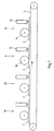
- FIG. 1 shows, in a schematic form, an apparatus for producing a structured surface on a workpiece, which in the present case is designed as a plate 2.
- a workpiece which in the present case is designed as a plate 2.
- a plurality of plates 2 are arranged on a conveyor belt 4, which are individually fed sequentially to different processing stations.
- the conveying direction is indicated in Fig. 1 with an arrow and extends from left to right.
- a large-area workpiece or an endlessly produced workpiece can be processed, which is divided into individual plates 2 after the processing described below.
- the processing stations 6 and 8 shown in FIG. 1 have in common that a coating is applied to them in each case.
- the two coatings consist of a same paint.
- the invention is not limited thereto, so it can also be applied by the processing stations coatings of different materials.
- paints and resins or synthetic resins can be applied.
- processing station 8 which applies a second coating to a first coating already connected to the workpiece 2, such as a laminate coating.
- a first substantially full-surface coating is applied from a lacquer.
- the processing station on an applicator roll 10, which applies a uniform layer of paint on the surface of the plates 2.
- the applied coating is at least partially dried and cured.
- the post-processing device 12 for example, by means of a hot air stream or by means of an electromagnetic radiation, in particular UV radiation cause the drying and curing.
- the post-processing device 12 corresponding means for generating the hot air flow or the radiation.
- a coating of a paint is applied directly by means of an applicator roll 14, wherein the order quantity varies spatially.
- the spatial structuring of the lacquer layer is produced in particular by a gravure roll, in the surface of which different sections having different levels are formed.
- the surface of a gravure roll is processed by means of pricking or engraving in order to produce individual recesses, so-called wells, usually in rhombic form, with different depths.
- a paint or varnish is applied which is received in the cavities to be partially dispensed from the cavities onto the surface of the medium during transfer to another medium.
- the last applied coating is then at least partially cured, so that the spatially different structuring is fixed before it balances due to bleeding again. In this curing step, it may also come to a possibly incomplete curing of the arranged underneath, applied in the first processing station 6 coating.
- the two paint layers consist of the same paint, as this facilitates the bonding of the two coatings.
- different composition of the two coatings can be chosen, for example, to emphasize and enhance the surface effects of structuring.
- the differences may be, for example, in the color of the two coatings or in the degree of gloss.
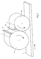
- Fig. 2 shows an applicator roll 14, which applies the paint on the surface of the plate 2 in a direct printing process.
- the arrow again indicates the direction of movement of the plate 2.
- the structured lateral surface 15 of the applicator roll 14 (the structuring can not be seen in detail) takes up the lacquer, wherein the amount of the lacquer L is set by a doctor 17.
- this method is also called direct printing method.
- Fig. 3 shows the same roller 14, which is not used in this embodiment as a direct application roller, but first transfers the adhering paint on a separate applicator roll 19, which preferably has an elastic, preferably rubberized roll surface. From the applicator roller 19, the paint transferred from the roller 14 is then applied to the surface of the plate 2. The remainder of the paint L is doctored in the further rotation of the applicator roll 19 with the aid of a further doctor blade 21, before again paint from the roller 14 is transmitted. This process is also called indirect printing process.
- FIG. 4 shows a further embodiment of the applicator roll arrangement.
- 17 separate paint strands are applied to an applicator roll 14 with a smooth surface by means of a profiled doctor blade. After application to the surface of the plate 2 then results in a line structure.
- the density of the lacquer strands, their distances and their diameter can be freely selected by setting the profiling.
- by a preferably oscillating movement of the doctor blade transversely to the direction of movement of the plate 2 it is possible to generate a wave-like arrangement of the lacquer strands on the plate surface.
- a further embodiment of the doctor blade arrangement is that instead of the one profiled doctor blade 17, two identically profiled doctor blades are provided. If both doctor blades are aligned, the lacquer strands are applied to the roll surface. If the two squeegees are shifted against each other, the order of the paint strands is interrupted. By a selective shifting against each other interrupted structures can be created.
- FIG. 5 shows a further embodiment of a device for producing a structured surface on a plate 2, in which instead of the applicator roller arrangement described above, a digital application device 30 for applying the second coating is provided.
- a jet printing technique is used, which is particularly widespread in so-called inkjet printers.
- Fig. 5 is below the applicator a short dash is drawn in, which indicates the row of droplet jets.
- the applicator device applies the paint line by line transversely to the direction of movement of the plate 2.
- a computer 31 as a means for generating a dot distribution for controlling the digital application device is connected to the application device 30.
- the computer 31 prepares digital control information and transmits it to the application device.
- the post-processing device 32 adjoins the digital application device in order to dry and at least partially cure the previously applied second coating.
- an optical scanning device 34 is advantageously provided to detect the surface pattern of the surface of the plate 2 or possibly the first coating.
- the optical pickup detects the surface and transmits the detected data to the computer 31.
- the computer 31 calculates a dot distribution to be generated from the readings of the optical pickup 34. This is then applied with the digital applicator 30 as a second coating.
- the optical scanning device can be designed as a scanner, as a line camera or as an area camera. aim In any case, it is the optical pickup that detects the surface at a resolution or evaluates the picked data at a resolution that the digital applicator should apply the patterned second coating.
- the digital application device 30 applies the structured second coating to the surface in such a way that the surface structure coincides with the optical pattern at least partially matches.
- a synchronous haptic and optical surface design of the plate 2 can be achieved in this way.
- Fig. 1 is further shown that the surface of the plates 2 are provided before applying the two coatings described above by means of the processing stations 6 and 8 by means of two further processing stations 18 and 20, each with a coating.
- This can be in particular lacquer layers with which a two-tone surface, a decor is produced.
- the processing stations 18 and 20, in a similar manner as previously described, have applicators and finishing devices without further description herein.
- the pre-painting represents a particularly preferred embodiment, because the surfaces produced therewith are completely painted and can thus be produced in a plant.
- the pre-painting in the two processing stations 18 and 20 can also by another arbitrary coating system can be replaced.
- a plant for laminate coating or veneer coating can be provided, which are then provided by the processing stations 6 and 8 with the coatings described above.
- a further preferred embodiment of the device is that the two processing stations 18 and 20 apply a varying pattern in the area, for example a wood decor.
- the two applicator rollers of the processing stations 18 and 20 are synchronized in order to apply matching and complementary color patterns.
- the gravure roller 14 is provided with a surface engraving whose image also coincides with the applied by the processing stations 18 and 20 printed images.
- the rotation of the gravure roller 14 is synchronized with the rotation of the applicator rollers of the processing stations 18 and 20 such that the spatially varying distribution of the second coating coincides with the printed image applied by the processing stations 18 and 20.
- a synchronized with the printed pattern varying distribution of the top coat layer such as a pore structure suitable for wood decor can be achieved.
- FIG. 6a and 6b show a first embodiment of a structured surface of a plate 2.
- a first coating 22 of a paint or of another material over the entire surface been applied.
- a second coating 24 has also been applied, which has a spatially varying distribution of the application amount.
- the variation in this case means a pore structure that is intended, for example, to imitate a wood decor.
- the pores are formed as elongated recesses 26, as is apparent in particular from the enlargement in Fig. 6b.
- the second coating 24 thus consists of the areas that are not formed as a recess.
- the pores 26 are shown in this schematic representation substantially rectangular in cross-section with slightly rounded edges. In practice, however, a distribution which differs more clearly from the rectangular shape may occur, since the regions of the second coating 24 in the edge regions of the recesses 26 partially dissolve before being cured. Rounded corners are therefore to be expected at real recesses 26.
- the spatial distribution of the application amount of the second coating shown in FIG. 6 a results in a pore structure in which the pores actually form depressions in the coating 24.
- a structure can also be called a positive surface structure.
- FIGS. 7 a to 7 c show a similar surface structure of a second coating 24, in which the pores are formed as elevations 28.
- a surface structure may therefore be referred to as a negative surface structure.
- the actually to be expected as a depression pores are formed as elevations.
- the size of the structures is so small that at normal View by a user the negative surface structure can not be distinguished from a positive surface structure.
- the second coating 24 thus consists of the areas that have been applied as elevations, that is, for example, as negative pores.
- the area coverage of the second coating is therefore considerably lower than in the embodiment according to FIGS. 6a and 6b.
- Fig. 7b shows in an enlargement the cross-sectional shape of the negative pore.
- the cross-sectional shape of the pore with rounded edges is shown here. This form is to be expected if the applied paint partially dissolves before curing to the forming edges.
- FIG. 7b shows a continuous course of the elevation or of the negative pore 28.
- FIG. 7c shows a substructure present within the applied negative pore 28. This substructure consists of individual spaced individual elevations 29, which arise due to the application techniques described above.
- this substructure may arise during application by means of an embossed or engraved roll shell surface, that is to say if the surface has individual wells which in each case emit the adhering lacquer. Because the wells are spaced, the dispensed droplets of paint are also spaced on the first coating 22, thus leading to the substructure.
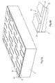
- FIG. 8 shows, by way of example, a geometric pattern of the spatially varying distribution of the application quantity of the second coating.
- the illustrated pattern is a diamond pattern that has recessed and raised diamonds. In this form of spatial distribution, it is not possible to distinguish between a negative or a positive structure that has the same number of raised and recessed areas.
- the method is based on the principle of the known light-section method with optical triangulation, whereby a relative movement of measuring cell and measuring object is assumed.
- the mode of operation consists of illuminating the surface area to be measured with a suitable light source (laser) and using a surface camera to capture the light stripe imaged on the object.
- the surface normals of the illumination and the camera are tilted at a triangulation angle to each other.
- the camera then sees the projection line as a contour line reproducing the contour of the test object, from whose coordinates and the associated positions a three-dimensional profile can be calculated.
- the resolution of the known techniques achieves an accuracy in the vertical direction of less than 0.1 ⁇ m.
- the structured surface of the second coating can be examined and analyzed.
Priority Applications (5)
| Application Number | Priority Date | Filing Date | Title |
|---|---|---|---|
| EP10158405.0A EP2218520B1 (fr) | 2004-10-05 | 2004-12-02 | Procédé et dispositif de fabrication d'une surface structurée |
| PL04028565T PL1645339T3 (pl) | 2004-10-05 | 2004-12-02 | Sposób wytwarzania strukturalnej powierzchni oraz płyty ze strukturalną powierzchnią |
| PL10158405T PL2218520T3 (pl) | 2004-10-05 | 2004-12-02 | Sposób i urządzenie do wytwarzania powierzchni strukturyzowanej |
| PCT/EP2005/010796 WO2006037644A2 (fr) | 2004-10-05 | 2005-10-05 | Procede et dispositif pour produire une surface structuree et piece a surface structuree |
| RU2007116965/11A RU2356639C2 (ru) | 2004-10-05 | 2005-10-05 | Способ и устройство для изготовления структурированной поверхности и заготовка со структурированной поверхностью |
Applications Claiming Priority (1)
| Application Number | Priority Date | Filing Date | Title |
|---|---|---|---|
| DE102004049022 | 2004-10-05 |
Related Child Applications (1)
| Application Number | Title | Priority Date | Filing Date |
|---|---|---|---|
| EP10158405.0A Division-Into EP2218520B1 (fr) | 2004-10-05 | 2004-12-02 | Procédé et dispositif de fabrication d'une surface structurée |
Publications (2)
| Publication Number | Publication Date |
|---|---|
| EP1645339A1 true EP1645339A1 (fr) | 2006-04-12 |
| EP1645339B1 EP1645339B1 (fr) | 2015-07-08 |
Family
ID=34306515
Family Applications (2)
| Application Number | Title | Priority Date | Filing Date |
|---|---|---|---|
| EP04028565.2A Active EP1645339B1 (fr) | 2004-10-05 | 2004-12-02 | Procédé et appareil pour faire une surface structurée et objet manufacturé avec une surface structurée |
| EP10158405.0A Active EP2218520B1 (fr) | 2004-10-05 | 2004-12-02 | Procédé et dispositif de fabrication d'une surface structurée |
Family Applications After (1)
| Application Number | Title | Priority Date | Filing Date |
|---|---|---|---|
| EP10158405.0A Active EP2218520B1 (fr) | 2004-10-05 | 2004-12-02 | Procédé et dispositif de fabrication d'une surface structurée |
Country Status (6)
| Country | Link |
|---|---|
| EP (2) | EP1645339B1 (fr) |
| DE (1) | DE202004018710U1 (fr) |
| ES (2) | ES2545665T3 (fr) |
| PL (2) | PL1645339T3 (fr) |
| RU (1) | RU2356639C2 (fr) |
| WO (1) | WO2006037644A2 (fr) |
Cited By (21)
| Publication number | Priority date | Publication date | Assignee | Title |
|---|---|---|---|---|
| WO2008061791A1 (fr) * | 2006-11-23 | 2008-05-29 | Kronoplus Technical Ag | Plaque revêtue en matériau à base de bois |
| EP2050514A2 (fr) | 2007-10-19 | 2009-04-22 | Robert Bürkle GmbH | Procédé et dispositif de fabrication d'une surface structurée d'une plaque de matière laquée |
| WO2010037733A1 (fr) | 2008-10-02 | 2010-04-08 | Fritz Egger Gmbh & Co. Og | Panneau, en particulier panneau de plancher |
| DE102008051211A1 (de) * | 2008-10-14 | 2010-04-22 | Guido Schulte | Boden-, Wand- oder Deckenpaneel und Verfahren zur Herstellung eines solchen Paneels |
| DE102008052883A1 (de) | 2008-10-23 | 2010-04-29 | Fritz Egger Gmbh & Co. | Bauelement aus Holzwerkstoff mit besonderen haptischen Eigenschaften und Verfahren zur Herstellung eines solchen Bauelements |
| EP2181860A2 (fr) | 2008-10-22 | 2010-05-05 | Fritz Egger GmbH & Co. OG | Composant en matière dérivée du bois doté de propriétés tactiles particulières et procédé de fabrication d'un tel composant |
| DE102009004482A1 (de) | 2009-01-09 | 2010-07-15 | Fritz Egger Gmbh & Co. | Bauelement aus Holzwerkstoff mit aufgedrucktem Dekor und unterschiedlichem Glanzgrad |
| EP2251205A2 (fr) | 2009-05-14 | 2010-11-17 | Jesús Francisco Barberan Latorre | Système pour appliquer des vernis avec un relief |
| EP2301762A1 (fr) * | 2010-03-11 | 2011-03-30 | Flooring Technologies Ltd. | Procédé et un dispositif d'application d'une structure sur une plaque en matériau dérivé du bois |
| US20130177716A1 (en) * | 2012-01-11 | 2013-07-11 | D. Edward Wheatley | Method of manufacturing a substrate having a textured surface |
| US8865267B2 (en) | 2005-11-24 | 2014-10-21 | Kronoplus Technical Ag | Coated board of wood-based material and a method of producing same |
| EP2857221A1 (fr) | 2013-10-07 | 2015-04-08 | Flooring Technologies Ltd. | Panneau doté d'une surface ultra-mate |
| EP2873535A1 (fr) | 2013-11-15 | 2015-05-20 | Flooring Technologies Ltd. | Pièces dotées d'une surface de décor structuré |
| WO2016174021A1 (fr) | 2015-04-30 | 2016-11-03 | Klebchemie M. G. Becker Gmbh & Co. Kg | Procédé de réalisation de surfaces structurées et objets ainsi structurés |
| EP3090882A1 (fr) | 2015-05-08 | 2016-11-09 | Robert Bürkle GmbH | Piece en forme de plaque comprenant une surface ayant des differentes de brillance, procede de production d'une telle surface et installation destinee a executer le procede |
| FR3042426A1 (fr) * | 2015-10-19 | 2017-04-21 | Peugeot Citroen Automobiles Sa | Procede de peinture a deux teintes d’elements de carrosserie de vehicule automobile |
| CN106985563A (zh) * | 2010-11-10 | 2017-07-28 | 地材科技有限公司 | 将饰纹施加至复合木板的方法 |
| WO2017198550A1 (fr) | 2016-05-20 | 2017-11-23 | Fritz Egger Gmbh & Co. Og | Procédé de fabrication d'un profilé de chant et partie de meuble |
| DE102010025159B4 (de) * | 2010-06-25 | 2018-11-15 | Hamberger Industriewerke Gmbh | Verfahren zum farblichen Gestalten von strukturierten Holzoberflächen sowie ein Fußboden- oder Verkleidungspaneel mit einer Holzoberfläche |
| CN109433516A (zh) * | 2018-10-23 | 2019-03-08 | 刘景岳 | 一种建筑模板用涂胶装置 |
| EP3611108A1 (fr) * | 2016-11-02 | 2020-02-19 | Coveris Rigid (Zell) Deutschland GmbH | Emballage en forme de coupe ou de coquille |
Families Citing this family (32)
| Publication number | Priority date | Publication date | Assignee | Title |
|---|---|---|---|---|
| EP2269744B1 (fr) † | 2004-05-28 | 2019-12-18 | SWISS KRONO Tec AG | Panneau en matière dérivée du bois doté d'un revêtement de surface |
| WO2007036349A1 (fr) * | 2005-09-27 | 2007-04-05 | Nikolaus Vida | Procede de profilage d'une surface |
| CN105499062B (zh) * | 2005-11-24 | 2017-08-15 | 克诺普拉斯技术股份公司 | 用流动性涂层材料为光滑的或具有构造结构的表面涂层的涂层设备 |
| DE102006004144B4 (de) * | 2006-01-27 | 2022-12-29 | Hymmen GmbH Maschinen- und Anlagenbau | Vorrichtung und Verfahren zum Beschichten von Platten |
| DE102006005089B4 (de) * | 2006-02-04 | 2015-04-16 | Preh Gmbh | Bedienelement |
| DE102006058612A1 (de) * | 2006-12-11 | 2008-06-19 | Fritz Egger Gmbh & Co. | Optimierte Trägerplatte |
| DE102007019871A1 (de) | 2007-04-25 | 2008-10-09 | Theodor Hymmen Holding Gmbh | Verfahren und Vorrichtung zur Erzeugung einer dünnen dreidimensional strukturierten Oberfläche auf plattenförmigen Werkstoffen |
| DE102007028822A1 (de) | 2007-06-20 | 2008-12-24 | Theodor Hymmen Holding Gmbh | Verfahren und Vorrichtung zur dekorativen Beschichtung einer Platte |
| DE102007039949B3 (de) | 2007-08-23 | 2008-12-04 | Flooring Technologies Ltd. | Vorrichtung zum Auftragen einer Suspension auf eine Trägerplatte |
| DE102007062941B4 (de) | 2007-12-21 | 2012-10-18 | Surface Technologies Gmbh & Co. Kg | Verfahren zur Herstellung eines Laminats |
| WO2009121857A1 (fr) * | 2008-04-04 | 2009-10-08 | Akzo Nobel Coatings International B.V. | Procédé d'application de tache |
| DE102008050605A1 (de) * | 2008-10-09 | 2010-04-15 | Merck Patent Gmbh | Beschichtungsverfahren |
| DE102009009646A1 (de) * | 2009-02-19 | 2010-09-30 | SÜDDEKOR GmbH | Dekorprodukt, Verfahren zum Herstellen eines Dekorprodukts und Verwendung eines Dekorprodukts zum Herstellen einer dekorierten Trägerfläche |
| PL2251501T3 (pl) | 2009-05-14 | 2014-02-28 | Flooring Technologies Ltd | Sposób nanoszenia struktury na powierzchnię wykładziny |
| DK2363299T3 (da) | 2010-03-05 | 2013-01-28 | Spanolux N V Div Balterio | Fremgangsmåde til fremstilling af en gulvplade |
| DE102010036454B4 (de) * | 2010-07-16 | 2012-09-27 | Fritz Egger Gmbh & Co. Og | Verfahren zum Herstellen eines ein Dekor und eine dreidimensionale Struktur aufweisenden Paneels und Paneel, hergestellt nach dem Verfahren |
| JP5756317B2 (ja) * | 2011-03-31 | 2015-07-29 | ニチハ株式会社 | 建築板及びその製造方法 |
| UA111997C2 (uk) * | 2012-04-02 | 2016-07-11 | Кроноплюс Текнікал Аг | Панель з покриттям, нанесеним методом прямого друку |
| DE102012103491A1 (de) * | 2012-04-20 | 2013-10-24 | Fritz Egger Gmbh & Co. Og | Verfahren und Vorrichtung zur Herstellung einer strukturierten Lackoberfläche |
| DE102013109850A1 (de) | 2013-06-28 | 2014-12-31 | J.H. Tönnjes GmbH & Co. KG | Verfahren zum Herstellen eines Kennzeichens und Kennzeichen |
| CH708805B1 (de) * | 2013-11-01 | 2017-11-15 | Proverum Ag | Verfahren und Vorrichtung zum Erzeugen einer vorgegebenen Oberflächenstruktur in einer flächigen Materialportion. |
| DE102014109548A1 (de) * | 2014-07-08 | 2016-01-14 | Thyssenkrupp Ag | Bandbeschichtungsverfahren zur Herstellung eines Halbzeugs mit einer Oberflächenstruktur |
| DE102015219102A1 (de) * | 2015-10-02 | 2017-04-06 | Homag Gmbh | Verfahren zum Beschichten eines bevorzugt plattenförmigen Werkstücks |
| PL3415316T3 (pl) | 2017-06-13 | 2020-10-05 | Hymmen GmbH Maschinen- und Anlagenbau | Sposób i urządzenie do wytwarzania strukturyzowanej powierzchni |
| EP3415317B2 (fr) * | 2017-06-13 | 2023-09-06 | Hymmen GmbH Maschinen- und Anlagenbau | Procédé et dispositif de fabrication d'une surface décorative |
| RU185116U1 (ru) * | 2018-04-16 | 2018-11-22 | Михаил Владимирович Бадамов | Художественное покрытие пола |
| US11203224B2 (en) | 2018-08-30 | 2021-12-21 | Interface, Inc. | Digital printing for flooring and decorative structures |
| DE102019206431A1 (de) | 2019-05-03 | 2020-11-05 | Hymmen GmbH Maschinen- und Anlagenbau | Verfahren zum Herstellen einer Struktur auf einer Oberfläche |
| ES2960896T3 (es) * | 2019-12-12 | 2024-03-07 | Akzenta Paneele Profile Gmbh | Película de protección contra el desgaste estructurada mediante impresión digital con nivel de brillo ajustable |
| CN111054570B (zh) * | 2019-12-23 | 2021-06-15 | 钟思端 | 一种木板自动上胶机 |
| CN111729807B (zh) * | 2020-07-01 | 2021-06-15 | 美述家智能家居有限公司 | 一种用于复合木板油漆涂装的自动加工设备 |
| DE102021103564A1 (de) * | 2021-02-16 | 2022-08-18 | Homag Gmbh | Verfahren sowie eine Vorrichtung zum Beschichten einer Oberfläche |
Family Cites Families (10)
| Publication number | Priority date | Publication date | Assignee | Title |
|---|---|---|---|---|
| GB1242341A (en) | 1969-02-06 | 1971-08-11 | Electrolux Ltd | Grain printing process |
| SE7403924L (fr) | 1973-10-04 | 1975-04-07 | Reliance Universal | |
| DE2919847B1 (de) | 1979-05-16 | 1980-10-16 | Lissmann Alkor Werk | Flaechengebilde mit Holzmaserung und Verfahren zu dessen Herstellung |
| US5178928A (en) * | 1988-09-22 | 1993-01-12 | Dai Nippon Insatsu Kabushiki Kaisha | Decorative materials |
| DE4421559C2 (de) | 1994-06-20 | 1998-05-20 | Osmetric Entwicklungs Und Prod | Verfahren zum Herstellen einer Beschichtung, die eine Struktur aufweist, auf einem Substrat sowie Beschichtung |
| DE19502389A1 (de) | 1995-01-26 | 1996-08-01 | Bausch Ag | Verfahren zum Erzeugen von strukturierten Schichten auf flächigen Trägermaterialien |
| DE19532819A1 (de) | 1995-09-06 | 1997-03-13 | Hofa Homann Verwaltungsgesells | Verfahren zur Herstellung einer Holzwerkstoffplatte |
| DE19741680C1 (de) | 1997-09-22 | 1998-12-03 | Wkp Wuerttembergische Kunststo | Bahnförmige Matrize zum Erzeugen von Oberflächenmaterialien sowie Verfahren zum Herstellen einer solchen Matrize |
| JP4046253B2 (ja) | 1998-05-20 | 2008-02-13 | 大日本印刷株式会社 | 同調エンボス化粧シート及びその製造方法 |
| SE516696C2 (sv) | 1999-12-23 | 2002-02-12 | Perstorp Flooring Ab | Förfarande för framställning av ytelement vilka innefattar ett övre dekorativt skikt samt ytelement framställda enlit förfarandet |
-
2004
- 2004-12-02 EP EP04028565.2A patent/EP1645339B1/fr active Active
- 2004-12-02 EP EP10158405.0A patent/EP2218520B1/fr active Active
- 2004-12-02 ES ES04028565.2T patent/ES2545665T3/es active Active
- 2004-12-02 PL PL04028565T patent/PL1645339T3/pl unknown
- 2004-12-02 DE DE202004018710U patent/DE202004018710U1/de not_active Expired - Lifetime
- 2004-12-02 PL PL10158405T patent/PL2218520T3/pl unknown
- 2004-12-02 ES ES10158405T patent/ES2425197T3/es active Active
-
2005
- 2005-10-05 WO PCT/EP2005/010796 patent/WO2006037644A2/fr active Application Filing
- 2005-10-05 RU RU2007116965/11A patent/RU2356639C2/ru active
Non-Patent Citations (1)
| Title |
|---|
| No Search * |
Cited By (33)
| Publication number | Priority date | Publication date | Assignee | Title |
|---|---|---|---|---|
| US10406558B2 (en) | 2005-11-24 | 2019-09-10 | Xylo Technologies Ag | Coated board of wood-based material |
| US8865267B2 (en) | 2005-11-24 | 2014-10-21 | Kronoplus Technical Ag | Coated board of wood-based material and a method of producing same |
| EP2314381A1 (fr) * | 2006-11-23 | 2011-04-27 | Kronoplus Technical AG | Procédé de revêtement de plaque de matériau en bois |
| WO2008061791A1 (fr) * | 2006-11-23 | 2008-05-29 | Kronoplus Technical Ag | Plaque revêtue en matériau à base de bois |
| EP2050514A2 (fr) | 2007-10-19 | 2009-04-22 | Robert Bürkle GmbH | Procédé et dispositif de fabrication d'une surface structurée d'une plaque de matière laquée |
| EP2050514A3 (fr) * | 2007-10-19 | 2009-12-23 | Robert Bürkle GmbH | Procédé et dispositif de fabrication d'une surface structurée d'une plaque de matière laquée |
| WO2010037733A1 (fr) | 2008-10-02 | 2010-04-08 | Fritz Egger Gmbh & Co. Og | Panneau, en particulier panneau de plancher |
| DE102008049941B3 (de) * | 2008-10-02 | 2010-04-29 | Fritz Egger Gmbh & Co. | Paneel, insbesondere Fußbodenpaneel |
| DE102008051211A1 (de) * | 2008-10-14 | 2010-04-22 | Guido Schulte | Boden-, Wand- oder Deckenpaneel und Verfahren zur Herstellung eines solchen Paneels |
| EP2181860A3 (fr) * | 2008-10-22 | 2012-03-14 | Fritz Egger GmbH & Co. OG | Composant en matière dérivée du bois doté de propriétés tactiles particulières et procédé de fabrication d'un tel composant |
| EP2181860A2 (fr) | 2008-10-22 | 2010-05-05 | Fritz Egger GmbH & Co. OG | Composant en matière dérivée du bois doté de propriétés tactiles particulières et procédé de fabrication d'un tel composant |
| DE102008052883B4 (de) * | 2008-10-23 | 2012-02-23 | Fritz Egger Gmbh & Co. | Bauelement aus Holzwerkstoff mit besonderen haptischen Eigenschaften und Verfahren zur Herstellung eines solchen Bauelements |
| DE102008052883A1 (de) | 2008-10-23 | 2010-04-29 | Fritz Egger Gmbh & Co. | Bauelement aus Holzwerkstoff mit besonderen haptischen Eigenschaften und Verfahren zur Herstellung eines solchen Bauelements |
| WO2010079014A3 (fr) * | 2009-01-09 | 2010-10-21 | Fritz Egger Gmbh & Co. Og | Élément de construction en matériau dérivé du bois à décor imprimé et degré de brillance variable |
| WO2010079014A2 (fr) * | 2009-01-09 | 2010-07-15 | Fritz Egger Gmbh & Co. Og | Élément de construction en matériau dérivé du bois à décor imprimé et degré de brillance variable |
| DE102009004482A1 (de) | 2009-01-09 | 2010-07-15 | Fritz Egger Gmbh & Co. | Bauelement aus Holzwerkstoff mit aufgedrucktem Dekor und unterschiedlichem Glanzgrad |
| EP2251205A2 (fr) | 2009-05-14 | 2010-11-17 | Jesús Francisco Barberan Latorre | Système pour appliquer des vernis avec un relief |
| EP2301762A1 (fr) * | 2010-03-11 | 2011-03-30 | Flooring Technologies Ltd. | Procédé et un dispositif d'application d'une structure sur une plaque en matériau dérivé du bois |
| DE102010025159B4 (de) * | 2010-06-25 | 2018-11-15 | Hamberger Industriewerke Gmbh | Verfahren zum farblichen Gestalten von strukturierten Holzoberflächen sowie ein Fußboden- oder Verkleidungspaneel mit einer Holzoberfläche |
| CN106985563A (zh) * | 2010-11-10 | 2017-07-28 | 地材科技有限公司 | 将饰纹施加至复合木板的方法 |
| US20130177716A1 (en) * | 2012-01-11 | 2013-07-11 | D. Edward Wheatley | Method of manufacturing a substrate having a textured surface |
| EP2857221A1 (fr) | 2013-10-07 | 2015-04-08 | Flooring Technologies Ltd. | Panneau doté d'une surface ultra-mate |
| EP2873535A1 (fr) | 2013-11-15 | 2015-05-20 | Flooring Technologies Ltd. | Pièces dotées d'une surface de décor structuré |
| DE102015005495A1 (de) | 2015-04-30 | 2016-11-03 | Klebchemie M.G. Becker Gmbh & Co. Kg | Verfahren zur Herstellung von strukturierten Oberflächen und derart strukturierte Gegenstände |
| WO2016174021A1 (fr) | 2015-04-30 | 2016-11-03 | Klebchemie M. G. Becker Gmbh & Co. Kg | Procédé de réalisation de surfaces structurées et objets ainsi structurés |
| EP3090882A1 (fr) | 2015-05-08 | 2016-11-09 | Robert Bürkle GmbH | Piece en forme de plaque comprenant une surface ayant des differentes de brillance, procede de production d'une telle surface et installation destinee a executer le procede |
| DE102015107259A1 (de) | 2015-05-08 | 2016-11-10 | Robert Bürkle GmbH | Plattenförmiges Werkstück mit einer Oberfläche mit Glanzgradunterschieden, Verfahren zum Erzeugen einer solchen Oberfläche und Anlage zur Durchführung des Verfahrens |
| FR3042426A1 (fr) * | 2015-10-19 | 2017-04-21 | Peugeot Citroen Automobiles Sa | Procede de peinture a deux teintes d’elements de carrosserie de vehicule automobile |
| WO2017198550A1 (fr) | 2016-05-20 | 2017-11-23 | Fritz Egger Gmbh & Co. Og | Procédé de fabrication d'un profilé de chant et partie de meuble |
| DE102016109361A1 (de) | 2016-05-20 | 2017-11-23 | Fritz Egger Gmbh & Co. Og | Verfahren zum Herstellen eines Kantenprofils und Möbelteil |
| RU2716191C1 (ru) * | 2016-05-20 | 2020-03-06 | Фриц Эггер Гмбх Унд Ко. Ог | Способ изготовления профиля кромки и элемента мебели |
| EP3611108A1 (fr) * | 2016-11-02 | 2020-02-19 | Coveris Rigid (Zell) Deutschland GmbH | Emballage en forme de coupe ou de coquille |
| CN109433516A (zh) * | 2018-10-23 | 2019-03-08 | 刘景岳 | 一种建筑模板用涂胶装置 |
Also Published As
| Publication number | Publication date |
|---|---|
| DE202004018710U1 (de) | 2005-03-10 |
| RU2356639C2 (ru) | 2009-05-27 |
| EP1645339B1 (fr) | 2015-07-08 |
| ES2425197T3 (es) | 2013-10-14 |
| EP2218520A2 (fr) | 2010-08-18 |
| EP2218520A3 (fr) | 2011-03-02 |
| PL1645339T3 (pl) | 2015-12-31 |
| ES2545665T3 (es) | 2015-09-14 |
| PL2218520T3 (pl) | 2013-11-29 |
| RU2007116965A (ru) | 2008-11-20 |
| EP2218520B1 (fr) | 2013-06-12 |
| WO2006037644A2 (fr) | 2006-04-13 |
Similar Documents
| Publication | Publication Date | Title |
|---|---|---|
| EP1645339B1 (fr) | Procédé et appareil pour faire une surface structurée et objet manufacturé avec une surface structurée | |
| EP3415319B1 (fr) | Procédé et dispositif de fabrication d'une surface décorative | |
| EP1761400B1 (fr) | Panneau dote d'une surface decorative | |
| DE102009044802B4 (de) | Verfahren und Vorrichtung zur Erzeugung einer dreidimensionalen Oberflächenstruktur auf einem Werkstück | |
| EP2593244B1 (fr) | Procédé de fabrication d'un panneau doté d'un décor et d'une structure à trois dimensions | |
| EP1980418B1 (fr) | Procédé de finissage d'une plaque en matériau à base de bois | |
| EP2873535A1 (fr) | Pièces dotées d'une surface de décor structuré | |
| EP3415318A1 (fr) | Procédé et dispositif de fabrication d'une pièce à usiner décorative et pièce à usiner | |
| EP3415317B2 (fr) | Procédé et dispositif de fabrication d'une surface décorative | |
| EP2301762B9 (fr) | Procédé et un dispositif d'application d'une structure sur une plaque en matériau dérivé du bois | |
| EP2181860B1 (fr) | Composant en matière dérivée du bois doté de propriétés tactiles particulières et procédé de fabrication d'un tel composant | |
| DE102008008240B4 (de) | Verfahren zur Herstellung einer Bauplatte, Vorrichtung zur Durchführung des Verfahrens und Fußbodenpaneel | |
| EP2838671B1 (fr) | Procédé et dispositif destinés à produire une surface peinte structurée | |
| DE102017113035B4 (de) | Verfahren und Vorrichtung zur Herstellung einer dekorativen Oberfläche | |
| DE102017113036B4 (de) | Verfahren und Vorrichtung zur Herstellung eines dekorativen Werkstückes und Werkstück | |
| EP3892388A1 (fr) | Procédé et dispositif de fabrication d'une surface structurée d'une matière en forme de plaque | |
| EP3999358B1 (fr) | Procédé de fabrication d'une structure sur une surface | |
| EP4134242B1 (fr) | Procédé et dispositif d'application d'un décor et d'une structure de surface sur une matière porteuse | |
| DE102008052883B4 (de) | Bauelement aus Holzwerkstoff mit besonderen haptischen Eigenschaften und Verfahren zur Herstellung eines solchen Bauelements | |
| EP2179864B1 (fr) | Procédé d'affinement d'une plaque de support |
Legal Events
| Date | Code | Title | Description |
|---|---|---|---|
| PUAI | Public reference made under article 153(3) epc to a published international application that has entered the european phase |
Free format text: ORIGINAL CODE: 0009012 |
|
| 17P | Request for examination filed |
Effective date: 20050928 |
|
| AK | Designated contracting states |
Kind code of ref document: A1 Designated state(s): AT BE BG CH CY CZ DE DK EE ES FI FR GB GR HU IE IS IT LI LT LU MC NL PL PT RO SE SI SK TR |
|
| AX | Request for extension of the european patent |
Extension state: AL BA HR LV MK YU |
|
| AKX | Designation fees paid |
Designated state(s): AT BE BG CH CY CZ DE DK EE ES FI FR GB GR HU IE IS IT LI LT LU MC NL PL PT RO SE SI SK TR |
|
| AXX | Extension fees paid |
Extension state: BA Payment date: 20050928 Extension state: HR Payment date: 20050928 Extension state: AL Payment date: 20050928 |
|
| 17Q | First examination report despatched |
Effective date: 20060131 |
|
| APBK | Appeal reference recorded |
Free format text: ORIGINAL CODE: EPIDOSNREFNE |
|
| APBN | Date of receipt of notice of appeal recorded |
Free format text: ORIGINAL CODE: EPIDOSNNOA2E |
|
| APBR | Date of receipt of statement of grounds of appeal recorded |
Free format text: ORIGINAL CODE: EPIDOSNNOA3E |
|
| APAV | Appeal reference deleted |
Free format text: ORIGINAL CODE: EPIDOSDREFNE |
|
| RAP1 | Party data changed (applicant data changed or rights of an application transferred) |
Owner name: FRITZ EGGER GMBH & CO. OG Owner name: THEODOR-HYMMEN HOLDING GMBH |
|
| APBT | Appeal procedure closed |
Free format text: ORIGINAL CODE: EPIDOSNNOA9E |
|
| RAP1 | Party data changed (applicant data changed or rights of an application transferred) |
Owner name: THEODOR HYMMEN VERWALTUNGS GMBH Owner name: FRITZ EGGER GMBH & CO. OG |
|
| GRAP | Despatch of communication of intention to grant a patent |
Free format text: ORIGINAL CODE: EPIDOSNIGR1 |
|
| INTG | Intention to grant announced |
Effective date: 20141124 |
|
| GRAS | Grant fee paid |
Free format text: ORIGINAL CODE: EPIDOSNIGR3 |
|
| GRAP | Despatch of communication of intention to grant a patent |
Free format text: ORIGINAL CODE: EPIDOSNIGR1 |
|
| RAP1 | Party data changed (applicant data changed or rights of an application transferred) |
Owner name: FRITZ EGGER GMBH & CO. OG Owner name: THEODOR HYMMEN VERWALTUNGS GMBH |
|
| INTG | Intention to grant announced |
Effective date: 20150507 |
|
| GRAA | (expected) grant |
Free format text: ORIGINAL CODE: 0009210 |
|
| STAA | Information on the status of an ep patent application or granted ep patent |
Free format text: STATUS: THE PATENT HAS BEEN GRANTED |
|
| RAP1 | Party data changed (applicant data changed or rights of an application transferred) |
Owner name: THEODOR HYMMEN VERWALTUNGS GMBH Owner name: FRITZ EGGER GMBH & CO. OG |
|
| AK | Designated contracting states |
Kind code of ref document: B1 Designated state(s): AT BE BG CH CY CZ DE DK EE ES FI FR GB GR HU IE IS IT LI LT LU MC NL PL PT RO SE SI SK TR |
|
| AX | Request for extension of the european patent |
Extension state: AL BA HR |
|
| REG | Reference to a national code |
Ref country code: GB Ref legal event code: FG4D Free format text: NOT ENGLISH |
|
| REG | Reference to a national code |
Ref country code: DE Ref legal event code: R081 Ref document number: 502004014953 Country of ref document: DE Owner name: FRITZ EGGER GMBH & CO. OG, ST. JOHANN, AT Free format text: FORMER OWNERS: FRITZ EGGER GMBH & CO., UNTERRADLBERG, AT; THEODOR HYMMEN HOLDING GMBH, 33613 BIELEFELD, DE Ref country code: DE Ref legal event code: R081 Ref document number: 502004014953 Country of ref document: DE Owner name: HYMMEN GMBH MASCHINEN- UND ANLAGENBAU, DE Free format text: FORMER OWNERS: FRITZ EGGER GMBH & CO., UNTERRADLBERG, AT; THEODOR HYMMEN HOLDING GMBH, 33613 BIELEFELD, DE |
|
| REG | Reference to a national code |
Ref country code: AT Ref legal event code: REF Ref document number: 734955 Country of ref document: AT Kind code of ref document: T Effective date: 20150715 Ref country code: CH Ref legal event code: EP |
|
| REG | Reference to a national code |
Ref country code: IE Ref legal event code: FG4D Free format text: LANGUAGE OF EP DOCUMENT: GERMAN |
|
| REG | Reference to a national code |
Ref country code: CH Ref legal event code: NV Representative=s name: TROESCH SCHEIDEGGER WERNER AG, CH |
|
| REG | Reference to a national code |
Ref country code: DE Ref legal event code: R096 Ref document number: 502004014953 Country of ref document: DE |
|
| REG | Reference to a national code |
Ref country code: RO Ref legal event code: EPE |
|
| REG | Reference to a national code |
Ref country code: ES Ref legal event code: FG2A Ref document number: 2545665 Country of ref document: ES Kind code of ref document: T3 Effective date: 20150914 |
|
| REG | Reference to a national code |
Ref country code: SE Ref legal event code: TRGR |
|
| REG | Reference to a national code |
Ref country code: NL Ref legal event code: FP |
|
| REG | Reference to a national code |
Ref country code: FR Ref legal event code: PLFP Year of fee payment: 12 |
|
| REG | Reference to a national code |
Ref country code: LT Ref legal event code: MG4D |
|
| REG | Reference to a national code |
Ref country code: PL Ref legal event code: T3 |
|
| PG25 | Lapsed in a contracting state [announced via postgrant information from national office to epo] |
Ref country code: LT Free format text: LAPSE BECAUSE OF FAILURE TO SUBMIT A TRANSLATION OF THE DESCRIPTION OR TO PAY THE FEE WITHIN THE PRESCRIBED TIME-LIMIT Effective date: 20150708 Ref country code: GR Free format text: LAPSE BECAUSE OF FAILURE TO SUBMIT A TRANSLATION OF THE DESCRIPTION OR TO PAY THE FEE WITHIN THE PRESCRIBED TIME-LIMIT Effective date: 20151009 Ref country code: FI Free format text: LAPSE BECAUSE OF FAILURE TO SUBMIT A TRANSLATION OF THE DESCRIPTION OR TO PAY THE FEE WITHIN THE PRESCRIBED TIME-LIMIT Effective date: 20150708 |
|
| PG25 | Lapsed in a contracting state [announced via postgrant information from national office to epo] |
Ref country code: IS Free format text: LAPSE BECAUSE OF FAILURE TO SUBMIT A TRANSLATION OF THE DESCRIPTION OR TO PAY THE FEE WITHIN THE PRESCRIBED TIME-LIMIT Effective date: 20151108 Ref country code: PT Free format text: LAPSE BECAUSE OF FAILURE TO SUBMIT A TRANSLATION OF THE DESCRIPTION OR TO PAY THE FEE WITHIN THE PRESCRIBED TIME-LIMIT Effective date: 20151109 |
|
| REG | Reference to a national code |
Ref country code: DE Ref legal event code: R026 Ref document number: 502004014953 Country of ref document: DE |
|
| PLBI | Opposition filed |
Free format text: ORIGINAL CODE: 0009260 |
|
| PLBI | Opposition filed |
Free format text: ORIGINAL CODE: 0009260 |
|
| PG25 | Lapsed in a contracting state [announced via postgrant information from national office to epo] |
Ref country code: DK Free format text: LAPSE BECAUSE OF FAILURE TO SUBMIT A TRANSLATION OF THE DESCRIPTION OR TO PAY THE FEE WITHIN THE PRESCRIBED TIME-LIMIT Effective date: 20150708 Ref country code: EE Free format text: LAPSE BECAUSE OF FAILURE TO SUBMIT A TRANSLATION OF THE DESCRIPTION OR TO PAY THE FEE WITHIN THE PRESCRIBED TIME-LIMIT Effective date: 20150708 |
|
| 26 | Opposition filed |
Opponent name: ROBERT BUERKLE GMBH Effective date: 20160404 |
|
| 26 | Opposition filed |
Opponent name: FLOORING TECHNOLOGIES LTD. Effective date: 20160408 |
|
| PLAX | Notice of opposition and request to file observation + time limit sent |
Free format text: ORIGINAL CODE: EPIDOSNOBS2 |
|
| REG | Reference to a national code |
Ref country code: SK Ref legal event code: T3 Ref document number: E 20139 Country of ref document: SK |
|
| PG25 | Lapsed in a contracting state [announced via postgrant information from national office to epo] |
Ref country code: LU Free format text: LAPSE BECAUSE OF FAILURE TO SUBMIT A TRANSLATION OF THE DESCRIPTION OR TO PAY THE FEE WITHIN THE PRESCRIBED TIME-LIMIT Effective date: 20151202 Ref country code: MC Free format text: LAPSE BECAUSE OF FAILURE TO SUBMIT A TRANSLATION OF THE DESCRIPTION OR TO PAY THE FEE WITHIN THE PRESCRIBED TIME-LIMIT Effective date: 20150708 |
|
| PG25 | Lapsed in a contracting state [announced via postgrant information from national office to epo] |
Ref country code: SI Free format text: LAPSE BECAUSE OF FAILURE TO SUBMIT A TRANSLATION OF THE DESCRIPTION OR TO PAY THE FEE WITHIN THE PRESCRIBED TIME-LIMIT Effective date: 20150708 |
|
| REG | Reference to a national code |
Ref country code: IE Ref legal event code: MM4A |
|
| REG | Reference to a national code |
Ref country code: DE Ref legal event code: R082 Ref document number: 502004014953 Country of ref document: DE Representative=s name: PATENT- UND RECHTSANWAELTE LOESENBECK, SPECHT,, DE Ref country code: DE Ref legal event code: R081 Ref document number: 502004014953 Country of ref document: DE Owner name: HYMMEN GMBH MASCHINEN- UND ANLAGENBAU, DE Free format text: FORMER OWNERS: FRITZ EGGER GMBH & CO. OG, ST. JOHANN, TIROL, AT; THEODOR HYMMEN VERWALTUNGS GMBH, 33613 BIELEFELD, DE Ref country code: DE Ref legal event code: R081 Ref document number: 502004014953 Country of ref document: DE Owner name: FRITZ EGGER GMBH & CO. OG, ST. JOHANN, AT Free format text: FORMER OWNERS: FRITZ EGGER GMBH & CO. OG, ST. JOHANN, TIROL, AT; THEODOR HYMMEN VERWALTUNGS GMBH, 33613 BIELEFELD, DE |
|
| PLAF | Information modified related to communication of a notice of opposition and request to file observations + time limit |
Free format text: ORIGINAL CODE: EPIDOSCOBS2 |
|
| RAP2 | Party data changed (patent owner data changed or rights of a patent transferred) |
Owner name: FRITZ EGGER GMBH & CO. OG Owner name: HYMMEN GMBH MASCHINEN- UND ANLAGENBAU |
|
| PG25 | Lapsed in a contracting state [announced via postgrant information from national office to epo] |
Ref country code: IE Free format text: LAPSE BECAUSE OF NON-PAYMENT OF DUE FEES Effective date: 20151202 |
|
| PLBB | Reply of patent proprietor to notice(s) of opposition received |
Free format text: ORIGINAL CODE: EPIDOSNOBS3 |
|
| REG | Reference to a national code |
Ref country code: NL Ref legal event code: PD Owner name: HYMMEN GMBH MASCHINEN- UND ANLAGENBAU; DE Free format text: DETAILS ASSIGNMENT: CHANGE OF OWNER(S), ASSIGNMENT; FORMER OWNER NAME: THEODOR HYMMEN VERWALTUNGS GMBH Effective date: 20161129 Ref country code: FR Ref legal event code: PLFP Year of fee payment: 13 |
|
| REG | Reference to a national code |
Ref country code: AT Ref legal event code: PC Ref document number: 734955 Country of ref document: AT Kind code of ref document: T Owner name: FRITZ EGGER GMBH & CO. OG, AT Effective date: 20170223 Ref country code: AT Ref legal event code: PC Ref document number: 734955 Country of ref document: AT Kind code of ref document: T Owner name: HYMMEN GMBH MASCHINEN- UND ANLAGENBAU, DE Effective date: 20170223 |
|
| PG25 | Lapsed in a contracting state [announced via postgrant information from national office to epo] |
Ref country code: BG Free format text: LAPSE BECAUSE OF FAILURE TO SUBMIT A TRANSLATION OF THE DESCRIPTION OR TO PAY THE FEE WITHIN THE PRESCRIBED TIME-LIMIT Effective date: 20150708 Ref country code: HU Free format text: LAPSE BECAUSE OF FAILURE TO SUBMIT A TRANSLATION OF THE DESCRIPTION OR TO PAY THE FEE WITHIN THE PRESCRIBED TIME-LIMIT; INVALID AB INITIO Effective date: 20041202 |
|
| PG25 | Lapsed in a contracting state [announced via postgrant information from national office to epo] |
Ref country code: CY Free format text: LAPSE BECAUSE OF FAILURE TO SUBMIT A TRANSLATION OF THE DESCRIPTION OR TO PAY THE FEE WITHIN THE PRESCRIBED TIME-LIMIT Effective date: 20150708 |
|
| REG | Reference to a national code |
Ref country code: FR Ref legal event code: PLFP Year of fee payment: 14 |
|
| PLCK | Communication despatched that opposition was rejected |
Free format text: ORIGINAL CODE: EPIDOSNREJ1 |
|
| STAA | Information on the status of an ep patent application or granted ep patent |
Free format text: STATUS: THE PATENT HAS BEEN GRANTED |
|
| APBM | Appeal reference recorded |
Free format text: ORIGINAL CODE: EPIDOSNREFNO |
|
| APBP | Date of receipt of notice of appeal recorded |
Free format text: ORIGINAL CODE: EPIDOSNNOA2O |
|
| APAH | Appeal reference modified |
Free format text: ORIGINAL CODE: EPIDOSCREFNO |
|
| APBM | Appeal reference recorded |
Free format text: ORIGINAL CODE: EPIDOSNREFNO |
|
| APBP | Date of receipt of notice of appeal recorded |
Free format text: ORIGINAL CODE: EPIDOSNNOA2O |
|
| APBQ | Date of receipt of statement of grounds of appeal recorded |
Free format text: ORIGINAL CODE: EPIDOSNNOA3O |
|
| APBQ | Date of receipt of statement of grounds of appeal recorded |
Free format text: ORIGINAL CODE: EPIDOSNNOA3O |
|
| PLAB | Opposition data, opponent's data or that of the opponent's representative modified |
Free format text: ORIGINAL CODE: 0009299OPPO |
|
| R26 | Opposition filed (corrected) |
Opponent name: FLOORING TECHNOLOGIES LTD. Effective date: 20160408 |
|
| APBU | Appeal procedure closed |
Free format text: ORIGINAL CODE: EPIDOSNNOA9O |
|
| REG | Reference to a national code |
Ref country code: DE Ref legal event code: R100 Ref document number: 502004014953 Country of ref document: DE |
|
| PLBN | Opposition rejected |
Free format text: ORIGINAL CODE: 0009273 |
|
| STAA | Information on the status of an ep patent application or granted ep patent |
Free format text: STATUS: OPPOSITION REJECTED |
|
| 27O | Opposition rejected |
Effective date: 20220215 |
|
| PGFP | Annual fee paid to national office [announced via postgrant information from national office to epo] |
Ref country code: PL Payment date: 20221201 Year of fee payment: 19 Ref country code: BE Payment date: 20221219 Year of fee payment: 19 |
|
| PGFP | Annual fee paid to national office [announced via postgrant information from national office to epo] |
Ref country code: ES Payment date: 20230125 Year of fee payment: 19 Ref country code: CH Payment date: 20221220 Year of fee payment: 19 |
|
| P01 | Opt-out of the competence of the unified patent court (upc) registered |
Effective date: 20230526 |
|
| PGFP | Annual fee paid to national office [announced via postgrant information from national office to epo] |
Ref country code: SK Payment date: 20231024 Year of fee payment: 20 |
|
| PGFP | Annual fee paid to national office [announced via postgrant information from national office to epo] |
Ref country code: GB Payment date: 20231220 Year of fee payment: 20 |
|
| PGFP | Annual fee paid to national office [announced via postgrant information from national office to epo] |
Ref country code: TR Payment date: 20231022 Year of fee payment: 20 Ref country code: SE Payment date: 20231220 Year of fee payment: 20 Ref country code: RO Payment date: 20231031 Year of fee payment: 20 Ref country code: NL Payment date: 20231220 Year of fee payment: 20 Ref country code: IT Payment date: 20231221 Year of fee payment: 20 Ref country code: FR Payment date: 20231220 Year of fee payment: 20 Ref country code: DE Payment date: 20231220 Year of fee payment: 20 Ref country code: CZ Payment date: 20231024 Year of fee payment: 20 Ref country code: AT Payment date: 20231222 Year of fee payment: 20 |
|
| PGFP | Annual fee paid to national office [announced via postgrant information from national office to epo] |
Ref country code: PL Payment date: 20231201 Year of fee payment: 20 Ref country code: BE Payment date: 20231220 Year of fee payment: 20 |