EP1645037B1 - Huffman decoding - Google Patents
Huffman decoding Download PDFInfo
- Publication number
- EP1645037B1 EP1645037B1 EP03753835.2A EP03753835A EP1645037B1 EP 1645037 B1 EP1645037 B1 EP 1645037B1 EP 03753835 A EP03753835 A EP 03753835A EP 1645037 B1 EP1645037 B1 EP 1645037B1
- Authority
- EP
- European Patent Office
- Prior art keywords
- data structure
- value
- level
- tree
- symbol
- Prior art date
- Legal status (The legal status is an assumption and is not a legal conclusion. Google has not performed a legal analysis and makes no representation as to the accuracy of the status listed.)
- Expired - Lifetime
Links
- 238000000034 method Methods 0.000 claims description 25
- 238000004590 computer program Methods 0.000 claims description 6
- 230000001419 dependent effect Effects 0.000 claims description 2
- 230000005540 biological transmission Effects 0.000 claims 8
- 230000001186 cumulative effect Effects 0.000 description 4
- 238000013479 data entry Methods 0.000 description 4
- 238000012545 processing Methods 0.000 description 3
- 230000007246 mechanism Effects 0.000 description 2
- 229930091051 Arenine Natural products 0.000 description 1
- 238000007906 compression Methods 0.000 description 1
- 230000006835 compression Effects 0.000 description 1
- 238000010276 construction Methods 0.000 description 1
- 238000013144 data compression Methods 0.000 description 1
- 230000000694 effects Effects 0.000 description 1
- 238000012986 modification Methods 0.000 description 1
- 230000004048 modification Effects 0.000 description 1
Images


Classifications
-
- H—ELECTRICITY
- H03—ELECTRONIC CIRCUITRY
- H03M—CODING; DECODING; CODE CONVERSION IN GENERAL
- H03M7/00—Conversion of a code where information is represented by a given sequence or number of digits to a code where the same, similar or subset of information is represented by a different sequence or number of digits
- H03M7/30—Compression; Expansion; Suppression of unnecessary data, e.g. redundancy reduction
- H03M7/40—Conversion to or from variable length codes, e.g. Shannon-Fano code, Huffman code, Morse code
- H03M7/42—Conversion to or from variable length codes, e.g. Shannon-Fano code, Huffman code, Morse code using table look-up for the coding or decoding process, e.g. using read-only memory
Definitions
- Embodiments of the present invention relate to Huffman encoding and decoding. In particular they relate to improved mechanisms for encoding and decoding and an improved representation of a Huffman tree.
- each distinct symbol can be represented as a distinct binary codeword.
- Huffman's algorithm uses a table of the frequencies of occurrence of each symbol in a message and optimizes the variable length codewords such that the most frequent codeword has the shortest length. This results in data compression and Huffman coding is commonly used in audio and video compression coding, for example, MPEG.
- the tree 10 comprises leaf nodes Si and interior nodes Fi arranged in H levels. Each leaf node depends from a single interior node on the next lowest level and represents a symbol. Each interior node depends from a single interior node on the next lowest level.
- the level L of a node is defined by setting the root to level 0, and the other nodes have a level that is one higher that the level of the node from which it depends. The highest level is the height H of the Huffman tree.
- the symbols i.e. the leaves of T
- S0, S1, S2 ...S8 are labelled from left to right as S0, S1, S2 ...S8.
- a Huffman binary tree of height H may be represented using a word for each node of the tree.
- the size of such a representation makes it difficult to search during decoding.
- D12 discloses a variable length decoding system and method.
- D12 discloses a method of decoding variable length codes by converting a variable code table into a variable length decoding code table plus control table from which a universal variable length decoder can decode.
- HASHEMIAN R "DESIGN AND HARDWARE IMPLEMENTATION OF A MEMORY EFFICIENT HUFFMAN DECODING", IEEE TRANSACTIONS ON CONSUMER ELECTRONICS, IEEE SERVICE CENTER, NEW YORK, NY, US, vol. 40, no. 3, August 1994, pages 345 - 352, XP000471193, ISSN: 0098-3063, DOI: DOI:10.1109/30.320814 , (D13), discloses the hardware design of a high speed and memory efficient Huffman decoder. According to D13 the algorithm developed is based on a specific Huffman tree structure using a code-bit clustering scheme.
- a sparse single-side growing Huffman tree is created and partitioned into smaller and less sparse clusters (sub-trees), each L levels apart.
- a super-tree is constructed in which each cluster is represented by a node.
- a super table specifies the super-tree. It specifies, for each node, the length of the cluster associated with that node and the address of the look up table for that cluster.
- a negative entry in the look-up table is a reference back to the super-table.
- a positive entry indicates that a symbol has been found and the magnitude of the entry provides the location of the symbol in memory, the codeword and the codeword length.
- weight is given to a leaf node equal to the number of leaves in a complete tree under the node. It is dependent upon the level of the node within the tree. Every leaf node is assigned a number equal to the cumulative weight of all the leaves appearing before it and its own weight.
- a codeword is given an equivalent cumulative weight as if it were a node on a tree. The actual cumulative weights are searched to determine if one matches the equivalent cumulative weight. If there is a match and the weights of the matching nodes are the same, then the codeword is a leaf node of the tree (i.e. a symbol).
- a method of decoding a bitstream encoded according to a Huffman coding tree of height H comprising:
- a method of decoding a bitstream encoded according to a Huffman coding tree of height H comprising:
- a method of decoding a bitstream encoded according to a Huffman coding tree of height H comprising:
- a method of decoding a codeword from a bit stream comprising: receiving a representation of a Huffman tree as a plurality of ordered data structures comprising: a first data structure associated with an identified first level L1 of the tree and comprising a plurality of data entries, each entry corresponding to a node of a full tree at the identified first level and at least a second data structure associated with an identified second level L2 of the tree and with an identified first sub-tree and comprising a plurality of data entries, each entry corresponding to a node of the first sub tree, when full, at the second identified level; obtaining a value for a first level L1 in a Huffman tree identifying the node in the first level L1 of the tree, when full, corresponding to the first L1 bits of the codeword; obtaining from the first data structure a data entry for the identified node, that identifies a further data structure if the identified node is an interior node
- One advantage associated with embodiments of the invention are that the technique utilizes the probability of occurrence of codewords. The more frequently occurring codewords will be decoded first.
- Another advantage associated with embodiments of the invention is the low processing overhead associated with decoding- in each decoding iteration there is only a maximum of one subtraction, one shift and one compare.
- the decoding can consequently be implemented very efficiently in a digital signal processor (DSP).
- DSP digital signal processor
- This Huffman tree can be represented as an ordered sequence of data structures as defined below in the following look-up tables (Tables 2, 3 and 4).
- Table 2 Lookup table Offset_value Shift_value Sub_table Lookup table 0 0 2 0
- Lookup table 1 12 0 1
- Table 3 sub-table 0 y 0 1 2 3 4 5 6 7 symbol_locate ->S0 ->S1 ->S2 ->sub-table 1 ->S6 ->S6 ->S7 ->S8
- the first data structure (Table 2) is a first look-up table. It identifies an offset_value and shift_value pair to be used with each identified sub-table. In this example, it designates that a zero offset and shift_value of 2 should be used with sub-table 0 (Table 3) and that an offset_value of 12 and a shift_value of 0 should be used with sub-table 1 (Table 4).
- the second data structure (Table 3) is a look-up table. It is addressed using a value y and provides in return a value for symbol_locate.
- the value for symbol_locate may either point to a symbol value or point to another look-up table. For example, the values for y equal to 0, 1, 2, 4, 5, 6, 7 respectively point to the symbols S0, S1, S2, S6, S6, S7, S8 and the value for y equal to 3 points to sub-table 1 (Table 4).
- the third data structure (Table 4) is a look-up table. It is addressed using a value y and provides in return a value for symbol_locate.
- the value for symbol_locate may either point to a symbol value or point to another look-up table.
- the values for y equal to 0, 1, 2, 3 respectively point to the symbols S3, S4, S5, S5.
- Table 6 illustrates the methodology used to create the data structures.
- Column 2 list adjacent each symbol its codeword.
- Column 3 gives the count value Count Si for each codeword.
- Count Si is the value of the sequence of bits obtained by adding 1's to the codeword for symbol Si until it has a length H.
- the count value for S0 is the value of 00011 (2+1)
- the count value of S2 is the value of 01011 (8+2+1).
- the count value Count Si may be calculated, for each symbol Si occupying a level L i and a codeword of value V, as [(V+1)*2 ⁇ (H-L i )] -1.
- Equation 1 is used to calculate the values in columns 6 and 7, which provide the content for the second and third data structures (Tables 3 and 4).
- y x ⁇ offset_value > > shift_value where x is the value of a codeword, offset-value is an integer greater than or equal to 0, and shift value is an integer greater than or equal to 0.
- the operator ">>” indicates that the value (x - offset_value) should be truncated by shift_value, losing shift_value of its least significant bits. This shift operation to the left is equivalent to a divide by 2 ⁇ shift_value operation but is easily performed by a digital signal processor (DSP).
- DSP digital signal processor
- the empty nodes would depend from a leaf node associated with symbol S6.
- the symbol S6 is therefore placed in the dependant empty nodes.
- the internal node F2 is the root of a sub-tree.
- the sub-table 1 represents this sub-tree.
- the count value of any leaf nodes that depend from F2 will have values between 12 and 15.
- the count values of the codewords are renormalized by subtracting 12, the offset value for sub-table 1.
- the empty nodes would depend from a leaf node associated with symbol S5.
- the symbol S5 is therefore placed in the dependant empty nodes.
- Sectioning the tree is necessary to allow the most probable symbols to be found first in an efficient manner.
- the introduction of too many sections uses additional memory to store the additional sub-table and additional shift and offset values and requires additional processing steps to decode the less commonly occurring symbols.
- the offset for both these sub-table is 12.
- a data structure representing a level L of a tree (i.e. a tree sectioned at L) has a shift value equal to H-L.
- the offset_value is 0.
- the shift value for the sub-table1 is set equivalent to H- L*, where L* is the level at which the tree is sectioned. Here, it is the lowest level on which multiple leaves appear in the sub-tree.
- L* is the level at which the tree is sectioned.
- L* is the level at which the tree is sectioned.
- L* is the level at which the tree is sectioned.
- L* the level at which the tree is sectioned.
- L* the level at which the tree is sectioned.
- Fig. 2 illustrates a device 20 that is operable as an encoder.
- the encoder device comprises a processor 22 and a memory 24.
- the memory 24 stores computer program instructions that control the processor 22 to carry-out the encoding process described above.
- the computer program instructions may be transferred to the memory via a suitable storage medium in which the instructions are embodied or they may be transferred via electrical signals embodying the instructions.
- the processor 22 has an input 21 for receiving data for encoding and has an output 23 for providing encoded data.
- the encoded data includes a plurality of data structures representing a Huffman tree and a value for the height H of the tree.
- Fig 2 illustrates a device 20 operable an a decoder.
- the decoder comprises a processor 22 and a memory 24.
- the memory stores data structures representing a Huffman tree as described above.
- the memory 24 may store tables corresponding to those illustrated in Tables 2, 3, 4 and 5 above.
- the memory also stores computer program instructions that control the processor 22 to carry-out the decoding process described below with reference to Fig. 3 .
- the computer program instructions may be transferred to the memory via a suitable storage medium in which the instructions are embodied or they may be transferred via electrical signals embodying the instructions.
- the processor 22 has an input 21 for receiving data for decoding and has an output 23 for providing decoded data.
- the height of the Huffman tree is known in the decoder. This may be communicated to the decoder in a header provided with the data for decoding.
- the decoder performs the following steps as illustrated in Fig. 3 :
- H bits are extracted from the bitstream, having a value x
- step 104 the look-up table is accessed.
- the offset_value and shift_value for sub-table z is obtained.
- step 106 calculate a y value for the current sub-table from equation 1 using x and the obtained values of offset_value and shift_value for the current sub-table.
- step 108 access the current sub-table, sub-table z. Obtain the symbol_locate from sub-table z corresponding to the calculated y value.
- step 110 a comparison is performed on the MSB of the obtained symbol_locate. If the MSB of the obtained symbol_locate is 0 then the process jumps to step 114 If the MSB of the obtained symbol_locate is 1, the process jumps to step 112.
- the current sub-table identifier z is set equal to the remaining least significant bits of the symbol_locate obtained at step 108. Then the process returns to step 104.
- step 114 the symbol corresponding to by the symbol_locate obtained at step 108.
- step 104 access the look-up table (Table 2).
- step 108 access the current sub-table, sub-table 0 (Table 3). Obtain the symbol_locate from sub-table 0 corresponding to the calculated y value.
- the symbol_locate is ⁇ 1000 0001 ⁇ .
- step 110 the MSB of the obtained symbol_locate is determined to be 1, therefore go to step 112.
- step 106 calculate y for current sub-table, sub-table 1, using equation 1.
- step 110 the MSB of the obtained symbol_locate is determined to be 0, therefore go to step 114.
- step 114 obtain the symbol corresponding to the obtained symbol_locate.
- the symbol corresponding to the obtained symbol_locate ⁇ 0000 0101 ⁇ is, from Table 5, S5.
Landscapes
- Engineering & Computer Science (AREA)
- Theoretical Computer Science (AREA)
- Compression, Expansion, Code Conversion, And Decoders (AREA)
Description
- Embodiments of the present invention relate to Huffman encoding and decoding. In particular they relate to improved mechanisms for encoding and decoding and an improved representation of a Huffman tree.
- In digital processing, if a message comprises a sequence of symbols, each distinct symbol can be represented as a distinct binary codeword. Huffman's algorithm uses a table of the frequencies of occurrence of each symbol in a message and optimizes the variable length codewords such that the most frequent codeword has the shortest length. This results in data compression and Huffman coding is commonly used in audio and video compression coding, for example, MPEG.
- "A method for the construction of minimum-redundancy codes", by David A Huffman, Proceedings of the IRE 40 (1952) 1098-1101, introduces Huffman Coding.
- If there are nine symbols S0, S1 ...S8 with the following respective frequencies of
occurrence Fig. 1 . - The
tree 10 comprises leaf nodes Si and interior nodes Fi arranged in H levels. Each leaf node depends from a single interior node on the next lowest level and represents a symbol. Each interior node depends from a single interior node on the next lowest level. The level L of a node is defined by setting the root tolevel 0, and the other nodes have a level that is one higher that the level of the node from which it depends. The highest level is the height H of the Huffman tree. The symbols (i.e. the leaves of T) are labelled from left to right as S0, S1, S2 ...S8. - The Huffman tree illustrated in
Fig. 1 results in the following coding of the symbolsTable 1 Symbol Codeword S0 000 S1 001 S2 010 S3 01100 S4 01101 S5 0111 S6 10 S7 110 S8 111 - In its simplest representation, a Huffman binary tree of height H may be represented using a word for each node of the tree. The size of such a representation makes it difficult to search during decoding.
-
EP1130926 (D12), published 5 September 2001, discloses a variable length decoding system and method. In particular, D12 discloses a method of decoding variable length codes by converting a variable code table into a variable length decoding code table plus control table from which a universal variable length decoder can decode. - HASHEMIAN R: "DESIGN AND HARDWARE IMPLEMENTATION OF A MEMORY EFFICIENT HUFFMAN DECODING", IEEE TRANSACTIONS ON CONSUMER ELECTRONICS, IEEE SERVICE CENTER, NEW YORK, NY, US, vol. 40, no. 3, August 1994, pages 345 - 352, XP000471193, ISSN: 0098-3063, DOI: DOI:10.1109/30.320814, (D13), discloses the hardware design of a high speed and memory efficient Huffman decoder. According to D13 the algorithm developed is based on a specific Huffman tree structure using a code-bit clustering scheme.
- ALISTAIR MOFFAT ET AL: On the Implementation of Minimum Redundancy Prefix Codes", IEEE TRANSACTIONS ON COMMUNICATIONS, IEEE SERVICE CENTER, PISCATAWAY, NJ, US, vol. 45, no. 10, October 1997, XP011009043, ISSN: 0090-6778, (D14), examines how minimum redundancy coding can be implemented efficiently by divorcing coding from a code tree. D14 reviews techniques for devising minimum redundancy codes, and considers how encoding and decoding should be accomplished. According to D14 a modified decoding method that allows improved decoding speed, requiring just a few machine operations per output symbol is described.
- "Memory efficient and high speed search Huffman coding ", by Hashemian, IEEE Trans on Comms, Vol. 43, , reduces the storage space required to represent a Huffman tree and increases the decode speed using the tree. A sparse single-side growing Huffman tree is created and partitioned into smaller and less sparse clusters (sub-trees), each L levels apart. A super-tree is constructed in which each cluster is represented by a node. A super table specifies the super-tree. It specifies, for each node, the length of the cluster associated with that node and the address of the look up table for that cluster. A negative entry in the look-up table is a reference back to the super-table. A positive entry indicates that a symbol has been found and the magnitude of the entry provides the location of the symbol in memory, the codeword and the codeword length.
- In "A memory-efficient and fast Huffman decoding algorithm", by Chen, Inform Process Lett. 69 (1999) 119-122, weight is given to a leaf node equal to the number of leaves in a complete tree under the node. It is dependent upon the level of the node within the tree. Every leaf node is assigned a number equal to the cumulative weight of all the leaves appearing before it and its own weight. A codeword is given an equivalent cumulative weight as if it were a node on a tree. The actual cumulative weights are searched to determine if one matches the equivalent cumulative weight. If there is a match and the weights of the matching nodes are the same, then the codeword is a leaf node of the tree (i.e. a symbol).
- "An efficient decoding technique for Huffman codes", Chowdhury et al, Inform Process Lett, 81 (2002), 305-308., truncates a Huffman tree by removing all the leaves to improve memory use and search speed.
- It would be desirable to provide an alternative representation of a Huffman binary tree and an improved Huffman decoding mechanism for decoding a received string of binary digits.
- According to one embodiment of the invention, not currently claimed in independent form, there is provided a method of decoding a bitstream encoded according to a Huffman coding tree of height H comprising:
- extracting a first codeword of H bits from the bitstream;
- modifying the codeword by shifting it by a first shift value;
- using this modified codeword to identify using at least a first data structure either a symbol or a second data structure having an associated second offset value and an associated second shift value; and
- if a second data structure is identified using the first data structure:
- modifying the codeword by subtracting the second offset value and shifting the result by the second shift value; and
- using this modified codeword to identify using the second data structure either a symbol or a third data structure having an associated third offset value and an associated third shift value.
- According to another embodiment of the invention, not currently claimed in independent form, there is provided a method of decoding a bitstream encoded according to a Huffman coding tree of height H comprising:
- extracting a codeword of H bits from the bitstream;
- shifting the codeword by a predetermined shift value; and
- using the modified codeword to identify a symbol using at least a first data structure.
- According to another embodiment of the invention there is provided a decoder according to
claims 1 to 8. - According to another embodiment of the invention, not currently claimed in independent form, there is provided a method of decoding a bitstream encoded according to a Huffman coding tree of height H comprising:
- storing a first data structure comprising a value for each possible node at a first level of the tree;
- storing a second data structure comprising a value for each possible node within a first sub-tree at a second, lower level of the tree;
- extracting a first codeword of H bits from the bitstream;
- converting the value of the first codeword into a first node position within the tree at the first level of the tree; and
- accessing the first data structure to obtain the value corresponding to the first node position, wherein that value refers to the second data structure;
- converting the value of the first codeword into a second node position within the first sub-tree at the second level of the tree; and
- accessing the second data structure to obtain the value corresponding to the second node position.
- According to another embodiment of the invention, not currently claimed in independent form, there is provided a method of decoding a codeword from a bit stream comprising: receiving a representation of a Huffman tree as a plurality of ordered data structures comprising: a first data structure associated with an identified first level L1 of the tree and comprising a plurality of data entries, each entry corresponding to a node of a full tree at the identified first level and at least a second data structure associated with an identified second level L2 of the tree and with an identified first sub-tree and comprising a plurality of data entries, each entry corresponding to a node of the first sub tree, when full, at the second identified level;
obtaining a value for a first level L1 in a Huffman tree
identifying the node in the first level L1 of the tree, when full, corresponding to the first L1 bits of the codeword;
obtaining from the first data structure a data entry for the identified node, that identifies a further data structure if the identified node is an interior node and otherwise identifies a symbol; and
if the identified node is an interior node: - obtaining a value for a second level L2 in a Huffman tree, being a higher level than the first level L1;
- obtaining a value identifying a first sub-tree;
- identifying the node in the second level L2 of the first sub-tree, when full, corresponding to the first L2 bits of the received bit stream;
- obtaining from a further data structure a data entry for the identified node, that identifies a further data structure if the identified node is an interior node and otherwise identifies a symbol.
- According to another embodiment of the invention there is provided data representing a Huffman coding tree according to
claims 9 to 15. - According to various, but not necessarily all, embodiments of the invention there is provided a method according to claims 16 to 19.
- One advantage associated with embodiments of the invention are that the technique utilizes the probability of occurrence of codewords. The more frequently occurring codewords will be decoded first.
- Another advantage associated with embodiments of the invention is the low processing overhead associated with decoding- in each decoding iteration there is only a maximum of one subtraction, one shift and one compare. The decoding can consequently be implemented very efficiently in a digital signal processor (DSP).
- Another advantage associated with embodiments of the invention is that the maximum search can be designed to be less than log2 N
- For a better understanding of embodiments of the present invention and to understand how the same may be brought into effect, reference will now be made by way of example only to the accompanying drawings in which:
- Fig. 1
- illustrates a Huffman binary tree;
- Fig. 2
- illustrates a device that is usable as an encoder and/or decoder; and
- Fig. 3
- illustrates the decoding process;
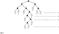
- Fig. 4
- illustrates another Huffman tree.
- In this example, let there be nine symbols S0, S1 ...S8 with the following respective frequencies of
occurrence Fig. 1 . - This Huffman tree can be represented as an ordered sequence of data structures as defined below in the following look-up tables (Tables 2, 3 and 4).
Table 2 Lookup table Offset_value Shift_value Sub_table Lookup table 0 0 2 0 Lookup table 1 12 0 1 Table 3 sub-table 0 y 0 1 2 3 4 5 6 7 symbol_locate ->S0 ->S1 ->S2 ->sub-table 1 ->S6 ->S6 ->S7 ->S8 Table 4 sub table 1 y 0 1 2 3 symbol locate -> S3 -> S4 -> S5 ->S5 - The first data structure (Table 2) is a first look-up table. It identifies an offset_value and shift_value pair to be used with each identified sub-table. In this example, it designates that a zero offset and shift_value of 2 should be used with sub-table 0 (Table 3) and that an offset_value of 12 and a shift_value of 0 should be used with sub-table 1 (Table 4).
- The second data structure (Table 3) is a look-up table. It is addressed using a value y and provides in return a value for symbol_locate. The value for symbol_locate may either point to a symbol value or point to another look-up table. For example, the values for y equal to 0, 1, 2, 4, 5, 6, 7 respectively point to the symbols S0, S1, S2, S6, S6, S7, S8 and the value for y equal to 3 points to sub-table 1 (Table 4).
- The third data structure (Table 4) is a look-up table. It is addressed using a value y and provides in return a value for symbol_locate. The value for symbol_locate may either point to a symbol value or point to another look-up table. In this example the values for y equal to 0, 1, 2, 3 respectively point to the symbols S3, S4, S5, S5.
- The 8-bit symbol_locate may be formatted so that its most significant bit (MSB) identifies whether it is a pointer to a symbol (MSB=0) or a pointer to another look-up table (MSB=1). Bits 1-7 gives an address of the correct symbol or look-up table. For example, the value of symbol_locate in sub-table0 at y=3 would be 1000 0001 indicating
sub-table 1. The value of symbol_locate in sub-table0 at y=1 would be 0000 0000 indicating symbol S0 according to Table 5 below.Table 5 symbol locate Symbol 0000 0000 S0 0000 0001 S1 0000 0010 S2 0000 0011 S3 0000 0100 S4 0000 0101 S5 0000 0110 S6 0000 0111 S7 0000 1000 S8 - The creation of the above described data structures will now be described. Table 6 illustrates the methodology used to create the data structures.
- In Table 6,
column 1 lists in order the symbols Si for i=0, 1, 2 ...N-1.Column 2 list adjacent each symbol its codeword.Column 3 gives the count value CountSi for each codeword. - CountSi is the value of the sequence of bits obtained by adding 1's to the codeword for symbol Si until it has a length H. For example, the count value for S0 is the value of 00011 (2+1), the count value of S2 is the value of 01011 (8+2+1). Alternatively the count value CountSi may be calculated, for each symbol Si occupying a level Li and a codeword of value V, as [(V+1)*2^ (H-Li)] -1. E.g. for S3 {01100}, V=12 & L=0, and count= [(12+1)*(2^0)]-1 = 12 and for S8 {111}, V=7 & L=2, and count = [(7+1)*(2^2)]-1= 31.
-
Column 4 gives a factor for each symbol. This is calculated, for symbol Si, as countSi - countSi-1, where countS-1 = -1 . It may alternatively be calculated, for Symbol Si at level Li, as 2^ (H-Li). -
Column 5 gives the 'shift' for each symbol. It is the logarithm to thebase 2 of the symbol's factor. The shift may alternatively be calculated, for each symbol Si, as Li.Table 6 1 2 3 4 5 6 7 8 9 Si Codeword CountSi Factor Shift y = (x-0) >> 2 y = (x-12) >> 0 2^(H-Li) H-Li S-1 -1 S0 000 3 (011) 4 2 0(0) - S1 001 7 (111) 4 2 1 (1) - S2 010 11 (1011) 4 2 2 (10) - S3 01100 12 (1100) 1 0 3 (11) 0 S4 01101 13 (1101) 1 0 3 (11) 1 S5 0111 15 (1111) 2 1 3 (11) 3 S6 10 23 (10111) 8 3 5 (101) - S7 110 27 (11011) 4 2 6 (110) - S8 111 31 (11111) 4 2 7 (111) - -
Equation 1 is used to calculate the values incolumns 6 and 7, which provide the content for the second and third data structures (Tables 3 and 4).
x is the value of a codeword, offset-value is an integer greater than or equal to 0, and shift value is an integer greater than or equal to 0. The operator ">>" indicates that the value (x - offset_value) should be truncated by shift_value, losing shift_value of its least significant bits. This shift operation to the left is equivalent to a divide by 2^shift_value operation but is easily performed by a digital signal processor (DSP). - For
column 6 i.e. the second data structure (Table 3) the offset_value is set to zero and the shift_value is set to 2. The equation y = (x - 0) >> 2 is used to calculate each of the entries incolumn 6, which correspond to y values in sub-table 0 (Table 3). The symbols S3, S4 and S5 share a common y value. A further sub-table is used for these symbols. - For column 7 i.e. the third data structure (Table 4) the offset_value is 12 and the shift-value is set to 0. The equation y = (x -12) >> 0 is used to calculate each of the entries in column 7 for unresolved symbols S3, S4 and S5, which correspond to the y values in sub-table 1 (Table 4).
- Consequently, the
sub-table 0 represents the nodes in the Huffman binary tree ofFig. 1 at a level Li that is shift_value levels removed from the top of the tree i.e.. Li= H-shift_value. - The nodes at L=3, in order are, S0, S1, S2, F2, empty, empty, S7, S8. The empty nodes would depend from a leaf node associated with symbol S6. The symbol S6 is therefore placed in the dependant empty nodes. The nodes at L=3, can be re-written as S0, S1, S2, F2, S6, S6, S7, S8. This corresponds to the content of the entries in
sub-table 0. - The internal node F2, is the root of a sub-tree. The sub-table 1 represents this sub-tree. The count value of any leaf nodes that depend from F2 will have values between 12 and 15. The count values of the codewords are renormalized by subtracting 12, the offset value for
sub-table 1. - The sub-table 1 represents the nodes of the sub-tree at a level L in the Huffman binary tree equal to H- shift_value. Shift_value, for
sub-table 1, is zero for this sub-tree so L=5. - The nodes at L=5 are, in order, S3, S4, empty, empty. The empty nodes would depend from a leaf node associated with symbol S5. The symbol S5 is therefore placed in the dependant empty nodes. The nodes at L=5 can be rewritten as S3, S4, S5, S5. This corresponds to the content of the entries in
sub-table 1. - The Huffman tree in
Fig. 1 is therefore represented by a first data structure, sub-table 0, representing the tree at level L=3 and by a second data structure, sub-table 1, representing a sub-tree at level L=5. - Sectioning the tree is necessary to allow the most probable symbols to be found first in an efficient manner. However, the introduction of too many sections uses additional memory to store the additional sub-table and additional shift and offset values and requires additional processing steps to decode the less commonly occurring symbols.
- For example, it is possible to represent the Huffman tree by sectioning it at different levels than L=3 and L=5. For example, if the tree is sectioned at L=3, L=4 and L=5, there will be three sub-tables. The first entry of the sub-table for L=4 will refer to the sub-table for L=5 and the second entry will refer to S5. The first entry of the sub-table for L=5 will refer to S3 and the second entry will refer to S4. The offset for both these sub-table is 12. The shift for the sub-table for L=4 is 1 and the shift for the sub-table for L=5 is 0.
- The following should be noted for the sectioning of the Huffman tree of
Fig. 1 that gave the data structures of Tables 2, 3, 4 and 5. - A data structure representing a level L of a tree (i.e. a tree sectioned at L) has a shift value equal to H-L. A data structure referenced from a node N in the tree, where the node N has a codeword value V and is in level L, has an offset_value V * 2^ (H-L).
- For the sub-tabte0, the shift value is set equivalent to H- L*, where L* is the level at which the tree is sectioned. Here it is the lowest level on which multiple leaves appear. In
Fig. 1 there is one leaf at L=2, but multiple leaves at L=3. Therefore the tree is sectioned at L=3 and the shift_value = 2. The offset_value is 0. - For example, the
sub-table 1 is referenced via node {011} at L=3. V=3, therefore the offset_value for the sub-table 1 is 3*2^2. The shift value for the sub-table1 is set equivalent to H- L*, where L* is the level at which the tree is sectioned. Here, it is the lowest level on which multiple leaves appear in the sub-tree. InFig. 1 the sub-tree has as its root F2 in level L=3. This sub-tree has one leaf at L=4, but two at L=5. Therefore the tree is sectioned at L=5 and shift_value = 0. -
Fig. 2 illustrates adevice 20 that is operable as an encoder. The encoder device comprises aprocessor 22 and amemory 24. Thememory 24 stores computer program instructions that control theprocessor 22 to carry-out the encoding process described above. - The computer program instructions may be transferred to the memory via a suitable storage medium in which the instructions are embodied or they may be transferred via electrical signals embodying the instructions.
- The
processor 22 has aninput 21 for receiving data for encoding and has anoutput 23 for providing encoded data. The encoded data includes a plurality of data structures representing a Huffman tree and a value for the height H of the tree. -
Fig 2 . illustrates adevice 20 operable an a decoder. The decoder comprises aprocessor 22 and amemory 24. The memory stores data structures representing a Huffman tree as described above. For example thememory 24 may store tables corresponding to those illustrated in Tables 2, 3, 4 and 5 above. The memory also stores computer program instructions that control theprocessor 22 to carry-out the decoding process described below with reference toFig. 3 . - The computer program instructions may be transferred to the memory via a suitable storage medium in which the instructions are embodied or they may be transferred via electrical signals embodying the instructions.
- The
processor 22 has aninput 21 for receiving data for decoding and has anoutput 23 for providing decoded data. The height of the Huffman tree is known in the decoder. This may be communicated to the decoder in a header provided with the data for decoding. - The decoder performs the following steps as illustrated in
Fig. 3 : - At
step 100 the current sub-table identifier z is set to zero. - Then at
step 102, H bits are extracted from the bitstream, having a value x - Then at
step 104, the look-up table is accessed. The offset_value and shift_value for sub-table z is obtained. - Then at
step 106, calculate a y value for the current sub-table fromequation 1 using x and the obtained values of offset_value and shift_value for the current sub-table. - Then at
step 108, access the current sub-table, sub-table z. Obtain the symbol_locate from sub-table z corresponding to the calculated y value. - Then at
step 110, a comparison is performed on the MSB of the obtained symbol_locate. If the MSB of the obtained symbol_locate is 0 then the process jumps to step 114 If the MSB of the obtained symbol_locate is 1, the process jumps to step 112. - At
step 112, the current sub-table identifier z is set equal to the remaining least significant bits of the symbol_locate obtained atstep 108. Then the process returns to step 104. - At
step 114, the symbol corresponding to by the symbol_locate obtained atstep 108. - An example of the process illustrated will now be given using the example look-up tables given above (Tables 2, 3, 4 and 5). The codeword to be searched is {0, 1, 1,1}. Let the extracted bits be {0, 1, 1, 1, 0}.
- At
step 100, set the current sub-table indicator z = 0 - At
step 102, extract bits{0, 1, 1, 1, 0}. Therefore x = 14. - At
step 104, access the look-up table (Table 2). The offset_value for sub-table 0 = 0 and the shift_value for sub-table 0 = 2. - At
step 106, calculatey using equation 1.
- At
step 108, access the current sub-table, sub-table 0 (Table 3). Obtain the symbol_locate from sub-table 0 corresponding to the calculated y value. The symbol_locate is {1000 0001}. - At
step 110, the MSB of the obtained symbol_locate is determined to be 1, therefore go to step 112. - At
step 112, z is set equal to the remaining least significant bits {000 0001} of the obtained symbol_locate i.e. z=1. - At
step 104, access the current look-up table (Table 2). Obtain a new offset_value and a new shift_value for the new current sub-table (sub-table 1). The offset_value for sub-table 1 = 12 and the shift_value for sub-table 1 = 0. - At
step 106, calculate y for current sub-table, sub-table 1, usingequation 1.
- At
step 108, access the current sub-table (sub-table 1). Obtain the symbol_locate corresponding to the new y value (y=2). The symbol_locate is {0000 0101}. - At
step 110, the MSB of the obtained symbol_locate is determined to be 0, therefore go to step 114. - At
step 114, obtain the symbol corresponding to the obtained symbol_locate.
The symbol corresponding to the obtained symbol_locate {0000 0101} is, from Table 5, S5. - It will be understood that the same result will be achieved if the extracted bits are {0, 1, 1,1,1} instead of {0, 1, 1, 1, 0}.
- As a further illustration the encoding of the Huffman tree illustrated in
Fig. 4 will now be briefly described.Table 7 is created: Si codeword countSi S0 000 15 S1 001 31 S2 010 47 S3 01100 51 S4 0110100 52 S5 0110101 53 S6 011011 55 S7 0111 63 S8 10 95 S9 110 111 S10 111 127 y0 0 1 2 3 4 5 6 7 symbol locate S0 S1 S2 Goto table1 S8 S8 S9 S10 y1 0 1 symbol_locate Goto table2 S7 y2 0 1 symbol_locate S3 Goto table3 y3 0 1 2 3 symbol_locate S4 S5 S6 S6 - Although the present invention has been described with reference to various particular examples, it should be understood the various variations and modification can be made without departing from the scope of the invention, as defined by the claims.
Claims (21)
- A decoder (20) for decoding a bitstream encoded according to a Huffman coding tree (10) of height H comprising:a memory (24) for storing a plurality of data structures representing the Huffman coding tree (10) of height H including at least a first data structure representing a first level of the Huffman coding tree used to encode the bitstream and having an associated first offset value and an associated first shift value and a second data structure representing a second, different level of the Huffman coding tree used to encode the bitstream andhaving an associated second offset value and an associated second shift value; anda processor (22) configured to:subtract the first offset value from a codeword of H bits taken from the bitstream; right shift the result by the first shift value; andaddress the first data structure using the shifted result to identify either a symbol or the second data structure;if the second data structure is identified using the first data structure:subtract the second offset value from the codeword of H bits; right shift the result by the second shift value; andaddress the second data structure using the shifted result to identify either a symbol or a third data structure representing a third, different level of the Huffman coding tree used to encode the bitstream.
- A decoder (20) as claimed in claim 1, wherein the first data structure represents a first level of the Huffman coding tree (10) and the second data structure represents a second, lower level of the Huffman coding tree (10).
- A decoder (20) as claimed in claim 2, wherein the first shift value corresponds to the first level.
- A decoder (20) as claimed in claim 2 or 3, wherein the second shift value corresponds to the second level.
- A decoder (20) as claimed in claim 2, 3 or 4 wherein the second offset value identifies a position of a first sub-tree within the Huffman tree (10).
- A decoder (20) as claimed in any one of claims 3 to 5, wherein the processor (22) is configured, having obtained a value from addressing the associated data structure, to perform a comparison using that value and in dependence upon the comparison either use the value to identify a symbol or a new current offset value.
- A decoder (20) as claimed in claim 6, wherein the comparison uses the most significant bit of the value.
- A decoder (20) as claimed in claim 6 or 7, wherein the offset value is initially set to the first offset value.
- A storage medium or transmission medium embodying data representing a Huffman coding tree (10) comprising leaf nodes and interior nodes arranged in H levels, wherein a leaf node depends from a single interior node on the next lowest level and represents a symbol and wherein an interior node depends from a single interior node on the next lowest level, the data comprising:a first data structure identifying, for each of the nodes within a first specified level of the tree (10), a symbol for each leaf node and a further data structure for each interior node; at least a second data structure, identified by the first data structure, identifying for each of the nodes within a sub-tree, depending from a first interior node in the first data structure and at a second specified level of the tree (10), a symbol for each leaf node and a further data structure for any interior node; anda first single offset value and a first single shift value that is associated with all of the nodes of the first level and a second single offset value and a second single shift value that is associated with all of the nodes of the second level, wherein the first specified level is the level that is first single shift value levels removed from the top of the Huffman coding tree and the second specified level is the level that is second single shift value levels removed from the top of the Huffman coding tree, wherein the top of the Huffman coding tree is the height H of the Huffman coding tree.
- A storage medium or transmission medium as claimed in claim 9, wherein the first data structure identifies a symbol for each empty node, if any, wherein an empty node is a node that would depend from a leaf node on the next lowest level.
- A storage medium or transmission medium as claimed in claim 9 or 10, wherein the second data structure identifies a symbol for each empty node of a sub-tree at a second level of the tree (10), wherein an empty node is a node that would depend from a leaf node on the next lowest level.
- A storage medium or transmission medium as claimed in claim 9, 10 or 11 wherein the first level is the lowest level within the tree (10) with at least two leaf nodes.
- A storage medium or transmission medium as claimed in any one of claims 9 to 12, wherein the second level is the lowest level within the sub-tree with at least two leaf nodes.
- A storage medium or transmission medium as claimed in any one of claim 9 to 13, wherein the first interior node, when at level L (L=0, 1,2..) and having a value V, is specifying by a value dependent upon V*2^(H-L).
- A storage medium or transmission medium as claimed in any one of claims 9 to 14, further comprising data specifying H.
- A method of decoding a bitstream encoded according to a Huffman coding tree (10) of height H comprising:subtracting a first offset value from a codeword of H bits taken from a bitstream; right shifting the result by a furst shift value; andaddressing a first data structure using the shifted result to identify either a symbol or a second data structure; and if the second data structure is identified using the first data structure:subtracting a second offset value from the codeword of H bits; right shift the result by a second shift value; andaddress the second data structure using the result to identify either a symbol or a third data structure,wherein the first offset value and first shift value are associated with a first data structure representing a first level of the Huffman coding tree (10) of height H used to encode the bitstream and the second offset value and second shift value are associated with a second data structure representing a second, different level of the Huffman coding tree (10) of height H used to encode the bitstream.
- A method as claimed in claim 16, further comprising accessing a look-up table to obtain the offset values and the shift values.
- A method as claimed in claim 16 or 17, wherein the addressed data structure represents a first level of the Huffman coding tree (10).
- A method as claimed in any of claims 16 to 18, further comprising receiving at least the value of height H, the offset value, the shift value and the data structure.
- A computer program that, when executed by a processor, performs the method of any of claims 16 to 19.
- A storage medium or transmission medium embodying the computer program of claim 20.
Applications Claiming Priority (1)
| Application Number | Priority Date | Filing Date | Title |
|---|---|---|---|
| PCT/IB2003/004310 WO2005022754A1 (en) | 2003-09-02 | 2003-09-02 | Huffman coding and decoding |
Publications (2)
| Publication Number | Publication Date |
|---|---|
| EP1645037A1 EP1645037A1 (en) | 2006-04-12 |
| EP1645037B1 true EP1645037B1 (en) | 2017-05-24 |
Family
ID=34259882
Family Applications (1)
| Application Number | Title | Priority Date | Filing Date |
|---|---|---|---|
| EP03753835.2A Expired - Lifetime EP1645037B1 (en) | 2003-09-02 | 2003-09-02 | Huffman decoding |
Country Status (5)
| Country | Link |
|---|---|
| US (1) | US7358870B2 (en) |
| EP (1) | EP1645037B1 (en) |
| CN (1) | CN100546201C (en) |
| AU (1) | AU2003271995A1 (en) |
| WO (1) | WO2005022754A1 (en) |
Families Citing this family (19)
| Publication number | Priority date | Publication date | Assignee | Title |
|---|---|---|---|---|
| US7458022B2 (en) * | 2003-10-22 | 2008-11-25 | Intel Corporation | Hardware/software partition for high performance structured data transformation |
| US9083972B2 (en) * | 2005-07-20 | 2015-07-14 | Humax Holdings Co., Ltd. | Encoder and decoder |
| US8457304B2 (en) * | 2007-02-23 | 2013-06-04 | Choy Sai Foundation L.L.C. | Efficient encoding processes and apparatus |
| US7642935B2 (en) * | 2008-04-07 | 2010-01-05 | Mediatek Inc. | Huffman decoding method and apparatus |
| CN101626242B (en) * | 2008-07-11 | 2014-04-16 | 数维科技(北京)有限公司 | Improved Huffman decoding method and device |
| US7663512B2 (en) * | 2008-07-21 | 2010-02-16 | Hon Hai Precision Industry Co., Ltd. | Decoder and method for decoding a message using an arbitrary-side growing Huffman tree |
| JP5062131B2 (en) * | 2008-10-06 | 2012-10-31 | 富士通株式会社 | Information processing program, information processing apparatus, and information processing method |
| US7796059B2 (en) * | 2009-01-16 | 2010-09-14 | Tatu Ylonen Oy | Fast approximate dynamic Huffman coding with periodic regeneration and precomputing |
| US8321326B2 (en) | 2009-09-15 | 2012-11-27 | Auerbach Group Llc | Method and system for enhancing the efficiency of a digitally communicated data exchange |
| US8593308B1 (en) * | 2012-05-31 | 2013-11-26 | International Business Machines Corporation | Method of accelerating dynamic Huffman decompaction within the inflate algorithm |
| CN103905054B (en) * | 2012-12-25 | 2017-05-24 | 展讯通信(上海)有限公司 | Code table establishing method and device, and encoding and decoding method and device |
| US9413388B1 (en) * | 2015-01-30 | 2016-08-09 | Dell Products L.P. | Modified huffman decoding |
| CN105933704B (en) * | 2016-04-15 | 2019-02-12 | 杨桦 | One kind being based on the decoded method and apparatus of Huffman |
| CN106253910A (en) * | 2016-09-22 | 2016-12-21 | 山东华旗新能源科技有限公司 | A kind of compaction coding method |
| US9698819B1 (en) * | 2016-12-23 | 2017-07-04 | Amazon Technologies, Inc. | Huffman code generation |
| CN107565973B (en) * | 2017-08-01 | 2020-07-14 | 中国人民解放军国防科学技术大学 | Method for realizing node-extensible Huffman coding and circuit structure |
| US10693493B1 (en) | 2019-02-14 | 2020-06-23 | International Business Machines Corporation | Reducing latch count to save hardware area for dynamic Huffman table generation |
| US10944423B2 (en) | 2019-03-14 | 2021-03-09 | International Business Machines Corporation | Verifying the correctness of a deflate compression accelerator |
| CN119995833B (en) * | 2025-04-15 | 2025-06-27 | 江阴众和电力仪表有限公司 | Data encryption method for electric energy meter |
Citations (1)
| Publication number | Priority date | Publication date | Assignee | Title |
|---|---|---|---|---|
| EP1130926A2 (en) * | 2000-03-03 | 2001-09-05 | Texas Instruments Incorporated | Variable length decoding system and method |
Family Cites Families (11)
| Publication number | Priority date | Publication date | Assignee | Title |
|---|---|---|---|---|
| US4821290A (en) * | 1988-02-09 | 1989-04-11 | General Electric Company | Decoder for digital signal codes |
| US5550542A (en) * | 1994-05-04 | 1996-08-27 | Matsushita Electric Corporation Of America | Variable length code look-up table having separate code length determination |
| US5541595A (en) * | 1994-05-19 | 1996-07-30 | Matsushita Electric Corporation Of America | Variable length code decoder for simultaneous decoding the most significant bits and the least significant bits of a variable length code |
| US6188797B1 (en) * | 1997-05-27 | 2001-02-13 | Apple Computer, Inc. | Decoder for programmable variable length data |
| US5955980A (en) * | 1997-10-03 | 1999-09-21 | Motorola, Inc. | Circuit and method for calibrating a digital-to-analog converter |
| US5973626A (en) * | 1998-03-17 | 1999-10-26 | Cornell Research Foundation, Inc. | Byte-based prefix encoding |
| US6603413B2 (en) * | 2001-02-07 | 2003-08-05 | Canon Kabushiki Kaisha | Variable-length decoding apparatus and method |
| KR100484137B1 (en) | 2002-02-28 | 2005-04-18 | 삼성전자주식회사 | Improved huffman decoding method and apparatus thereof |
| US6661358B1 (en) * | 2002-09-17 | 2003-12-09 | Enroute, Inc. | Decoding variable length codes without conditional branching |
| GB2409061B (en) * | 2003-12-09 | 2006-09-13 | Advanced Risc Mach Ltd | Table lookup operation within a data processing system |
| US7113115B2 (en) * | 2004-06-30 | 2006-09-26 | Intel Corporation | Variable length code table look ups |
-
2003
- 2003-09-02 CN CNB038270145A patent/CN100546201C/en not_active Expired - Lifetime
- 2003-09-02 US US10/568,009 patent/US7358870B2/en not_active Expired - Lifetime
- 2003-09-02 EP EP03753835.2A patent/EP1645037B1/en not_active Expired - Lifetime
- 2003-09-02 AU AU2003271995A patent/AU2003271995A1/en not_active Abandoned
- 2003-09-02 WO PCT/IB2003/004310 patent/WO2005022754A1/en not_active Ceased
Patent Citations (1)
| Publication number | Priority date | Publication date | Assignee | Title |
|---|---|---|---|---|
| EP1130926A2 (en) * | 2000-03-03 | 2001-09-05 | Texas Instruments Incorporated | Variable length decoding system and method |
Non-Patent Citations (2)
| Title |
|---|
| ALISTAIR MOFFAT ET AL: "On the Implementation of Minimum Redundancy Prefix Codes", IEEE TRANSACTIONS ON COMMUNICATIONS, IEEE SERVICE CENTER, PISCATAWAY, NJ, US, vol. 45, no. 10, 1 October 1997 (1997-10-01), XP011009043, ISSN: 0090-6778 * |
| HASHEMIAN R: "DESIGN AND HARDWARE IMPLEMENTATION OF A MEMORY EFFICIENT HUFFMAN DECODING", IEEE TRANSACTIONS ON CONSUMER ELECTRONICS, IEEE SERVICE CENTER, NEW YORK, NY, US, vol. 40, no. 3, 1 August 1994 (1994-08-01), pages 345 - 352, XP000471193, ISSN: 0098-3063, DOI: 10.1109/30.320814 * |
Also Published As
| Publication number | Publication date |
|---|---|
| US20060290537A1 (en) | 2006-12-28 |
| AU2003271995A1 (en) | 2005-03-16 |
| CN100546201C (en) | 2009-09-30 |
| EP1645037A1 (en) | 2006-04-12 |
| US7358870B2 (en) | 2008-04-15 |
| CN1826732A (en) | 2006-08-30 |
| WO2005022754A1 (en) | 2005-03-10 |
Similar Documents
| Publication | Publication Date | Title |
|---|---|---|
| US7358870B2 (en) | Huffman coding and decoding based upon sectioning of a Huffman coding tree | |
| US5455577A (en) | Method and system for data compression | |
| US5450562A (en) | Cache-based data compression/decompression | |
| US5572206A (en) | Data compression method and system | |
| US6286053B1 (en) | Method, client device, server and article of manufacture for compressing universal resource indicators using partitioned left/right string substitution | |
| US6633242B2 (en) | Entropy coding using adaptable prefix codes | |
| US6606040B2 (en) | Method and apparatus for adaptive data compression | |
| US7028039B2 (en) | System and method for storing connectivity information in a web database | |
| EP0903866B1 (en) | Method and apparatus for data compression | |
| US7446681B2 (en) | Lookup table array compression and indexing | |
| CN108696492B (en) | Method and device for processing IP message | |
| EP0983635B1 (en) | Arithmetic encoding and decoding of an information signal | |
| JPH1079672A (en) | Method and device for compressing and decompressing message | |
| JPS6356726B2 (en) | ||
| US5808572A (en) | Method and apparatus for finite-length arithmetic coding | |
| KR100906041B1 (en) | Font compression and retrieval method and apparatus | |
| EP3886324B1 (en) | Compression and/or decompression of activation data | |
| EP0658982B1 (en) | System for bi-level symbol coding-decoding with saved storage and method for the same | |
| EP1636997A1 (en) | A method and system for decoding variable length encoded signals, computer program product therefor | |
| JP3080149B2 (en) | Pattern encoding method and decoding method, and encoding apparatus and decoding apparatus using the method | |
| CN100471279C (en) | A Method Based on Context Adaptive Variable Length Decoding | |
| KR100840757B1 (en) | Huffman Coding and Decoding | |
| JP2001267931A (en) | Variable length decoding system and method | |
| US10084477B2 (en) | Method and apparatus for adaptive data compression | |
| Padmanabhan | Operations for Text Processing |
Legal Events
| Date | Code | Title | Description |
|---|---|---|---|
| PUAI | Public reference made under article 153(3) epc to a published international application that has entered the european phase |
Free format text: ORIGINAL CODE: 0009012 |
|
| 17P | Request for examination filed |
Effective date: 20060117 |
|
| AK | Designated contracting states |
Kind code of ref document: A1 Designated state(s): AT BE BG CH CY CZ DE DK EE ES FI FR GB GR HU IE IT LI LU MC NL PT RO SE SI SK TR |
|
| DAX | Request for extension of the european patent (deleted) | ||
| 17Q | First examination report despatched |
Effective date: 20110119 |
|
| RAP1 | Party data changed (applicant data changed or rights of an application transferred) |
Owner name: NOKIA CORPORATION |
|
| RAP1 | Party data changed (applicant data changed or rights of an application transferred) |
Owner name: NOKIA TECHNOLOGIES OY |
|
| GRAP | Despatch of communication of intention to grant a patent |
Free format text: ORIGINAL CODE: EPIDOSNIGR1 |
|
| INTG | Intention to grant announced |
Effective date: 20161219 |
|
| GRAS | Grant fee paid |
Free format text: ORIGINAL CODE: EPIDOSNIGR3 |
|
| GRAA | (expected) grant |
Free format text: ORIGINAL CODE: 0009210 |
|
| RAP1 | Party data changed (applicant data changed or rights of an application transferred) |
Owner name: HMD GLOBAL OY |
|
| AK | Designated contracting states |
Kind code of ref document: B1 Designated state(s): AT BE BG CH CY CZ DE DK EE ES FI FR GB GR HU IE IT LI LU MC NL PT RO SE SI SK TR |
|
| REG | Reference to a national code |
Ref country code: GB Ref legal event code: FG4D |
|
| REG | Reference to a national code |
Ref country code: CH Ref legal event code: EP |
|
| REG | Reference to a national code |
Ref country code: IE Ref legal event code: FG4D |
|
| REG | Reference to a national code |
Ref country code: AT Ref legal event code: REF Ref document number: 896456 Country of ref document: AT Kind code of ref document: T Effective date: 20170615 |
|
| REG | Reference to a national code |
Ref country code: DE Ref legal event code: R096 Ref document number: 60350263 Country of ref document: DE |
|
| REG | Reference to a national code |
Ref country code: NL Ref legal event code: MP Effective date: 20170524 |
|
| REG | Reference to a national code |
Ref country code: FR Ref legal event code: PLFP Year of fee payment: 15 |
|
| REG | Reference to a national code |
Ref country code: AT Ref legal event code: MK05 Ref document number: 896456 Country of ref document: AT Kind code of ref document: T Effective date: 20170524 |
|
| PG25 | Lapsed in a contracting state [announced via postgrant information from national office to epo] |
Ref country code: FI Free format text: LAPSE BECAUSE OF FAILURE TO SUBMIT A TRANSLATION OF THE DESCRIPTION OR TO PAY THE FEE WITHIN THE PRESCRIBED TIME-LIMIT Effective date: 20170524 Ref country code: AT Free format text: LAPSE BECAUSE OF FAILURE TO SUBMIT A TRANSLATION OF THE DESCRIPTION OR TO PAY THE FEE WITHIN THE PRESCRIBED TIME-LIMIT Effective date: 20170524 Ref country code: ES Free format text: LAPSE BECAUSE OF FAILURE TO SUBMIT A TRANSLATION OF THE DESCRIPTION OR TO PAY THE FEE WITHIN THE PRESCRIBED TIME-LIMIT Effective date: 20170524 Ref country code: GR Free format text: LAPSE BECAUSE OF FAILURE TO SUBMIT A TRANSLATION OF THE DESCRIPTION OR TO PAY THE FEE WITHIN THE PRESCRIBED TIME-LIMIT Effective date: 20170825 |
|
| PG25 | Lapsed in a contracting state [announced via postgrant information from national office to epo] |
Ref country code: BG Free format text: LAPSE BECAUSE OF FAILURE TO SUBMIT A TRANSLATION OF THE DESCRIPTION OR TO PAY THE FEE WITHIN THE PRESCRIBED TIME-LIMIT Effective date: 20170824 Ref country code: SE Free format text: LAPSE BECAUSE OF FAILURE TO SUBMIT A TRANSLATION OF THE DESCRIPTION OR TO PAY THE FEE WITHIN THE PRESCRIBED TIME-LIMIT Effective date: 20170524 Ref country code: NL Free format text: LAPSE BECAUSE OF FAILURE TO SUBMIT A TRANSLATION OF THE DESCRIPTION OR TO PAY THE FEE WITHIN THE PRESCRIBED TIME-LIMIT Effective date: 20170524 |
|
| PG25 | Lapsed in a contracting state [announced via postgrant information from national office to epo] |
Ref country code: CZ Free format text: LAPSE BECAUSE OF FAILURE TO SUBMIT A TRANSLATION OF THE DESCRIPTION OR TO PAY THE FEE WITHIN THE PRESCRIBED TIME-LIMIT Effective date: 20170524 Ref country code: RO Free format text: LAPSE BECAUSE OF FAILURE TO SUBMIT A TRANSLATION OF THE DESCRIPTION OR TO PAY THE FEE WITHIN THE PRESCRIBED TIME-LIMIT Effective date: 20170524 Ref country code: DK Free format text: LAPSE BECAUSE OF FAILURE TO SUBMIT A TRANSLATION OF THE DESCRIPTION OR TO PAY THE FEE WITHIN THE PRESCRIBED TIME-LIMIT Effective date: 20170524 Ref country code: EE Free format text: LAPSE BECAUSE OF FAILURE TO SUBMIT A TRANSLATION OF THE DESCRIPTION OR TO PAY THE FEE WITHIN THE PRESCRIBED TIME-LIMIT Effective date: 20170524 Ref country code: SK Free format text: LAPSE BECAUSE OF FAILURE TO SUBMIT A TRANSLATION OF THE DESCRIPTION OR TO PAY THE FEE WITHIN THE PRESCRIBED TIME-LIMIT Effective date: 20170524 |
|
| REG | Reference to a national code |
Ref country code: DE Ref legal event code: R097 Ref document number: 60350263 Country of ref document: DE |
|
| PG25 | Lapsed in a contracting state [announced via postgrant information from national office to epo] |
Ref country code: IT Free format text: LAPSE BECAUSE OF FAILURE TO SUBMIT A TRANSLATION OF THE DESCRIPTION OR TO PAY THE FEE WITHIN THE PRESCRIBED TIME-LIMIT Effective date: 20170524 |
|
| PLBE | No opposition filed within time limit |
Free format text: ORIGINAL CODE: 0009261 |
|
| STAA | Information on the status of an ep patent application or granted ep patent |
Free format text: STATUS: NO OPPOSITION FILED WITHIN TIME LIMIT |
|
| REG | Reference to a national code |
Ref country code: CH Ref legal event code: PL |
|
| 26N | No opposition filed |
Effective date: 20180227 |
|
| PG25 | Lapsed in a contracting state [announced via postgrant information from national office to epo] |
Ref country code: MC Free format text: LAPSE BECAUSE OF FAILURE TO SUBMIT A TRANSLATION OF THE DESCRIPTION OR TO PAY THE FEE WITHIN THE PRESCRIBED TIME-LIMIT Effective date: 20170524 Ref country code: SI Free format text: LAPSE BECAUSE OF FAILURE TO SUBMIT A TRANSLATION OF THE DESCRIPTION OR TO PAY THE FEE WITHIN THE PRESCRIBED TIME-LIMIT Effective date: 20170524 |
|
| REG | Reference to a national code |
Ref country code: IE Ref legal event code: MM4A |
|
| REG | Reference to a national code |
Ref country code: BE Ref legal event code: MM Effective date: 20170930 |
|
| PG25 | Lapsed in a contracting state [announced via postgrant information from national office to epo] |
Ref country code: LU Free format text: LAPSE BECAUSE OF NON-PAYMENT OF DUE FEES Effective date: 20170902 |
|
| PG25 | Lapsed in a contracting state [announced via postgrant information from national office to epo] |
Ref country code: IE Free format text: LAPSE BECAUSE OF NON-PAYMENT OF DUE FEES Effective date: 20170902 Ref country code: LI Free format text: LAPSE BECAUSE OF NON-PAYMENT OF DUE FEES Effective date: 20170930 Ref country code: CH Free format text: LAPSE BECAUSE OF NON-PAYMENT OF DUE FEES Effective date: 20170930 |
|
| PG25 | Lapsed in a contracting state [announced via postgrant information from national office to epo] |
Ref country code: BE Free format text: LAPSE BECAUSE OF NON-PAYMENT OF DUE FEES Effective date: 20170930 |
|
| REG | Reference to a national code |
Ref country code: FR Ref legal event code: PLFP Year of fee payment: 16 |
|
| PG25 | Lapsed in a contracting state [announced via postgrant information from national office to epo] |
Ref country code: HU Free format text: LAPSE BECAUSE OF FAILURE TO SUBMIT A TRANSLATION OF THE DESCRIPTION OR TO PAY THE FEE WITHIN THE PRESCRIBED TIME-LIMIT; INVALID AB INITIO Effective date: 20030902 |
|
| PG25 | Lapsed in a contracting state [announced via postgrant information from national office to epo] |
Ref country code: CY Free format text: LAPSE BECAUSE OF NON-PAYMENT OF DUE FEES Effective date: 20170524 |
|
| PG25 | Lapsed in a contracting state [announced via postgrant information from national office to epo] |
Ref country code: TR Free format text: LAPSE BECAUSE OF FAILURE TO SUBMIT A TRANSLATION OF THE DESCRIPTION OR TO PAY THE FEE WITHIN THE PRESCRIBED TIME-LIMIT Effective date: 20170524 |
|
| PG25 | Lapsed in a contracting state [announced via postgrant information from national office to epo] |
Ref country code: PT Free format text: LAPSE BECAUSE OF FAILURE TO SUBMIT A TRANSLATION OF THE DESCRIPTION OR TO PAY THE FEE WITHIN THE PRESCRIBED TIME-LIMIT Effective date: 20170524 |
|
| PGFP | Annual fee paid to national office [announced via postgrant information from national office to epo] |
Ref country code: GB Payment date: 20220920 Year of fee payment: 20 Ref country code: DE Payment date: 20220920 Year of fee payment: 20 |
|
| PGFP | Annual fee paid to national office [announced via postgrant information from national office to epo] |
Ref country code: FR Payment date: 20220922 Year of fee payment: 20 |
|
| REG | Reference to a national code |
Ref country code: DE Ref legal event code: R071 Ref document number: 60350263 Country of ref document: DE |
|
| REG | Reference to a national code |
Ref country code: GB Ref legal event code: PE20 Expiry date: 20230901 |
|
| PG25 | Lapsed in a contracting state [announced via postgrant information from national office to epo] |
Ref country code: GB Free format text: LAPSE BECAUSE OF EXPIRATION OF PROTECTION Effective date: 20230901 |