EP1644683B1 - Heat exchanger tube - Google Patents
Heat exchanger tube Download PDFInfo
- Publication number
- EP1644683B1 EP1644683B1 EP04773831.5A EP04773831A EP1644683B1 EP 1644683 B1 EP1644683 B1 EP 1644683B1 EP 04773831 A EP04773831 A EP 04773831A EP 1644683 B1 EP1644683 B1 EP 1644683B1
- Authority
- EP
- European Patent Office
- Prior art keywords
- beads
- refrigerant
- heat exchanger
- channel
- exchanger tube
- Prior art date
- Legal status (The legal status is an assumption and is not a legal conclusion. Google has not performed a legal analysis and makes no representation as to the accuracy of the status listed.)
- Expired - Lifetime
Links
Images




Classifications
-
- F—MECHANICAL ENGINEERING; LIGHTING; HEATING; WEAPONS; BLASTING
- F28—HEAT EXCHANGE IN GENERAL
- F28F—DETAILS OF HEAT-EXCHANGE AND HEAT-TRANSFER APPARATUS, OF GENERAL APPLICATION
- F28F13/00—Arrangements for modifying heat-transfer, e.g. increasing, decreasing
- F28F13/06—Arrangements for modifying heat-transfer, e.g. increasing, decreasing by affecting the pattern of flow of the heat-exchange media
- F28F13/12—Arrangements for modifying heat-transfer, e.g. increasing, decreasing by affecting the pattern of flow of the heat-exchange media by creating turbulence, e.g. by stirring, by increasing the force of circulation
-
- F—MECHANICAL ENGINEERING; LIGHTING; HEATING; WEAPONS; BLASTING
- F28—HEAT EXCHANGE IN GENERAL
- F28F—DETAILS OF HEAT-EXCHANGE AND HEAT-TRANSFER APPARATUS, OF GENERAL APPLICATION
- F28F3/00—Plate-like or laminated elements; Assemblies of plate-like or laminated elements
- F28F3/02—Elements or assemblies thereof with means for increasing heat-transfer area, e.g. with fins, with recesses, with corrugations
- F28F3/04—Elements or assemblies thereof with means for increasing heat-transfer area, e.g. with fins, with recesses, with corrugations the means being integral with the element
- F28F3/042—Elements or assemblies thereof with means for increasing heat-transfer area, e.g. with fins, with recesses, with corrugations the means being integral with the element in the form of local deformations of the element
- F28F3/044—Elements or assemblies thereof with means for increasing heat-transfer area, e.g. with fins, with recesses, with corrugations the means being integral with the element in the form of local deformations of the element the deformations being pontual, e.g. dimples
-
- F—MECHANICAL ENGINEERING; LIGHTING; HEATING; WEAPONS; BLASTING
- F28—HEAT EXCHANGE IN GENERAL
- F28D—HEAT-EXCHANGE APPARATUS, NOT PROVIDED FOR IN ANOTHER SUBCLASS, IN WHICH THE HEAT-EXCHANGE MEDIA DO NOT COME INTO DIRECT CONTACT
- F28D1/00—Heat-exchange apparatus having stationary conduit assemblies for one heat-exchange medium only, the media being in contact with different sides of the conduit wall, in which the other heat-exchange medium is a large body of fluid, e.g. domestic or motor car radiators
- F28D1/02—Heat-exchange apparatus having stationary conduit assemblies for one heat-exchange medium only, the media being in contact with different sides of the conduit wall, in which the other heat-exchange medium is a large body of fluid, e.g. domestic or motor car radiators with heat-exchange conduits immersed in the body of fluid
- F28D1/03—Heat-exchange apparatus having stationary conduit assemblies for one heat-exchange medium only, the media being in contact with different sides of the conduit wall, in which the other heat-exchange medium is a large body of fluid, e.g. domestic or motor car radiators with heat-exchange conduits immersed in the body of fluid with plate-like or laminated conduits
- F28D1/0308—Heat-exchange apparatus having stationary conduit assemblies for one heat-exchange medium only, the media being in contact with different sides of the conduit wall, in which the other heat-exchange medium is a large body of fluid, e.g. domestic or motor car radiators with heat-exchange conduits immersed in the body of fluid with plate-like or laminated conduits the conduits being formed by paired plates touching each other
- F28D1/0325—Heat-exchange apparatus having stationary conduit assemblies for one heat-exchange medium only, the media being in contact with different sides of the conduit wall, in which the other heat-exchange medium is a large body of fluid, e.g. domestic or motor car radiators with heat-exchange conduits immersed in the body of fluid with plate-like or laminated conduits the conduits being formed by paired plates touching each other the plates having lateral openings therein for circulation of the heat-exchange medium from one conduit to another
- F28D1/0333—Heat-exchange apparatus having stationary conduit assemblies for one heat-exchange medium only, the media being in contact with different sides of the conduit wall, in which the other heat-exchange medium is a large body of fluid, e.g. domestic or motor car radiators with heat-exchange conduits immersed in the body of fluid with plate-like or laminated conduits the conduits being formed by paired plates touching each other the plates having lateral openings therein for circulation of the heat-exchange medium from one conduit to another the plates having integrated connecting members
- F28D1/0341—Heat-exchange apparatus having stationary conduit assemblies for one heat-exchange medium only, the media being in contact with different sides of the conduit wall, in which the other heat-exchange medium is a large body of fluid, e.g. domestic or motor car radiators with heat-exchange conduits immersed in the body of fluid with plate-like or laminated conduits the conduits being formed by paired plates touching each other the plates having lateral openings therein for circulation of the heat-exchange medium from one conduit to another the plates having integrated connecting members with U-flow or serpentine-flow inside the conduits
-
- F—MECHANICAL ENGINEERING; LIGHTING; HEATING; WEAPONS; BLASTING
- F28—HEAT EXCHANGE IN GENERAL
- F28F—DETAILS OF HEAT-EXCHANGE AND HEAT-TRANSFER APPARATUS, OF GENERAL APPLICATION
- F28F9/00—Casings; Header boxes; Auxiliary supports for elements; Auxiliary members within casings
- F28F9/02—Header boxes; End plates
- F28F9/026—Header boxes; End plates with static flow control means, e.g. with means for uniformly distributing heat exchange media into conduits
- F28F9/0282—Header boxes; End plates with static flow control means, e.g. with means for uniformly distributing heat exchange media into conduits by varying the geometry of conduit ends, e.g. by using inserts or attachments for modifying the pattern of flow at the conduit inlet or outlet
-
- F—MECHANICAL ENGINEERING; LIGHTING; HEATING; WEAPONS; BLASTING
- F28—HEAT EXCHANGE IN GENERAL
- F28D—HEAT-EXCHANGE APPARATUS, NOT PROVIDED FOR IN ANOTHER SUBCLASS, IN WHICH THE HEAT-EXCHANGE MEDIA DO NOT COME INTO DIRECT CONTACT
- F28D21/00—Heat-exchange apparatus not covered by any of the groups F28D1/00 - F28D20/00
- F28D2021/0019—Other heat exchangers for particular applications; Heat exchange systems not otherwise provided for
- F28D2021/0068—Other heat exchangers for particular applications; Heat exchange systems not otherwise provided for for refrigerant cycles
- F28D2021/0071—Evaporators
-
- F—MECHANICAL ENGINEERING; LIGHTING; HEATING; WEAPONS; BLASTING
- F28—HEAT EXCHANGE IN GENERAL
- F28F—DETAILS OF HEAT-EXCHANGE AND HEAT-TRANSFER APPARATUS, OF GENERAL APPLICATION
- F28F2215/00—Fins
- F28F2215/04—Assemblies of fins having different features, e.g. with different fin densities
-
- F—MECHANICAL ENGINEERING; LIGHTING; HEATING; WEAPONS; BLASTING
- F28—HEAT EXCHANGE IN GENERAL
- F28F—DETAILS OF HEAT-EXCHANGE AND HEAT-TRANSFER APPARATUS, OF GENERAL APPLICATION
- F28F2250/00—Arrangements for modifying the flow of the heat exchange media, e.g. flow guiding means; Particular flow patterns
- F28F2250/02—Streamline-shaped elements
Definitions
- the present invention relates to a heat exchanger tube more particularly, in which a number of beads for imparting turbulence to refrigerant flowing through a channel of a tube are formed streamlined and guide beads are formed in refrigerant distributing sections in order to reduce the amount of the pressure drop of refrigerant while realizing uniform refrigerant distribution.
- a heat exchanger refers to a device in which an interior refrigerant passage is formed so that refrigerant exchanges heat with external air while being circulated through the refrigerant passage.
- the heat exchanger is used in various air conditioning devices, and is employed in various forms such as a fin tube type, a serpentine type, a drawn cup type and a parallel flow type according to various conditions in which it is used.
- the heat exchanger has an evaporator-using refrigerant as heat exchange medium, which is divided into one-, two-and four-tank types:
- tubes formed by coupling one-tank plate pairs each having a pair of cups formed at one end and a U-shaped channel defined by an inside separator are laminated alternately with heat radiation fins.
- tubes formed by coupling two-tank plate pairs each having cups formed at the top and bottom are laminated alternately with heat radiation fins.
- tubes formed by coupling four-tank plate pairs each having cup pairs formed at the top and bottom and two channels divided by a separator are laminated alternately with heat radiation fins.
- the one-tank type heat exchanger includes a pair of parallel tanks 40 placed at the top of the exchanger and having parallel cups 14 and holes 14a formed in the cups 14, tubes 10 each formed by welding two single or double head plates 11 having a predetermined length of separators 13 extended from between the pair of tanks 40 to define a generally U-shaped channels 12 in which the tanks 40 are coupled together at both sides of the each tube 10, heat radiation fins 50 laminated between the tubes 10 and two end plates 30 provided at the outermost sides of the tubes 10 and heat radiation fins 50 to reinforce the same.
- both plates are embossed to have a number of inward-projected first beads 15 so that a turbulent flow is formed in refrigerant flowing through the channel 12.
- the channel 12 has refrigerant distributing sections 16 in inlet and outlet sides thereof, in which each refrigerant distributing section 16 has a plurality of paths 16b partitioned by at least one second beads 16a so that refrigerant is uniformly distributed into the channel 12.
- each refrigerant distributing section 16 has a plurality of paths 16b partitioned by at least one second beads 16a so that refrigerant is uniformly distributed into the channel 12.
- the double head plate is substantially same as the single head plate 11 except that one or two cups are provided in the bottom end of the double head plate, hereinafter only the single head plate 11 having two cups 14 formed in the top end will be illustrated for the sake of convenience.
- the tubes 10 also include manifold tubes 20 projected into the tanks 40 to communicate with the inside of the tanks 40, in which one of the manifold tubes 20 has an inlet manifold 21 connected to an inlet pipe 2 for introducing refrigerant and the other one of the manifold tubes 20 has an outlet manifold 21 connected with an outlet pipe 3 for discharging refrigerant.
- the tanks 40 having the inlet and outlet manifolds 21 are provided with partition means 60 for separating inflow refrigerant from outflow refrigerant in the refrigerant flow within the evaporator 1 as shown in FIG. 1 .
- the tanks 40 are classified into "A" part, "B” part for receiving refrigerant U-turned from the A part, "C” part communicating with the B part for receiving refrigerant, and "D” part for receiving refrigerant U-turned from the C part and then discharging the same to the outside.
- refrigerant When being introduced through the inlet side manifold 21, refrigerant is uniformly distributed in the A part of the tank 40 and flows through the U-shaped channels 12. In succession, refrigerant is introduced into the B part of an adjacent tank 40, and then flows into the C part of the same tank 40 through the U-shaped channels 12 of the tubes 10 and 20. Finally, refrigerant is introduced into the D part of the tank 40 having the outlet side manifold 21 to be discharged to the outside.
- the evaporator 1 As above evaporates refrigerant circulating along refrigerant lines of a cooling system while sucking and discharging the same so as to cool the air blown indoors via evaporation latent heat.
- the first beads 15 in the plates 11 are formed circularly so that stagnation points occur in the inflow direction of the first beads 15 when refrigerant is introduced and large pressure is applied to the stagnation points, thereby increasing the pressure drop of refrigerant. Also, refrigerant flowing through the channel 12 is crowded in the periphery having ununiform flow distribution.
- the evaporator 1 when the pressure drop of refrigerant is increased to impart ununiform flow distribution to refrigerant, the evaporator 1 is to have overcooled/overheated sections. In the overcooled section, a problem of icing may occur in the surface of the evaporator.
- the temperature variation of air degrades the performance of the air conditioning system thereby causing unstableness to the air conditioning system. This also increases the temperature distribution variation of the air passing through the evaporator thereby to degrade the cooling performance.
- the document EP-A 0 650 024 discloses a tube element for a laminated heat exchanger wherein the bead width A, the bead spacing B of the beads formed in the tube element, the tube element thickness H and the formed plate thickness T are determined to fall within the range of 2.0 mm ⁇ A ⁇ 3.0 mm; 3.5 mm ⁇ B ⁇ 6.3 mm; 1.9 mm ⁇ H ⁇ 2.7 mm, and 0.25 mm ⁇ T ⁇ 0.47 mm, respectively. By setting these ranges, it is possible to provide an ideal tube element with which the passage resistance, heat exchanging efficiency, strength and the like are in the best possible balance.
- a plurality of bead rows which run at a right angle to the direction in which the heat exchanging medium passage is formed are provided in the tube element and the beads may be provided in such a manner that they are located at different intervals in adjacent bead rows or so that the areas where beads are not provided are different among bead rows and these areas may form a continuum.
- the number of beads provided in the dead water regions is reduced and the passage resistance is reduced so that the flow of the heat exchanging medium is improved.
- the present invention has been made to solve the foregoing problems and it is therefore an object of the present invention to provide a heat exchange which has streamline first beads for imparting turbulence to refrigerant flowing through channels of plates and second beads in refrigerant distributing sections for forming guide beads extended to first rows of the first beads in order to decrease the pressure drop of refrigerant and improve the flow distribution of refrigerant into uniform state, thereby preventing overcooling/overheating as well as stabilizing an air conditioning system and improving the cooling performance thereof.
- a heat exchanger tube formed by welding two plates, said heat exchanger comprising
- FIG. 4 is an exploded perspective view illustrating plates of tubes of a heat exchanger not covered by the present invention
- FIG. 5 illustrates a top portion of a plate of a heat exchanger not covered by the present invention
- FIG. 6 compares the flow distribution of refrigerant by streamline beads of the plates of a heat exchanger not covered by the present invention with that by conventional circular beads
- FIG. 7 are graphs comparing flow rate distribution by the streamline beads of the plates with that by conventional circular beads in FIG. 6
- FIG. 8 is a graph illustrating the heat radiation performance about the width to length ratio of a first bead of a heat exchanger not covered by the present invention
- FIG. 9 is a graph illustrating the pressure drop about the width to length ratio of the first bead of a heat exchanger not covered by the present invention
- FIG. 10 illustrates a modification to an array of the first bead in a plate of a heat exchanger not covered by the present invention
- FIG. 11 is a graph illustrating amount of heat radiation and pressure drop according to the spacing between first beads of a heat exchanger not covered by the present invention
- FIG. 12 is a graph illustrating heat radiation and pressure drop according to the shape of first beads with respect to the amount of refrigerant flowing through a plate channel of a heat exchanger not covered by the present invention.
- the evaporator 1 includes a pair of parallel tanks 118 placed at the top of a heat exchanger and having parallel cups 114, tubes 110 each formed by welding two plates 111 having a predetermined length of separators 113 extended from between the pair of tanks 118 to define a generally U-shaped channels 112 in which the tanks 118 are coupled together at both sides of the each tube 110, heat radiation fins 50 (of the prior art) laminated between the tubes 110 and two end plates 30 (of the prior art) provided at the outermost sides of the tubes 110 and the heat radiation fins 50 (of the prior art) to reinforce the same.
- the tubes 110 also include manifold tubes 20 (of the prior art) each formed by welding a pair of manifold plates which are projected into the tanks 118 to communicate with the inside of the tanks 118 and have manifolds 21 (of the prior art) coupled with inlet and outlet pipes 2 and 3.
- each channel 112 has refrigerant distributing sections 116 in inlet and outlet sides thereof, in which each refrigerant distributing section 116 has a plurality of paths 116b partitioned by at least one second bead 116a so that refrigerant is uniformly distributed into the channel 112.
- each plate 111 a number of first beads 115 are projected inward via embossing along the channel 112 at both sides about the separator 113 so that a turbulent flow is formed in refrigerant flowing through the channel 112.
- the first beads 115 are arrayed regularly and diagonally into the form of a lattice to improve the fluidity of refrigerant while creating a turbulent flow.
- the separators 113 and the first beads 115 in the two plates 111 are in contact with each other and then coupled together via brazing.
- the first beads 115 are preferably streamlined.
- first circular beads 15 In the first circular beads 15 (of the prior art) as described, stagnation points are formed in inlet side regions of the first beads 15 (of the prior art), and large pressure is applied to the stagnation points increasing the magnitude of pressure drop in refrigerant.
- refrigerant is crowded in the periphery creating an ununiform flow in the channel 12.
- the first beads 115 of the prior art heat exchanger are streamlined to decrease the magnitude of pressure drop thereby preventing any large pressure at stagnation points in inlet side regions of the first beads 115. As a result, it is observed that refrigerant smoothly flows along the streamline surface of the first beads 115.
- the heavy backwash by the conventional circular beads 15 may create the dead zone and impart non-uniformity to the flow of refrigerant owing to pressure difference thereby causing the probability of overcooling/overheating. Also, the backwash if too much insignificant may lower the promotion of turbulence or heat conduction.
- the first beads 115 of the other conventional heat exchanger are streamlined to reduce the pressure at leading ends in the inflow direction of refrigerant, regulate the backwash to a proper level, improve the non-uniformity of the flow distribution of refrigerant and raise the heat conduction performance, in which the ratio W/L of the width W to the length L of each first bead 115 is limited as seen from graphs in FIGS. 8 and 9 .
- width to length ratio W/L of the first bead 115 decreases, the magnitude of pressure drop in refrigerant advantageously reduces but the heat radiation performance is degraded (for about 2 to 3 %).
- the first bead 115 of the other conventional heat exchanger is designed to have the width to length ratio W/L satisfying an equation of 0.35 ⁇ W/L ⁇ 0.75. More preferably, the width to length ratio of the first bead 115 satisfies an equation of 0.4 ⁇ W/L ⁇ 0.6 in view of productivity and performance. It is also preferable that the width W of the first bead 115 is 1 mm or more.
- the width W of the first bead 115 is smaller than 1 mm, cracks may occur in the plates 111 in the manufacture thereby causing difficulty to the manufacture. Also, the reduction in the width W relatively increases the length L so that the interference between adjacent beads 115 may cause cracks.
- the first beads 115 arrayed in the channel 112 may be modified to have rows of circular beads 115a between respective rows of the streamline beads 115 so that the circular bead 115a rows alternate with the streamline bead rows 115.
- the first beads 115 and 115a arrayed in the channel 112 preferably satisfy an equation 0.3 mm ⁇ S ⁇ 5.0 mm, wherein S indicates the spacing between two longitudinally adjacent rows of the beads 115 and 115a.
- the spacing S between the adjacent rows of the beads 115 and 115a is smaller than 0.3 mm, the heat radiation is relatively high without any significant problem in heat exchange performance but the pressure drop significantly increases so that refrigerant flows crowded in the periphery or has ununiform flow distribution as shown in FIG. 11 . Also, when the first beads 115 and 115a are formed through for example deep drawing, a crude plate may be torn causing a manufacture problem.
- the spacing S between the adjacent rows of the beads 115 and 115a is larger than 5.0 mm, the pressure drop decreases to improve the flow distribution of refrigerant but the heat radiation significantly decreases thereby to worsen heat exchange efficiency.
- the spacing S between the adjacent rows of the beads 115 and 115a satisfies a suitable range of 0.3 to 5.0 mm.
- a center line C1 of one row of the first bead 115 and 115a intersects with a line C2 connecting the center of a first bead 115 or 115a in the other row at the shortest distance from the center of one bead 115 or 115a on the center line Cl at an angle ⁇ , which preferably satisfies an equation 20 ° ⁇ ⁇ ⁇ 70 °.
- FIG. 12 is a graph illustrating the heat radiation and the pressure drop varying according to the amount of refrigerant flowing through the channel in order to compare the heat radiation and the pressure drop with respect to an array of circular first beads, an array of alternating circular and streamline first beads and array of streamline beads.
- the streamline first beads 115 achieve the highest heat radiation but the lowest pressure drop thereby showing improvement in the flow distribution of refrigerant.
- FIG. 13 illustrates a top portion of a plate according to an embodiment of the invention
- FIG. 14 are views comparing the flow distribution of refrigerant of a refrigerant distributing section having guide beads formed in the plate according to the above embodiment of the invention with that by conventional neck beads
- FIG. 15 illustrates asymmetric refrigerant distributing sections in the plate according to the above embodiment of the invention, in which the components same as those of the above conventional heat exchanger will not be repeatedly described.
- guide beads 117 are extended to a predetermined length longer than other second beads 116a so that refrigerant flowing through refrigerant distributing sections 116 can be uniformly distributed toward a channel 112.
- the guide bead 117 is preferably formed streamlined and thus taper in width toward an end.
- a central one of the guide beads 117 is formed longer than other ones of the guide beads 117.
- first beads 115a in the channel 112 are formed circular.
- the first beads 115a may be formed streamlined as in the above conventional heat exchanger, which will be described again later in the specification. Further, the first beads 115a have the spacing S between longitudinally adjacent beads 115a in the range of 0.3 to 5. 0 mm.
- FIG. 14 compares the flow distribution of refrigerant by a conventional refrigerant distributing section with that of the refrigerant distributing section having the guide beads.
- the conventional refrigerant distributing section 16 fails to uniformly distribute refrigerant so that refrigerant is crowded in the periphery.
- the guide beads 117 extended to the predetermined length can improve the flow distribution of refrigerant to prevent overcooling/overheating.
- FIG. 16 illustrates a top portion of a plate according to another embodiment of the invention
- FIG. 17 illustrates the flow distribution of refrigerant in the plate in FIG. 16
- FIG. 18 illustrates a modification to a refrigerant distributing section in the plate according to the other embodiment of the invention
- FIG. 19 illustrates the flow distribution of refrigerant for the plate in FIG. 18
- FIG. 20 illustrates a modification to an array of first bead in the plate according to the other embodiment of the invention, in which the components same as those of the conventional heat exchanger and embodiments of the invention will not be repeatedly described.
- the further embodiment has streamline first beads 115 and guide beads 117a among second beads 116a of refrigerant distributing sections 116.
- this embodiment embraces all effects obtainable from the streamline first beads 115 of the conventional heat exchanger and from the guide beads 117 formed in the second beads 116a of the refrigerant distributing sections 116 of the above embodiment of the invention in order to achieve the maximum performance.
- the width W to length L ratio W/L of a first bead 115 satisfies a suitable range defined by an equation of 0.35 ⁇ W/L ⁇ 0.75 as in the above embodiment, and the spacing S between longitudinally adjacent beads 115 satisfies an equation 0.3 mm ⁇ S ⁇ 5.0 mm.
- a guide bead 117a in the center of second beads 116a formed in the refrigerant distributing section 116 is extended to a first row of the first beads 115.
- one of the first beads 115 in the first row corresponding to the guide bead 117a is removed.
- FIG. 21 illustrates one embodiment, which the plate of invention is applied to evaporator plate having one-, two-or four-tanks type.
- tanks 118 are provided in the top and bottom of the tube 110, respectively, and a channel 112 linearly connects the tanks 118.
- a channel 112 linearly connects the tanks 118.
- refrigerant distributing sections 116 formed in inlet and outlet sides of the channel 112 central ones of second beads 116a are longitudinally extended to form guide beads 117a, respectively.
- a first pair of parallel tanks 118 is provided at the top of a tube, and a second pair of parallel tanks 118 is provided in the bottom of the tube.
- Two channels 112 are formed divided by a separator 113 that is vertically extended between the first and second pairs of tanks 118.
- second beads 116a are extended to a predetermined length to form guide beads 117.
- all the first beads 115 in the one-, two-and four-tank type plates 111 are formed streamlined; but they might be formed circular.
- the first beads 115 in the plate 111 are formed streamlined and the second beads 116a in the refrigerant distributing sections 116 form the guide beads 117 and 117a extended to the first row of the first beads 115 so that refrigerant flowing through the paths 116b in the refrigerant distributing sections 116 is introduced by the guide beads 117 and 117a to be uniformly distributed to the first beads 115 arrayed in the channel 112.
- This structure also reduces the pressure drop but increases the heat radiation to improve the heat exchange performance thereby to facilitate the miniaturization of the evaporator 1.
- first beads 115 and the second beads 116a may be modified into various forms without departing from the scope of the invention as defined by the appended claims. Also, the same structure may be applied to the two-or four-tank type evaporator 1 obtaining the same effect as that of the invention.
- the streamline first beads are formed to impart turbulence to refrigerant flowing through the channels of the plates while the second beads in the refrigerant distributing sections form the guide beads extended to the first rows of the first beads in order to decrease the pressure drop of refrigerant but increasing the heat radiation thereof thereby improving the heat exchange efficiency.
- both the flow distribution of refrigerant and the temperature distribution of passed air are uniformly improved to prevent the evaporator from overcooling/overheating as well as stabilize an air conditioning system while improving its performance.
Landscapes
- Engineering & Computer Science (AREA)
- Physics & Mathematics (AREA)
- Thermal Sciences (AREA)
- Mechanical Engineering (AREA)
- General Engineering & Computer Science (AREA)
- Geometry (AREA)
- Details Of Heat-Exchange And Heat-Transfer (AREA)
- Heat-Exchange Devices With Radiators And Conduit Assemblies (AREA)
Abstract
Description
- The present invention relates to a heat exchanger tube more particularly, in which a number of beads for imparting turbulence to refrigerant flowing through a channel of a tube are formed streamlined and guide beads are formed in refrigerant distributing sections in order to reduce the amount of the pressure drop of refrigerant while realizing uniform refrigerant distribution.
- In general, a heat exchanger refers to a device in which an interior refrigerant passage is formed so that refrigerant exchanges heat with external air while being circulated through the refrigerant passage. The heat exchanger is used in various air conditioning devices, and is employed in various forms such as a fin tube type, a serpentine type, a drawn cup type and a parallel flow type according to various conditions in which it is used.
- The heat exchanger has an evaporator-using refrigerant as heat exchange medium, which is divided into one-, two-and four-tank types:
- In the one-tank type heat exchanger, tubes formed by coupling one-tank plate pairs each having a pair of cups formed at one end and a U-shaped channel defined by an inside separator are laminated alternately with heat radiation fins.
- In the two-tank type heat exchanger, tubes formed by coupling two-tank plate pairs each having cups formed at the top and bottom are laminated alternately with heat radiation fins.
- In the four-tank type heat exchanger, tubes formed by coupling four-tank plate pairs each having cup pairs formed at the top and bottom and two channels divided by a separator are laminated alternately with heat radiation fins.
- Describing hereinafter in more detail with reference to
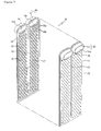
FIGS. 1 to 3 , the one-tank type heat exchanger includes a pair ofparallel tanks 40 placed at the top of the exchanger and havingparallel cups 14 andholes 14a formed in thecups 14,tubes 10 each formed by welding two single ordouble head plates 11 having a predetermined length ofseparators 13 extended from between the pair oftanks 40 to define a generallyU-shaped channels 12 in which thetanks 40 are coupled together at both sides of the eachtube 10, heat radiation fins 50 laminated between thetubes 10 and twoend plates 30 provided at the outermost sides of thetubes 10 and heat radiation fins 50 to reinforce the same. - In each
tube 10, both plates are embossed to have a number of inward-projectedfirst beads 15 so that a turbulent flow is formed in refrigerant flowing through thechannel 12. - Further, in the each
tube 10, thechannel 12 hasrefrigerant distributing sections 16 in inlet and outlet sides thereof, in which eachrefrigerant distributing section 16 has a plurality ofpaths 16b partitioned by at least onesecond beads 16a so that refrigerant is uniformly distributed into thechannel 12. In addition, since the double head plate is substantially same as thesingle head plate 11 except that one or two cups are provided in the bottom end of the double head plate, hereinafter only thesingle head plate 11 having twocups 14 formed in the top end will be illustrated for the sake of convenience. - The
tubes 10 also includemanifold tubes 20 projected into thetanks 40 to communicate with the inside of thetanks 40, in which one of themanifold tubes 20 has aninlet manifold 21 connected to aninlet pipe 2 for introducing refrigerant and the other one of themanifold tubes 20 has anoutlet manifold 21 connected with an outlet pipe 3 for discharging refrigerant. - The
tanks 40 having the inlet andoutlet manifolds 21 are provided with partition means 60 for separating inflow refrigerant from outflow refrigerant in the refrigerant flow within theevaporator 1 as shown inFIG. 1 . - As a consequence, the
tanks 40 are classified into "A" part, "B" part for receiving refrigerant U-turned from the A part, "C" part communicating with the B part for receiving refrigerant, and "D" part for receiving refrigerant U-turned from the C part and then discharging the same to the outside. - When being introduced through the
inlet side manifold 21, refrigerant is uniformly distributed in the A part of thetank 40 and flows through the U-shapedchannels 12. In succession, refrigerant is introduced into the B part of anadjacent tank 40, and then flows into the C part of thesame tank 40 through the U-shapedchannels 12 of thetubes tank 40 having theoutlet side manifold 21 to be discharged to the outside. - Through the heat exchange with the air blown between the
tubes evaporator 1 as above evaporates refrigerant circulating along refrigerant lines of a cooling system while sucking and discharging the same so as to cool the air blown indoors via evaporation latent heat. - However, as shown in
FIG. 3 , thefirst beads 15 in theplates 11 are formed circularly so that stagnation points occur in the inflow direction of thefirst beads 15 when refrigerant is introduced and large pressure is applied to the stagnation points, thereby increasing the pressure drop of refrigerant. Also, refrigerant flowing through thechannel 12 is crowded in the periphery having ununiform flow distribution. - Regarding that the
evaporator 1 is being gradually miniaturized into a compact size, when the pressure drop of refrigerant is increased to impart ununiform flow distribution to refrigerant, theevaporator 1 is to have overcooled/overheated sections. In the overcooled section, a problem of icing may occur in the surface of the evaporator. - In the overheated section, the temperature variation of air degrades the performance of the air conditioning system thereby causing unstableness to the air conditioning system. This also increases the temperature distribution variation of the air passing through the evaporator thereby to degrade the cooling performance.
- The document
EP- discloses a tube element for a laminated heat exchanger wherein the bead width A, the bead spacing B of the beads formed in the tube element, the tube element thickness H and the formed plate thickness T are determined to fall within the range of 2.0 mm ≤ A ≤ 3.0 mm; 3.5 mm ≤ B ≤ 6.3 mm; 1.9 mm ≤ H ≤ 2.7 mm, and 0.25 mm ≤ T ≤ 0.47 mm, respectively. By setting these ranges, it is possible to provide an ideal tube element with which the passage resistance, heat exchanging efficiency, strength and the like are in the best possible balance. A plurality of bead rows which run at a right angle to the direction in which the heat exchanging medium passage is formed are provided in the tube element and the beads may be provided in such a manner that they are located at different intervals in adjacent bead rows or so that the areas where beads are not provided are different among bead rows and these areas may form a continuum. With such a structure, the number of beads provided in the dead water regions is reduced and the passage resistance is reduced so that the flow of the heat exchanging medium is improved.A 0 650 024 - The present invention has been made to solve the foregoing problems and it is therefore an object of the present invention to provide a heat exchange which has streamline first beads for imparting turbulence to refrigerant flowing through channels of plates and second beads in refrigerant distributing sections for forming guide beads extended to first rows of the first beads in order to decrease the pressure drop of refrigerant and improve the flow distribution of refrigerant into uniform state, thereby preventing overcooling/overheating as well as stabilizing an air conditioning system and improving the cooling performance thereof.
- According to an aspect of the invention for realizing the above objects, there is provided a heat exchanger tube formed by welding two plates, said heat exchanger comprising
- a cup forming a tank communicating with a channel;
- a number of first beads projected inward and so arrayed in each plate that opposed sides of the first beads are coupled to each other to impart turbulence to refrigerant flowing through the channel;
- refrigerant distributing sections provided in inlet and outlet sides of the channel; and
- a plurality of second beads extending from the cup toward the channel and projected inward and coupled to each other to divide each of the refrigerant distributing sections into a plurality of paths;
characterized in that - at least one of the second beads is extended longer than the the other second beads and extended further towards an adjacent row of the first beads than the other second beads and is a guide bead, wherein the first beads in the adjacent row are aligned in a first direction, and wherein a perpendicular distance between the guide bead and the line of the adjacent row of the first beads is shorter than a perpendicular distance between the other second beads and the line of the adjacent row of the first beads so that refrigerant flowing through the refrigerant distributing section is uniformly distributed into the channel.
-
-
FIG. 1 is a perspective view schematically illustrating a conventional evaporator; -
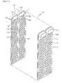
FIG. 2 is an exploded perspective view illustrating plates of conventional tubes; -
FIG. 3 is a schematic view illustrating the flow distribution of refrigerant in conventional plates; -
FIG. 4 is an exploded perspective view illustrating plates of tubes of a heat exchanger not covered by the present invention; -
FIG. 5 illustrates a top portion of a plate of a heat exchanger not covered by the present invention; -
FIG. 6 compares the flow distribution of refrigerant by streamline beads of the plates of a heat exchanger not covered by the present invention with that by conventional circular beads; -
FIG. 7 illustrates graphs comparing flow rate distribution by the streamline beads of the plates of a heat exchanger not covered by the present invention with that by conventional circular beads inFIG. 6 ; -
FIG. 8 is a graph illustrating the heat radiation performance about the width to length ratio of a first bead of a heat exchanger not covered by the present invention; -
FIG. 9 is a graph illustrating the pressure drop about the width to length ratio of the first bead of a heat exchanger not covered by the present invention; -
FIG. 10 illustrates a modification to an array of the first bead in a plate of a heat exchanger not covered by the present invention; -
FIG. 11 is a graph illustrating amount of heat radiation and pressure drop according to the spacing between first beads of a heat exchanger not covered by the present invention; -
FIG. 12 is a graph illustrating heat radiation and pressure drop according to the shape of first beads with respect to the amount of refrigerant flowing through a plate channel of a heat exchanger not covered by the present invention; -
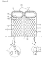
FIG. 13 illustrates a top portion of a plate according to an embodiment of the invention; -
FIG. 14 are views comparing the flow distribution of refrigerant of a refrigerant distributing section having guide beads formed in the plate according to the above embodiment of the invention with that by conventional neck beads; -
FIG. 15 illustrates asymmetric refrigerant distributing section in the plate according to the above embodiment of the invention; -
FIG. 16 illustrates a top portion of a plate according to another embodiment of the invention; -
FIG. 17 illustrates the flow distribution of refrigerant in the plate inFIG. 16 ; -
FIG. 18 illustrates a modification to a refrigerant distributing section in the plate according to another embodiment of the invention; -
FIG. 19 illustrates the flow distribution of refrigerant for the plate inFIG. 18 ; -
FIG. 20 illustrates a modification to an array of first bead in the plate according to another embodiment of the invention; and -
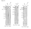
FIG. 21 illustrates one embodiment, which the plate of invention is applied to evaporator plate having one-, two- or four-tanks type. - Hereinafter preferred embodiments of the invention will be described with reference to the accompanying drawings.
- The same reference numerals are used to designate the same or similar components as those of the prior art without repeated description thereof.
-
FIG. 4 is an exploded perspective view illustrating plates of tubes of a heat exchanger not covered by the present invention;FIG. 5 illustrates a top portion of a plate of a heat exchanger not covered by the present invention;FIG. 6 compares the flow distribution of refrigerant by streamline beads of the plates of a heat exchanger not covered by the present invention with that by conventional circular beads;FIG. 7 are graphs comparing flow rate distribution by the streamline beads of the plates with that by conventional circular beads inFIG. 6 ;FIG. 8 is a graph illustrating the heat radiation performance about the width to length ratio of a first bead of a heat exchanger not covered by the present invention;FIG. 9 is a graph illustrating the pressure drop about the width to length ratio of the first bead of a heat exchanger not covered by the present invention;FIG. 10 illustrates a modification to an array of the first bead in a plate of a heat exchanger not covered by the present invention;FIG. 11 is a graph illustrating amount of heat radiation and pressure drop according to the spacing between first beads of a heat exchanger not covered by the present invention; andFIG. 12 is a graph illustrating heat radiation and pressure drop according to the shape of first beads with respect to the amount of refrigerant flowing through a plate channel of a heat exchanger not covered by the present invention. - While it is apparent that the present invention shall be applied equally to one-, two-and four-
tank type evaporators 1, the following description will be made only in conjunction with the singletank type evaporator 1 for the sake of convenience. - As is known from background art, the
evaporator 1 includes a pair ofparallel tanks 118 placed at the top of a heat exchanger and havingparallel cups 114,tubes 110 each formed by welding twoplates 111 having a predetermined length ofseparators 113 extended from between the pair oftanks 118 to define a generallyU-shaped channels 112 in which thetanks 118 are coupled together at both sides of the eachtube 110, heat radiation fins 50 (of the prior art) laminated between thetubes 110 and two end plates 30 (of the prior art) provided at the outermost sides of thetubes 110 and the heat radiation fins 50 (of the prior art) to reinforce the same. - The
tubes 110 also include manifold tubes 20 (of the prior art) each formed by welding a pair of manifold plates which are projected into thetanks 118 to communicate with the inside of thetanks 118 and have manifolds 21 (of the prior art) coupled with inlet andoutlet pipes 2 and 3. In thetubes 110 and 20 (of the prior art), eachchannel 112 has refrigerant distributingsections 116 in inlet and outlet sides thereof, in which each refrigerant distributingsection 116 has a plurality ofpaths 116b partitioned by at least onesecond bead 116a so that refrigerant is uniformly distributed into thechannel 112. - Also in each
plate 111, a number offirst beads 115 are projected inward via embossing along thechannel 112 at both sides about theseparator 113 so that a turbulent flow is formed in refrigerant flowing through thechannel 112. Thefirst beads 115 are arrayed regularly and diagonally into the form of a lattice to improve the fluidity of refrigerant while creating a turbulent flow. Theseparators 113 and thefirst beads 115 in the twoplates 111 are in contact with each other and then coupled together via brazing. - In the
prior art evaporator 1 as described above, thefirst beads 115 are preferably streamlined. - This reason will be described hereinafter with reference to the drawing comparing the flow distribution of refrigerant by the circular beads 15 (of the prior art) with that by the streamline
first beads 115 as shown inFIG. 6 . - In the first circular beads 15 (of the prior art) as described, stagnation points are formed in inlet side regions of the first beads 15 (of the prior art), and large pressure is applied to the stagnation points increasing the magnitude of pressure drop in refrigerant. Thus, it is observed that refrigerant is crowded in the periphery creating an ununiform flow in the
channel 12. However, thefirst beads 115 of the prior art heat exchanger are streamlined to decrease the magnitude of pressure drop thereby preventing any large pressure at stagnation points in inlet side regions of thefirst beads 115. As a result, it is observed that refrigerant smoothly flows along the streamline surface of thefirst beads 115. - In graphs in
FIG. 7 comparing the flow rate distribution by the first circular beads 15 (of the prior art) with that by the streamlinefirst beads 115 of the the prior art heat exchanger, X-axis indicates the inside range of the plates, and Y axis indicates the flow rate. - It is observed from the graph related with the first circular beads 15 (of the prior art) that refrigerant flows fast at both sides of the plate but slowly in the center thereby to cause a large difference in the flow rate.
- However, the graph related with the
first beads 115 of the other prior art heat exchanger shows uniform flow rate distribution across the entire ranges. - Regarding the above results, it is apparent that the streamline
first beads 115 are positively improved in not only the flow distribution of refrigerant but also the flow rate distribution of refrigerant over that of circular first beads 15 (of the prior art). - Also in the streamline
first beads 115, since backwash occurs in the rear part owing to counter stream while refrigerant passes through thebeads 115, the contact area to be contacted by refrigerant is increased to improve heat conduction performance while the backwash is relatively decreased in quantity to remove the dead zone by the backwash in the circular beads 15 (of the prior art). - Herein the backwash occurring during the passage of refrigerant through the
first beads 115 promotes turbulence to refrigerant thereby improving heat conduction performance. - However, the heavy backwash by the conventional
circular beads 15 may create the dead zone and impart non-uniformity to the flow of refrigerant owing to pressure difference thereby causing the probability of overcooling/overheating. Also, the backwash if too much insignificant may lower the promotion of turbulence or heat conduction. - Accordingly, the
first beads 115 of the other conventional heat exchanger are streamlined to reduce the pressure at leading ends in the inflow direction of refrigerant, regulate the backwash to a proper level, improve the non-uniformity of the flow distribution of refrigerant and raise the heat conduction performance, in which the ratio W/L of the width W to the length L of eachfirst bead 115 is limited as seen from graphs inFIGS. 8 and 9 . - If the width to length ratio W/L of the
first bead 115 decreases, the magnitude of pressure drop in refrigerant advantageously reduces but the heat radiation performance is degraded (for about 2 to 3 %). - If the width to length ratio W/L increases, the heat radiation performance advantageously increases more or less, but the magnitude of pressure drop of refrigerant increases thereby to impart non-uniformity to the flow distribution of refrigerant. Therefore, the
first bead 115 of the other conventional heat exchanger is designed to have the width to length ratio W/L satisfying an equation of 0.35 ≤ W/L ≤ 0.75. More preferably, the width to length ratio of thefirst bead 115 satisfies an equation of 0.4 ≤ W/L ≤ 0.6 in view of productivity and performance. It is also preferable that the width W of thefirst bead 115 is 1 mm or more. - If the width W of the
first bead 115 is smaller than 1 mm, cracks may occur in theplates 111 in the manufacture thereby causing difficulty to the manufacture. Also, the reduction in the width W relatively increases the length L so that the interference betweenadjacent beads 115 may cause cracks. - In the meantime, as shown in
FIG. 10 , thefirst beads 115 arrayed in thechannel 112 may be modified to have rows ofcircular beads 115a between respective rows of thestreamline beads 115 so that thecircular bead 115a rows alternate with thestreamline bead rows 115. - The
first beads channel 112 preferably satisfy an equation 0.3 mm ≤ S ≤ 5.0 mm, wherein S indicates the spacing between two longitudinally adjacent rows of thebeads - If the spacing S between the adjacent rows of the
beads FIG. 11 . Also, when thefirst beads - If the spacing S between the adjacent rows of the
beads - Therefore, it is preferably determined that the spacing S between the adjacent rows of the
beads - In addition, where the spacing between the longitudinally adjacent rows of the
beads first bead first bead bead equation 20 ° ≤ α ≤ 70 °. - That is, if α is under 20 °, the vertical distance between the
first beads - If α exceeds 70 °, the vertical distance between the
first beads -
FIG. 12 is a graph illustrating the heat radiation and the pressure drop varying according to the amount of refrigerant flowing through the channel in order to compare the heat radiation and the pressure drop with respect to an array of circular first beads, an array of alternating circular and streamline first beads and array of streamline beads. - As seen in
FIG. 12 , the streamlinefirst beads 115 achieve the highest heat radiation but the lowest pressure drop thereby showing improvement in the flow distribution of refrigerant. - In addition, it is apparent that the
streamline beads 115 are more advantageous than the circular beads at a low flow rate. -
FIG. 13 illustrates a top portion of a plate according to an embodiment of the invention;FIG. 14 are views comparing the flow distribution of refrigerant of a refrigerant distributing section having guide beads formed in the plate according to the above embodiment of the invention with that by conventional neck beads; andFIG. 15 illustrates asymmetric refrigerant distributing sections in the plate according to the above embodiment of the invention, in which the components same as those of the above conventional heat exchanger will not be repeatedly described. - As shown in
FIGS. 13 to 15 , insecond beads 116a formed in arefrigerant distributing section 116, guidebeads 117 are extended to a predetermined length longer than othersecond beads 116a so that refrigerant flowing through refrigerant distributingsections 116 can be uniformly distributed toward achannel 112. - The
guide bead 117 is preferably formed streamlined and thus taper in width toward an end. - Preferably, a central one of the
guide beads 117 is formed longer than other ones of theguide beads 117. - In the meantime,
first beads 115a in thechannel 112 are formed circular. - Instead of being circularly shaped, the
first beads 115a may be formed streamlined as in the above conventional heat exchanger, which will be described again later in the specification. Further, thefirst beads 115a have the spacing S between longitudinallyadjacent beads 115a in the range of 0.3 to 5. 0 mm.FIG. 14 compares the flow distribution of refrigerant by a conventional refrigerant distributing section with that of the refrigerant distributing section having the guide beads. - As seen in
FIG. 14 , although it is required that refrigerant introduced from atank 118 should be uniformly distributed toward thechannel 112 after flowing through therefrigerant distributing section 116, the conventional refrigerant distributing section 16 (of the prior art) fails to uniformly distribute refrigerant so that refrigerant is crowded in the periphery. - On the contrary, it is observed in the
refrigerant distributing section 116 having theguide beads 117 that refrigerant flowing through therefrigerant distributing section 116 is guided by theguide beads 117 to be uniformly distributed to thefirst beads 115a arrayed in thechannel 112. - As a result, the
guide beads 117 extended to the predetermined length can improve the flow distribution of refrigerant to prevent overcooling/overheating. - While it is possible to provide a pair of refrigerant distributing
sections 116 having theguide beads 117 symmetrically in inlet and outlet sides of thechannel 112, they may be provided asymmetrically as inFIG. 15 . That is, theguide beads 117 may be formed only in the inlet side refrigerant distributingsection 116 of thechannel 112. -
FIG. 16 illustrates a top portion of a plate according to another embodiment of the invention;FIG. 17 illustrates the flow distribution of refrigerant in the plate inFIG. 16 ;FIG. 18 illustrates a modification to a refrigerant distributing section in the plate according to the other embodiment of the invention;FIG. 19 illustrates the flow distribution of refrigerant for the plate inFIG. 18 ; andFIG. 20 illustrates a modification to an array of first bead in the plate according to the other embodiment of the invention, in which the components same as those of the conventional heat exchanger and embodiments of the invention will not be repeatedly described. - As shown in
FIGS. 16 to 20 , the further embodiment has streamlinefirst beads 115 and guidebeads 117a amongsecond beads 116a of refrigerant distributingsections 116. - That is, this embodiment embraces all effects obtainable from the streamline
first beads 115 of the conventional heat exchanger and from theguide beads 117 formed in thesecond beads 116a of the refrigerant distributingsections 116 of the above embodiment of the invention in order to achieve the maximum performance. - Preferably, the width W to length L ratio W/L of a
first bead 115 satisfies a suitable range defined by an equation of 0.35 ≤ W/L ≤ 0.75 as in the above embodiment, and the spacing S between longitudinallyadjacent beads 115 satisfies an equation 0.3 mm ≤ S ≤ 5.0 mm. - Also, a
guide bead 117a in the center ofsecond beads 116a formed in therefrigerant distributing section 116 is extended to a first row of thefirst beads 115. - Preferably, one of the
first beads 115 in the first row corresponding to theguide bead 117a is removed. - In the meantime, as shown in
FIG. 18 , not only the central ones of thesecond beads 116a of the refrigerant distributingsection 116 but also both ones thereof may be formed intoguide beads 117a extending to the first row of thefirst beads 115. Furthermore, modifications may be made more variously other than those shown in the drawings. - Therefore, referring to the analyses of the refrigerant flow distribution shown in
FIGS. 17 and19 , when flowing throughpaths 116b of the refrigerant distributingsections 116, refrigerant is introduced by theguide beads 117a and flows toward thefirst beads 115 to prevent dead zones between thesecond beads 116a and the first row of thefirst beads 115. This also uniformly distributes refrigerant to prevent the crowding of refrigerant in both lateral portions and overcooling/overheating. In the meantime, as shown inFIG. 20 , a number offirst beads channel 112 are modified so thatstreamline bead 115 rows alternate withcircular bead rows 115a.FIG. 21 illustrates one embodiment, which the plate of invention is applied to evaporator plate having one-, two-or four-tanks type. - As show in
FIG. 21 , the one-tank type evaporator plate will not be described since it was described above. - In the two-tank type evaporator plate,
tanks 118 are provided in the top and bottom of thetube 110, respectively, and achannel 112 linearly connects thetanks 118. In refrigerant distributingsections 116 formed in inlet and outlet sides of thechannel 112, central ones ofsecond beads 116a are longitudinally extended to formguide beads 117a, respectively. - In the four-tank type evaporator plate, a first pair of
parallel tanks 118 is provided at the top of a tube, and a second pair ofparallel tanks 118 is provided in the bottom of the tube. - Two
channels 112 are formed divided by aseparator 113 that is vertically extended between the first and second pairs oftanks 118. In refrigerant distributingsections 116 provided in inlet and outlet sides of eachchannel 112,second beads 116a are extended to a predetermined length to formguide beads 117. Meanwhile, all thefirst beads 115 in the one-, two-and four-tank type plates 111 are formed streamlined; but they might be formed circular. - According to the heat exchanger plate of the invention as set forth above, the
first beads 115 in theplate 111 are formed streamlined and thesecond beads 116a in the refrigerant distributingsections 116 form theguide beads first beads 115 so that refrigerant flowing through thepaths 116b in the refrigerant distributingsections 116 is introduced by theguide beads first beads 115 arrayed in thechannel 112. This structure also reduces the pressure drop but increases the heat radiation to improve the heat exchange performance thereby to facilitate the miniaturization of theevaporator 1. - While the present invention has been described in conjunction with the
plate 111 of thetube 110 adopted in theevaporator 1 in which thefirst beads 115 are formed streamlined and thesecond beads 116a of the refrigerant distributingsections 116 form theguide beads first beads 115 and thesecond beads 116a may be modified into various forms without departing from the scope of the invention as defined by the appended claims. Also, the same structure may be applied to the two-or four-tank type evaporator 1 obtaining the same effect as that of the invention. - According to the invention as described hereinbefore, the streamline first beads are formed to impart turbulence to refrigerant flowing through the channels of the plates while the second beads in the refrigerant distributing sections form the guide beads extended to the first rows of the first beads in order to decrease the pressure drop of refrigerant but increasing the heat radiation thereof thereby improving the heat exchange efficiency.
- Furthermore, both the flow distribution of refrigerant and the temperature distribution of passed air are uniformly improved to prevent the evaporator from overcooling/overheating as well as stabilize an air conditioning system while improving its performance.
- Moreover, the pressure drops of refrigerant decreases to facilitate the miniaturization of the evaporator into a compact size. While the present invention has been described with reference to the particular illustrative embodiments, it is not to be restricted by the embodiments but only by the appended claims. It is to be appreciated that those skilled in the art can change or modify the embodiments without departing from the scope of the present invention as defined by the claims.
Claims (11)
- A heat exchanger tube (110) formed by welding two plates, comprising- a cup forming a tank (118) communicating with a channel (112);- a number of first beads (115, 115a) projected inward and so arrayed in each plate that opposed sides of the first beads (115, 115a) are coupled to each other to impart turbulence to refrigerant flowing through the channel (112);- refrigerant distributing sections (116) provided in inlet and outlet sides of the channel (112); and- a plurality of second beads (116a) extending from the cup toward the channel (112) and projected inward and coupled to each other to divide each of the refrigerant distributing sections (116) into a plurality of paths (116b); characterized in that- at least one of the second beads (116a) is extended longer than the other second beads (116a) and extended further towards an adjacent row of the first beads (115, 115a) than the other second beads (116a) and is a guide bead (117, 117a), wherein the first beads (115, 115a) in the adjacent row are aligned in a first direction and wherein a perpendicular distance between the guide bead (117, 117a) and the line of the adjacent row of the first beads (115, 115a) is shorter than a perpendicular distance between the other second beads (116a) and the line of the adjacent row of the first beads (115, 115a) so that refrigerant flowing through the refrigerant distributing section (116) is uniformly distributed into the channel (112).
- The heat exchanger tube according to claim 1, wherein the guide bead (117, 117a) is formed streamlined and tapers in width toward an end.
- The heat exchanger tube according to claim 2, wherein the refrigerant distributing sections (116) provided in the inlet and outlet sides of the channel (112) are symmetric with each other.
- The heat exchanger tube according to claim 2, wherein the refrigerant distributing sections (116) provided in the inlet and outlet sides of the channel (112) are asymmetric with each other.
- The heat exchanger tube according to claim 1, wherein the guide bead (117,117a) is extended to a first row of the first beads (115).
- The heat exchanger tube according to claim 1, wherein the first beads (115) are formed streamlined and satisfy an equation of 0.35 ≤ W/L ≤ 0.75, wherein W is the width and L is the length.
- The heat exchanger tube according to claim 6, wherein the first beads (115, 115a) have a spacing S between longitudinally adjacent ones of the beads (115, 115a), and the spacing S satisfies an equation of 0.3 mm ≤ S ≤ 5.0 mm.
- The heat exchanger tube according to claim 7, wherein a center line C1 of one row of the first bead (115, 115a) intersects with a line C2 connecting the center of a first bead (115, 115a) in the other row at the shortest distance from the center of one bead (115, 115a) on the center line C1 at an angle α satisfying an equation 20 ° ≤ α ≤ 70 °.
- The heat exchanger tube according to claim 1, wherein a pair of parallel tanks (118) are provided at a top of the tube (110), the channel (112) forms a U-shaped channel (112) by a separator (113) extended from between the pair of tanks (118) to vertically partition a predetermined portion.
- The heat exchanger tube according to claim 1, wherein tanks (118) are provided at a top and a bottom of the tube (110), respectively.
- The heat exchanger tube according to claim 1, wherein two pairs of parallel tanks (118) are provided at a top and a bottom of the tube (110), respectively, and the channel (112) is partitioned into two separate channels (112) by a separator (113) vertically formed between the pairs of tanks (118).
Applications Claiming Priority (2)
| Application Number | Priority Date | Filing Date | Title |
|---|---|---|---|
| KR1020030034339A KR100950714B1 (en) | 2003-05-29 | 2003-05-29 | Plate for heat exchanger |
| PCT/KR2004/001258 WO2004106835A2 (en) | 2003-05-29 | 2004-05-28 | Plate for heat exchanger |
Publications (3)
| Publication Number | Publication Date |
|---|---|
| EP1644683A2 EP1644683A2 (en) | 2006-04-12 |
| EP1644683A4 EP1644683A4 (en) | 2010-07-21 |
| EP1644683B1 true EP1644683B1 (en) | 2013-11-20 |
Family
ID=36819223
Family Applications (1)
| Application Number | Title | Priority Date | Filing Date |
|---|---|---|---|
| EP04773831.5A Expired - Lifetime EP1644683B1 (en) | 2003-05-29 | 2004-05-28 | Heat exchanger tube |
Country Status (6)
| Country | Link |
|---|---|
| US (1) | US7934541B2 (en) |
| EP (1) | EP1644683B1 (en) |
| JP (1) | JP4211998B2 (en) |
| KR (1) | KR100950714B1 (en) |
| CN (1) | CN100458354C (en) |
| WO (1) | WO2004106835A2 (en) |
Families Citing this family (29)
| Publication number | Priority date | Publication date | Assignee | Title |
|---|---|---|---|---|
| KR101104278B1 (en) * | 2005-03-30 | 2012-01-12 | 한라공조주식회사 | Plate for heat exchanger |
| DE102005044558A1 (en) * | 2005-09-17 | 2007-03-29 | Behr Gmbh & Co. Kg | Heat exchanger, in particular radiator, for air conditioning |
| US7413003B2 (en) | 2006-09-15 | 2008-08-19 | Halla Climate Control Corporation | Plate for heat exchanger |
| FR2906020B1 (en) * | 2006-09-15 | 2008-11-14 | Halla Climate Control Corp | PLATE FOR A HEAT EXCHANGER. |
| SE530970C2 (en) * | 2007-03-07 | 2008-11-04 | Airec Ab | Cross current type heat exchanger |
| DE202012102349U1 (en) * | 2011-07-14 | 2012-07-18 | Visteon Global Technologies, Inc. | battery cooler |
| EP3767219A1 (en) | 2011-10-19 | 2021-01-20 | Carrier Corporation | Flattened tube finned heat exchanger and fabrication method |
| DE102012006346B4 (en) * | 2012-03-28 | 2014-09-18 | Modine Manufacturing Co. | heat exchangers |
| US10690421B2 (en) | 2012-03-28 | 2020-06-23 | Modine Manufacturing Company | Heat exchanger and method of cooling a flow of heated air |
| DE102012217333A1 (en) * | 2012-09-25 | 2014-03-27 | Behr Gmbh & Co. Kg | flat tube |
| DE102013216523B4 (en) * | 2013-08-21 | 2026-01-22 | Mahle International Gmbh | Plate heat exchanger |
| CN103743281B (en) * | 2014-01-16 | 2015-10-28 | 深圳市丰瑞德机电技术有限公司 | A kind of heat exchanger plates, heat exchanger and heat-exchange system |
| WO2016023393A1 (en) | 2014-08-12 | 2016-02-18 | 丹佛斯微通道换热器(嘉兴)有限公司 | Heat exchange plate and plate-type heat exchanger |
| EP3270085B1 (en) * | 2016-07-12 | 2019-11-06 | Borgwarner Emissions Systems Spain, S.L.U. | Heat exchanger for an egr system |
| JP2018013262A (en) * | 2016-07-19 | 2018-01-25 | カルソニックカンセイ株式会社 | Heat exchanger |
| CN107664445A (en) * | 2016-07-28 | 2018-02-06 | 恒丰工程(香港)有限公司 | Multi-flow detachable plate heat exchanger and special heat exchange plate thereof |
| US10006643B1 (en) | 2017-04-14 | 2018-06-26 | Scandic Builders, Inc. | Technologies for underfloor fluid conduction |
| CN107687780B (en) * | 2017-08-05 | 2019-06-18 | 中国科学院工程热物理研究所 | Heat exchange plate with streamlined rib structure and printed circuit board heat exchanger comprising the same |
| DE102017223616A1 (en) * | 2017-12-21 | 2019-06-27 | Mahle International Gmbh | Flat tube for an exhaust gas cooler |
| CN108386919A (en) * | 2018-05-07 | 2018-08-10 | 廊坊市秀达节能设备工程有限公司 | A kind of ultrathin type infiltration type air conditioner |
| CN108666704A (en) * | 2018-06-29 | 2018-10-16 | 威马智慧出行科技(上海)有限公司 | A kind of heat-exchanger rig |
| EP3598046B1 (en) * | 2018-07-20 | 2023-05-17 | Valeo Vyminiky Tepla, s.r.o. | Heat exchanger plate and heat exchanger comprising such a heat exchanger plate |
| FR3086378B1 (en) * | 2018-09-25 | 2021-01-22 | Valeo Systemes Thermiques | PLATE CONSTITUTING A HEAT EXCHANGER AND HEAT EXCHANGER INCLUDING AT LEAST ONE SUCH PLATE |
| CN111351376A (en) * | 2018-12-21 | 2020-06-30 | 浙江盾安热工科技有限公司 | Heat exchanger flat tube and heat exchanger with same |
| CN111366013A (en) * | 2018-12-26 | 2020-07-03 | 浙江盾安热工科技有限公司 | Flat pipe and heat exchanger |
| DE102019201387A1 (en) * | 2019-02-04 | 2020-08-06 | Mahle International Gmbh | Stacking disc for a stacked disc heat exchanger and associated stacked disc heat exchanger |
| KR102676721B1 (en) * | 2019-04-24 | 2024-06-18 | 현대자동차주식회사 | Cooling system for power conversion device |
| CN111912280A (en) * | 2019-05-09 | 2020-11-10 | 浙江盾安热工科技有限公司 | Flat pipe, heat exchanger and heat pump water heater |
| DE102020212900A1 (en) * | 2020-02-04 | 2021-08-05 | Hanon Systems | Dimple cooler with additional dimples |
Family Cites Families (32)
| Publication number | Priority date | Publication date | Assignee | Title |
|---|---|---|---|---|
| FR813272A (en) * | 1936-11-12 | 1937-05-29 | Anciens Etablissements Lamblin | Cooling radiators for engines or other applications |
| US4600053A (en) * | 1984-11-23 | 1986-07-15 | Ford Motor Company | Heat exchanger structure |
| DE3622316C1 (en) * | 1986-07-03 | 1988-01-28 | Schmidt W Gmbh Co Kg | Plate heat exchanger |
| JPH01244282A (en) * | 1988-03-25 | 1989-09-28 | Nippon Denso Co Ltd | Laminate-type heat exchanger |
| US5062477A (en) * | 1991-03-29 | 1991-11-05 | General Motors Corporation | High efficiency heat exchanger with divider rib leak paths |
| US5101891A (en) * | 1991-06-03 | 1992-04-07 | General Motors Corporation | Heat exchanger tubing with improved fluid flow distribution |
| US5111878A (en) * | 1991-07-01 | 1992-05-12 | General Motors Corporation | U-flow heat exchanger tubing with improved fluid flow distribution |
| US5125453A (en) * | 1991-12-23 | 1992-06-30 | Ford Motor Company | Heat exchanger structure |
| US5409056A (en) * | 1992-05-11 | 1995-04-25 | General Motors Corporation | U-flow tubing for evaporators with bump arrangement for optimized forced convection heat exchange |
| JPH0666487A (en) * | 1992-08-13 | 1994-03-08 | Showa Alum Corp | Laminated type heat exchanger |
| KR200145266Y1 (en) | 1993-07-30 | 1999-06-15 | 신영주 | Heat exchanging device |
| DE69413173T2 (en) | 1993-10-22 | 1999-06-02 | Zexel Corp | Pipe element for a laminate heat exchanger |
| JPH07167581A (en) * | 1993-10-22 | 1995-07-04 | Zexel Corp | Tube elements of lamination type heat exchanger |
| JPH08136179A (en) * | 1994-11-04 | 1996-05-31 | Zexel Corp | Laminated type heat exchanger |
| JP3172859B2 (en) * | 1995-02-16 | 2001-06-04 | 株式会社ゼクセルヴァレオクライメートコントロール | Stacked heat exchanger |
| US5979544A (en) * | 1996-10-03 | 1999-11-09 | Zexel Corporation | Laminated heat exchanger |
| CN1204044A (en) * | 1997-05-30 | 1999-01-06 | 三星电子株式会社 | heat exchanger |
| JP4122578B2 (en) * | 1997-07-17 | 2008-07-23 | 株式会社デンソー | Heat exchanger |
| JP2941768B1 (en) * | 1998-03-16 | 1999-08-30 | 株式会社日本クライメイトシステムズ | Stacked heat exchanger |
| KR100528997B1 (en) * | 1998-04-23 | 2006-02-09 | 한라공조주식회사 | Multilayer Heat Exchanger |
| JP2000193392A (en) * | 1998-12-25 | 2000-07-14 | Zexel Corp | Laminated heat exchanger |
| FR2788123B1 (en) * | 1998-12-30 | 2001-05-18 | Valeo Climatisation | EVAPORATOR, HEATING AND/OR AIR CONDITIONING DEVICE AND VEHICLE COMPRISING SUCH EVAPORATOR |
| US6401804B1 (en) * | 1999-01-14 | 2002-06-11 | Denso Corporation | Heat exchanger only using plural plates |
| JP4018279B2 (en) | 1999-01-19 | 2007-12-05 | カルソニックカンセイ株式会社 | Flat tube for heat exchanger |
| JP4175443B2 (en) * | 1999-05-31 | 2008-11-05 | 三菱重工業株式会社 | Heat exchanger |
| GB2351800B (en) * | 1999-06-29 | 2001-07-25 | Calsonic Kansei Corp | Evaporator of automotive air-conditioner |
| JP2001041677A (en) * | 1999-08-03 | 2001-02-16 | Mitsubishi Heavy Ind Ltd | Heat exchanger |
| JP2001027491A (en) * | 1999-07-14 | 2001-01-30 | Mitsubishi Heavy Ind Ltd | Heat-exchanger |
| KR100688236B1 (en) | 2000-05-31 | 2007-02-28 | 한라공조주식회사 | Integral heat exchanger |
| JP2002107004A (en) * | 2000-09-27 | 2002-04-10 | Calsonic Kansei Corp | Stacked type evaporator |
| KR100819010B1 (en) * | 2001-08-29 | 2008-04-02 | 한라공조주식회사 | heat transmitter |
| FR2831654B1 (en) * | 2001-10-31 | 2004-02-13 | Valeo Climatisation | THERMAL EXCHANGER TUBES WITH OPTIMIZED PLATES |
-
2003
- 2003-05-29 KR KR1020030034339A patent/KR100950714B1/en not_active Expired - Fee Related
-
2004
- 2004-05-28 WO PCT/KR2004/001258 patent/WO2004106835A2/en not_active Ceased
- 2004-05-28 US US10/558,791 patent/US7934541B2/en not_active Expired - Fee Related
- 2004-05-28 CN CNB2004800149129A patent/CN100458354C/en not_active Expired - Fee Related
- 2004-05-28 JP JP2006508532A patent/JP4211998B2/en not_active Expired - Fee Related
- 2004-05-28 EP EP04773831.5A patent/EP1644683B1/en not_active Expired - Lifetime
Also Published As
| Publication number | Publication date |
|---|---|
| WO2004106835B1 (en) | 2005-09-15 |
| CN100458354C (en) | 2009-02-04 |
| JP2006526130A (en) | 2006-11-16 |
| KR100950714B1 (en) | 2010-03-31 |
| WO2004106835A2 (en) | 2004-12-09 |
| EP1644683A4 (en) | 2010-07-21 |
| JP4211998B2 (en) | 2009-01-21 |
| CN1798951A (en) | 2006-07-05 |
| US20060249281A1 (en) | 2006-11-09 |
| KR20040102747A (en) | 2004-12-08 |
| EP1644683A2 (en) | 2006-04-12 |
| US7934541B2 (en) | 2011-05-03 |
| WO2004106835A3 (en) | 2005-05-26 |
Similar Documents
| Publication | Publication Date | Title |
|---|---|---|
| US7934541B2 (en) | Plate for heat exchanger | |
| EP3760962B1 (en) | Heat exchanger | |
| US9291407B2 (en) | Multi-channel heat exchanger with improved uniformity of refrigerant fluid distribution | |
| EP2410278B1 (en) | Plate-type heat exchanger and refrigerating air-conditioning device | |
| US6863120B2 (en) | Laminated heat exchanger | |
| US7413003B2 (en) | Plate for heat exchanger | |
| US20110139413A1 (en) | Flow distributor for a heat exchanger assembly | |
| JP2010538239A (en) | Evaporator | |
| WO2013191056A1 (en) | Heat exchanger | |
| WO2017126019A1 (en) | Heat exchanger | |
| US7303004B2 (en) | Heat exchanger | |
| JP2001515196A (en) | Turbulent heat exchanger with interrupted rotation for heat exchangers. | |
| CN214666186U (en) | Heat exchanger | |
| CN100533046C (en) | Plate used for heat converter | |
| KR100528997B1 (en) | Multilayer Heat Exchanger | |
| KR100270139B1 (en) | heat transmitter | |
| KR101104278B1 (en) | Plate for heat exchanger | |
| KR20020045042A (en) | Tube for heat exchanger | |
| CN219433895U (en) | Plate type heat exchanger plate and plate type heat exchanger formed by plate type heat exchanger plate | |
| KR101318626B1 (en) | Evaporator | |
| KR101318624B1 (en) | Heat Exchanger | |
| WO2025247381A1 (en) | Fin and heat exchanger | |
| KR20040061170A (en) | Manifold plate for heat exchanger | |
| KR20000002366A (en) | Heat exchanger | |
| KR20040102489A (en) | Plate of Laminated heat exchanger |
Legal Events
| Date | Code | Title | Description |
|---|---|---|---|
| PUAI | Public reference made under article 153(3) epc to a published international application that has entered the european phase |
Free format text: ORIGINAL CODE: 0009012 |
|
| 17P | Request for examination filed |
Effective date: 20051129 |
|
| AK | Designated contracting states |
Kind code of ref document: A2 Designated state(s): DE FR GB IT PT SE |
|
| DAX | Request for extension of the european patent (deleted) | ||
| RBV | Designated contracting states (corrected) |
Designated state(s): DE FR GB IT PT SE |
|
| A4 | Supplementary search report drawn up and despatched |
Effective date: 20100617 |
|
| 17Q | First examination report despatched |
Effective date: 20110526 |
|
| GRAP | Despatch of communication of intention to grant a patent |
Free format text: ORIGINAL CODE: EPIDOSNIGR1 |
|
| INTG | Intention to grant announced |
Effective date: 20130607 |
|
| GRAS | Grant fee paid |
Free format text: ORIGINAL CODE: EPIDOSNIGR3 |
|
| RAP1 | Party data changed (applicant data changed or rights of an application transferred) |
Owner name: HALLA VISTEON CLIMATE CONTROL CORP. |
|
| GRAA | (expected) grant |
Free format text: ORIGINAL CODE: 0009210 |
|
| AK | Designated contracting states |
Kind code of ref document: B1 Designated state(s): DE FR GB IT PT SE |
|
| REG | Reference to a national code |
Ref country code: GB Ref legal event code: FG4D |
|
| REG | Reference to a national code |
Ref country code: DE Ref legal event code: R096 Ref document number: 602004043848 Country of ref document: DE Effective date: 20140116 |
|
| PG25 | Lapsed in a contracting state [announced via postgrant information from national office to epo] |
Ref country code: SE Free format text: LAPSE BECAUSE OF FAILURE TO SUBMIT A TRANSLATION OF THE DESCRIPTION OR TO PAY THE FEE WITHIN THE PRESCRIBED TIME-LIMIT Effective date: 20131120 |
|
| PG25 | Lapsed in a contracting state [announced via postgrant information from national office to epo] |
Ref country code: PT Free format text: LAPSE BECAUSE OF FAILURE TO SUBMIT A TRANSLATION OF THE DESCRIPTION OR TO PAY THE FEE WITHIN THE PRESCRIBED TIME-LIMIT Effective date: 20140320 |
|
| REG | Reference to a national code |
Ref country code: DE Ref legal event code: R097 Ref document number: 602004043848 Country of ref document: DE |
|
| PLBE | No opposition filed within time limit |
Free format text: ORIGINAL CODE: 0009261 |
|
| STAA | Information on the status of an ep patent application or granted ep patent |
Free format text: STATUS: NO OPPOSITION FILED WITHIN TIME LIMIT |
|
| 26N | No opposition filed |
Effective date: 20140821 |
|
| REG | Reference to a national code |
Ref country code: DE Ref legal event code: R097 Ref document number: 602004043848 Country of ref document: DE Effective date: 20140821 |
|
| PG25 | Lapsed in a contracting state [announced via postgrant information from national office to epo] |
Ref country code: IT Free format text: LAPSE BECAUSE OF FAILURE TO SUBMIT A TRANSLATION OF THE DESCRIPTION OR TO PAY THE FEE WITHIN THE PRESCRIBED TIME-LIMIT Effective date: 20131120 |
|
| REG | Reference to a national code |
Ref country code: FR Ref legal event code: PLFP Year of fee payment: 13 |
|
| REG | Reference to a national code |
Ref country code: DE Ref legal event code: R082 Ref document number: 602004043848 Country of ref document: DE Representative=s name: SCHWABE SANDMAIR MARX PATENTANWAELTE RECHTSANW, DE Ref country code: DE Ref legal event code: R082 Ref document number: 602004043848 Country of ref document: DE Representative=s name: SSM SANDMAIR PATENTANWAELTE RECHTSANWALT PARTN, DE |
|
| REG | Reference to a national code |
Ref country code: FR Ref legal event code: PLFP Year of fee payment: 14 |
|
| REG | Reference to a national code |
Ref country code: FR Ref legal event code: PLFP Year of fee payment: 15 |
|
| PGFP | Annual fee paid to national office [announced via postgrant information from national office to epo] |
Ref country code: GB Payment date: 20220425 Year of fee payment: 19 Ref country code: FR Payment date: 20220422 Year of fee payment: 19 Ref country code: DE Payment date: 20220420 Year of fee payment: 19 |
|
| REG | Reference to a national code |
Ref country code: DE Ref legal event code: R119 Ref document number: 602004043848 Country of ref document: DE |
|
| GBPC | Gb: european patent ceased through non-payment of renewal fee |
Effective date: 20230528 |
|
| PG25 | Lapsed in a contracting state [announced via postgrant information from national office to epo] |
Ref country code: DE Free format text: LAPSE BECAUSE OF NON-PAYMENT OF DUE FEES Effective date: 20231201 Ref country code: GB Free format text: LAPSE BECAUSE OF NON-PAYMENT OF DUE FEES Effective date: 20230528 |
|
| PG25 | Lapsed in a contracting state [announced via postgrant information from national office to epo] |
Ref country code: FR Free format text: LAPSE BECAUSE OF NON-PAYMENT OF DUE FEES Effective date: 20230531 |