EP1643680A1 - Method and system for managing network nodes in MPLS-VPN networks - Google Patents
Method and system for managing network nodes in MPLS-VPN networks Download PDFInfo
- Publication number
- EP1643680A1 EP1643680A1 EP05018947A EP05018947A EP1643680A1 EP 1643680 A1 EP1643680 A1 EP 1643680A1 EP 05018947 A EP05018947 A EP 05018947A EP 05018947 A EP05018947 A EP 05018947A EP 1643680 A1 EP1643680 A1 EP 1643680A1
- Authority
- EP
- European Patent Office
- Prior art keywords
- vpn
- network
- nodes
- status
- vrf
- Prior art date
- Legal status (The legal status is an assumption and is not a legal conclusion. Google has not performed a legal analysis and makes no representation as to the accuracy of the status listed.)
- Granted
Links
- 238000000034 method Methods 0.000 title claims abstract description 24
- 238000004590 computer program Methods 0.000 claims 1
- 230000008676 import Effects 0.000 description 8
- 230000008569 process Effects 0.000 description 5
- 230000000875 corresponding effect Effects 0.000 description 3
- 230000008901 benefit Effects 0.000 description 2
- 230000008439 repair process Effects 0.000 description 2
- 238000007792 addition Methods 0.000 description 1
- 238000004891 communication Methods 0.000 description 1
- 230000002596 correlated effect Effects 0.000 description 1
- 230000037430 deletion Effects 0.000 description 1
- 238000012217 deletion Methods 0.000 description 1
- 230000002708 enhancing effect Effects 0.000 description 1
- 230000003116 impacting effect Effects 0.000 description 1
- 230000007246 mechanism Effects 0.000 description 1
- 238000012986 modification Methods 0.000 description 1
- 230000004048 modification Effects 0.000 description 1
- 238000006467 substitution reaction Methods 0.000 description 1
Images


Classifications
-
- H—ELECTRICITY
- H04—ELECTRIC COMMUNICATION TECHNIQUE
- H04L—TRANSMISSION OF DIGITAL INFORMATION, e.g. TELEGRAPHIC COMMUNICATION
- H04L12/00—Data switching networks
- H04L12/28—Data switching networks characterised by path configuration, e.g. LAN [Local Area Networks] or WAN [Wide Area Networks]
- H04L12/46—Interconnection of networks
- H04L12/4641—Virtual LANs, VLANs, e.g. virtual private networks [VPN]
-
- H—ELECTRICITY
- H04—ELECTRIC COMMUNICATION TECHNIQUE
- H04L—TRANSMISSION OF DIGITAL INFORMATION, e.g. TELEGRAPHIC COMMUNICATION
- H04L41/00—Arrangements for maintenance, administration or management of data switching networks, e.g. of packet switching networks
- H04L41/08—Configuration management of networks or network elements
- H04L41/085—Retrieval of network configuration; Tracking network configuration history
- H04L41/0853—Retrieval of network configuration; Tracking network configuration history by actively collecting configuration information or by backing up configuration information
- H04L41/0856—Retrieval of network configuration; Tracking network configuration history by actively collecting configuration information or by backing up configuration information by backing up or archiving configuration information
-
- H—ELECTRICITY
- H04—ELECTRIC COMMUNICATION TECHNIQUE
- H04L—TRANSMISSION OF DIGITAL INFORMATION, e.g. TELEGRAPHIC COMMUNICATION
- H04L41/00—Arrangements for maintenance, administration or management of data switching networks, e.g. of packet switching networks
- H04L41/50—Network service management, e.g. ensuring proper service fulfilment according to agreements
- H04L41/5003—Managing SLA; Interaction between SLA and QoS
-
- H—ELECTRICITY
- H04—ELECTRIC COMMUNICATION TECHNIQUE
- H04L—TRANSMISSION OF DIGITAL INFORMATION, e.g. TELEGRAPHIC COMMUNICATION
- H04L43/00—Arrangements for monitoring or testing data switching networks
- H04L43/08—Monitoring or testing based on specific metrics, e.g. QoS, energy consumption or environmental parameters
- H04L43/091—Measuring contribution of individual network components to actual service level
Definitions
- a method and system are disclosed for managing nodes of a computer network which communicate via connectivity services of a service provider, such as virtual private network (VPN) services.
- VPN virtual private network
- a customer may have a network with nodes in multiple geographical locations, and a service provider can be used to connect these different locations. Because the service provider can provide connectivity services to multiple customers, multiple VPNs can be configured by the service provider.
- MultiProtocol Label Switching is an IETF initiative directed to enhancing Internet Protocol (IP) packet exchange by combining network link information such as bandwidth, latency and utilization, into layer L3 (IP) information.
- IP Internet Protocol
- layer L3 IP
- the inclusion of layer L2 network link information into layer L3 information can provide network administrators enhanced flexibility in managing network traffic.
- LSPs Label Switch Paths
- the service providers may provide only limited management capabilities.
- VPN service providers provide limited VPN management capabilities for use in managing an MPLS VPN network.
- a method for managing network nodes which communicate via connectivity services of a service provider includes discovering status and configuration information for each set of nodes grouped by the service provider; and assigning a name to each set of nodes.
- An exemplary system for managing network nodes which communicate via connectivity services of a service provider, comprising: a processor for discovering status and configuration information for each set of nodes grouped by the service provider, and for assigning a name to each set of nodes.
- a memory is provided for storing the status and configuration information for use by the processor.
- Figure 1 shows an exemplary system for managing network nodes which communicate via connectivity services of a service provider.
- the exemplary system 100 includes a processor 102 and an associated memory 104.
- a means such as the processor 102, is provided for discovering status and configuration information for each set of nodes grouped by a service provider, and for assigning a name to each set of nodes.
- a means such as the memory 104, is provided for storing the status and configuration information discovered.
- the system 100 is associated with a network 101 of "Customer A.”
- Customer A's network includes nodes 106 located among multiple sites 108, 110 and 112, labeled site 1, site 2 and site 3, respectively.
- the various sites can be physically (e.g., geographically) separated from one another.
- an enterprise network will typically include nodes at an office location in a first geographical location, which are to interface with nodes associated with an office complex located in a second geographical location, that can be situated miles away from the first location.
- Each of the sites can include any number of nodes and routers.
- a customer edge router 114, 116 and 118 is shown for each of the respective sites 108, 110 and 112.
- Figure 1 illustrates a second network 103 of a Customer B, having nodes 120 located at each of multiple sites 122 and 124, labeled site 1 and site 2, respectively.
- Each site 122, 124 in the Customer B network is also shown to include a customer edge router 126, 128, respectively.
- the nodes of Customer A's network communicate via use of a service provider network 130.
- the nodes of customer B's network communicate via the same service provider network 130.
- the service provider provides connectivity services, such as VPN services, to customer networks.
- the networks being managed are MPLS VPN networks, and each group of nodes is a VPN configured by the service provider.
- the service provider network includes edge routers 132, 134, 136 and 138.
- An administrator managing the MPLS VPN network of Customer A can, according to the exemplary embodiments described herein, be provided with status information for all VPNs configured in the environment.
- configuration information can be provided to indicate the location at which each VPN is deployed, and information regarding which edge routers are associated with each VPN.
- Exemplary embodiments use information regarding which router interface belongs to which VPN Routing and Forwarding (VRF) table to ascertain the status and configuration information.
- VRF VPN Routing and Forwarding
- Exemplary embodiments provide an ability to view an inventory of all VPNs in the environment, and an ability to easily determine if an existing configuration matches an intended configuration. With regard to configuration matching, details regarding VPN, VRF, VRF-VRF neighbor, VRF-interface relationships, and so forth can be provided.
- the system for managing the network can use discovered data to perform an impact analysis based on infrastructure failures.
- the administrator can prioritize repair tasks based on an importance of a particular VPN (e.g., service level agreement (SLA) violations and so forth).
- SLA service level agreement
- Exemplary embodiments allow an administrator to diagnose and repair failures, thereby reducing MTTR.
- An exemplary method for managing network nodes which communicate via connectivity services of a service provider can be stored on a computer readable medium as a program which configures a computer processor, such as the processor 102.
- An exemplary method will be described with respect to a VPN file which can, for example, be stored in an XML file or a database, using information obtained during VPN discovery.
- the information can be obtained from Management Information Bases (MIBs), such as those stored at routers and described with respect to CISCO IOS Software Release 12.OS, available from CISCO Systems.
- MIBs Management Information Bases
- the VPN discovery and storage of information discovered in a VPN information file will now be described.
- the VPN information to be discovered can include, for each VPN, details regarding provider edge (PE) routers, interfaces, VRF/VPN details and Interface-VPN relationships.
- PE provider edge
- An exemplary XML file an internal ID and VPN name is maintained for each MPLS VPN identified in the network.
- An exemplary XML File for an MPLS VPN having an internal ID of "1" and a VPN name "HP”, referred to herein as VPN_INFO file, that can be created for use with HP's Network Node ManagerTM (NNM) product, available from HP, is as follows:
- each provider edge (PE) router is identified.
- the host name, SNMP address and all associated VRF tables are provided.
- an exemplary first provider edge router is associated with the host "service provider_PE1" (i.e., provider edge router 132 of Figure 1), having an SNMP address of "15.2.32.81" and having multiple VRF tables.
- a first of the VRF tables is VRF "HP” described as an HP site in Boeblingen, Germany with a route distinguisher of "100:12".
- the interfaces associated with the VRF are provided.
- the VRF "HP" includes a first interface designated by an interface index of "3", an interface description as a "serial 0" interface and as having an object ID of "346".
- numerous interfaces can be associated with the VRF, and that numerous VRF's can be associated with the provider edge router in the foregoing example.
- Each VRF in the foregoing example is also associated with export and import route target lists.
- an export route target list designates a routing target "100:12"
- an import routing target list also designates routing target "100:12”.
- the VFR associated with the provider edge included in the database routes packets to, and receives packets from route targets which communicate over a route designated "100:12", corresponding to a labeled switched path (LSP) of the MPLS network.
- LSP labeled switched path
- the foregoing XML file also identifies VRF neighbors associated with each VFR included in the database.
- the first identifier VFR "HP" is indicated to have a VFR neighbor represented as a remote provider edge router labeled "service provider_PE 2", corresponding to provider edge router 134 in the Figure 1 example.
- service provider_PE 2 a remote provider edge router
- multiple VFR neighbors can be associated with each VFR table.
- the foregoing XML file can include information similar to that described above with respect to each provider edge router, for each MPLS VPN.
- VPN_INFO Creation of the above exemplary XML file designated VPN_INFO can begin by building a seed file, based on all routers identified in the network database that are MPLS VPN enabled. Subsequent steps in the creation of the VPN_INFO file are based on this seed file.
- Exemplary pseudocode for creation of the foregoing VPN_INFO file is as follows:
- HP FC and HP PA can correspond to two different customer sites, such as an HP site located at Ft. Collins and an HP site located at Palo Alto.
- the exemplary system described herein can determine that multiple sites are on the same VPN such that a common name can be used to describe the nodes associated with these sites.
- the string matching operation mentioned above can for example, be used to identify the common name "HP" among the multiple VFR tables.
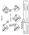
- Figure 2 shows an exemplary benefit of using the Figure 1 system, where a provider edge (PE) router-customer edge (CE) router interface/link has failed.
- PE provider edge
- CE customer edge
- the failed link between the Customer A edge router 114 for the site 108 and the service provider edge router 132 can be identified as impacting customer A's VPN.
- events associated with this interface/link failure are thus correlated with the affected VPN to provide useful information to the network administrator regarding the failure.
- the occurrence of an interface failure associated with this link can be displayed to the user.
- This can be provided to the network administrator with information identifying the source (interface 1 of provider edge router 1 (i.e., provider edge router 132)), and information identifying the impacted VPN (i.e., the VPN of Customer A).
- Figure 3 shows an exemplary MPLS view of a labeled switched path (LSP) overlay on the MPLS core of the Figure 1 service provider network 130.
- Figure 3 illustrates the service provider network 130 includes the edge routers 132-138, along with interior routers designated 302, 304, 306, 308 and 310.
- the interior provider router 306, labeled "P-3" is shown to include three interfaces labeled IF-1, IF-2 and IF-3.
- a labeled switched path 312 between the provider edge router 132 and the provider edge router 138 is shown to pass through the interior provider routers 304, 306 and 310 (labeled P-2, P-3 and P-5, respectively). Using this path, packets can pass between sites 1 and 3 for Customer A in Figure 1.
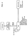
- FIG 4 shows an exemplary conceptual object model associated with the discovery and naming of VPNs in accordance with an exemplary embodiment of the present invention.
- any of "n" primary edge routers can include any number of VRF enabled interfaces (e.g., "n” interfaces).
- VRF-VRF adjacency can be determined using the VRF tables.
- VRF-VRF adjacency refers to those routers having VRF tables with information that indicates the routers communicate directly or indirectly with one another. For example, where a VRF table of a first router indicates that the router exports to a particular routing target, and the VRF table of a record router indicates that the second router imports data from the same routing target, adjacency is considered to exist.
- each VRF table is associated with an MPLS-VPN.
- Each MPLS-VPN can be identified by:
- VRF name is described by its association with the MPLS-VPN network.
- a route distinguisher is provided to indicate routes with which it is associated.
- Performance status and performance status time information can be included along with import and export router lists.
Landscapes
- Engineering & Computer Science (AREA)
- Computer Security & Cryptography (AREA)
- Computer Networks & Wireless Communication (AREA)
- Signal Processing (AREA)
- Data Exchanges In Wide-Area Networks (AREA)
Abstract
Description
- A method and system are disclosed for managing nodes of a computer network which communicate via connectivity services of a service provider, such as virtual private network (VPN) services.
- For example, a customer may have a network with nodes in multiple geographical locations, and a service provider can be used to connect these different locations. Because the service provider can provide connectivity services to multiple customers, multiple VPNs can be configured by the service provider.
- MultiProtocol Label Switching (MPLS) is an IETF initiative directed to enhancing Internet Protocol (IP) packet exchange by combining network link information such as bandwidth, latency and utilization, into layer L3 (IP) information. The inclusion of layer L2 network link information into layer L3 information can provide network administrators enhanced flexibility in managing network traffic.
- When a data packet enters an MPLS network, Label Edge Routers (LERs) provide the packets with a label, or identifier. The packets are classified, and assigned to corresponding Label Switch Paths (LSPs).
- In the case of connectivity services provided by third party service providers, the service providers may provide only limited management capabilities. For example, VPN service providers provide limited VPN management capabilities for use in managing an MPLS VPN network.
- A method is disclosed for managing network nodes which communicate via connectivity services of a service provider. An exemplary method includes discovering status and configuration information for each set of nodes grouped by the service provider; and assigning a name to each set of nodes.
- An exemplary system is also disclosed for managing network nodes which communicate via connectivity services of a service provider, comprising: a processor for discovering status and configuration information for each set of nodes grouped by the service provider, and for assigning a name to each set of nodes. A memory is provided for storing the status and configuration information for use by the processor.
- Exemplary embodiments, along with attendant features and advantages, will be described in the context of exemplary embodiments as shown in the Figures, wherein:
- Figure 1 illustrates an exemplary network which communicates via connectivity services of a service provider;
- Figure 2 illustrates an exemplary discovery process for detecting a fault in a network communication link;
- Figure 3 shows an exemplary Label Switch Path (LSP) overlaid on an MPLS VPN network; and
- Figure 4 shows a conceptual object model of network components used in accordance with an exemplary embodiment described herein.
- Figure 1 shows an exemplary system for managing network nodes which communicate via connectivity services of a service provider. The
exemplary system 100 includes aprocessor 102 and an associatedmemory 104. - A means, such as the
processor 102, is provided for discovering status and configuration information for each set of nodes grouped by a service provider, and for assigning a name to each set of nodes. A means, such as thememory 104, is provided for storing the status and configuration information discovered. - The
system 100, as shown in Figure 1, is associated with anetwork 101 of "Customer A." Customer A's network includesnodes 106 located amongmultiple sites site 1,site 2 andsite 3, respectively. The various sites can be physically (e.g., geographically) separated from one another. For example, an enterprise network will typically include nodes at an office location in a first geographical location, which are to interface with nodes associated with an office complex located in a second geographical location, that can be situated miles away from the first location. Each of the sites can include any number of nodes and routers. Acustomer edge router respective sites - To assist in understanding features described herein, Figure 1 illustrates a
second network 103 of a Customer B, havingnodes 120 located at each ofmultiple sites site 1 andsite 2, respectively. Eachsite customer edge router - The nodes of Customer A's network communicate via use of a
service provider network 130. Similarly, the nodes of customer B's network communicate via the sameservice provider network 130. The service provider provides connectivity services, such as VPN services, to customer networks. In an exemplary embodiment, the networks being managed are MPLS VPN networks, and each group of nodes is a VPN configured by the service provider. The service provider network includesedge routers - An administrator managing the MPLS VPN network of Customer A can, according to the exemplary embodiments described herein, be provided with status information for all VPNs configured in the environment. In addition, configuration information can be provided to indicate the location at which each VPN is deployed, and information regarding which edge routers are associated with each VPN. Exemplary embodiments use information regarding which router interface belongs to which VPN Routing and Forwarding (VRF) table to ascertain the status and configuration information.
- Exemplary embodiments provide an ability to view an inventory of all VPNs in the environment, and an ability to easily determine if an existing configuration matches an intended configuration. With regard to configuration matching, details regarding VPN, VRF, VRF-VRF neighbor, VRF-interface relationships, and so forth can be provided.
- The system for managing the network can use discovered data to perform an impact analysis based on infrastructure failures. The administrator can prioritize repair tasks based on an importance of a particular VPN (e.g., service level agreement (SLA) violations and so forth). Exemplary embodiments allow an administrator to diagnose and repair failures, thereby reducing MTTR.
- An exemplary method for managing network nodes which communicate via connectivity services of a service provider can be stored on a computer readable medium as a program which configures a computer processor, such as the
processor 102. An exemplary method will be described with respect to a VPN file which can, for example, be stored in an XML file or a database, using information obtained during VPN discovery. The information can be obtained from Management Information Bases (MIBs), such as those stored at routers and described with respect to CISCO IOS Software Release 12.OS, available from CISCO Systems. - The VPN discovery and storage of information discovered in a VPN information file will now be described. The VPN information to be discovered can include, for each VPN, details regarding provider edge (PE) routers, interfaces, VRF/VPN details and Interface-VPN relationships. In an exemplary XML file, an internal ID and VPN name is maintained for each MPLS VPN identified in the network. An exemplary XML File for an MPLS VPN having an internal ID of "1" and a VPN name "HP", referred to herein as VPN_INFO file, that can be created for use with HP's Network Node Manager™ (NNM) product, available from HP, is as follows:


- In the foregoing XML file, for the VPN "HP", each provider edge (PE) router is identified. For each provider edge router, the host name, SNMP address and all associated VRF tables are provided.
- In the foregoing example, an exemplary first provider edge router is associated with the host "service provider_PE1" (i.e.,
provider edge router 132 of Figure 1), having an SNMP address of "15.2.32.81" and having multiple VRF tables. A first of the VRF tables is VRF "HP" described as an HP site in Boeblingen, Germany with a route distinguisher of "100:12". - Note that for each VRF identifier, the interfaces associated with the VRF are provided. In the foregoing example, the VRF "HP" includes a first interface designated by an interface index of "3", an interface description as a "serial 0" interface and as having an object ID of "346". Those skilled in the art will appreciate that numerous interfaces can be associated with the VRF, and that numerous VRF's can be associated with the provider edge router in the foregoing example.
- Each VRF in the foregoing example, is also associated with export and import route target lists. Note that in the foregoing VFR example, an export route target list designates a routing target "100:12" and an import routing target list also designates routing target "100:12". In other words, the VFR associated with the provider edge included in the database routes packets to, and receives packets from route targets which communicate over a route designated "100:12", corresponding to a labeled switched path (LSP) of the MPLS network.
- The foregoing XML file also identifies VRF neighbors associated with each VFR included in the database. In the foregoing example, the first identifier VFR "HP" is indicated to have a VFR neighbor represented as a remote provider edge router labeled "
service provider_PE 2", corresponding toprovider edge router 134 in the Figure 1 example. Those skilled in the art will appreciate that multiple VFR neighbors can be associated with each VFR table. The foregoing XML file can include information similar to that described above with respect to each provider edge router, for each MPLS VPN. - Creation of the above exemplary XML file designated VPN_INFO can begin by building a seed file, based on all routers identified in the network database that are MPLS VPN enabled. Subsequent steps in the creation of the VPN_INFO file are based on this seed file. Exemplary pseudocode for creation of the foregoing VPN_INFO file is as follows:
- Seed: use filter to get list of ALL routers in network node database that are MPLS VPN enabled:
- For each router, get the IP address to be used for SNMP Queries
- For each router that is MPLS VPN enabled:
- Perform SNMP Queries to obtain:
- VRF Details from the VRF Table included in router MIB
- Interface to VRF Relationships from IF-Conf table
- Route Target Import/Export lists
- Perform SNMP Queries to obtain:
- For each Interface that has a VRF:
- Query node management database to obtain Interface (IF) information: (IFIndex; IFDescr; Object-id)
- VPN Objects can be created using the VRF information, such as, the Route Targets, to link various VRFs together. Upon creating the foregoing exemplary VPN_INFO file, the VPNs of the network can be identified using the following pseudocode:
- For each VRF object, examine list of Import and list of Export Route Targets.
- Two VRFs are considered part of the same VPN ONLY IF one of the VRFs has an Export Target matching that of the second one's Import Target.
- If VRF1 and VRF2 are identified as "neighbors" (using Import/Exports) AND VRF2 and VRF3 are identified as neighbors, all three are considered to belong to the same VPN
- Each identical VPN can be provided a name. Every VPN has an internal ID (obj-id) and a VPN-name (user-visible). Exemplary guidelines for implementing VPN naming are as follows:
- Using VPN internal ID and/or VPN name, try to pick a unique VRF name (at this point, uniqueness not guaranteed)
- User can override name selection through a configuration file
- A default naming algorithm can be invoked whereby multiple discoveries pick the same name (unless the set of VRF names changes).
- An exemplary VPN naming process is as follows:
- 1. If a user-configured file has any of the VRFs in this VPN, use that name; ELSE:
- 2. Use the Default naming method as follows:
- a. If ALL the VRFs within the VPN have the same name, use that name;
- b. ELSE, pick a VRF name within this VPN. E.G.: Pick lexically (alphabetically) smallest VRF Name that does
- NOT match with that of any VRF in other VPNs (i.e., multiple discoveries are considered to pick the same name, unless the set of VRF names changes).
- An alternate process for Default naming of VPN's can be implemented as follows:
- a. If ALL the VFR's within the VPN have the same name, use that name:
- b. ELSE, automatically do string matches (e.g., one VFR has the name "HP FC" and another has the name "HP PA", call the VPN "HP").
- Those skilled in the art will appreciate that any mechanism for naming the VPN including those processes noted above, can be implemented in any order desired by the user. In the foregoing example, HP FC and HP PA can correspond to two different customer sites, such as an HP site located at Ft. Collins and an HP site located at Palo Alto. Using the information acquired in the discovery process described above, the exemplary system described herein can determine that multiple sites are on the same VPN such that a common name can be used to describe the nodes associated with these sites. The string matching operation mentioned above, can for example, be used to identify the common name "HP" among the multiple VFR tables.
- An example of a user-configured file format for naming a VPN is as follows:

- Figure 2 shows an exemplary benefit of using the Figure 1 system, where a provider edge (PE) router-customer edge (CE) router interface/link has failed. In this example, the failed link between the Customer
A edge router 114 for thesite 108 and the serviceprovider edge router 132 can be identified as impacting customer A's VPN. In accordance with exemplary embodiments described herein, events associated with this interface/link failure are thus correlated with the affected VPN to provide useful information to the network administrator regarding the failure. - For example, as shown in the table of Figure 2, the occurrence of an interface failure associated with this link can be displayed to the user. This can be provided to the network administrator with information identifying the source (
interface 1 of provider edge router 1 (i.e., provider edge router 132)), and information identifying the impacted VPN (i.e., the VPN of Customer A). - Figure 3 shows an exemplary MPLS view of a labeled switched path (LSP) overlay on the MPLS core of the Figure 1
service provider network 130. Figure 3 illustrates theservice provider network 130 includes the edge routers 132-138, along with interior routers designated 302, 304, 306, 308 and 310. Theinterior provider router 306, labeled "P-3", is shown to include three interfaces labeled IF-1, IF-2 and IF-3. A labeled switchedpath 312 between theprovider edge router 132 and theprovider edge router 138 is shown to pass through theinterior provider routers sites - Figure 4 shows an exemplary conceptual object model associated with the discovery and naming of VPNs in accordance with an exemplary embodiment of the present invention. As shown in Figure 4, any of "n" primary edge routers can include any number of VRF enabled interfaces (e.g., "n" interfaces). For each interface, VRF-VRF adjacency can be determined using the VRF tables.
- VRF-VRF adjacency refers to those routers having VRF tables with information that indicates the routers communicate directly or indirectly with one another. For example, where a VRF table of a first router indicates that the router exports to a particular routing target, and the VRF table of a record router indicates that the second router imports data from the same routing target, adjacency is considered to exist.
- For each VRF, the following information can be included in the table:
- VRF_NAME
- DESCRIPTION
- ROUTE_DISTINGUISHER
- VPN_PERF_STATUS
- VPN_PERF_STATUS_TIME
- EXPORT_RT_LIST
- IMPORT_RT_LIST.
- As already discussed, each VRF table is associated with an MPLS-VPN. Each MPLS-VPN can be identified by:
- VPN NAME
- STATUS
- VPN_PERF_STATUS.
- In the foregoing information, a VRF name is described by its association with the MPLS-VPN network. A route distinguisher is provided to indicate routes with which it is associated. Performance status and performance status time information can be included along with import and export router lists.
- Although the present invention has been described in connection with embodiments thereof, it will be appreciated by those skilled in the art that additions, deletions, modifications, and substitutions not specifically described may be made without departing from the spirit and scope of the invention as defined in the appended claims.
Claims (10)
- Method for managing network nodes (106, 120) which communicate via connectivity services of a service provider (130), comprising:discovering status and configuration information for each set of nodes grouped by the service provider; andassigning a name to each set of nodes.
- Method according to claim 1, wherein the network is an MPLS VPN network, and wherein each set of nodes is a VPN configured by the service provider.
- Method according to claim 1, comprising:storing the status and configuration information in a memory (104).
- Method according to claim 3, wherein the status and configuration information is stored in an XML file.
- Method according to claim 1, wherein the status and configuration information includes a status for each VPN configured in the network.
- Method according to claim 1, wherein the status and configuration information indicates where each VPN is deployed.
- Method according to claim 1, wherein the status and configuration information indicates which edge routers (114, 116, 118, 126, 128) of the network are involved with which VPN.
- Method according to claim 1, wherein the discovering is performed using information which associates a router interface with a VPN routing and forwarding (VRF) table.
- System for performing the method of claim 1, comprising:a processor (102) for discovering status and configuration information for each set of nodes grouped by the service provider, and for assigning a name to each set of nodes; anda memory (104) for storing the status and configuration information for use by the processor.
- A computer readable medium for storing a computer program which configures a computer processor to perform the method of claim 1.
Applications Claiming Priority (1)
| Application Number | Priority Date | Filing Date | Title |
|---|---|---|---|
| US10/953,281 US7643434B2 (en) | 2004-09-30 | 2004-09-30 | Method and system for managing network nodes which communicate via connectivity services of a service provider |
Publications (2)
| Publication Number | Publication Date |
|---|---|
| EP1643680A1 true EP1643680A1 (en) | 2006-04-05 |
| EP1643680B1 EP1643680B1 (en) | 2008-03-19 |
Family
ID=35447993
Family Applications (1)
| Application Number | Title | Priority Date | Filing Date |
|---|---|---|---|
| EP05018947A Ceased EP1643680B1 (en) | 2004-09-30 | 2005-08-31 | Method and system for managing network nodes in MPLS-VPN networks |
Country Status (2)
| Country | Link |
|---|---|
| US (1) | US7643434B2 (en) |
| EP (1) | EP1643680B1 (en) |
Families Citing this family (32)
| Publication number | Priority date | Publication date | Assignee | Title |
|---|---|---|---|---|
| US8179902B2 (en) * | 2005-07-15 | 2012-05-15 | Cisco Technology, Inc. | Method and system for automatic generation of route distinguishers for virtual private networks |
| US7536187B2 (en) * | 2005-08-23 | 2009-05-19 | Cisco Technology, Inc. | Supporting communication sessions at a mobile node |
| US7593352B2 (en) * | 2006-06-02 | 2009-09-22 | Cisco Technology, Inc. | Discovering MPLS VPN services in a network |
| US8477620B2 (en) * | 2006-12-27 | 2013-07-02 | Entry Point, Llc | System and method to provide multiple private networks using PBB |
| US8582580B2 (en) | 2006-12-27 | 2013-11-12 | Entry Point, Llc | System and method to provide multiple private networks using PBB/TE |
| US7843944B2 (en) * | 2006-12-27 | 2010-11-30 | Entry Point, Llc | System and method to provide multiple private networks using MPLS |
| US8432894B2 (en) * | 2007-02-27 | 2013-04-30 | Alcatel Lucent | Asymmetrical forwarding in layer 3 IP VPNs |
| US8102758B2 (en) * | 2007-03-05 | 2012-01-24 | Cisco Technology, Inc. | Analyzing virtual private network failures |
| US8885634B2 (en) * | 2007-11-30 | 2014-11-11 | Ciena Corporation | Systems and methods for carrier ethernet using referential tables for forwarding decisions |
| US8169922B2 (en) * | 2007-12-21 | 2012-05-01 | At&T Intellectual Property I, Lp | Diagnosing problems associated with route groups in a network |
| US20090304003A1 (en) * | 2008-05-27 | 2009-12-10 | Olivier Huynh Van | Global Virtual VPN |
| US8837491B2 (en) | 2008-05-27 | 2014-09-16 | Glue Networks | Regional virtual VPN |
| US9319300B2 (en) * | 2008-12-09 | 2016-04-19 | Glue Networks, Inc. | Systems and methods for determining endpoint configurations for endpoints of a virtual private network (VPN) and deploying the configurations to the endpoints |
| US9524167B1 (en) * | 2008-12-10 | 2016-12-20 | Amazon Technologies, Inc. | Providing location-specific network access to remote services |
| US7944857B2 (en) * | 2009-01-12 | 2011-05-17 | Hewlett-Packard Development Company, L.P. | Method and system for deriving tunnel path information in MPLS networks |
| US8000265B2 (en) * | 2009-04-29 | 2011-08-16 | Hewlett-Packard Development Company, L.P. | Method and system for determining network topology of a virtual private network in multi protocol label switching (MPLS) based virtual private networks (VPNs) |
| US8144624B2 (en) * | 2009-10-22 | 2012-03-27 | Hewlett-Packard Development Company, L.P. | Method and system for discovering a pure hub-and-spoke topology |
| US8995301B1 (en) | 2009-12-07 | 2015-03-31 | Amazon Technologies, Inc. | Using virtual networking devices to manage routing cost information |
| US9036504B1 (en) | 2009-12-07 | 2015-05-19 | Amazon Technologies, Inc. | Using virtual networking devices and routing information to associate network addresses with computing nodes |
| US7937438B1 (en) | 2009-12-07 | 2011-05-03 | Amazon Technologies, Inc. | Using virtual networking devices to manage external connections |
| US9203747B1 (en) | 2009-12-07 | 2015-12-01 | Amazon Technologies, Inc. | Providing virtual networking device functionality for managed computer networks |
| US7953865B1 (en) | 2009-12-28 | 2011-05-31 | Amazon Technologies, Inc. | Using virtual networking devices to manage routing communications between connected computer networks |
| US8224971B1 (en) * | 2009-12-28 | 2012-07-17 | Amazon Technologies, Inc. | Using virtual networking devices and routing information to initiate external actions |
| US7991859B1 (en) | 2009-12-28 | 2011-08-02 | Amazon Technologies, Inc. | Using virtual networking devices to connect managed computer networks |
| US8867406B2 (en) * | 2010-04-07 | 2014-10-21 | Hewlett-Packard Development Company, L.P. | System and method for automated discovery of customer-edge devices and interface connections in a virtual-private-networking environment |
| US9143408B2 (en) | 2012-07-30 | 2015-09-22 | Hewlett-Packard Development Company, L.P. | Interprovider virtual private network path identification |
| US9760528B1 (en) | 2013-03-14 | 2017-09-12 | Glue Networks, Inc. | Methods and systems for creating a network |
| US9928082B1 (en) | 2013-03-19 | 2018-03-27 | Gluware, Inc. | Methods and systems for remote device configuration |
| CN104468408B (en) * | 2013-09-22 | 2018-04-06 | 中国电信股份有限公司 | For dynamically adjusting the method and control centre's server of service bandwidth |
| US9785412B1 (en) | 2015-02-27 | 2017-10-10 | Glue Networks, Inc. | Methods and systems for object-oriented modeling of networks |
| US10367700B2 (en) | 2017-06-05 | 2019-07-30 | Hewlett Packard Enterprise Development Lp | Node identification using templates |
| US10929862B2 (en) | 2018-11-02 | 2021-02-23 | At&T Intellectual Property I, L.P. | Telecommunication network configuration from feature-based extrapolation |
Citations (2)
| Publication number | Priority date | Publication date | Assignee | Title |
|---|---|---|---|---|
| CA2474879A1 (en) * | 2001-07-03 | 2003-01-16 | Imagine Broadband Limited | Method and system for monitoring service performance over a virtual private network connection by simulating end user activity |
| EP1517482A1 (en) * | 2003-09-18 | 2005-03-23 | Hewlett-Packard Development Company, L.P. | Discovery of virtual private networks |
Family Cites Families (27)
| Publication number | Priority date | Publication date | Assignee | Title |
|---|---|---|---|---|
| US6678835B1 (en) * | 1999-06-10 | 2004-01-13 | Alcatel | State transition protocol for high availability units |
| US6693878B1 (en) * | 1999-10-15 | 2004-02-17 | Cisco Technology, Inc. | Technique and apparatus for using node ID as virtual private network (VPN) identifiers |
| JP3790655B2 (en) * | 2000-03-06 | 2006-06-28 | 富士通株式会社 | Label switch network system |
| US7272643B1 (en) * | 2000-09-13 | 2007-09-18 | Fortinet, Inc. | System and method for managing and provisioning virtual routers |
| JP2002335245A (en) * | 2001-05-10 | 2002-11-22 | Allied Tereshisu Kk | Node detection method, node detection device, and node detection program |
| US7450505B2 (en) * | 2001-06-01 | 2008-11-11 | Fujitsu Limited | System and method for topology constrained routing policy provisioning |
| US7743126B2 (en) * | 2001-06-28 | 2010-06-22 | Hewlett-Packard Development Company, L.P. | Migrating recovery modules in a distributed computing environment |
| US7362701B2 (en) * | 2002-01-14 | 2008-04-22 | Sun Microsystems, Inc. | Customer-based service system including a cascaded pipeline with self-monitoring relays |
| US20030219022A1 (en) * | 2002-01-28 | 2003-11-27 | Hughes Electronics | Method and system for utilizing virtual private network (VPN) connections in a performance enhanced network |
| SE0200640D0 (en) * | 2002-02-28 | 2002-02-28 | Ericsson Telefon Ab L M | Arrangement and method for routing in virtual private network |
| US7327675B1 (en) * | 2002-08-01 | 2008-02-05 | At&T Corp. | Fairness of capacity allocation for an MPLS-based VPN |
| US7653746B2 (en) * | 2002-08-02 | 2010-01-26 | University Of Southern California | Routable network subnet relocation systems and methods |
| US20040078105A1 (en) * | 2002-09-03 | 2004-04-22 | Charles Moon | System and method for workflow process management |
| US7519834B1 (en) * | 2003-01-24 | 2009-04-14 | Nortel Networks Limited | Scalable method and apparatus for transforming packets to enable secure communication between two stations |
| US7486659B1 (en) * | 2003-02-24 | 2009-02-03 | Nortel Networks Limited | Method and apparatus for exchanging routing information between virtual private network sites |
| US20040223497A1 (en) * | 2003-05-08 | 2004-11-11 | Onvoy Inc. | Communications network with converged services |
| US7715380B2 (en) * | 2003-06-19 | 2010-05-11 | Cisco Technology, Inc. | Apparatus and methods for handling shared services through virtual route forwarding (VRF)-aware-NAT |
| US7409712B1 (en) * | 2003-07-16 | 2008-08-05 | Cisco Technology, Inc. | Methods and apparatus for network message traffic redirection |
| US7075933B2 (en) * | 2003-08-01 | 2006-07-11 | Nortel Networks, Ltd. | Method and apparatus for implementing hub-and-spoke topology virtual private networks |
| US7848259B2 (en) * | 2003-08-01 | 2010-12-07 | Opnet Technologies, Inc. | Systems and methods for inferring services on a network |
| US8010643B2 (en) * | 2003-08-01 | 2011-08-30 | Opnet Technologies Inc | System and methods for simulating traffic generation |
| US7698456B2 (en) * | 2003-09-29 | 2010-04-13 | Cisco Technology, Inc. | Methods and apparatus to support routing of information |
| US20050190757A1 (en) * | 2004-02-27 | 2005-09-01 | Cisco Technology Inc. | Interworking between Ethernet and non-Ethernet customer sites for VPLS |
| US20060251114A1 (en) * | 2004-03-25 | 2006-11-09 | Jayasimha Nuggehalli | Approach for collecting and reporting status data from network devices |
| US7568047B1 (en) * | 2004-04-30 | 2009-07-28 | Nortel Networks Limited | Method and apparatus for adaptive service label management |
| US7366182B2 (en) * | 2004-08-13 | 2008-04-29 | Qualcomm Incorporated | Methods and apparatus for efficient VPN server interface, address allocation, and signaling with a local addressing domain |
| US7623535B2 (en) * | 2004-09-09 | 2009-11-24 | Cisco Technology, Inc. | Routing protocol support for half duplex virtual routing and forwarding instance |
-
2004
- 2004-09-30 US US10/953,281 patent/US7643434B2/en active Active
-
2005
- 2005-08-31 EP EP05018947A patent/EP1643680B1/en not_active Ceased
Patent Citations (2)
| Publication number | Priority date | Publication date | Assignee | Title |
|---|---|---|---|---|
| CA2474879A1 (en) * | 2001-07-03 | 2003-01-16 | Imagine Broadband Limited | Method and system for monitoring service performance over a virtual private network connection by simulating end user activity |
| EP1517482A1 (en) * | 2003-09-18 | 2005-03-23 | Hewlett-Packard Development Company, L.P. | Discovery of virtual private networks |
Non-Patent Citations (4)
| Title |
|---|
| CARUGI NORTEL NETWORKS D MCDYSAN MCI (CO-EDITORS) M: "Service requirements for Layer 3 Provider Provisioned Virtual Private Networks: <draft-ietf-ppvpn-requirements-06.txt>", IETF STANDARD-WORKING-DRAFT, INTERNET ENGINEERING TASK FORCE, IETF, CH, vol. ppvpn, no. 6, April 2003 (2003-04-01), XP015003086, ISSN: 0000-0004 * |
| DONG-JIN SHIN ET AL: "Design and Implementation of Configuration Management for the MPLS Network", KNOM REVIEW, vol. 5, no. 1, December 2002 (2002-12-01), XP002359281, Retrieved from the Internet <URL:http://dpnm.postech.ac.kr/knom/knom-review/v5n2/7.pdf> [retrieved on 20051215] * |
| PAUL KNIGHT (EDITOR) HAMID OULD-BRAHIM NORTEL NETWORKS BRYAN GLEESON NOKIA: "Network based IP VPN Architecture using Virtual Routers", IETF STANDARD-WORKING-DRAFT, INTERNET ENGINEERING TASK FORCE, IETF, CH, vol. l3vpn, no. 2, April 2004 (2004-04-01), XP015038544, ISSN: 0000-0004 * |
| THOMAS D NADEAU CISCO SYSTEMS ET AL: "MPLS/BGP Layer 3 Virtual Private Network Management Information Base", IETF STANDARD-WORKING-DRAFT, INTERNET ENGINEERING TASK FORCE, IETF, CH, vol. l3vpn, no. 5, August 2004 (2004-08-01), XP015022032, ISSN: 0000-0004 * |
Also Published As
| Publication number | Publication date |
|---|---|
| US7643434B2 (en) | 2010-01-05 |
| US20060072589A1 (en) | 2006-04-06 |
| EP1643680B1 (en) | 2008-03-19 |
Similar Documents
| Publication | Publication Date | Title |
|---|---|---|
| US7643434B2 (en) | Method and system for managing network nodes which communicate via connectivity services of a service provider | |
| US8526325B2 (en) | Detecting and identifying connectivity in a network | |
| US7463639B1 (en) | Edge devices for providing a transparent LAN segment service and configuring such edge devices | |
| EP1427152B1 (en) | Virtual local area network auto-discovery methods | |
| JP4833292B2 (en) | Ethernet GMPLS control | |
| US9450779B2 (en) | Edge link discovery | |
| US20020021675A1 (en) | System and method for packet network configuration debugging and database | |
| CN101180839B (en) | Method and system for generating and maintaining service level diagnostic test point library | |
| EP1393503B1 (en) | Method and system for determining network characteristics using routing protocols | |
| US9391886B2 (en) | Identification of the paths taken through a network of interconnected devices | |
| US9544217B2 (en) | Identification of paths in a network of mixed routing/switching devices | |
| JP6193473B2 (en) | Computer-implemented method, computer program product and computer | |
| US20070097991A1 (en) | Method and system for discovering and providing near real-time updates of VPN topologies | |
| WO2005031532A2 (en) | Method and apparatus for modeling and analyzing mpls and virtual private networks | |
| US9531598B2 (en) | Querying a traffic forwarding table | |
| EP2586157A1 (en) | Network management | |
| CN101247267B (en) | Method and device for automatic discovery of three-layer virtual private network topology in network management system | |
| US20040215781A1 (en) | Techniques for determining device connectivity in a network using protocol-specific connectivity information | |
| Pandey et al. | SNMP‐based enterprise IP network topology discovery | |
| CN112737951B (en) | End-to-end SR control method, system and readable storage medium in public and private network mixed scene | |
| US7990945B1 (en) | Method and apparatus for provisioning a label switched path across two or more networks | |
| CN120750752A (en) | L3VPN service restoration method and system supporting multiple service models |
Legal Events
| Date | Code | Title | Description |
|---|---|---|---|
| PUAI | Public reference made under article 153(3) epc to a published international application that has entered the european phase |
Free format text: ORIGINAL CODE: 0009012 |
|
| AK | Designated contracting states |
Kind code of ref document: A1 Designated state(s): AT BE BG CH CY CZ DE DK EE ES FI FR GB GR HU IE IS IT LI LT LU LV MC NL PL PT RO SE SI SK TR |
|
| AX | Request for extension of the european patent |
Extension state: AL BA HR MK YU |
|
| 17P | Request for examination filed |
Effective date: 20060907 |
|
| 17Q | First examination report despatched |
Effective date: 20061113 |
|
| AKX | Designation fees paid |
Designated state(s): GB |
|
| REG | Reference to a national code |
Ref country code: DE Ref legal event code: 8566 |
|
| GRAP | Despatch of communication of intention to grant a patent |
Free format text: ORIGINAL CODE: EPIDOSNIGR1 |
|
| GRAS | Grant fee paid |
Free format text: ORIGINAL CODE: EPIDOSNIGR3 |
|
| GRAA | (expected) grant |
Free format text: ORIGINAL CODE: 0009210 |
|
| AK | Designated contracting states |
Kind code of ref document: B1 Designated state(s): GB |
|
| REG | Reference to a national code |
Ref country code: GB Ref legal event code: FG4D |
|
| PLBE | No opposition filed within time limit |
Free format text: ORIGINAL CODE: 0009261 |
|
| STAA | Information on the status of an ep patent application or granted ep patent |
Free format text: STATUS: NO OPPOSITION FILED WITHIN TIME LIMIT |
|
| 26N | No opposition filed |
Effective date: 20081222 |
|
| PGFP | Annual fee paid to national office [announced via postgrant information from national office to epo] |
Ref country code: GB Payment date: 20150724 Year of fee payment: 11 |
|
| REG | Reference to a national code |
Ref country code: GB Ref legal event code: 732E Free format text: REGISTERED BETWEEN 20160818 AND 20160824 |
|
| GBPC | Gb: european patent ceased through non-payment of renewal fee |
Effective date: 20160831 |
|
| PG25 | Lapsed in a contracting state [announced via postgrant information from national office to epo] |
Ref country code: GB Free format text: LAPSE BECAUSE OF NON-PAYMENT OF DUE FEES Effective date: 20160831 |