EP1643663B1 - A addressing method of quanta network and quanta network router - Google Patents
A addressing method of quanta network and quanta network router Download PDFInfo
- Publication number
- EP1643663B1 EP1643663B1 EP04738287A EP04738287A EP1643663B1 EP 1643663 B1 EP1643663 B1 EP 1643663B1 EP 04738287 A EP04738287 A EP 04738287A EP 04738287 A EP04738287 A EP 04738287A EP 1643663 B1 EP1643663 B1 EP 1643663B1
- Authority
- EP
- European Patent Office
- Prior art keywords
- wavelength
- network
- nodes
- optical
- quantum
- Prior art date
- Legal status (The legal status is an assumption and is not a legal conclusion. Google has not performed a legal analysis and makes no representation as to the accuracy of the status listed.)
- Expired - Lifetime
Links
- 238000000034 method Methods 0.000 title claims abstract description 19
- 230000003287 optical effect Effects 0.000 claims description 58
- 239000000835 fiber Substances 0.000 claims description 10
- 230000008878 coupling Effects 0.000 claims description 7
- 238000010168 coupling process Methods 0.000 claims description 7
- 238000005859 coupling reaction Methods 0.000 claims description 7
- 230000002441 reversible effect Effects 0.000 claims description 6
- 239000000758 substrate Substances 0.000 claims description 2
- 230000006854 communication Effects 0.000 abstract description 30
- 238000004891 communication Methods 0.000 abstract description 29
- 230000005540 biological transmission Effects 0.000 abstract description 9
- 238000005516 engineering process Methods 0.000 description 9
- 238000010586 diagram Methods 0.000 description 5
- 238000002955 isolation Methods 0.000 description 3
- 238000005259 measurement Methods 0.000 description 3
- 239000002245 particle Substances 0.000 description 3
- 238000012546 transfer Methods 0.000 description 3
- 238000006243 chemical reaction Methods 0.000 description 2
- 238000004040 coloring Methods 0.000 description 2
- 238000003780 insertion Methods 0.000 description 2
- 230000037431 insertion Effects 0.000 description 2
- 230000006978 adaptation Effects 0.000 description 1
- 230000003321 amplification Effects 0.000 description 1
- 238000010367 cloning Methods 0.000 description 1
- 238000013461 design Methods 0.000 description 1
- 230000006866 deterioration Effects 0.000 description 1
- 238000003199 nucleic acid amplification method Methods 0.000 description 1
- 238000011160 research Methods 0.000 description 1
- 230000003068 static effect Effects 0.000 description 1
- 238000006467 substitution reaction Methods 0.000 description 1
Images


Classifications
-
- H—ELECTRICITY
- H04—ELECTRIC COMMUNICATION TECHNIQUE
- H04L—TRANSMISSION OF DIGITAL INFORMATION, e.g. TELEGRAPHIC COMMUNICATION
- H04L9/00—Cryptographic mechanisms or cryptographic arrangements for secret or secure communications; Network security protocols
- H04L9/08—Key distribution or management, e.g. generation, sharing or updating, of cryptographic keys or passwords
- H04L9/0816—Key establishment, i.e. cryptographic processes or cryptographic protocols whereby a shared secret becomes available to two or more parties, for subsequent use
- H04L9/0852—Quantum cryptography
- H04L9/0855—Quantum cryptography involving additional nodes, e.g. quantum relays, repeaters, intermediate nodes or remote nodes
-
- B—PERFORMING OPERATIONS; TRANSPORTING
- B82—NANOTECHNOLOGY
- B82Y—SPECIFIC USES OR APPLICATIONS OF NANOSTRUCTURES; MEASUREMENT OR ANALYSIS OF NANOSTRUCTURES; MANUFACTURE OR TREATMENT OF NANOSTRUCTURES
- B82Y10/00—Nanotechnology for information processing, storage or transmission, e.g. quantum computing or single electron logic
-
- H—ELECTRICITY
- H04—ELECTRIC COMMUNICATION TECHNIQUE
- H04B—TRANSMISSION
- H04B10/00—Transmission systems employing electromagnetic waves other than radio-waves, e.g. infrared, visible or ultraviolet light, or employing corpuscular radiation, e.g. quantum communication
- H04B10/27—Arrangements for networking
-
- H—ELECTRICITY
- H04—ELECTRIC COMMUNICATION TECHNIQUE
- H04B—TRANSMISSION
- H04B10/00—Transmission systems employing electromagnetic waves other than radio-waves, e.g. infrared, visible or ultraviolet light, or employing corpuscular radiation, e.g. quantum communication
- H04B10/70—Photonic quantum communication
-
- H—ELECTRICITY
- H04—ELECTRIC COMMUNICATION TECHNIQUE
- H04J—MULTIPLEX COMMUNICATION
- H04J14/00—Optical multiplex systems
- H04J14/02—Wavelength-division multiplex systems
-
- H—ELECTRICITY
- H04—ELECTRIC COMMUNICATION TECHNIQUE
- H04L—TRANSMISSION OF DIGITAL INFORMATION, e.g. TELEGRAPHIC COMMUNICATION
- H04L2101/00—Indexing scheme associated with group H04L61/00
- H04L2101/60—Types of network addresses
- H04L2101/618—Details of network addresses
-
- H—ELECTRICITY
- H04—ELECTRIC COMMUNICATION TECHNIQUE
- H04Q—SELECTING
- H04Q2213/00—Indexing scheme relating to selecting arrangements in general and for multiplex systems
- H04Q2213/13339—Ciphering, encryption, security
Definitions
- This invention relates to an addressing method and apparatus which can be used for network communication via light transmission technology, and more particularly relates to an addressing method and apparatus for quantum information, including quantum communication and quantum computation network system.
- Quantum information technology is a new scientific field which starts in 1990s. There are many problems being researched, and it is not applied on a large scale, so there will not be any open technologies relate to this invention. According to the experience about classical network information technology, quantum network information technology will be the kernel technology of quantum communication. Comparing with classical communication and considering the characteristics of quantum communication, quantum network system must satisfy these basic capability requirements:
- US 2003/002674A1 discloses a quantum cryptography multi-node communication system in which a transmission node transmits a light signal as a time series of photons to a reception node through a quantum communication channel, a quantum state of the photons is modulated, and transmits a quantum state sequence to the reception node; the reception node predetermines a quantum state sequence, receives the light signal transmitted from the transmission node, measures quantum states of the received light signals, and determines presence or absence of interception based on the predetermined quantum state sequence, the transmitted quantum state sequence and the measured quantum states.
- each nodes can communication each other but they need six wavelengths for four nodes network, and nC2 wavelengths for n nodes network;
- the third embodiment can transfer the quantum state between any two nodes, but most of the signal photons should transfer cross some other receiver nodes, it is not a best protocol for security communication; on other hand, this embodiment still need n+1 wavelengths for n nodes network, and also the optical passive wavelength combiner became complicated in this embodiment.
- JP His-130048 discloses an access control method in a local area network and its node equipment, in which the deterioration in communication quality is prevented while an optical signal is not modified with use of optical electric conversion, each node is allowed to receive only a required packet and not to receive an undesired packet but to pass through it.
- this document is only related to a conventional WDM scheme far away from the quantum communication field.
- WO 01/67676 A2 discloses a dual-mode virtual network addressing scheme in which reduced length addresses (referred to as short addresses) are substituted for standard addresses (referred to as long addresses) for traffic whose source or destination is internal to a given virtual network topology.
- short addresses reduced length addresses
- long addresses standard addresses
- this document is only related to the substitutions between the short addresses and the long addresses, and keeps silence about the quantum communications.
- P. D. Townsend et. al. proposes a quantum cryptography systems for passive optical networks in " Design of Quantum Cryptography Systems for Passive Optical Networks" (Electronics Letters, IEE Stevenage, GB LNKD-DOI: 10.1049/EL: 19941255, vol. 30, no. 22, October 27, 1994, pages 1875-1877).
- P. D. Townsend et. al . describes adaptations of the existing quantum cryptography protocols and equipment configurations that allow secure key distribution to be performed on a variety of multiuser passive optical network (PON) architectures.
- PON passive optical network
- the network includes at least three nodes, and the method comprises steps of: appointing each node an address serial number; sending photon signals having different wavelengths from each node to other nodes, wherein each of the photon signals regards signal source wavelength and node address as an addressing badge, said addressing badge is made up of two parts, one part is determined by the wavelength of the photon signal which the node sends, the other part is determined by the address serial number of the node; and determining, by each node, where the photon signals come from by using the addressing badges of the photon signals.
- the number of said signal source wavelength is N; when the number of nodes is even, the number of said signal source wavelength is N-1; here N is the number of nodes in the network.
- Said photon signal is optical quantum state signal, or classical optical signal.
- This addressing method can transmit photon signals having different wavelengths from any node in the network to appointed other node, this kind of transmission is one and only in the network, transmission direction is reversible, that means any node can transmit and receive photon signal, sender aforehand knows where the photon signal having certain wavelength is sent to, receiver knows where the photon signal he receives comes from by measuring the wavelength of the photon signal.
- Said network can have unlimited amount of nodes.
- Said photon signal can be a quantum signal, e.g. single photon or entangled photons; said wavelength means a wavelength interval. When the signal is optical quantum state, the communication process is quantum communication.
- This invention provides a quantum network router to implement said addressing method, it includes a photon signal allocator, the photon signal allocator includes N sets of optical component, here N is the number of nodes in the network, one end of every optical component is mix-wavelength interface, the other end includes separate wavelength interfaces; and an external interface comprising mix-wavelength interfaces of optical components, wherein the number of separate wavelength interfaces is at least N-1, every separate wavelength interface transmits different photon signals having different wavelengths, separate wavelength interfaces of different optical components, which transmit the same wavelength signals, connect one to one.
- N When N is even, said separate wavelength interfaces of optical components are the same, the total number of wavelength used in the whole quantum network router is N-1; when N is odd, any two optical components have one different separate wavelength interface, the total number of wavelength used in the whole quantum network router is N.
- said optical components are the same, each one has three separate wavelength interfaces, i.e. ⁇ 1, ⁇ 2, ⁇ 3, the total number of wavelength used in the router is three; for router of three optical components, each component has two separate wavelength interfaces, but they are not the same, i.e. No.1 component has ⁇ 1 and ⁇ 2, No. 2 has ⁇ 2 and ⁇ 3, No.3 has ⁇ 3 and ⁇ 1, the total number of wavelength used in the router is three too.
- Said optical component can be made up of integrated or separate dispersive and accessorial passive optical components.
- Said optical component can be reversible wavelength division multiplexer.
- Said optical connection can be achieved via fiber, wave-guide, free space or other optical medium.
- Said optical connection can add collimating, coupling or reflecting optical passive components in the optical path to improve the optical capability of the connection.
- Said optical components of the whole quantum network router include dispersive, collimating, orienting or coupling components, can be integrated with wave-guide substrate totally or partially.
- any router can be constructed according to this theorem.
- the correspondence principle is: vertex in edge coloring theorem corresponds to optical component in quantum network router; color corresponds to wavelength (i.e. separate wavelength interface in said optical component).
- vertex in edge coloring theorem corresponds to optical component in quantum network router; color corresponds to wavelength (i.e. separate wavelength interface in said optical component).
- wavelength i.e. separate wavelength interface in said optical component.
- Said photon signal can be transmitted from one node to another, reverse transmission is also allowed.
- Said reversible wavelength division multiplexer comprises dispersive part, front/back collimating part and input/output coupler, wherein dispersive part can be filter, raster or dispersive prism.
- the quantum network router of this invention can achieve: receiving photon signals having different wavelengths from all nodes in the network, transmitting the photon signals having different wavelengths which have same aim to their destination by division and coupling, these photon signals can finally be transmitted to certain user by arterial fiber.
- the working mode of this router won't destroy the quantum state and its coherence, there is not crosstalk either, every path is exclusive, no path superposition or signal loss, user can know where the signal comes from by simply measurement. All above satisfy the basic requirement of network.
- the addressing method and quantum network router in this invention regard sender's address and wavelength of quantum state as addressing badge, provides an apparatus of quantum network according to said addressing method, can satisfy the basic requirements of quantum network.
- quantum network router which is made up of commercial wavelength division multiplexers
- Quantum network router can be made up of commercial wavelength division multiplexers according to the principle of the invention.
- Fig. 1 shows a typically block diagram of internal structure of 4 nodes quantum network router.
- 1-1 ⁇ 1-4 are the same commercial wavelength division multiplexers
- ⁇ 1, ⁇ 2, ⁇ 3 are different wavelengths (in fact it is wave band of certain width) which should satisfy the requirement of insertion loss and isolation
- 2-1-2-6 are connections between separate wavelength interfaces which have the same wavelength, they can be optical paths comprising single mode fiber, separate component or wave-guide
- 3-1 ⁇ 3-4 are mix-wavelength interfaces, and can be connected with users by arterial fiber.
- FIG.2 shows internal structure of three nodes quantum network router, wherein 4-1 ⁇ 4-3 are wavelength division multiplexers, the difference from four nodes router is, every multiplexer has different wavelengths, 4-1 has ⁇ 1 and ⁇ 2, 4-2 has ⁇ 2 and ⁇ 3, 4-3 has ⁇ 3 and ⁇ 1, the total number of wavelength is three.
- 5-1-5-3 are connections between separate wavelength interfaces which have the same wavelength, they can be optical paths comprising single mode fiber, separate component or wave-guide; 6-1 ⁇ 6-3 are mix-wavelength interfaces, and can be connected with users by arterial fiber.
- this three nodes router can be looked as a special four nodes router in FIG.1 with one node and all connections with it disappeared.
- Any N nodes router can be constructed with multiplexers according to principle above described, router with odd nodes is similar to FIG.2 , and router with even nodes is similar to FIG.1 .
- Quantum network router can be made up of separate passive optical components instead of making wavelength division multiplexer first and then constructing quantum network router.
- This kind of router with N nodes can be made up of N dispersive components and accessorial orienting parts, e.g. collimating, coupling or reflecting optical passive components, prism or other refracting device.
- FIG.3 shows the internal structure of four nodes quantum network router which is made up of separate components.
- 7-1 ⁇ 7-4 are dispersive components and can achieve splitting and coupling of signal, they can be prism, filter or raster.
- 8-1 ⁇ 8-4 and 9-1 ⁇ 9-4 are front/back collimating system; its function is collimating and focalizing of ray.
- 10-1-10-4 are orienting components, its function is orienting ray to certain dispersive component; 11-1 ⁇ 11-4 input/output couplers; they connect with users by arterial fiber.
- Quantum network router can be made up of integrated optical components.
- N nodes router can be made up of N integrated dispersive components and orienting wave-guide.
- FIG.4 shows four nodes integrated quantum network router. 12-1 ⁇ 12-4 are integrated raster, their function is, separate mix-wavelength signal to single wavelength signals or reverse; 13-1 ⁇ 13-6 are wave-guide for single wavelength signal, transmit the signal to raster; 14-1 ⁇ 14-4 are mix-wavelength interfaces, they connect with users by arterial fiber.
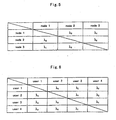
- FIG. 5 and FIG.6 show the forms of IP address for three nodes and four nodes quantum network router. For router with more than four nodes, there is also a form of IP address, form for odd nodes router is similar to FIG.5 , form for even nodes router is similar to FIG.6 .
Landscapes
- Engineering & Computer Science (AREA)
- Physics & Mathematics (AREA)
- Computer Networks & Wireless Communication (AREA)
- Signal Processing (AREA)
- Electromagnetism (AREA)
- Chemical & Material Sciences (AREA)
- Nanotechnology (AREA)
- Theoretical Computer Science (AREA)
- Computing Systems (AREA)
- Mathematical Physics (AREA)
- Computer Security & Cryptography (AREA)
- Crystallography & Structural Chemistry (AREA)
- Optics & Photonics (AREA)
- Optical Communication System (AREA)
- Data Exchanges In Wide-Area Networks (AREA)
Abstract
Description
- This invention relates to an addressing method and apparatus which can be used for network communication via light transmission technology, and more particularly relates to an addressing method and apparatus for quantum information, including quantum communication and quantum computation network system.
- Quantum information technology is a new scientific field which starts in 1990s. There are many problems being researched, and it is not applied on a large scale, so there will not be any open technologies relate to this invention. According to the experience about classical network information technology, quantum network information technology will be the kernel technology of quantum communication. Comparing with classical communication and considering the characteristics of quantum communication, quantum network system must satisfy these basic capability requirements:
- 1. multi-user
More than two users can exchange information and share resource at the same time. - 2. Extensibility
The number of users can increase and should not be limited theoretically. - 3. independence of the users
This should include two parts: first, the existence and movement of any user only affect those users who exchange information with this user, not the whole network; second, the movement of any user should not be affected by other users except for the one who exchange information with this user, namely crosstalk. - 4. Any user in the network should have one and only address or internal serial number (e.g. IP address in classical network), with this address, user can easily distinguish and connect to the user he want to communicate with, the user who is connected can also make sure which user he is talking to.
- Special requirements of quantum network:
- 5. Network system should keep quantum coherence (except receiving and measurement), that means decoherence process should be as weak as possible, and system should not have any photoelectric or electrooptic conversion process except for receiving and measurement.
- 6. There should not be any amplification of quantum signal inside the network system. This is the basic requirement of quantum no-cloning theorem.
- Up to now, there are no quantum network framework theory and technology accord with all the requirements above. The research on quantum key distribution over network has made the biggest progress in this field; existing main technologies come down to:
- 1. tree topology network
This network has two working modes. One mode is, sending modulated single photons to multiple receivers randomly by fibered beam splitters, and then making quantum key distribution between sender and receivers. This mode needs a control center, all users have to share information with control center, that would be unendurable in secure communication sometimes, and besides, communication efficiency is in inverse ratio to the number of terminals in the network and descends when communication distance increases, that limits the extensibility of the network. The other mode uses wavelength addressing, that is, control center uses wavelength as address of receiver, makes quantum key distribution with any user. This mode solves the problem that communication efficiency descends because of the beam splitters, but the security problem, sharing information with control center, still exists. Another important problem is, users besides center can not communicate directly with each other, so tree topology network is not a network proper. - 2. ring topology network
This network links all users one by one to make one or more closed ring, any two users in the ring make secure communication by certain protocol with the help of control center and do not share any secure information with the center. In this network, all users must be in the ring, which limits the location of the user; the average communication distance between any two users is less than half of the ultimate quantum key distribution distance, and the more users it has, the smaller distance there will be between the adjacent users. This network has already got three modes, the first one is to link each user in series; an improved one uses "space optical switch" to link many small rings to a big ring, every user can be on/off the big ring by using "space optical switch", this can achieve variable area quantum network, but in any case, there is only one pair of users who can work at the same time; the third one is to use wavelength addressing, theoretically users can communicate with each other directly without center and work at the same time, but the limitation of the communication distance still exists, the number of wavelength must satisfy N=n*(n-1)/2, here N is the number of wavelength, n is the number of users, this limits the number of users in the network. - 3. multi-particles entanglement network
This network can achieve quantum state transmission between multi-users, and is not only a quantum key distribution network, but also a generalized quantum information network. The problem is, the number of entangled particles has minus exponential relationship with product efficiency, and the number of users relates to the number of entangled particles directly, so the number of users is small, expansibility of the network is bad. -
US 2003/002674A1 discloses a quantum cryptography multi-node communication system in which a transmission node transmits a light signal as a time series of photons to a reception node through a quantum communication channel, a quantum state of the photons is modulated, and transmits a quantum state sequence to the reception node; the reception node predetermines a quantum state sequence, receives the light signal transmitted from the transmission node, measures quantum states of the received light signals, and determines presence or absence of interception based on the predetermined quantum state sequence, the transmitted quantum state sequence and the measured quantum states. However, in his first embodiment, only the main node can transmits the quantum state sequence to other nodes, the secondary and third nodes cannot transmit to any other nodes; In his second embodiment, each nodes can communication each other but they need six wavelengths for four nodes network, and nC2 wavelengths for n nodes network; The third embodiment can transfer the quantum state between any two nodes, but most of the signal photons should transfer cross some other receiver nodes, it is not a best protocol for security communication; on other hand, this embodiment still need n+1 wavelengths for n nodes network, and also the optical passive wavelength combiner became complicated in this embodiment. - JP His-130048 discloses an access control method in a local area network and its node equipment, in which the deterioration in communication quality is prevented while an optical signal is not modified with use of optical electric conversion, each node is allowed to receive only a required packet and not to receive an undesired packet but to pass through it. However, this document is only related to a conventional WDM scheme far away from the quantum communication field.
-
WO 01/67676 A2 - P. D. Townsend et. al. proposes a quantum cryptography systems for passive optical networks in "Design of Quantum Cryptography Systems for Passive Optical Networks" (Electronics Letters, IEE Stevenage, GB LNKD-DOI: 10.1049/EL: 19941255, vol. 30, no. 22, October 27, 1994, pages 1875-1877). P. D. Townsend et. al . describes adaptations of the existing quantum cryptography protocols and equipment configurations that allow secure key distribution to be performed on a variety of multiuser passive optical network (PON) architectures. However, they described a passive optical coupler network, which can send the single photon state to a random node, but the other nodes cannot transfer any signal each other; On other hand, when the nodes of the network increase, the rate of any node will decrease accordingly, this will result the efficiency become small and small when the nodes increased, so this not a practical network. As for the looped network, which connected any user in one loop, it some as the passive optical coupler network, it cannot route a special target node in the loop, and also, this network leave some leak in the security.
- In a word, there is no network to satisfy the basic requirements of quantum network at present.
- It is an object of the present invention to provide an addressing method of quantum network and a quantum network router. With this router, we can construct an equi-weighted multi-user quantum network system.
- The network includes at least three nodes, and the method comprises steps of: appointing each node an address serial number; sending photon signals having different wavelengths from each node to other nodes, wherein each of the photon signals regards signal source wavelength and node address as an addressing badge, said addressing badge is made up of two parts, one part is determined by the wavelength of the photon signal which the node sends, the other part is determined by the address serial number of the node; and determining, by each node, where the photon signals come from by using the addressing badges of the photon signals.
- When the number of nodes in the network is odd, the number of said signal source wavelength is N; when the number of nodes is even, the number of said signal source wavelength is N-1; here N is the number of nodes in the network.
- Said photon signal is optical quantum state signal, or classical optical signal.
- This addressing method can transmit photon signals having different wavelengths from any node in the network to appointed other node, this kind of transmission is one and only in the network, transmission direction is reversible, that means any node can transmit and receive photon signal, sender aforehand knows where the photon signal having certain wavelength is sent to, receiver knows where the photon signal he receives comes from by measuring the wavelength of the photon signal. Said network can have unlimited amount of nodes. Said photon signal can be a quantum signal, e.g. single photon or entangled photons; said wavelength means a wavelength interval. When the signal is optical quantum state, the communication process is quantum communication.
- This invention provides a quantum network router to implement said addressing method, it includes a photon signal allocator, the photon signal allocator includes N sets of optical component, here N is the number of nodes in the network, one end of every optical component is mix-wavelength interface, the other end includes separate wavelength interfaces; and an external interface comprising mix-wavelength interfaces of optical components, wherein the number of separate wavelength interfaces is at least N-1, every separate wavelength interface transmits different photon signals having different wavelengths, separate wavelength interfaces of different optical components, which transmit the same wavelength signals, connect one to one.
- When N is even, said separate wavelength interfaces of optical components are the same, the total number of wavelength used in the whole quantum network router is N-1; when N is odd, any two optical components have one different separate wavelength interface, the total number of wavelength used in the whole quantum network router is N. For example, considered about a router of four optical components, said optical components are the same, each one has three separate wavelength interfaces, i.e. λ1, λ2, λ3, the total number of wavelength used in the router is three; for router of three optical components, each component has two separate wavelength interfaces, but they are not the same, i.e. No.1 component has λ1 and λ2, No. 2 has λ2 and λ3, No.3 has λ3 and λ1, the total number of wavelength used in the router is three too.
- Said optical component can be made up of integrated or separate dispersive and accessorial passive optical components.
- Said optical component can be reversible wavelength division multiplexer.
- Said optical connection can be achieved via fiber, wave-guide, free space or other optical medium.
- Said optical connection can add collimating, coupling or reflecting optical passive components in the optical path to improve the optical capability of the connection.
- Said optical components of the whole quantum network router, include dispersive, collimating, orienting or coupling components, can be integrated with wave-guide substrate totally or partially.
- The internal connections of the quantum network router accord with edge coloring theorem of a graph, any router can be constructed according to this theorem. The correspondence principle is: vertex in edge coloring theorem corresponds to optical component in quantum network router; color corresponds to wavelength (i.e. separate wavelength interface in said optical component). In fact, we can look a quantum network router with odd nodes N as a router with nodes N+1, which have one node free or not connected.
- Said photon signal can be transmitted from one node to another, reverse transmission is also allowed.
- Said reversible wavelength division multiplexer comprises dispersive part, front/back collimating part and input/output coupler, wherein dispersive part can be filter, raster or dispersive prism.
- The quantum network router of this invention can achieve: receiving photon signals having different wavelengths from all nodes in the network, transmitting the photon signals having different wavelengths which have same aim to their destination by division and coupling, these photon signals can finally be transmitted to certain user by arterial fiber. The working mode of this router won't destroy the quantum state and its coherence, there is not crosstalk either, every path is exclusive, no path superposition or signal loss, user can know where the signal comes from by simply measurement. All above satisfy the basic requirement of network.
- Said all functions correspond to path choosing function in classical communication network or addressing function in computer network. The number of nodes in this quantum network router is unlimited theoretically. With this router and arterial fiber, we can construct a complete quantum network system.
- The addressing method and quantum network router in this invention, regard sender's address and wavelength of quantum state as addressing badge, provides an apparatus of quantum network according to said addressing method, can satisfy the basic requirements of quantum network.
- Quantum communication with this invention has many advantages as follows:
- 1. Take the router as exchanging and routing center of quantum network, the structure of network is independent from users, so quantum network is similar to classical network, the system composition and operation can be separated and manage canonically.
- 2. The number of nodes in the router can increase. The total number of wavelength that the router uses is less than the number of nodes, the utilization efficiency of wave band is high, theoretically the wave band can be divided into any shares and utilize repeatedly, the amount of nodes can increase unlimitedly. According to current technology, the amount of nodes can be more than 150, is 3 times bigger than other method.
- 3. Nodes communicate with different wavelength, channels are separated from each other, isolation of channels only depends on isolation of wavelength division multiplexer, there is little crosstalk and no contention of resource between channels, communication efficiency is impervious to the amount of nodes.
- 4. Router of this invention has low insertion loss, less than 2dB for each channel.
- 5. Using this invention can realize quanta communication in deed, includes quanta cryptographic key distribution, quanta network transmission, namely generalized quanta communication, composing quanta computer addressing bus or quantum computer network, etc.
- 6. Because quantum network comes from classical network appending some limitation, this quantum network router can be optical router in classical communication, realize static routing function in classical communication network.
-
-
FIG. 1 is a block diagram of internal structure of 4 nodes quantum network router which is made up of commercial wavelength division multiplexers. -
FIG. 2 is a block diagram of internal structure of 3 nodes quantum network router which is made up of commercial wavelength division multiplexers. -
FIG. 3 is a block diagram of internal structure of 4 nodes quantum network router which is made up of separate components. -
FIG. 4 is a block diagram of internal structure of integrated 4 nodes quantum network router. -
FIG. 5 is a form of IP address of 3 nodes quantum network router. -
FIG. 6 is a form of IP address of 4 nodes quantum network router. - Quantum network router can be made up of commercial wavelength division multiplexers according to the principle of the invention.
Fig. 1 shows a typically block diagram of internal structure of 4 nodes quantum network router. As shown inFIG.1 , inside dashed is the internal structure of router, 1-1~1-4 are the same commercial wavelength division multiplexers, λ1, λ2, λ3 are different wavelengths (in fact it is wave band of certain width) which should satisfy the requirement of insertion loss and isolation; 2-1-2-6 are connections between separate wavelength interfaces which have the same wavelength, they can be optical paths comprising single mode fiber, separate component or wave-guide; 3-1~3-4 are mix-wavelength interfaces, and can be connected with users by arterial fiber.FIG.2 shows internal structure of three nodes quantum network router, wherein 4-1~4-3 are wavelength division multiplexers, the difference from four nodes router is, every multiplexer has different wavelengths, 4-1 has λ1 and λ2, 4-2 has λ2 and λ3, 4-3 has λ3 and λ1, the total number of wavelength is three. 5-1-5-3 are connections between separate wavelength interfaces which have the same wavelength, they can be optical paths comprising single mode fiber, separate component or wave-guide; 6-1~6-3 are mix-wavelength interfaces, and can be connected with users by arterial fiber. In fact, this three nodes router can be looked as a special four nodes router inFIG.1 with one node and all connections with it disappeared. - If put multiplexer 1-2 and connections 2-2 2-5 2-6 in
FIG.1 away, four nodes router inFIG.1 will become three nodes router inFIG.2 . Similarly, any router with even nodes N can become N-1 nodes router by putting one node away. - Any N nodes router can be constructed with multiplexers according to principle above described, router with odd nodes is similar to
FIG.2 , and router with even nodes is similar toFIG.1 . - Quantum network router can be made up of separate passive optical components instead of making wavelength division multiplexer first and then constructing quantum network router. This kind of router with N nodes can be made up of N dispersive components and accessorial orienting parts, e.g. collimating, coupling or reflecting optical passive components, prism or other refracting device.
-
FIG.3 shows the internal structure of four nodes quantum network router which is made up of separate components. 7-1~7-4 are dispersive components and can achieve splitting and coupling of signal, they can be prism, filter or raster. 8-1~8-4 and 9-1~9-4 are front/back collimating system; its function is collimating and focalizing of ray. 10-1-10-4 are orienting components, its function is orienting ray to certain dispersive component; 11-1~11-4 input/output couplers; they connect with users by arterial fiber. - Quantum network router can be made up of integrated optical components. N nodes router can be made up of N integrated dispersive components and orienting wave-guide.
-
FIG.4 shows four nodes integrated quantum network router. 12-1~12-4 are integrated raster, their function is, separate mix-wavelength signal to single wavelength signals or reverse; 13-1~13-6 are wave-guide for single wavelength signal, transmit the signal to raster; 14-1~14-4 are mix-wavelength interfaces, they connect with users by arterial fiber. - When a quantum network router is finished, every node has a form of IP address, the user connect with this node can find the address of other users according to the form and communicate with them.
FIG. 5 and FIG.6 show the forms of IP address for three nodes and four nodes quantum network router. For router with more than four nodes, there is also a form of IP address, form for odd nodes router is similar toFIG.5 , form for even nodes router is similar toFIG.6 .
Claims (10)
- A method of addressing in a quantum network which includes at least three nodes, the method comprising steps of:appointing each node an address serial number;sending photon signals with different wavelengths (λ1, λ2, λ3) from each node to other nodes; anddetermining, by each node, where the photon signals come from by using addressing badges of the photon signals,characterized in that each of the photon signals takes signal source wavelength (λ1, λ2, λ3) and node address as an addressing badge, said addressing badge is made up of two parts: one part is determined by the wavelength (λ1, λ2, λ3) of the photon signal which the node sends, and the other part is determined by the address serial number of the node.
- The method of claim 1, wherein when the number of nodes in the network is odd, the number of said signal source wavelengths is N; when the number of nodes is even, the number of said signal source wavelengths is N-1, where N is the number of nodes in the network.
- The method of claim 1, wherein said photon signal is optical quantum state signal.
- A quantum network router used for the method of claim 1, comprising:a photon signal allocator including N sets of optical components (1-1, 1-2, 1-3, 1-4; 4-1, 4-2, 4-3; 12-1, 12-2, 12-3, 12-4), here N is the number of nodes in the network, one end of each optical component (1-1, 1-2, 1-3, 1-4; 4-1, 4-2, 4-3; 12-1, 12-2, 12-3, 12-4) is mix-wavelength interface (3-1, 3-2, 3-3, 3-4; 6-1, 6-2, 6-3; 14-1, 14-2, 14-3, 14-4), and the other end includes separate wavelength interfaces;an external interface comprising mix-wavelength interfaces (3-1, 3-2, 3-3, 3-4; 6-1, 6-2, 6-3; 14-1, 14-2, 14-3, 14-4) of optical components (1-1, 1-2, 1-3, 1-4; 4-1, 4-2, 4-3; 12-1, 12-2, 12-3, 12-4);wherein the number of separate wavelength interfaces is at least N-1, every separate wavelength interface transmits different photon signals with different wavelengths (λ1, λ2, λ3), and separate wavelength interfaces of different optical components (1-1, 1-2, 1-3, 1-4; 4-1, 4-2, 4-3; 12-1, 12-2, 12-3, 12-4), which transmit the same wavelength signals (λ1, λ2, λ3), connect one to one by direct optical connections (2-1, 2-2, 2-3, 2-4, 2-5, 2-6; 5-1, 5-2, 5-3; 13-1, 13-2, 13-3, 13-4, 13-5, 13-6).
- The quantum network router of claim 4, wherein when N is even, said separate wavelength interfaces of each optical component are the same, and the total number of wavelengths used in the whole quantum network router is N-1; when N is odd, any two optical components have one different separate wavelength interface, and the total number of wavelengths used in the whole quantum network router is N.
- The quantum network router of claim 4, wherein said optical component (1-1, 1-2, 1-3, 1-4; 4-1, 4-2, 4-3; 12-1, 12-2, 12-3, 12-4) is made up of integrated or separate dispersive and accessorial passive optical components.
- The quantum network router of claim 4, wherein said optical component (1-1, 1-2, 1-3, 1-4; 4-1, 4-2, 4-3; 12-1, 12-2, 12-3, 12-4) is reversible wavelength division multiplexer.
- The quantum network router of claim 4, wherein said direct optical connection (2-1, 2-2, 2-3, 2-4, 2-5, 2-6; 5-1, 5-2, 5-3; 13-1, 13-2, 13-3, 13-4, 13-5, 13-6) is achieved via fiber, wave-guide, free space or other optical medium.
- The quantum network router of claim 4, wherein said direct optical connection (2-1, 2-2, 2-3, 2-4, 2-5, 2-6; 5-1, 5-2, 5-3; 13-1, 13-2, 13-3, 13-4, 13-5, 13-6) can add collimating, coupling or reflecting optical passive components in the optical path to improve the optical capability of the connection.
- The quantum network router of claim 4, wherein said optical components of the whole quantum network router, include dispersive, collimating, orienting or coupling components, are integrated with wave-guide substrate totally or partially.
Applications Claiming Priority (2)
| Application Number | Priority Date | Filing Date | Title |
|---|---|---|---|
| CNB031320147A CN100483975C (en) | 2003-07-08 | 2003-07-08 | Quantum network addressing method and quantum network router |
| PCT/CN2004/000689 WO2005004355A1 (en) | 2003-07-08 | 2004-06-25 | A addressing method of quanta network and quanta network router |
Publications (3)
| Publication Number | Publication Date |
|---|---|
| EP1643663A1 EP1643663A1 (en) | 2006-04-05 |
| EP1643663A4 EP1643663A4 (en) | 2010-05-19 |
| EP1643663B1 true EP1643663B1 (en) | 2012-08-08 |
Family
ID=33557728
Family Applications (1)
| Application Number | Title | Priority Date | Filing Date |
|---|---|---|---|
| EP04738287A Expired - Lifetime EP1643663B1 (en) | 2003-07-08 | 2004-06-25 | A addressing method of quanta network and quanta network router |
Country Status (5)
| Country | Link |
|---|---|
| US (1) | US7596318B2 (en) |
| EP (1) | EP1643663B1 (en) |
| JP (1) | JP4455588B2 (en) |
| CN (2) | CN101447835A (en) |
| WO (1) | WO2005004355A1 (en) |
Families Citing this family (35)
| Publication number | Priority date | Publication date | Assignee | Title |
|---|---|---|---|---|
| JP4765000B2 (en) * | 2003-11-20 | 2011-09-07 | 富士電機株式会社 | Insulated gate semiconductor device |
| US20060083379A1 (en) * | 2004-10-19 | 2006-04-20 | Brookner George M | Cryptographic communications session security |
| US8599945B2 (en) | 2005-06-16 | 2013-12-03 | Qualcomm Incorporated | Robust rank prediction for a MIMO system |
| JP4593482B2 (en) * | 2006-01-16 | 2010-12-08 | 日本電信電話株式会社 | Node selection method, node selection device, and node selection program |
| US8561189B2 (en) * | 2006-06-23 | 2013-10-15 | Battelle Memorial Institute | Method and apparatus for distributed intrusion protection system for ultra high bandwidth networks |
| JP5313912B2 (en) * | 2006-12-05 | 2013-10-09 | ディー−ウェイブ システムズ,インコーポレイテッド | System, method and apparatus for local programming of quantum processor elements |
| GB0801395D0 (en) * | 2008-01-25 | 2008-03-05 | Qinetiq Ltd | Network having quantum key distribution |
| GB0801408D0 (en) | 2008-01-25 | 2008-03-05 | Qinetiq Ltd | Multi-community network with quantum key distribution |
| EP2245789B1 (en) | 2008-01-25 | 2014-08-20 | QinetiQ Limited | Quantum cryptography apparatus |
| GB0801492D0 (en) | 2008-01-28 | 2008-03-05 | Qinetiq Ltd | Optical transmitters and receivers for quantum key distribution |
| GB0809044D0 (en) * | 2008-05-19 | 2008-06-25 | Qinetiq Ltd | Multiplexed QKD |
| GB0809045D0 (en) * | 2008-05-19 | 2008-06-25 | Qinetiq Ltd | Quantum key distribution involving moveable key device |
| GB0809038D0 (en) | 2008-05-19 | 2008-06-25 | Qinetiq Ltd | Quantum key device |
| GB0819665D0 (en) | 2008-10-27 | 2008-12-03 | Qinetiq Ltd | Quantum key dsitribution |
| GB0822253D0 (en) | 2008-12-05 | 2009-01-14 | Qinetiq Ltd | Method of establishing a quantum key for use between network nodes |
| GB0822254D0 (en) * | 2008-12-05 | 2009-01-14 | Qinetiq Ltd | Method of performing authentication between network nodes |
| GB0822356D0 (en) * | 2008-12-08 | 2009-01-14 | Qinetiq Ltd | Non-linear optical device |
| GB0917060D0 (en) | 2009-09-29 | 2009-11-11 | Qinetiq Ltd | Methods and apparatus for use in quantum key distribution |
| CN103236924B (en) * | 2009-09-30 | 2016-12-07 | 中国科学技术大学 | Full-time all-pass quantum network router and the method for extension quantum secret communication network |
| CN101931488B (en) * | 2009-09-30 | 2013-12-11 | 中国科学技术大学 | Full-time all-pass quantum network router and method for extending quantum secure communication network |
| CN101888276A (en) * | 2010-04-09 | 2010-11-17 | 西安电子科技大学 | Quantum router and its routing method for multi-user optical quantum communication network |
| GB201020424D0 (en) | 2010-12-02 | 2011-01-19 | Qinetiq Ltd | Quantum key distribution |
| US9509507B1 (en) * | 2011-02-16 | 2016-11-29 | The Boeing Company | Information distribution system using quantum entanglement in a timed network delivery system |
| CN102281136B (en) * | 2011-07-28 | 2015-04-29 | 中国电力科学研究院 | Quantum key distribution system for safety communication of electric vehicle intelligent charging network |
| US10628752B2 (en) | 2016-09-26 | 2020-04-21 | International Business Machines Corporation | Routing quantum signals in the microwave domain using time dependent switching |
| FR3060248B1 (en) * | 2016-12-09 | 2019-03-15 | Safran Electrical & Power | OPTICAL RING OPERATED COMMUNICATION NETWORK FOR AIRCRAFT |
| CN107146935B (en) * | 2017-06-22 | 2022-07-15 | 中国科学技术大学 | A quantum circulator based on an asymmetric ring cavity |
| US10043136B1 (en) * | 2017-10-12 | 2018-08-07 | International Business Machines Corporation | Reducing the number of input lines to superconducting quantum processors installed inside dilution refrigerators |
| CN109379139B (en) * | 2018-11-07 | 2021-10-01 | 上海循态信息科技有限公司 | Star-shaped continuous variable quantum key distribution network and method and medium thereof |
| US11513418B2 (en) | 2019-03-22 | 2022-11-29 | Tsinghua University | Addressing system, addressing apparatus and computing apparatus |
| CN109961149B (en) * | 2019-03-22 | 2021-05-04 | 清华大学 | An addressing control system |
| CN114651263A (en) | 2019-09-13 | 2022-06-21 | 匹兹堡大学-属高等教育联邦体系 | Parametric driven coherent signal router for quantum computation and related methods |
| CN111510225B (en) * | 2020-03-20 | 2021-07-06 | 军事科学院系统工程研究院网络信息研究所 | Quantum communication networking method and system based on multi-wavelength entangled light source |
| CN112564818B (en) * | 2020-12-07 | 2022-03-25 | 中国电子科技集团公司信息科学研究院 | Quantum key distribution channel distribution method and device, electronic equipment and storage medium |
| WO2025151056A1 (en) | 2024-01-10 | 2025-07-17 | Telefonaktiebolaget Lm Ericsson (Publ) | Methods and apparatus for addressing a quantum computing node |
Family Cites Families (15)
| Publication number | Priority date | Publication date | Assignee | Title |
|---|---|---|---|---|
| US5365344A (en) * | 1991-06-27 | 1994-11-15 | Nec Corporation | System for transmitting data using wavelength division multiplexing |
| EP0541983A1 (en) * | 1991-10-15 | 1993-05-19 | Nec Corporation | Optical local area network system and nodal apparatus used therein |
| JPH05130048A (en) | 1991-10-31 | 1993-05-25 | Nec Corp | Access control method in local area network system and its node equipment |
| US5440416A (en) * | 1993-02-24 | 1995-08-08 | At&T Corp. | Optical network comprising a compact wavelength-dividing component |
| US5539560A (en) * | 1994-12-05 | 1996-07-23 | Photon Kinetics, Inc. | Optical router with optical control |
| SE9500404L (en) * | 1995-02-06 | 1996-04-29 | Ericsson Telefon Ab L M | Method for assigning wavelength channels in an optical bus network |
| JPH09116490A (en) * | 1995-10-16 | 1997-05-02 | Fujitsu Ltd | Branching device for optical multiplexing system |
| AU5516698A (en) | 1996-12-13 | 1998-07-03 | Vital Signs, Inc. | Syringe with collapsible plunger tip |
| US5978373A (en) | 1997-07-11 | 1999-11-02 | Ag Communication Systems Corporation | Wide area network system providing secure transmission |
| US5959749A (en) * | 1998-05-20 | 1999-09-28 | Nortel Networks Corporation | Optical add/drop multiplexer/demultiplexer |
| US6111673A (en) * | 1998-07-17 | 2000-08-29 | Telcordia Technologies, Inc. | High-throughput, low-latency next generation internet networks using optical tag switching |
| US6717956B1 (en) | 2000-03-03 | 2004-04-06 | Luminous Networks, Inc. | Dual-mode virtual network addressing |
| US6836806B1 (en) | 2000-06-01 | 2004-12-28 | Aerocast, Inc. | System for network addressing |
| JP2003018144A (en) * | 2001-06-29 | 2003-01-17 | Nec Corp | Quantum code multinode network, and method of distributing key on multinode network, and quantum coder |
| CN1156101C (en) * | 2002-04-17 | 2004-06-30 | 华东师范大学 | Single-photon router |
-
2003
- 2003-07-08 CN CNA2008101819791A patent/CN101447835A/en active Pending
- 2003-07-08 CN CNB031320147A patent/CN100483975C/en not_active Expired - Lifetime
-
2004
- 2004-06-25 US US10/563,224 patent/US7596318B2/en not_active Expired - Lifetime
- 2004-06-25 WO PCT/CN2004/000689 patent/WO2005004355A1/en not_active Ceased
- 2004-06-25 JP JP2006517933A patent/JP4455588B2/en not_active Expired - Lifetime
- 2004-06-25 EP EP04738287A patent/EP1643663B1/en not_active Expired - Lifetime
Also Published As
| Publication number | Publication date |
|---|---|
| JP2007525868A (en) | 2007-09-06 |
| CN100483975C (en) | 2009-04-29 |
| JP4455588B2 (en) | 2010-04-21 |
| EP1643663A1 (en) | 2006-04-05 |
| CN101447835A (en) | 2009-06-03 |
| US20060210270A1 (en) | 2006-09-21 |
| EP1643663A4 (en) | 2010-05-19 |
| WO2005004355A1 (en) | 2005-01-13 |
| US7596318B2 (en) | 2009-09-29 |
| CN1567751A (en) | 2005-01-19 |
Similar Documents
| Publication | Publication Date | Title |
|---|---|---|
| US7596318B2 (en) | Addressing method of quanta network and quanta network router | |
| US8009986B2 (en) | Optical node for mesh-type WDM optical network | |
| EP1009121A3 (en) | Optical communication network | |
| KR20250070035A (en) | Multipoint communication system and method | |
| JP3266437B2 (en) | Multiple access wavelength division multiplexing packet network | |
| Rezaei et al. | Flat ball: Dynamic topology for energy management of optical interconnection networks in data centers | |
| Grieco et al. | Fractional lambda switching for flexible bandwidth provisioning in WDM networks: principles and performance | |
| Chlamtac et al. | Scalable WDM network architecture based on photonic slot routing and switched delay lines | |
| CN101931488B (en) | Full-time all-pass quantum network router and method for extending quantum secure communication network | |
| JPH0556004A (en) | Wdm master type multi-stage network | |
| Jonsson | Two fiber-ribbon ring networks for parallel and distributed computing systems | |
| JPH11344638A (en) | Ring coupler for optical network | |
| WO2007096852A1 (en) | An optical communication network | |
| JPH06101745B2 (en) | Communication network | |
| JP2001346235A (en) | Optical communication method | |
| Flammini et al. | Simple, efficient routing schemes for all-optical networks | |
| JP3730196B2 (en) | Optical network connection device | |
| CN109510670A (en) | Continuous variable quantum key distribution network establishing method, medium, network and node | |
| JP2008306445A (en) | Optical wavelength division multiplexing communication system and wavelength router | |
| US6501575B2 (en) | Routing in a WDM system | |
| JP3687844B2 (en) | Optical packet network | |
| Ben-Ezra et al. | First WDM-SDM Optical Network with Spatial Sub-Group Routing ROADM Nodes Supporting Spatial Lane Changes | |
| Chen et al. | A High-Performance Optical Network-on-chip Architecture Based on Sub-network Division | |
| CN116846482A (en) | A multi-granular quantum CDC-ROADM structure based on multi-core optical fiber | |
| Montgomery | A review of MAC protocols for all-optical networks |
Legal Events
| Date | Code | Title | Description |
|---|---|---|---|
| PUAI | Public reference made under article 153(3) epc to a published international application that has entered the european phase |
Free format text: ORIGINAL CODE: 0009012 |
|
| 17P | Request for examination filed |
Effective date: 20060119 |
|
| AK | Designated contracting states |
Kind code of ref document: A1 Designated state(s): CH DE FR GB LI |
|
| DAX | Request for extension of the european patent (deleted) | ||
| RBV | Designated contracting states (corrected) |
Designated state(s): CH DE FR GB LI |
|
| A4 | Supplementary search report drawn up and despatched |
Effective date: 20100420 |
|
| RIC1 | Information provided on ipc code assigned before grant |
Ipc: H04B 10/20 20060101AFI20100414BHEP Ipc: H04J 14/02 20060101ALI20100414BHEP Ipc: H04L 12/42 20060101ALI20100414BHEP |
|
| 17Q | First examination report despatched |
Effective date: 20110520 |
|
| RIC1 | Information provided on ipc code assigned before grant |
Ipc: H04L 12/42 20060101ALI20111019BHEP Ipc: H04L 9/08 20060101ALN20111019BHEP Ipc: G06N 99/00 20100101ALN20111019BHEP Ipc: H04B 10/30 20060101ALN20111019BHEP Ipc: H04B 10/20 20060101AFI20111019BHEP Ipc: B82Y 10/00 20110101ALN20111019BHEP Ipc: H04J 14/02 20060101ALI20111019BHEP Ipc: H04L 29/12 20060101ALN20111019BHEP |
|
| GRAP | Despatch of communication of intention to grant a patent |
Free format text: ORIGINAL CODE: EPIDOSNIGR1 |
|
| GRAS | Grant fee paid |
Free format text: ORIGINAL CODE: EPIDOSNIGR3 |
|
| GRAA | (expected) grant |
Free format text: ORIGINAL CODE: 0009210 |
|
| AK | Designated contracting states |
Kind code of ref document: B1 Designated state(s): CH DE FR GB LI |
|
| REG | Reference to a national code |
Ref country code: GB Ref legal event code: FG4D Ref country code: DE Ref legal event code: R081 Ref document number: 602004038824 Country of ref document: DE Owner name: USTC HOLDINGS CO. LTD., CN Free format text: FORMER OWNER: UNIVERSITY OF SCIENCE AND TECHNOLOGY OF CHINA, ANHUI, CN Ref country code: DE Ref legal event code: R081 Ref document number: 602004038824 Country of ref document: DE Owner name: ANHUI ASKY QUANTUM TECHNOLOGY CO., LTD., WUHU, CN Free format text: FORMER OWNER: UNIVERSITY OF SCIENCE AND TECHNOLOGY OF CHINA, ANHUI, CN |
|
| REG | Reference to a national code |
Ref country code: CH Ref legal event code: EP |
|
| REG | Reference to a national code |
Ref country code: DE Ref legal event code: R096 Ref document number: 602004038824 Country of ref document: DE Effective date: 20121011 |
|
| REG | Reference to a national code |
Ref country code: CH Ref legal event code: NV Representative=s name: BOVARD AG, CH |
|
| PLBE | No opposition filed within time limit |
Free format text: ORIGINAL CODE: 0009261 |
|
| STAA | Information on the status of an ep patent application or granted ep patent |
Free format text: STATUS: NO OPPOSITION FILED WITHIN TIME LIMIT |
|
| 26N | No opposition filed |
Effective date: 20130510 |
|
| REG | Reference to a national code |
Ref country code: DE Ref legal event code: R097 Ref document number: 602004038824 Country of ref document: DE Effective date: 20130510 |
|
| REG | Reference to a national code |
Ref country code: DE Ref legal event code: R081 Ref document number: 602004038824 Country of ref document: DE Owner name: USTC HOLDINGS CO. LTD., CN Free format text: FORMER OWNER: UNIVERSITY OF SCIENCE AND TECHNOLOGY OF CHINA, HEFEI, ANHUI, CN Ref country code: DE Ref legal event code: R081 Ref document number: 602004038824 Country of ref document: DE Owner name: ANHUI ASKY QUANTUM TECHNOLOGY CO., LTD., WUHU, CN Free format text: FORMER OWNER: UNIVERSITY OF SCIENCE AND TECHNOLOGY OF CHINA, HEFEI, ANHUI, CN |
|
| REG | Reference to a national code |
Ref country code: FR Ref legal event code: PLFP Year of fee payment: 13 |
|
| REG | Reference to a national code |
Ref country code: CH Ref legal event code: PUE Owner name: USTC HOLDINGS CO., LTD, CN Free format text: FORMER OWNER: UNIVERSITY OF SCIENCE AND TECHNOLOGY OF CHINA, CN |
|
| REG | Reference to a national code |
Ref country code: GB Ref legal event code: 732E Free format text: REGISTERED BETWEEN 20161006 AND 20161012 |
|
| REG | Reference to a national code |
Ref country code: DE Ref legal event code: R081 Ref document number: 602004038824 Country of ref document: DE Owner name: ANHUI ASKY QUANTUM TECHNOLOGY CO., LTD., WUHU, CN Free format text: FORMER OWNER: USTC HOLDINGS CO. LTD., HEFEI, CN Ref country code: DE Ref legal event code: R082 Ref document number: 602004038824 Country of ref document: DE Representative=s name: CASALONGA & PARTNERS, DE |
|
| REG | Reference to a national code |
Ref country code: CH Ref legal event code: PUE Owner name: ANHUI ASKY QUANTUM TECHNOLOGY CO., LTD., CN Free format text: FORMER OWNER: USTC HOLDINGS CO., LTD, CN |
|
| REG | Reference to a national code |
Ref country code: GB Ref legal event code: 732E Free format text: REGISTERED BETWEEN 20170202 AND 20170208 |
|
| REG | Reference to a national code |
Ref country code: FR Ref legal event code: TP Owner name: USTC HOLDINGS CO., LTD, CN Effective date: 20170201 |
|
| REG | Reference to a national code |
Ref country code: FR Ref legal event code: PLFP Year of fee payment: 14 |
|
| REG | Reference to a national code |
Ref country code: FR Ref legal event code: TP Owner name: ANHUI ASKY QUANTUM TECHNOLOGY CO., LTD, CN Effective date: 20170616 |
|
| REG | Reference to a national code |
Ref country code: FR Ref legal event code: PLFP Year of fee payment: 15 |
|
| PGFP | Annual fee paid to national office [announced via postgrant information from national office to epo] |
Ref country code: FR Payment date: 20230523 Year of fee payment: 20 Ref country code: DE Payment date: 20230524 Year of fee payment: 20 |
|
| PGFP | Annual fee paid to national office [announced via postgrant information from national office to epo] |
Ref country code: GB Payment date: 20230518 Year of fee payment: 20 Ref country code: CH Payment date: 20230702 Year of fee payment: 20 |
|
| REG | Reference to a national code |
Ref country code: DE Ref legal event code: R071 Ref document number: 602004038824 Country of ref document: DE |
|
| REG | Reference to a national code |
Ref country code: CH Ref legal event code: PL |
|
| PG25 | Lapsed in a contracting state [announced via postgrant information from national office to epo] |
Ref country code: GB Free format text: LAPSE BECAUSE OF EXPIRATION OF PROTECTION Effective date: 20240624 |
|
| REG | Reference to a national code |
Ref country code: GB Ref legal event code: PE20 Expiry date: 20240624 |
|
| PG25 | Lapsed in a contracting state [announced via postgrant information from national office to epo] |
Ref country code: GB Free format text: LAPSE BECAUSE OF EXPIRATION OF PROTECTION Effective date: 20240624 |