EP1643638A1 - Electronic volume control apparatus - Google Patents
Electronic volume control apparatus Download PDFInfo
- Publication number
- EP1643638A1 EP1643638A1 EP05016318A EP05016318A EP1643638A1 EP 1643638 A1 EP1643638 A1 EP 1643638A1 EP 05016318 A EP05016318 A EP 05016318A EP 05016318 A EP05016318 A EP 05016318A EP 1643638 A1 EP1643638 A1 EP 1643638A1
- Authority
- EP
- European Patent Office
- Prior art keywords
- sound volume
- volume value
- actual result
- requested
- remote controller
- Prior art date
- Legal status (The legal status is an assumption and is not a legal conclusion. Google has not performed a legal analysis and makes no representation as to the accuracy of the status listed.)
- Granted
Links
- 230000003321 amplification Effects 0.000 claims abstract description 95
- 238000003199 nucleic acid amplification method Methods 0.000 claims abstract description 95
- 230000004044 response Effects 0.000 claims abstract description 22
- 230000001174 ascending effect Effects 0.000 claims description 10
- 238000000034 method Methods 0.000 description 16
- 230000000994 depressogenic effect Effects 0.000 description 14
- 238000010586 diagram Methods 0.000 description 11
- 230000006870 function Effects 0.000 description 5
- 230000003466 anti-cipated effect Effects 0.000 description 3
- 230000003247 decreasing effect Effects 0.000 description 2
- 230000005540 biological transmission Effects 0.000 description 1
- 230000000694 effects Effects 0.000 description 1
Images






Classifications
-
- H—ELECTRICITY
- H03—ELECTRONIC CIRCUITRY
- H03G—CONTROL OF AMPLIFICATION
- H03G3/00—Gain control in amplifiers or frequency changers
- H03G3/001—Digital control of analog signals
-
- H—ELECTRICITY
- H03—ELECTRONIC CIRCUITRY
- H03G—CONTROL OF AMPLIFICATION
- H03G1/00—Details of arrangements for controlling amplification
- H03G1/02—Remote control of amplification, tone or bandwidth
-
- H—ELECTRICITY
- H03—ELECTRONIC CIRCUITRY
- H03G—CONTROL OF AMPLIFICATION
- H03G3/00—Gain control in amplifiers or frequency changers
- H03G3/002—Control of digital or coded signals
Definitions
- This invention relates to an electronic volume control apparatus which is remotely controlled by a remote controller, and more particularly to an electronic volume control apparatus which is remotely controlled based on a requested sound.volume value defined according to the standard specifications of the Bluetooth.
- Patent Document 1 A technique of remotely controlling an electronic volume incorporated in an audio terminal by operating a sound volume adjustment key provided on a remote controller is disclosed in Patent Document 1.
- a "+ (plus)” key and a “- (minus)” key are provided as sound volume adjustment keys on the remote controller, and further, a "MUTE” key for attenuating the sound volume to the lowest level at a stroke is sometimes provided on the remote controller.
- specifications for remotely controlling the sound volume of a headset to be mounted on the head by means of a remote controller are set in the Bluetooth which is worldwide communication standards. According to the specifications, 16 steps from “0#" to "15#" are prepared as sound volume adjustment steps. In sound volume adjustment between a television set and a remote controller therefor, not an instruction of an absolute sound volume value is issued from the remote controller to the television set, but a signal for relatively increasing or decreasing the sound volume at present like "to increase the sound volume by one step” or “to decrease the sound volume by one step” is outputted. In contrast, a remote controller and an audio terminal which comply with the Bluetooth specifications communicate a sound volume value of one of 16 steps therebetween to recognize the sound volume value pointer at present therebetween.
- the audio terminal side changes the sound volume value from “8#” to “9#” and further updates the sound volume value pointer from “8#” to “9#” in response to reception of the requested sound volume value. Further, a notification of a result of the updating of the sound volume value pointer is issued as an actual result sound volume value to the remote controller. The remote controller updates the sound volume pointer from “8#” to "9#” based on the received actual result sound volume value. Accordingly, if the "+” key is thereafter operated only once on the remote controller side, then a requested sound volume value "10#" is transmitted from the remote controller to the audio terminal.
- Patent Document 1 Japanese Patent Laid-Open No. Hei 5-308230
- the number of sound volume adjustment steps is decreased from 16 steps of the standard specifications to make operation of the electronic volume simple and convenient.
- it is preferable to decrease the number of sound volume adjustment steps for example, to such four steps as “mute”, “small sound volume for stopping”, “medium sound volume for traveling at a low or medium speed” and “great sound volume for traveling at a high speed”.
- predetermined amplification factors attenuation factors
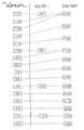
- FIG. 19 is a view illustrating a relationship among the requested sound volume value (Vreq), sound volume value level (L) and amplification factor (Gamp) of the potentiometer.
- the amplification factors “19#”, “23#”, “27#” and “30#” of the potentiometer are allocated to the sound volume adjustment steps “1#” to "4#", respectively, and besides, the requested sound volume values “1#”, “5#” "10#” and “15#” are allocated, respectively.
- the requested sound volume values "0#” to “5#” and the amplification factors “18#” to “23#” are coordinated in a one-by-one coordination relationship.
- the amplification factor includes five steps of "23#” to "27#”. Accordingly, if "5#” is transmitted as the requested sound volume value from the remote controller, then the audio terminal sets the amplification factor to "23#” and sends back "5#” as the actual result sound volume value. Consequently, the remote controller updates the sound volume value pointer to "5#".
- an electronic volume control apparatus which sets an amplification factor (Gamp) of a digital potentiometer in response to a requested sound volume value (Vreq) transmitted thereto from a remote controller and sends back an actual result sound volume value (Vrep) in response to the requested sound volume value is characterized in that such measures as given below are taken.
- the electronic volume control apparatus includes storage means for defining a coordination relationship among M different requested sound volume values (Vreq) and M different actual result sound volume values (Vrep) as well as N different amplification factors (Gamp), means for receiving a requested sound volume value (Vreq), means for searching an amplification factor and an actual result sound volume value coordinated with the received requested sound volume value from within the storage means, means for controlling the potentiometer based on a result of the search of the amplification factor, and responding means for sending back the result of the search of the actual result sound volume value, the storage means including means for coordinating the mth requested sound volume value uniquely with the nth amplification factor and the mth actual result sound volume value and coordinating the [m+i]th requested sound volume value uniquely with the [n+j]th (i > j) amplification factor and the [m+i]th actual result sound volume value, ascending order coordination means for coordinating the amplification factors in an ascending order from the [n+1]th amplification factor with the [
- the electronic volume control apparatus is characterized in that, with the remaining requested sound volume values, an actual result sound volume value having a value different from the requested sound volume value is coordinated.
- the electronic volume control apparatus is characterized in that the ascending order coordination means and the descending order coordination means are data tables wherein the coordination relationships of the requested sound volume values, actual result sound volume values and amplification factors are different from each other.
- the electronic volume control apparatus is characterized in that the storage means is a function whose parameters are a requested sound volume value in the present cycle, a history relating to the requested sound volume values in the preceding cycles and a set value unique to the potentiometer, and the search means determines an actual result sound volume value and an amplification factor to be coordinated with the requested sound volume value based on the function.
- the load of a process for determining an actual result sound volume value and an amplification factor coordinated with a requested sound volume adjustment received from the remote controller can be reduced.
- the memory capacity necessary for determining an actual result sound volume value and an amplification factor coordinated with a requested sound volume adjustment received from the remote controller can be saved.
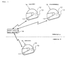
- FIG. 1 is a view showing an example of a form of communication by an intercom to which the present invention is applied.
- a remote controller 14 having a radio relaying function is incorporated in a vehicle A.
- helmets 1a, 1b and 1c which are worn by passengers of the vehicles A and B, a headset including an audio terminal 13 which adopts an electronic volume apparatus of the present invention is mounted together with a microphone 11 and a speaker 12.
- the remote controller 14 and the audio terminals 13 comply with the Bluetooth specifications, and on a piconet in which the remote controller 14 and the audio terminals 13 are accommodated, the remote controller 14 and the audio terminals 13 communicate with each other while the remote controller 14 operates in a master mode and the audio terminals 13 operate in a slave mode.
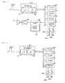
- FIG. 2 is a block diagram showing a configuration of principal part of the audio terminal 13, and description of elements which are not necessary for description of the present invention is omitted herein.
- An antenna AT is connected to a Bluetooth (BT) module.
- a CPU 33 executes various processes in accordance with a program stored in a ROM 34.
- a RAM 35 provides a working area for temporarily storing data and so forth when the CPU 33 executes various processes.
- Various operation switches including a sound volume switch 39 and a display apparatus are connected to an interface 36.
- the sound volume switch 39 includes at least a "+" key 39a and a "-" key 39b.
- An electronic volume apparatus 37 includes a digital potentiometer 371, and amplifies an input signal with an amplification factor in response to operation of the sound volume switch 39 or a requested sound volume value received from the remote controller 14 and outputs the amplified signal to an amplifier 38.
- the BT module includes an RF unit 31 and a BT chip 32 as principal components thereof.
- the BT chip 32 executes a process of establishing intra-piconet synchronism with an opposite party terminal, coding/decoding processes of transmission/reception signals and so forth.
- FIG. 3 is a block diagram showing a configuration of principal part of the remote controller 14, and when compared with the audio terminal 13, the speaker 12, electronic volume apparatus 37 and amplifier 38 are omitted.
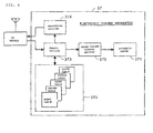
- FIG. 4 is a functional block diagram showing a configuration of principal part of the electronic volume apparatus 37.
- the digital potentiometer 371 sets the amplification factor (Gamp) of the potentiometer 371 in response to a requested sound volume value (Vreq) transmitted from the remote controller 14 and sends back an actual result sound volume value (Vrep) in response to the requested sound volume value.
- Gamp amplification factor
- a coordination relationship among requested sound volume values (Vreq), actual result sound volume values (Vrep) and amplification factors (Gamp) is defined in a coordination relationship storage section 372 such that some of the requested sound volume values are coordinated uniquely with the amplification factors and the actual result sound volume values as hereinafter described in detail.
- a search section 373 searches an amplification factor (Gamp) and an actual result sound volume value (Vrep) coordinated with a requested sound volume value (Vreq) received from the remote controller 14 from within the coordination relationship storage section 372.
- a sound volume control section 375 controls the potentiometer 371 based on a result of the search of the amplification factor.
- a responding section 374 sends back the actual result sound volume value to the remote controller 14.
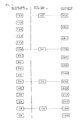
- FIG. 5 is a view illustrating a coordination relationship among requested sound volume values (Vreq) to be transmitted from the remote controller 14, four different proper sound volume levels (L) which can be designated by switch operation of the audio terminal 13 and amplification factors (Gamp) of the digital potentiometer 371 in the present embodiment.
- the four proper sound volume levels (1# to 4#) of the audio terminal 13 are restricted to the four steps of "very small sound volume suitable during stopping", “small sound volume suitable for traveling at a low vehicle speed”, “medium sound volume suitable for traveling at a medium vehicle speed” and “maximum sound volume suitable for traveling at a high vehicle speed”, respectively.
- the amplification factors "19#”, “23#”, “27#” and “30#” are coordinated uniquely with them r, and furthermore, the requested sound volume values (Vreq) "1#”, “5#”, “10#” and “15#” are coordinated uniquely with them.
- the amplification factor Gamp of the digital potentiometer 371 is set to 27#.
- FIG. 6 is a view illustrating an example of a coordination relationship between the requested sound volume values Vreq, amplification factors Gamp and actual result sound volume values Vrep set based on the coordination relationship illustrated in FIG. 5 and registered in the coordination relationship storage section 372 of FIG. 4.
- the coordination relationship is dispersed into five data tables.
- the first table is made a search object where the requested sound volume value Vreq received from the remote controller 14 is equal to or lower than "5#".
- the second and fourth tables are made a search object where the requested sound volume value Vreq ranges from "6#" to "10#”.
- the third and fifth tables are made a search object where the requested sound volume value Vreq is equal to or higher than "11#”.
- step S10 two re-reading flags F10 and F15 hereinafter described are initialized so as to be reset to "0".
- the re-reading flag F10 is used to distinguish which one of the second and fourth tables should be made as an object of search when the requested sound volume value Vreq received from the remote controller 14 is one of "6#" to "10#".
- the re-reading flag F15 is used to distinguish which one of the third and fifth tables should be made as an object of search when the requested sound volume value Vreq received from the remote controller 14 is equal to or higher than "11#”.
- step S11 sound volume value control of controlling the amplification factor of the potentiometer based on the requested sound volume value Vreq received from the remote controller 14 is executed.
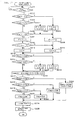
- FIG. 8 is a flow chart illustrating a procedure of the sound volume control, and at step S100, an actual result sound volume value Vrep sent back last to the remote controller 14 is set to a sound volume value pointer Vp.
- FIG. 9 is a view illustrating a relationship between the sound volume value pointer Vp and the re-reading flags F10 and F15 described above in the form of a table.
- step S109 If a requested sound volume value Vreq is transmitted from the remote controller 14 and received at step S109, then at steps S111 and S112, the requested sound volume value Vreq is referred to, and if Vreq ⁇ 5#, then the processing advances to step S115, at which the first table is selected as a search object table. If 5# ⁇ Vreq ⁇ 10#, then the processing advances to step S114, but if 10# ⁇ Vreq, then the processing advances to step S113.
- step S114 the re-reading flag F10 is referred to, and if the re-reading flag F10 is in a reset state, then the processing advances to step S116, at which the second table is selected, but if the re-reading flag F10 is in a set state, then the processing advances to step S117, at which the fourth table is selected.
- step S113 the re-reading flag F15 is referred to, and if the re-reading flag F15 is in a reset state, then the processing advances to step S118, at which the third table is selected, but if the re-reading flag F15 is in a set state, then the processing advances to step S119, at which the fifth table is selected.
- a proper sound volume level L and an amplification factor Gamp coordinated with the requested sound volume value Vreq are read out from the selected table.
- the digital potentiometer 371 is controlled based on the read out amplification factor Gamp.
- the read out actual result sound volume value Vrep is sent back to the remote controller 14.
- step S109 when the sound volume adjustment key of "+" is depressed three times on the remote controller 14, then "8#" higher by three steps than the current value "5#” of the sound volume value pointer Vp is transmitted as a requested sound volume value Vreq from the remote controller 14.
- the processing advances to step S114 through steps S111 and S112.
- step S114 it is decided that the re-reading flag F10 is in a reset state, and consequently, the processing advances to step S116, at which the second table is selected.
- step S120 "26#" and “8#” are read out as the amplification factor Gamp and the actual result sound volume value Vrep coordinated with the requested sound volume value Vreq "8#" in the present cycle from the second table.
- step S121 the digital potentiometer 371 is controlled based on the read out amplification factor "26#”.
- step S122 the read out actual result sound volume value Vrep "8#" is sent back to the remote controller 14.
- the sound volume value pointer Vp is updated from "5#" to "8#" at step S100.
- the sound volume value pointer Vp is updated from "5#" to "8#”.
- step S120 "25#” and “7#” are read out as an amplification factor Gamp and an actual result sound volume value Vrep coordinated with the requested sound volume value Vreq "7#" in the present cycle from the second table.
- the digital potentiometer 371 is controlled based on the read out amplification factor Gamp "25#”.
- the read out actual result sound volume value Vrep "7#” is sent back to the remote controller 14.
- the sound volume value pointer Vp is updated from "8#" to "7#” at step S100.
- the sound volume value pointer Vp is updated from "8#" to "7#”.
- the audio terminal 13 advances its processing through steps S111, S112 and S114 to step S116, at which the second table is selected.
- step S120 "27#" and “10#” are read out as an amplification factor Gamp and an actual result sound volume value Vrep coordinated with the requested sound volume value Vreq "9#” in the present cycle from the second table.
- step S121 the digital potentiometer 371 is controlled based on the read out amplification factor Gamp "27#”.
- step S122 the read out actual result sound volume value Vrep "10#” is sent back to the remote controller 14.
- the sound volume value pointer Vp is updated from "7#" to "10#” at step S100.
- the re-reading flag F15 is reset while the re-reading flag F10 is set.
- the sound volume value pointer Vp is updated from "7#" to "10#”.
- step S117 at which the fourth table is selected.
- step S120 "26#" and “9#” are read out as an amplification factor Gamp and an actual result sound volume value Vrep coordinated with the requested sound volume value Vreq "9#" in the present cycle from the fourth table.
- step S121 the digital potentiometer 371 is controlled based on the read out amplification factor Gamp "26#”.
- step S122 the read out actual result sound volume value Vrep "9#" is sent back to the remote controller 14.
- the sound volume value pointer Vp is updated from "10#" to "9#" at step S100.
- the sound volume value pointer Vp is updated from "10#" to "9#".
- step S120 "24#” and “7#” are read out as an amplification factor Gamp and an actual result sound volume value Vrep coordinated with the requested sound volume value Vreq "7#” in the present cycle from the fourth table.
- step S121 the digital potentiometer 371 is controlled based on the read out amplification factor Gamp "24#”.
- step S122 the read out actual result sound volume value Vrep "7#” is sent back to the remote controller.
- the sound volume value pointer Vp is updated from "9#" to "7#" at step S100.
- the sound volume value pointer Vp is updated from "9#" to "7#".
- step S120 "25#” and “8#” are read out as an amplification factor Gamp and an actual result sound volume value Vrep coordinated with the requested sound volume value Vreq "8#” in the present cycle from the fourth table, respectively.
- step S121 the digital potentiometer 371 is controlled based on the read out amplification factor Gamp "25#”.
- step S122 the read out actual result sound volume value Vrep "8#” is sent back to the remote controller 14.
- the sound volume value pointer Vp is updated from "7#" to "8#” at step S100.
- the sound volume value pointer Vp is updated from "7#" to "8#”. If the sound volume adjustment key of "+" is depressed further three times on the remote controller 14, then "11#" higher by three steps than the current value "8#" of the sound volume value pointer Vp is transmitted as the requested sound volume value Vreq from the remote controller 14.
- step S113 In response to reception of the requested sound volume value Vreq "11#", the audio terminal 13 advances its processing through steps S111 and S112 to step S113.
- step S113 it is decided that the re-reading flag F15 is in a reset state, and consequently, the processing advances to step S118, at which the third table is selected.
- step S120 "28#" and "11#” are read out as an amplification factor Gamp and an actual result sound volume value Vrep coordinated with the requested sound volume value Vreq "11#” in the present cycle from the third table.
- step S121 the digital potentiometer 371 is controlled based on the read out amplification factor Gamp "25#”.
- step S122 the read out actual result sound volume value Vrep "11#" is sent back to the remote controller 14.
- the sound volume value pointer Vp is updated from "8#" to "11#" at step S100.
- the sound volume value pointer Vp is updated from "8#" to "11#".
- step S114 it is decided that the re-reading flag F10 is in a reset state, and consequently, the processing advances to step S117, at which the fourth table is selected.
- step S120 "27#" and “10#” are read out as an amplification factor Gamp and an actual result sound volume value Vrep coordinated with the requested sound volume value Vreq "10#” in the present cycle from the fourth table.
- step S121 the digital potentiometer 371 is controlled based on the read out amplification factor Gamp "27#”.
- step S122 the read out actual result sound volume value Vrep "10#” is sent back to the remote controller 14.
- the sound volume value pointer Vp is updated from "11#" to "10#” at step S100.
- the re-reading flag F15 is reset while the re-reading flag F10 is set.
- the sound volume value pointer Vp is updated from "11#" to "10#”.
- step S113 it is decided that the re-reading flag F15 is in a reset state, and consequently, the processing advances to step S118, at which the third table is selected.
- step S120 "30#” and “15#” are read out as an amplification factor Gamp and an actual result sound volume value Vrep coordinated with the requested sound volume value Vreq "13#” in the present cycle from the third table.
- step S121 the digital potentiometer 371 is controlled based on the read out Gamp "30#”.
- step S122 the read out actual result sound volume value Vrep "15#” is sent back to the remote controller 14.
- the sound volume value pointer Vp is updated from “10#” to "15#” at step S100.
- steps S101 to S108 both of the re-reading flags F15 and F10 are set.
- the sound volume value pointer Vp is updated from "10#" to "15#”.
- step S113 it is decided that the re-reading flag F15 is in a set state, and consequently, the processing advances to step S119, at which the fifth table is selected.
- step S120 "29#" and “14#” are read out as an amplification factor Gamp and an actual result sound volume value Vrep coordinated with the requested sound volume value Vreq "14#” in the present cycle from the fifth table.
- step S121 the digital potentiometer 371 is controlled based on the read out amplification factor Gamp "29#”.
- step S122 the read out actual result sound volume value Vrep "14#" is sent back to the remote controller 14.
- the sound volume value pointer Vp is updated from "15#" to "14#” at step S100.
- the sound volume value pointer Vp is updated from "15#" to "14#”.
- the audio terminal 13 advances its processing through steps S111, S112 and S113 to S119, at which the fifth table is selected.
- steps S111, S112 and S113 are selected.
- step S120 "27#” and “10#” are read out as an amplification factor Gamp and an actual result sound volume value Vrep coordinated with the requested sound volume value Vreq "12#” in the present cycle from the fifth table.
- step S121 the digital potentiometer 371 is controlled based on the read out amplification factor Gamp "27#”.
- the read out actual result sound volume value Vrep "10#” is sent back to the remote controller 14.
- the sound volume value pointer Vp is updated from "14#" to "10#” at step S100.
- the re-reading flag F15 is reset while the re-reading flag F10 is set.
- the sound volume value pointer Vp is updated from "14#" to "10#”.
- step S114 it is decided that the re-reading flag F10 is in a set state, and consequently, the processing advances to step S117, at which the fourth table is selected.
- step S120 "23#” and “5#” are read out as the coordination relationship storage section 372 coordinated with the requested sound volume value Vreq "6#” in the present cycle.
- step S121 the digital potentiometer 371 is controlled based on the read out amplification factor Gamp "23#”.
- step S122 the read out actual result sound volume value Vrep "5#” is sent back to the remote controller 14.
- the sound volume value pointer Vp is updated from “10#” to "5#” at step S100.
- steps S101 to S108 both of the re-reading flags F15 and F10 are reset.
- the sound volume value pointer Vp is updated from "10#" to "5#”.
- step S113 it is decided that the re-reading flag F15 is in a reset state, and consequently, the processing advances to step S118, at which the third table is selected.
- step S120 "28#" and “11#” are read out as an amplification factor Gamp and an actual result sound volume value Vrep coordinated with the requested sound volume value Vreq "11#" in the present cycle from the third table.
- step S121 the digital potentiometer 371 is controlled based on the read out amplification factor Gamp "28#”.
- step S122 the read out actual result sound volume value Vrep "11#" is sent back to the remote controller 14.
- the sound volume value pointer Vp is updated from "5#" to "11#" at step S100.
- the sound volume value pointer Vp is updated from "5#" to "11#”.
- step S114 it is decided that the re-reading flag F10 is in a set state, and consequently, the processing advances to step S117, at which the fourth table is selected.
- step S120 "27#" and “10#” are read out as an amplification factor Gamp and an actual result sound volume value Vrep coordinated with the requested sound volume value Vreq "10#” in the present cycle from the fourth table.
- step S121 the digital potentiometer 371 is controlled based on the read out amplification factor Gamp "27#”.
- step S122 the read out actual result sound volume value Vrep "10#” is sent back to the remote controller 14.
- the sound volume value pointer Vp is updated from "11#" to "10#” at step S100.
- the re-reading flag F15 is reset while the re-reading flag F10 is set.
- the sound volume value pointer Vp is updated from "11#" to "10#”.
- the present embodiment even if the number of steps of sound volume adjustment of the remote controller and the number of steps of sound volume adjustment of the potentiometer are different from each other, sound volume control which is high in fidelity to sound volume operation can be performed, and consequently, sound volume adjustment operation which does not provide an unfamiliar feeling can be anticipated. Further, in the present embodiment, since a coordination relationship among the requested sound volume values, actual result sound volume values and amplification factors is defined in the data tables, the load of a process for determining an actual result sound volume value and an amplification factor coordinated with a requested sound volume adjustment received from the remote controller can be reduced.
- the coordination relationship storage section 372 includes five data tables provided dispersedly, it may otherwise include three data tables provided dispersedly as in a second embodiment whose example is shown in FIG. 14. In this instance, however, it is necessary to modify the procedure of the sound volume value control as illustrated in FIG. 15.
- the present invention is not limited only to this, but the coordination relationship may otherwise be defined based on arithmetic operation of a function as in a third embodiment described below.
- FIGS. 16 and 17 are flow charts illustrating a procedure of the third embodiment wherein an amplification factor Gamp and an actual result sound volume value Vrep to be coordinated with an actual result sound volume value Vrep are determined by arithmetic operation without using a data table
- FIG. 18 is a view schematically illustrating a coordination relationship between the requested sound volume values Vreq and the amplification factors Gamp in the present embodiment.
- step S20 three flags F10, F11 and F15 hereinafter described are initialized so as to be reset to "0".
- step S21 sound volume value control of controlling the amplification factor of the digital potentiometer 371 based on a requested sound volume value Vreq received from the remote controller 14 is executed.
- step S206 it is decided whether or not the received requested sound volume value Vreq is "11#", and if the received requested sound volume value Vreq is "11#", then the flag F11 is set at step S207.
- the re-reading flag F15 is referred to, and if the re-reading flag F15 is in a set state, then the processing advances to step S210, at which "1" is registered into a variable CC. If the flag F15 is in a reset state, then the processing advances to step S211, at which "0" is registered into the variable CC. It is to be noted that, if it is decided at step S206 that the requested sound volume value Vreq is any other than "11#”, then the processing advances to step S208, at which the flag F11 is reset.
- step S224 the digital potentiometer 371 is controlled based on the amplification factor Gamp.
- step S224 the actual result sound volume value Vrep is sent back to the remote controller 14.
- an actual result sound volume value Vrep and an amplification factor Gamp to be coordinated with a requested sound volume value Vreq are determined by arithmetic operation of a function, the memory capacity necessary to determine an actual result sound volume value and an amplification factor coordinated with a requested sound volume value can be saved when compared with those in the first and second embodiments.
Landscapes
- Control Of Amplification And Gain Control (AREA)
- Selective Calling Equipment (AREA)
- Circuit For Audible Band Transducer (AREA)
Abstract
Description
- This invention relates to an electronic volume control apparatus which is remotely controlled by a remote controller, and more particularly to an electronic volume control apparatus which is remotely controlled based on a requested sound.volume value defined according to the standard specifications of the Bluetooth.
- A technique of remotely controlling an electronic volume incorporated in an audio terminal by operating a sound volume adjustment key provided on a remote controller is disclosed in
Patent Document 1. A "+ (plus)" key and a "- (minus)" key are provided as sound volume adjustment keys on the remote controller, and further, a "MUTE" key for attenuating the sound volume to the lowest level at a stroke is sometimes provided on the remote controller. - Meanwhile, specifications for remotely controlling the sound volume of a headset to be mounted on the head by means of a remote controller are set in the Bluetooth which is worldwide communication standards. According to the specifications, 16 steps from "0#" to "15#" are prepared as sound volume adjustment steps.
In sound volume adjustment between a television set and a remote controller therefor, not an instruction of an absolute sound volume value is issued from the remote controller to the television set, but a signal for relatively increasing or decreasing the sound volume at present like "to increase the sound volume by one step" or "to decrease the sound volume by one step" is outputted. In contrast, a remote controller and an audio terminal which comply with the Bluetooth specifications communicate a sound volume value of one of 16 steps therebetween to recognize the sound volume value pointer at present therebetween. Then, if the "+" key is operated once on the remote controller on which the current value of the sound volume value pointer is "8#", then "9#" which is higher by one step than the current value of the sound volume pointer is transmitted as a requested sound volume value from the remote controller to the audio terminal. - The audio terminal side changes the sound volume value from "8#" to "9#" and further updates the sound volume value pointer from "8#" to "9#" in response to reception of the requested sound volume value. Further, a notification of a result of the updating of the sound volume value pointer is issued as an actual result sound volume value to the remote controller. The remote controller updates the sound volume pointer from "8#" to "9#" based on the received actual result sound volume value. Accordingly, if the "+" key is thereafter operated only once on the remote controller side, then a requested sound volume value "10#" is transmitted from the remote controller to the audio terminal.
[Patent Document 1]
Japanese Patent Laid-Open No. Hei 5-308230 - Where an electronic volume of a headset for a driver of a vehicle is remotely controlled by a vehicle body side remote controller, if it is considered to operate the electronic volume of the headset with a hand with a glove put thereon, preferably the number of sound volume adjustment steps is decreased from 16 steps of the standard specifications to make operation of the electronic volume simple and convenient. For example, it is preferable to decrease the number of sound volume adjustment steps, for example, to such four steps as "mute", "small sound volume for stopping", "medium sound volume for traveling at a low or medium speed" and "great sound volume for traveling at a high speed". At this time, in a potentiometer built in the electronic volume, predetermined amplification factors (attenuation factors) are allocated to the four sound volume adjustment steps described above.
- FIG. 19 is a view illustrating a relationship among the requested sound volume value (Vreq), sound volume value level (L) and amplification factor (Gamp) of the potentiometer. The amplification factors "19#", "23#", "27#" and "30#" of the potentiometer are allocated to the sound volume adjustment steps "1#" to "4#", respectively, and besides, the requested sound volume values "1#", "5#" "10#" and "15#" are allocated, respectively.
- At this time, between the sound volume value levels "1#" and "2#", the requested sound volume values "0#" to "5#" and the amplification factors "18#" to "23#" are coordinated in a one-by-one coordination relationship. However, between the sound volume value level "2#" and "3#", while the requested sound volume value includes six steps of "5#" to "10#", the amplification factor includes five steps of "23#" to "27#". Accordingly, if "5#" is transmitted as the requested sound volume value from the remote controller, then the audio terminal sets the amplification factor to "23#" and sends back "5#" as the actual result sound volume value. Consequently, the remote controller updates the sound volume value pointer to "5#".
- If such a sequence of operations as described above is repeated and "9#" is transmitted as the requested sound volume value from the remote controller, then the audio terminal sets the amplification factor to 27# and sends back 9# as the actual result sound volume value. Thus, the remote controller updates the sound volume value pointer to "9#". Accordingly, if the "+" key is operated further on the remote controller, then "10#" is transmitted as the requested sound volume value. However, since "10#" of the requested sound volume value is coordinated with "27#" of the amplification factor, although the "+" key has been operated, the sound volume does not vary.
- It is an object of the present invention to solve the subject of the related art described above and provide an electronic volume control apparatus which can assure good remote controllability.
- In order to attain the object described above, according to the present invention, an electronic volume control apparatus which sets an amplification factor (Gamp) of a digital potentiometer in response to a requested sound volume value (Vreq) transmitted thereto from a remote controller and sends back an actual result sound volume value (Vrep) in response to the requested sound volume value is characterized in that such measures as given below are taken.
- (1) The electronic volume control apparatus includes storage means for defining a coordination relationship among M different requested sound volume values (Vreq) and M different actual result sound volume values (Vrep) as well as N different amplification factors (Gamp), means for receiving a requested sound volume value (Vreq), means for searching an amplification factor and an actual result sound volume value coordinated with the received requested sound volume value from within the storage means, means for controlling the potentiometer based on a result of the search of the amplification factor, and responding means for sending back the result of the search of the actual result sound volume value, the storage means including means for coordinating the mth requested sound volume value uniquely with the nth amplification factor and the mth actual result sound volume value and coordinating the [m+i]th requested sound volume value uniquely with the [n+j]th (i > j) amplification factor and the [m+i]th actual result sound volume value, ascending order coordination means for coordinating the amplification factors in an ascending order from the [n+1]th amplification factor with the [m+1]th to [m+i-1]th requested sound volume values and coordinating the actual result sound volume values in an ascending order from the [m+1]th actual result sound volume value with the [m+1]th to [m+i-1]th requested sound volume values and for uniformly coordinating the [n+j]th amplification factor and the [m+i]th actual result sound volume value with the remaining requested sound volume values, and descending order coordination means for coordinating the amplification factors in a descending order from the [n+j-1]th amplification factor with the [m+i-1]th to [m+1]th requested sound volume values and coordinating the actual result sound volume values in a descending order from the [m+i-1]th actual result sound volume value with the [m+i-1]th to [m+i]th requested sound volume values and for uniformly coordinating the nth amplification factor and the mth actual result sound volume value with the remaining requested sound volume values, the search means being operable to compare, when any of the [m+1]th to [m+i-1]th requested sound volume values (Vreq) is received, a timing at which the mth actual result sound volume value is sent back last and a timing at which the [m+i]th actual result sound volume value is sent back with each other and search the ascending order coordination means if the sending back timing of the mth actual result sound volume value is newer but search the descending order coordination means if the sending back timing of the [m+i]th actual result sound volume value is newer.
- (2) The electronic volume control apparatus is characterized in that, with the remaining requested sound volume values, an actual result sound volume value having a value different from the requested sound volume value is coordinated.
- (3) The electronic volume control apparatus is characterized in that the ascending order coordination means and the descending order coordination means are data tables wherein the coordination relationships of the requested sound volume values, actual result sound volume values and amplification factors are different from each other.
- (4) The electronic volume control apparatus is characterized in that the storage means is a function whose parameters are a requested sound volume value in the present cycle, a history relating to the requested sound volume values in the preceding cycles and a set value unique to the potentiometer, and the search means determines an actual result sound volume value and an amplification factor to be coordinated with the requested sound volume value based on the function.
- According to the present invention, such effects as given below are achieved.
- (1) According to the invention as set forth in
claim 1, even if the number of steps of sound volume adjustment of the remote controller and the number of steps of sound volume adjustment of the potentiometer are different from each other, sound volume adjustment operation which does not provide an unfamiliar feeling can be anticipated. - (2) According to the invention as set forth in
claim 2, even if the number of steps of sound volume adjustment of the remote controller and the number of steps of sound volume adjustment of the potentiometer are different from each other, sound volume control which is accurate for sound volume operation can be anticipated. - (3) According to the invention as set forth in
claim 3, the load of a process for determining an actual result sound volume value and an amplification factor coordinated with a requested sound volume adjustment received from the remote controller can be reduced. - (4) According to the invention as set forth in
claim 4, the memory capacity necessary for determining an actual result sound volume value and an amplification factor coordinated with a requested sound volume adjustment received from the remote controller can be saved. - FIG. 1 is a view showing an example of a communication form by an intercom to which the present invention is applied.
- FIG. 2 is a block diagram showing a configuration of principal part of an audio terminal.
- FIG. 3 is a block diagram showing a configuration of principal part of a remote controller.
- FIG. 4 is a functional block diagram showing a configuration of principal part of an electronic volume apparatus.
- FIG. 5 is a view illustrating a coordination relationship among requested sound volume values Vreq, proper sound volume levels L and amplification factors Gamp.
- FIG. 6 is a view illustrating an example of a relationship among the requested sound volume values Vreq, amplification factors Gamp and an actual result sound volume values Vrep.
- FIG. 7 is a flow chart (part 1) illustrating operation of the present embodiment.
- FIG. 8 is a flow chart (part 2) illustrating operation of the present embodiment.
- FIG. 9 is a view illustrating a relationship among sound volume value pointers Vp and re-reading flags F10 and F15 in the form of a table.
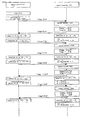
- FIG. 10 is a sequence diagram (part 1) illustrating a procedure of adjustment of the sound volume value when a sound volume adjustment key is operated.
- FIG. 11 is a sequence diagram (part 2) illustrating the procedure of adjustment of the sound volume value when the sound volume adjustment key is operated.
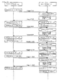
- FIG. 12 is a sequence diagram (part 3) illustrating the procedure of adjustment of the sound volume value when the sound volume adjustment key is operated.
- FIG. 13 is a sequence diagram (part 4) illustrating the procedure of adjustment of the sound volume value when the sound volume adjustment key is operated.
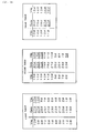
- FIG. 14 is a view showing a structure of data tables of a second embodiment of the present invention.
- FIG. 15 is a flow chart illustrating operation of the second embodiment.
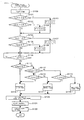
- FIG. 16 is a flow chart (part 1) illustrating operation of a third embodiment of the present invention.
- FIG. 17 is a flow chart (part 2) illustrating operation of the third embodiment of the present invention.
- FIG. 18 is a view showing a structure of data tables of the third embodiment.
- FIG. 19 is a view illustrating a subject of a related art.
- In the following, a preferred embodiment of the present invention is described in detail with reference to the drawings. FIG. 1 is a view showing an example of a form of communication by an intercom to which the present invention is applied. A
remote controller 14 having a radio relaying function is incorporated in a vehicle A. On each ofhelmets audio terminal 13 which adopts an electronic volume apparatus of the present invention is mounted together with amicrophone 11 and aspeaker 12. Theremote controller 14 and theaudio terminals 13 comply with the Bluetooth specifications, and on a piconet in which theremote controller 14 and theaudio terminals 13 are accommodated, theremote controller 14 and theaudio terminals 13 communicate with each other while theremote controller 14 operates in a master mode and theaudio terminals 13 operate in a slave mode. - FIG. 2 is a block diagram showing a configuration of principal part of the
audio terminal 13, and description of elements which are not necessary for description of the present invention is omitted herein. - An antenna AT is connected to a Bluetooth (BT) module. A
CPU 33 executes various processes in accordance with a program stored in aROM 34. ARAM 35 provides a working area for temporarily storing data and so forth when theCPU 33 executes various processes. Various operation switches including asound volume switch 39 and a display apparatus are connected to aninterface 36. Thesound volume switch 39 includes at least a "+" key 39a and a "-" key 39b. Anelectronic volume apparatus 37 includes adigital potentiometer 371, and amplifies an input signal with an amplification factor in response to operation of thesound volume switch 39 or a requested sound volume value received from theremote controller 14 and outputs the amplified signal to anamplifier 38. The BT module includes anRF unit 31 and aBT chip 32 as principal components thereof. TheBT chip 32 executes a process of establishing intra-piconet synchronism with an opposite party terminal, coding/decoding processes of transmission/reception signals and so forth. - FIG. 3 is a block diagram showing a configuration of principal part of the
remote controller 14, and when compared with theaudio terminal 13, thespeaker 12,electronic volume apparatus 37 andamplifier 38 are omitted. - FIG. 4 is a functional block diagram showing a configuration of principal part of the
electronic volume apparatus 37. Thedigital potentiometer 371 sets the amplification factor (Gamp) of thepotentiometer 371 in response to a requested sound volume value (Vreq) transmitted from theremote controller 14 and sends back an actual result sound volume value (Vrep) in response to the requested sound volume value. - A coordination relationship among requested sound volume values (Vreq), actual result sound volume values (Vrep) and amplification factors (Gamp) is defined in a coordination
relationship storage section 372 such that some of the requested sound volume values are coordinated uniquely with the amplification factors and the actual result sound volume values as hereinafter described in detail. Asearch section 373 searches an amplification factor (Gamp) and an actual result sound volume value (Vrep) coordinated with a requested sound volume value (Vreq) received from theremote controller 14 from within the coordinationrelationship storage section 372. A soundvolume control section 375 controls thepotentiometer 371 based on a result of the search of the amplification factor. A respondingsection 374 sends back the actual result sound volume value to theremote controller 14. - FIG. 5 is a view illustrating a coordination relationship among requested sound volume values (Vreq) to be transmitted from the
remote controller 14, four different proper sound volume levels (L) which can be designated by switch operation of theaudio terminal 13 and amplification factors (Gamp) of thedigital potentiometer 371 in the present embodiment. - In the present embodiment, the four proper sound volume levels (1# to 4#) of the
audio terminal 13 are restricted to the four steps of "very small sound volume suitable during stopping", "small sound volume suitable for traveling at a low vehicle speed", "medium sound volume suitable for traveling at a medium vehicle speed" and "maximum sound volume suitable for traveling at a high vehicle speed", respectively. Further, the amplification factors "19#", "23#", "27#" and "30#" are coordinated uniquely with them r, and furthermore, the requested sound volume values (Vreq) "1#", "5#", "10#" and "15#" are coordinated uniquely with them. - In particular, in the present embodiment, if "10#" is transmitted as the requested sound volume value Vreq from the
remote controller 14, or if "3#" is designated as a proper sound volume level L by switch operation of theaudio terminal 13, then the amplification factor Gamp of thedigital potentiometer 371 is set to 27#. - FIG. 6 is a view illustrating an example of a coordination relationship between the requested sound volume values Vreq, amplification factors Gamp and actual result sound volume values Vrep set based on the coordination relationship illustrated in FIG. 5 and registered in the coordination
relationship storage section 372 of FIG. 4. In the present embodiment, the coordination relationship is dispersed into five data tables. - The first table is made a search object where the requested sound volume value Vreq received from the
remote controller 14 is equal to or lower than "5#". The second and fourth tables are made a search object where the requested sound volume value Vreq ranges from "6#" to "10#". The third and fifth tables are made a search object where the requested sound volume value Vreq is equal to or higher than "11#". - Now, operation of the present embodiment is described with reference to flow charts of FIGS. 7 and 8. Referring to FIG. 7, at step S10, two re-reading flags F10 and F15 hereinafter described are initialized so as to be reset to "0". The re-reading flag F10 is used to distinguish which one of the second and fourth tables should be made as an object of search when the requested sound volume value Vreq received from the
remote controller 14 is one of "6#" to "10#". The re-reading flag F15 is used to distinguish which one of the third and fifth tables should be made as an object of search when the requested sound volume value Vreq received from theremote controller 14 is equal to or higher than "11#". At step S11, sound volume value control of controlling the amplification factor of the potentiometer based on the requested sound volume value Vreq received from theremote controller 14 is executed. - FIG. 8 is a flow chart illustrating a procedure of the sound volume control, and at step S100, an actual result sound volume value Vrep sent back last to the
remote controller 14 is set to a sound volume value pointer Vp. At steps S101 and S102, the current value of the sound volume value pointer Vp is referred to, and if Vp = 15#, then the processing advances to step S103, at which the re-reading flag F15 is set (= 1). If the current value of the sound volume value pointer Vp is Vp ≦ 10#, then the processing advances to step S104, at which the re-reading flag F15 is reset (= 0). If the current value of the sound volume value pointer Vp is 10# < Vp < 15#, then the processing advances to step S105 without updating the re-reading flag F15. - At steps S105 and S106, the sound volume value pointer Vp is referred to again, and if Vp ≧ 10#, then the processing advances to step S107, at which the re-reading flag F10 is set. If Vp ≦ 5#, then the processing advances to step S108, at which the re-reading flag F10 is reset. If 5# < Vp < 10#, then the processing advances to step S109 without updating the re-reading flag F10. FIG. 9 is a view illustrating a relationship between the sound volume value pointer Vp and the re-reading flags F10 and F15 described above in the form of a table.
- If a requested sound volume value Vreq is transmitted from the
remote controller 14 and received at step S109, then at steps S111 and S112, the requested sound volume value Vreq is referred to, and if Vreq ≦ 5#, then the processing advances to step S115, at which the first table is selected as a search object table. If 5# < Vreq ≦ 10#, then the processing advances to step S114, but if 10# < Vreq, then the processing advances to step S113. - At step S114, the re-reading flag F10 is referred to, and if the re-reading flag F10 is in a reset state, then the processing advances to step S116, at which the second table is selected, but if the re-reading flag F10 is in a set state, then the processing advances to step S117, at which the fourth table is selected. At step S113, the re-reading flag F15 is referred to, and if the re-reading flag F15 is in a reset state, then the processing advances to step S118, at which the third table is selected, but if the re-reading flag F15 is in a set state, then the processing advances to step S119, at which the fifth table is selected.
- At step S120, a proper sound volume level L and an amplification factor Gamp coordinated with the requested sound volume value Vreq are read out from the selected table. At step S121, the
digital potentiometer 371 is controlled based on the read out amplification factor Gamp. At step S122, the read out actual result sound volume value Vrep is sent back to theremote controller 14. - Now, a procedure of adjusting the sound volume value when the sound volume adjustment key is operated on the
remote controller 14 is described with reference sequence diagrams of FIGS. 10 to 13. Here, description is started from a state wherein the current values of the sound volume value pointer Vp of theremote controller 14 and theaudio terminal 13 are both "5#" and the re-reading flags F15 and F10 of theaudio terminal 13 are both in a reset state (= 0). - As seen in FIG. 10, when the sound volume adjustment key of "+" is depressed three times on the
remote controller 14, then "8#" higher by three steps than the current value "5#" of the sound volume value pointer Vp is transmitted as a requested sound volume value Vreq from theremote controller 14. In theaudio terminal 13, when the requested sound volume value Vreq of "#8" is received at step S109, the processing advances to step S114 through steps S111 and S112. At step S114, it is decided that the re-reading flag F10 is in a reset state, and consequently, the processing advances to step S116, at which the second table is selected. - At step S120, "26#" and "8#" are read out as the amplification factor Gamp and the actual result sound volume value Vrep coordinated with the requested sound volume value Vreq "8#" in the present cycle from the second table. At step S121, the
digital potentiometer 371 is controlled based on the read out amplification factor "26#". At step S122, the read out actual result sound volume value Vrep "8#" is sent back to theremote controller 14. - In the next cycle, the sound volume value pointer Vp is updated from "5#" to "8#" at step S100. At steps S101 to S108, the re-reading flag F15 is reset (= 0) while the re-reading flag F10 maintains the current value (= 0). On the other hand, also in the
remote controller 14 which receives the actual result sound volume value Vrep "8#", the sound volume value pointer Vp is updated from "5#" to "8#". - If the sound volume adjustment key of "-" is depressed further once on the
remote controller 14, then "7#" higher by one step than the current value "8#" of the sound volume value pointer Vp is transmitted as the requested sound volume value Vreq from theremote controller 14. In response to reception of the requested sound volume value Vreq "7#", the audio terminal 13 advances its processing through steps S111, S112 and S114 to step S116, at which the second table is selected. At step S120, "25#" and "7#" are read out as an amplification factor Gamp and an actual result sound volume value Vrep coordinated with the requested sound volume value Vreq "7#" in the present cycle from the second table. At step S121, thedigital potentiometer 371 is controlled based on the read out amplification factor Gamp "25#". At step S122, the read out actual result sound volume value Vrep "7#" is sent back to theremote controller 14. In the next cycle, the sound volume value pointer Vp is updated from "8#" to "7#" at step S100. At steps S101 to S108, the re-reading flag F15 is reset while the re-reading flag F10 maintains it current value (= 0). On the other hand, also in theremote controller 14 which receives the actual result sound volume value Vrep "7#", the sound volume value pointer Vp is updated from "8#" to "7#". - If the sound volume adjustment key of "+" is depressed twice on the
remote controller 14, then "9#" higher by 2 steps than the current value "7#" of the sound volume value pointer Vp is transmitted as the requested sound volume value Vreq from theremote controller 14. In response to reception of the requested sound volume value Vreq "9#", the audio terminal 13 advances its processing through steps S111, S112 and S114 to step S116, at which the second table is selected. - At step S120, "27#" and "10#" are read out as an amplification factor Gamp and an actual result sound volume value Vrep coordinated with the requested sound volume value Vreq "9#" in the present cycle from the second table. At step S121, the
digital potentiometer 371 is controlled based on the read out amplification factor Gamp "27#". At step S122, the read out actual result sound volume value Vrep "10#" is sent back to theremote controller 14. - In the next cycle, the sound volume value pointer Vp is updated from "7#" to "10#" at step S100. At steps S101 to S108, the re-reading flag F15 is reset while the re-reading flag F10 is set. On the other hand, also in the
remote controller 14 which receives the actual result sound volume value Vrep "10#", the sound volume value pointer Vp is updated from "7#" to "10#". - If the sound volume adjustment key of "-" is depressed further once on the
remote controller 14, then "9#" lower by one step than the current value "10#" of the sound volume value pointer Vp is transmitted as the requested sound volume value Vreq from theremote controller 14. In response to reception of the requested sound volume value Vreq "9#", the audio terminal 13 advances its processing through steps S111 and S112 to S114, at which it is decided that the re-reading flag F10 is in a set state. Therefore, the processing advances to step S117, at which the fourth table is selected. - At step S120, "26#" and "9#" are read out as an amplification factor Gamp and an actual result sound volume value Vrep coordinated with the requested sound volume value Vreq "9#" in the present cycle from the fourth table. At step S121, the
digital potentiometer 371 is controlled based on the read out amplification factor Gamp "26#". At step S122, the read out actual result sound volume value Vrep "9#" is sent back to theremote controller 14. - In the next cycle, the sound volume value pointer Vp is updated from "10#" to "9#" at step S100. At steps S101 to S108, the re-reading flag F15 is reset while the re-reading flag F10 maintains its current value (= 1). On the other hand, also in the
remote controller 14 which receives the actual result sound volume value Vrep "9#", the sound volume value pointer Vp is updated from "10#" to "9#". - Referring now to FIG. 11, if the sound volume adjustment key of "-" is depressed further twice on the
remote controller 14, then "7#" lower by two steps than the current value "9#" of the sound volume value pointer Vp is transmitted as the requested sound volume value Vreq from theremote controller 14. In response to reception of the requested sound volume value Vreq "7#", the audio terminal 13 advances its processing through steps S111, S112 and S114 to step S117, at which the fourth table is selected. At step S120, "24#" and "7#" are read out as an amplification factor Gamp and an actual result sound volume value Vrep coordinated with the requested sound volume value Vreq "7#" in the present cycle from the fourth table. At step S121, thedigital potentiometer 371 is controlled based on the read out amplification factor Gamp "24#". At step S122, the read out actual result sound volume value Vrep "7#" is sent back to the remote controller. - In the next cycle, the sound volume value pointer Vp is updated from "9#" to "7#" at step S100. At steps S101 to S108, the re-reading flag F15 is reset while the re-reading flag F10 maintains its current value (= 1). On the other hand, also in the
remote controller 14 which receives the actual result sound volume value Vrep "7#", the sound volume value pointer Vp is updated from "9#" to "7#". - If the sound volume adjustment key of "+" is depressed further once on the
remote controller 14, then "8#" higher by one step than the current value "7#" of the sound volume value pointer Vp is transmitted as the requested sound volume value Vreq from theremote controller 14. In response to reception of the requested sound volume value Vreq "8#", the audio terminal 13 advances its processing through steps S111, S112 and S114 to step S117, at which the fourth table is selected. At step S120, "25#" and "8#" are read out as an amplification factor Gamp and an actual result sound volume value Vrep coordinated with the requested sound volume value Vreq "8#" in the present cycle from the fourth table, respectively. At step S121, thedigital potentiometer 371 is controlled based on the read out amplification factor Gamp "25#". At step S122, the read out actual result sound volume value Vrep "8#" is sent back to theremote controller 14. - In the next cycle, the sound volume value pointer Vp is updated from "7#" to "8#" at step S100. At steps S101 to S108, the re-reading flag F15 is reset while the re-reading flag F10 maintains its current value (= 0). On the other hand, also in the
remote controller 14 which receives the actual result sound volume value Vrep "8#", the sound volume value pointer Vp is updated from "7#" to "8#".
If the sound volume adjustment key of "+" is depressed further three times on theremote controller 14, then "11#" higher by three steps than the current value "8#" of the sound volume value pointer Vp is transmitted as the requested sound volume value Vreq from theremote controller 14. In response to reception of the requested sound volume value Vreq "11#", the audio terminal 13 advances its processing through steps S111 and S112 to step S113. At step S113, it is decided that the re-reading flag F15 is in a reset state, and consequently, the processing advances to step S118, at which the third table is selected. At step S120, "28#" and "11#" are read out as an amplification factor Gamp and an actual result sound volume value Vrep coordinated with the requested sound volume value Vreq "11#" in the present cycle from the third table. At step S121, thedigital potentiometer 371 is controlled based on the read out amplification factor Gamp "25#". At step S122, the read out actual result sound volume value Vrep "11#" is sent back to theremote controller 14. - In the next cycle, the sound volume value pointer Vp is updated from "8#" to "11#" at step S100. At steps S101 to S108, the re-reading flag F15 maintains the current value (= 0) while the re-reading flag F10 is set. On the other hand, also in the
remote controller 14 which receives the actual result sound volume value Vrep "11#", the sound volume value pointer Vp is updated from "8#" to "11#". - If the sound volume adjustment key of "-" is depressed further once on the
remote controller 14, then "10#" lower by one step than the current value "11#" of the sound volume value pointer Vp is transmitted as the requested sound volume value Vreq from theremote controller 14. In response to reception of the requested sound volume value Vreq "10#", the audio terminal 13 advances its processing through steps S111 and S112 to S114. At step S114, it is decided that the re-reading flag F10 is in a reset state, and consequently, the processing advances to step S117, at which the fourth table is selected. At step S120, "27#" and "10#" are read out as an amplification factor Gamp and an actual result sound volume value Vrep coordinated with the requested sound volume value Vreq "10#" in the present cycle from the fourth table. At step S121, thedigital potentiometer 371 is controlled based on the read out amplification factor Gamp "27#". At step S122, the read out actual result sound volume value Vrep "10#" is sent back to theremote controller 14. - In the next cycle, the sound volume value pointer Vp is updated from "11#" to "10#" at step S100. At steps S101 to S108, the re-reading flag F15 is reset while the re-reading flag F10 is set. On the other hand, also in the remote controller which receives the actual result sound volume value Vrep "10#", the sound volume value pointer Vp is updated from "11#" to "10#".
- Referring now to FIG. 12, if the sound volume adjustment key of "+" is depressed further three times on the
remote controller 14, then "13#" higher by three steps than the current value "10#" of the sound volume value pointer Vp is transmitted as the requested sound volume value Vreq from theremote controller 14. In response to reception of the requested sound volume value Vreq "13#", the audio terminal 13 advances its processing through steps S111 and S112 to step S113. At step S113, it is decided that the re-reading flag F15 is in a reset state, and consequently, the processing advances to step S118, at which the third table is selected. At step S120, "30#" and "15#" are read out as an amplification factor Gamp and an actual result sound volume value Vrep coordinated with the requested sound volume value Vreq "13#" in the present cycle from the third table. At step S121, thedigital potentiometer 371 is controlled based on the read out Gamp "30#". At step S122, the read out actual result sound volume value Vrep "15#" is sent back to theremote controller 14. - In the next cycle, the sound volume value pointer Vp is updated from "10#" to "15#" at step S100. At steps S101 to S108, both of the re-reading flags F15 and F10 are set. On the other hand, also in the
remote controller 14 which receives the actual result sound volume value Vrep "15#", the sound volume value pointer Vp is updated from "10#" to "15#". - If the sound volume adjustment key of "-" is depressed further once on the
remote controller 14, then "14#" lower by one step than the current value "15#" of the sound volume value pointer Vp is transmitted as the requested sound volume value Vreq from theremote controller 14. In response to reception of the requested sound volume value Vreq "14#", the audio terminal 13 advances its processing through steps S111 and S112 to S113. At step S113, it is decided that the re-reading flag F15 is in a set state, and consequently, the processing advances to step S119, at which the fifth table is selected. At step S120, "29#" and "14#" are read out as an amplification factor Gamp and an actual result sound volume value Vrep coordinated with the requested sound volume value Vreq "14#" in the present cycle from the fifth table. At step S121, thedigital potentiometer 371 is controlled based on the read out amplification factor Gamp "29#". At step S122, the read out actual result sound volume value Vrep "14#" is sent back to theremote controller 14. - In the next cycle, the sound volume value pointer Vp is updated from "15#" to "14#" at step S100. At steps S101 to S108, the re-reading flag F15 maintains the current value (= 1) while the re-reading flag F10 is set. On the other hand, also in the remote controller which receives the actual result sound volume value Vrep "14#", the sound volume value pointer Vp is updated from "15#" to "14#".
- If the sound volume adjustment key of "-" is depressed further twice on the
remote controller 14, then "12#" lower by two steps than the current value "14#" of the sound volume value pointer Vp is transmitted as the requested sound volume value Vreq from theremote controller 14. In response to reception of the requested sound volume value Vreq "12#", the audio terminal 13 advances its processing through steps S111, S112 and S113 to S119, at which the fifth table is selected. At step S120, "27#" and "10#" are read out as an amplification factor Gamp and an actual result sound volume value Vrep coordinated with the requested sound volume value Vreq "12#" in the present cycle from the fifth table. At step S121, thedigital potentiometer 371 is controlled based on the read out amplification factor Gamp "27#". At step S122, the read out actual result sound volume value Vrep "10#" is sent back to theremote controller 14. - In the next cycle, the sound volume value pointer Vp is updated from "14#" to "10#" at step S100. At steps S101 to S108, the re-reading flag F15 is reset while the re-reading flag F10 is set. On the other hand, also in the remote controller which receives the actual result sound volume value Vrep "14#", the sound volume value pointer Vp is updated from "14#" to "10#".
- If the sound volume adjustment key of "-" is depressed further four times on the
remote controller 14, then "6#" lower by four steps than the current value "10#" of the sound volume value pointer Vp is transmitted as the requested sound volume value Vreq from theremote controller 14. In response to reception of the requested sound volume value Vreq "6#", the audio terminal 13 advances its processing through steps S111 and S112 to S114. At step S114, it is decided that the re-reading flag F10 is in a set state, and consequently, the processing advances to step S117, at which the fourth table is selected. At step S120, "23#" and "5#" are read out as the coordinationrelationship storage section 372 coordinated with the requested sound volume value Vreq "6#" in the present cycle. At step S121, thedigital potentiometer 371 is controlled based on the read out amplification factor Gamp "23#". At step S122, the read out actual result sound volume value Vrep "5#" is sent back to theremote controller 14. - In the next cycle, the sound volume value pointer Vp is updated from "10#" to "5#" at step S100. At steps S101 to S108, both of the re-reading flags F15 and F10 are reset. On the other hand, also in the remote controller which receives the actual result sound volume value Vrep "5#", the sound volume value pointer Vp is updated from "10#" to "5#".
- Referring now to FIG. 13, if the sound volume adjustment key of "+" is depressed further six times on the
remote controller 14, then "11#" higher by six steps than the current value "5#" of the sound volume value pointer Vp is transmitted as the requested sound volume value Vreq from theremote controller 14. In response to reception of the requested sound volume value Vreq "11#", the audio terminal 13 advances its processing through steps S111 and S112 to S113. At step S113, it is decided that the re-reading flag F15 is in a reset state, and consequently, the processing advances to step S118, at which the third table is selected. At step S120, "28#" and "11#" are read out as an amplification factor Gamp and an actual result sound volume value Vrep coordinated with the requested sound volume value Vreq "11#" in the present cycle from the third table. At step S121, thedigital potentiometer 371 is controlled based on the read out amplification factor Gamp "28#". At step S122, the read out actual result sound volume value Vrep "11#" is sent back to theremote controller 14. - In the next cycle, the sound volume value pointer Vp is updated from "5#" to "11#" at step S100. At steps S101 to S108, the re-reading flag F15 maintains the current value (= 0) while the re-reading flag F10 is set. On the other hand, also in the
remote controller 14 which receives the actual result sound volume value Vrep "11#", the sound volume value pointer Vp is updated from "5#" to "11#". - If the sound volume adjustment key of "-" is depressed further once on the
remote controller 14, then "10#" lower by one step than the current value "11#" of the sound volume value pointer Vp is transmitted as the requested sound volume value Vreq from theremote controller 14. In response to reception of the requested sound volume value Vreq "10#", the audio terminal 13 advances its processing through steps S111 and S112 to S114. At step S114, it is decided that the re-reading flag F10 is in a set state, and consequently, the processing advances to step S117, at which the fourth table is selected. At step S120, "27#" and "10#" are read out as an amplification factor Gamp and an actual result sound volume value Vrep coordinated with the requested sound volume value Vreq "10#" in the present cycle from the fourth table. At step S121, thedigital potentiometer 371 is controlled based on the read out amplification factor Gamp "27#". At step S122, the read out actual result sound volume value Vrep "10#" is sent back to theremote controller 14. - In the next cycle, the sound volume value pointer Vp is updated from "11#" to "10#" at step S100. At steps S101 to S108, the re-reading flag F15 is reset while the re-reading flag F10 is set. On the other hand, also in the remote controller which receives the actual result sound volume value Vrep "10#", the sound volume value pointer Vp is updated from "11#" to "10#".
- According to the present embodiment, even if the number of steps of sound volume adjustment of the remote controller and the number of steps of sound volume adjustment of the potentiometer are different from each other, sound volume control which is high in fidelity to sound volume operation can be performed, and consequently, sound volume adjustment operation which does not provide an unfamiliar feeling can be anticipated. Further, in the present embodiment, since a coordination relationship among the requested sound volume values, actual result sound volume values and amplification factors is defined in the data tables, the load of a process for determining an actual result sound volume value and an amplification factor coordinated with a requested sound volume adjustment received from the remote controller can be reduced.
- It is to be noted that, while it is described in the embodiment described above that the coordination
relationship storage section 372 includes five data tables provided dispersedly, it may otherwise include three data tables provided dispersedly as in a second embodiment whose example is shown in FIG. 14. In this instance, however, it is necessary to modify the procedure of the sound volume value control as illustrated in FIG. 15. - Further, while it is described in the embodiments described above that the data tables are utilized to define a coordination relationship among the requested sound volume values Vreq, amplification factors Gamp and actual result sound volume values Vrep, the present invention is not limited only to this, but the coordination relationship may otherwise be defined based on arithmetic operation of a function as in a third embodiment described below.
- FIGS. 16 and 17 are flow charts illustrating a procedure of the third embodiment wherein an amplification factor Gamp and an actual result sound volume value Vrep to be coordinated with an actual result sound volume value Vrep are determined by arithmetic operation without using a data table, and FIG. 18 is a view schematically illustrating a coordination relationship between the requested sound volume values Vreq and the amplification factors Gamp in the present embodiment.
- Referring to FIG. 16, at step S20, three flags F10, F11 and F15 hereinafter described are initialized so as to be reset to "0". At step S21, sound volume value control of controlling the amplification factor of the
digital potentiometer 371 based on a requested sound volume value Vreq received from theremote controller 14 is executed. - FIG. 17 is a flow chart illustrating a procedure of the sound volume value control. If a requested sound volume value Vreq transmitted from the
remote controller 14 is received at step S201, then the requested sound volume value Vreq is referred to at steps S202 and S203. If Vreq = 15#, then the processing advances to step S205, at which the flag F15 is set (= 1) and "2" is registered into a variable CB. If Vreq ≦ 10#, then the processing advances to step S204, at which the flag F15 is reset (= 0) and "0" is registered into the variable CB. If 10# < Vreq < 15#, then the processing advances to step S206 without updating the re-reading flag F15 and the variable CB. - At step S206, it is decided whether or not the received requested sound volume value Vreq is "11#", and if the received requested sound volume value Vreq is "11#", then the flag F11 is set at step S207. At step S209, the re-reading flag F15 is referred to, and if the re-reading flag F15 is in a set state, then the processing advances to step S210, at which "1" is registered into a variable CC. If the flag F15 is in a reset state, then the processing advances to step S211, at which "0" is registered into the variable CC. It is to be noted that, if it is decided at step S206 that the requested sound volume value Vreq is any other than "11#", then the processing advances to step S208, at which the flag F11 is reset.
- At steps S212 and S213, the requested sound volume value Vreq is referred to, and if Vreq ≧ 10#, then the processing advances to step S215, at which the flag F10 is set (= 1) and "1" is registered into a variable CA. If Vrep ≦ 5#, then the processing advances to step S214, at which the flag F10 is reset (= 0) and "0" is registered into the variable CA. If 5 < Vrep < 10#, then the processing advances to step S216 without updating the flag F10 and the variable CA. At step S216, the amplification factor Gamp of the
digital potentiometer 371 is calculated provisionally in accordance with the following expression (1):
- At steps S217, S218 and S219, a result of the calculation of the amplification factor Gamp is referred to. If Gamp ≧ "30#", then the processing advances from step S217 to step S220, at which the amplification factor Gamp is limited to "30#" and the actual result sound volume value Vrep is set to "15#". If Gamp = "27#", then the processing advances from step S218 to step S221, at which the actual result sound volume value Vrep is set to "10#". If Gamp = "23#", then the processing advances from step S219 to step S222, at which the actual result sound volume value Vrep is set to "5#". At step S223, the actual result sound volume value Vrep is registered as it is as the actual result sound volume value Vrep in the present cycle.
- At step S224, the
digital potentiometer 371 is controlled based on the amplification factor Gamp. At step S224, the actual result sound volume value Vrep is sent back to theremote controller 14. - According to the present embodiment, since an actual result sound volume value Vrep and an amplification factor Gamp to be coordinated with a requested sound volume value Vreq are determined by arithmetic operation of a function, the memory capacity necessary to determine an actual result sound volume value and an amplification factor coordinated with a requested sound volume value can be saved when compared with those in the first and second embodiments.
- 1a, 1b, 1c ... helmet, 11 ... microphone, 12 ... speaker, 13 ... audio terminal, 14 --- remote controller, 37 ... electronic volume apparatus, 38 ... amplifier, 371 ... digital potentiometer, 372 ... coordination relationship storage section, 373 ... search section, 374 ... responding section, 375 ··· sound volume control section
Claims (4)
- An electronic volume control apparatus (37) which sets an amplification factor (Gamp) of a digital potentiometer (371) in response to a requested sound volume value (Vreq) transmitted thereto from a remote controller (14) and sends back an actual result sound volume value (Vrep) in response to the requested sound volume value, said electronic volume control apparatus (37) comprising:storage means for defining a coordination relationship among M different requested sound volume values (Vreq) and M different actual result sound volume values (Vrep) as well as N (M ≠ N) different amplification factors (Gamp);means for receiving a requested sound volume value (Vreq) transmitted from said remote controller (14);means for searching an amplification factor and an actual result sound volume value coordinated with the received requested sound volume value from within said storage means;means for controlling said potentiometer (371) based on a result of the search of the amplification factor; andresponding means for sending back the result of the search of the actual result sound volume value;said storage means including:means for coordinating the mth requested sound volume value uniquely with the nth amplification factor and the mth actual result sound volume value and coordinating the [m+i]th requested sound volume value uniquely with the [n+j]th (i > j) amplification factor and the [m+i]th actual result sound volume value;ascending order coordination means for coordinating the amplification factors in an ascending order from the [n+1]th amplification factor with the [m+1]th to [m+i-1]th requested sound volume values and coordinating the actual result sound volume values in an ascending order from the [m+1]th actual result sound volume value with the [m+1]th to [m+i-1]th requested sound volume values and for uniformly coordinating the [n+j]th amplification factor and the [m+i]th actual result sound volume value with the remaining requested sound volume values; anddescending order coordination means for coordinating the amplification factors in a descending order from the [n+j-1]th amplification factor with the [m+i-1]th to [m+1]th requested sound volume values and coordinating the actual result sound volume values in a descending order from the [m+i-1]th actual result sound volume value with the [m+i-1]th to [m+i]th requested sound volume values and for uniformly coordinating the nth amplification factor and the mth actual result sound volume value with the remaining requested sound volume values;said search means being operable to compare, when any of the [m+1]th to [m+i-1]th requested sound volume values (Vreq) is received, a timing at which the mth actual result sound volume value is sent back last and a timing at which the [m+i]th actual result sound volume value is sent back with each other and search said ascending order coordination means if the sending back timing of the mth actual result sound volume value is newer but search said descending order coordination means if the sending back timing of the [m+i]th actual result sound volume value is newer.
- An electronic volume control apparatus (37) according to claim 1, wherein, with the remaining requested sound volume values, an actual result sound volume value having a value different from the requested sound volume value is coordinated.
- An electronic volume control apparatus (37) according to claim 1 or 2, wherein said ascending order coordination means and said descending order coordination means are data tables wherein the coordination relationships (372) of the requested sound volume values, actual result sound volume values and amplification factors are different from each other.
- An electronic volume control apparatus (37) according to claims 1 to 3, wherein said storage means is a function whose parameters are a requested sound volume value in the present cycle, a history relating to the requested sound volume values in the preceding cycles and a set value unique to said potentiometer (371), and said search means determines an actual result sound volume value and an amplification factor to be coordinated with the requested sound volume value based on the function.
Applications Claiming Priority (1)
| Application Number | Priority Date | Filing Date | Title |
|---|---|---|---|
| JP2004284910A JP4480007B2 (en) | 2004-09-29 | 2004-09-29 | Electronic volume control device |
Publications (2)
| Publication Number | Publication Date |
|---|---|
| EP1643638A1 true EP1643638A1 (en) | 2006-04-05 |
| EP1643638B1 EP1643638B1 (en) | 2009-06-24 |
Family
ID=35045132
Family Applications (1)
| Application Number | Title | Priority Date | Filing Date |
|---|---|---|---|
| EP05016318A Expired - Lifetime EP1643638B1 (en) | 2004-09-29 | 2005-07-27 | Electronic volume control apparatus |
Country Status (5)
| Country | Link |
|---|---|
| US (1) | US7929712B2 (en) |
| EP (1) | EP1643638B1 (en) |
| JP (1) | JP4480007B2 (en) |
| DE (1) | DE602005015066D1 (en) |
| TW (1) | TWI298581B (en) |
Families Citing this family (11)
| Publication number | Priority date | Publication date | Assignee | Title |
|---|---|---|---|---|
| JP4688701B2 (en) * | 2006-03-09 | 2011-05-25 | 富士通東芝モバイルコミュニケーションズ株式会社 | Communication terminal |
| GB2448744A (en) * | 2007-04-26 | 2008-10-29 | Wolfson Microelectronics Plc | Look-up table indexing scheme with null values used to expand table to have a power of two number of entries in each cycle of coefficients |
| JP4895921B2 (en) * | 2007-06-08 | 2012-03-14 | パナソニック株式会社 | Audio signal processing system |
| US8107947B1 (en) * | 2009-06-24 | 2012-01-31 | Sprint Spectrum L.P. | Systems and methods for adjusting the volume of a remote push-to-talk device |
| JP2011024046A (en) * | 2009-07-16 | 2011-02-03 | Fujitsu Toshiba Mobile Communications Ltd | Information processing apparatus |
| JP4797215B2 (en) * | 2010-02-26 | 2011-10-19 | オンキヨー株式会社 | Volume control system |
| CN102333142A (en) * | 2011-10-26 | 2012-01-25 | 捷开通讯科技(上海)有限公司 | Volume regulation device and method for mobile terminal |
| JP6186774B2 (en) * | 2013-03-15 | 2017-08-30 | 日本電気株式会社 | Audio reproduction system, audio reproduction apparatus, audio output apparatus, volume control method, and volume control program |
| JP5610025B2 (en) * | 2013-04-16 | 2014-10-22 | ヤマハ株式会社 | Sound processor |
| CN107864280A (en) * | 2017-10-31 | 2018-03-30 | 珠海市魅族科技有限公司 | A kind of indicating mode switching method, device, computer installation and storage medium |
| CN111182099B (en) * | 2019-12-30 | 2021-05-07 | 海信电子科技(深圳)有限公司 | Terminal |
Citations (3)
| Publication number | Priority date | Publication date | Assignee | Title |
|---|---|---|---|---|
| JPH05308230A (en) | 1992-04-28 | 1993-11-19 | Sanyo Electric Co Ltd | Sound volume adjustment device |
| EP1401110A2 (en) * | 2002-09-20 | 2004-03-24 | Honda Giken Kogyo Kabushiki Kaisha | Remote controlled electronic volume controller |
| US20040107442A1 (en) * | 2002-12-03 | 2004-06-03 | Bayley Michael W. | Audio volume control |
Family Cites Families (6)
| Publication number | Priority date | Publication date | Assignee | Title |
|---|---|---|---|---|
| JPH0755451Y2 (en) | 1989-12-27 | 1995-12-20 | トヨタ自動車株式会社 | Inter-vehicle distance detector |
| JP2001169367A (en) | 1999-12-14 | 2001-06-22 | Matsushita Electric Ind Co Ltd | Equipment control system, remote control and controlled equipment |
| JP2002264874A (en) | 2001-03-12 | 2002-09-18 | Toshiba Corp | Communication device for motorcycle, helmet and anti-theft device using this communication device |
| JP3088109U (en) | 2002-02-21 | 2002-08-30 | 船井電機株式会社 | Disc playback device |
| JP3902997B2 (en) | 2002-09-20 | 2007-04-11 | 本田技研工業株式会社 | Electronic volume control device and remote controller thereof |
| JP3902996B2 (en) | 2002-09-20 | 2007-04-11 | 本田技研工業株式会社 | Electronic volume device |
-
2004
- 2004-09-29 JP JP2004284910A patent/JP4480007B2/en not_active Expired - Fee Related
-
2005
- 2005-07-27 TW TW094125486A patent/TWI298581B/en active
- 2005-07-27 DE DE602005015066T patent/DE602005015066D1/en not_active Expired - Lifetime
- 2005-07-27 EP EP05016318A patent/EP1643638B1/en not_active Expired - Lifetime
- 2005-09-14 US US11/224,923 patent/US7929712B2/en not_active Expired - Fee Related
Patent Citations (3)
| Publication number | Priority date | Publication date | Assignee | Title |
|---|---|---|---|---|
| JPH05308230A (en) | 1992-04-28 | 1993-11-19 | Sanyo Electric Co Ltd | Sound volume adjustment device |
| EP1401110A2 (en) * | 2002-09-20 | 2004-03-24 | Honda Giken Kogyo Kabushiki Kaisha | Remote controlled electronic volume controller |
| US20040107442A1 (en) * | 2002-12-03 | 2004-06-03 | Bayley Michael W. | Audio volume control |
Also Published As
| Publication number | Publication date |
|---|---|
| JP4480007B2 (en) | 2010-06-16 |
| US20060067543A1 (en) | 2006-03-30 |
| TWI298581B (en) | 2008-07-01 |
| EP1643638B1 (en) | 2009-06-24 |
| TW200623616A (en) | 2006-07-01 |
| US7929712B2 (en) | 2011-04-19 |
| DE602005015066D1 (en) | 2009-08-06 |
| JP2006101200A (en) | 2006-04-13 |
Similar Documents
| Publication | Publication Date | Title |
|---|---|---|
| EP1643638B1 (en) | Electronic volume control apparatus | |
| CN1108020C (en) | Handheld Cellular Telephones with Power Management Features | |
| US6873837B1 (en) | Emergency reporting system and terminal apparatus therein | |
| JP2004029323A (en) | Speech recognition system, terminal, speech recognition server and computer program | |
| JP2023500146A (en) | Uplink resource determination method, instruction method, terminal and network equipment | |
| US7957774B2 (en) | Hands-free communication system for use in automotive vehicle | |
| US20130053094A1 (en) | Portable electronic device, sound output method, and sound output program | |
| EP0782369A2 (en) | Method and apparatus for controlling the output level of the loudspeakers in a vehicle | |
| US7457424B2 (en) | Electronic volume device and remote controller thereof | |
| JP3902997B2 (en) | Electronic volume control device and remote controller thereof | |
| EP4228190A1 (en) | Transmission parameter determination method and apparatus and terminal device | |
| JP3902996B2 (en) | Electronic volume device | |
| JP3375465B2 (en) | Transmission output control device | |
| US7680519B2 (en) | Handsfree apparatus including volume control | |
| JPH07240783A (en) | Transmission/reception level adjusting device | |
| US5990867A (en) | Wireless input device and wireless input method which automatically reduces transmitted data according to data size | |
| US20250016500A1 (en) | Sound system | |
| US10175929B2 (en) | Interface device for wirelessly controlling an audio device | |
| JPH06237202A (en) | Portable telephone set | |
| JPH06296158A (en) | On-vehicle audio equipment | |
| US7783064B2 (en) | Hearing aid system | |
| KR20240011586A (en) | Electronic device with plurality of antennas and controlling method therefor | |
| KR100369647B1 (en) | Gain controlling methode for analyzing of hand-free function | |
| JP2000078271A (en) | Hands-free telephone set | |
| JPH0631240U (en) | Cordless phone |
Legal Events
| Date | Code | Title | Description |
|---|---|---|---|
| PUAI | Public reference made under article 153(3) epc to a published international application that has entered the european phase |
Free format text: ORIGINAL CODE: 0009012 |
|
| 17P | Request for examination filed |
Effective date: 20050727 |
|
| AK | Designated contracting states |
Kind code of ref document: A1 Designated state(s): AT BE BG CH CY CZ DE DK EE ES FI FR GB GR HU IE IS IT LI LT LU LV MC NL PL PT RO SE SI SK TR |
|
| AX | Request for extension of the european patent |
Extension state: AL BA HR MK YU |
|
| 17Q | First examination report despatched |
Effective date: 20060705 |
|
| AKX | Designation fees paid |
Designated state(s): DE FR GB IT |
|
| 17Q | First examination report despatched |
Effective date: 20060705 |
|
| GRAP | Despatch of communication of intention to grant a patent |
Free format text: ORIGINAL CODE: EPIDOSNIGR1 |
|
| GRAS | Grant fee paid |
Free format text: ORIGINAL CODE: EPIDOSNIGR3 |
|
| GRAA | (expected) grant |
Free format text: ORIGINAL CODE: 0009210 |
|
| AK | Designated contracting states |
Kind code of ref document: B1 Designated state(s): DE FR GB IT |
|
| REG | Reference to a national code |
Ref country code: GB Ref legal event code: FG4D |
|
| REF | Corresponds to: |
Ref document number: 602005015066 Country of ref document: DE Date of ref document: 20090806 Kind code of ref document: P |
|
| PLBE | No opposition filed within time limit |
Free format text: ORIGINAL CODE: 0009261 |
|
| STAA | Information on the status of an ep patent application or granted ep patent |
Free format text: STATUS: NO OPPOSITION FILED WITHIN TIME LIMIT |
|
| 26N | No opposition filed |
Effective date: 20100325 |
|
| PGFP | Annual fee paid to national office [announced via postgrant information from national office to epo] |
Ref country code: FR Payment date: 20100805 Year of fee payment: 6 |
|
| REG | Reference to a national code |
Ref country code: FR Ref legal event code: ST Effective date: 20120330 |
|
| PG25 | Lapsed in a contracting state [announced via postgrant information from national office to epo] |
Ref country code: FR Free format text: LAPSE BECAUSE OF NON-PAYMENT OF DUE FEES Effective date: 20110801 |
|
| PGFP | Annual fee paid to national office [announced via postgrant information from national office to epo] |
Ref country code: GB Payment date: 20130724 Year of fee payment: 9 |
|
| PGFP | Annual fee paid to national office [announced via postgrant information from national office to epo] |
Ref country code: DE Payment date: 20140724 Year of fee payment: 10 |
|
| PGFP | Annual fee paid to national office [announced via postgrant information from national office to epo] |
Ref country code: IT Payment date: 20140718 Year of fee payment: 10 |
|
| GBPC | Gb: european patent ceased through non-payment of renewal fee |
Effective date: 20140727 |
|
| PG25 | Lapsed in a contracting state [announced via postgrant information from national office to epo] |
Ref country code: GB Free format text: LAPSE BECAUSE OF NON-PAYMENT OF DUE FEES Effective date: 20140727 |
|
| REG | Reference to a national code |
Ref country code: DE Ref legal event code: R119 Ref document number: 602005015066 Country of ref document: DE |
|
| PG25 | Lapsed in a contracting state [announced via postgrant information from national office to epo] |
Ref country code: IT Free format text: LAPSE BECAUSE OF NON-PAYMENT OF DUE FEES Effective date: 20150727 Ref country code: DE Free format text: LAPSE BECAUSE OF NON-PAYMENT OF DUE FEES Effective date: 20160202 |