EP1643113A2 - Multiflow jet engine, system and method of operating the same - Google Patents
Multiflow jet engine, system and method of operating the same Download PDFInfo
- Publication number
- EP1643113A2 EP1643113A2 EP05255968A EP05255968A EP1643113A2 EP 1643113 A2 EP1643113 A2 EP 1643113A2 EP 05255968 A EP05255968 A EP 05255968A EP 05255968 A EP05255968 A EP 05255968A EP 1643113 A2 EP1643113 A2 EP 1643113A2
- Authority
- EP
- European Patent Office
- Prior art keywords
- duct
- airflow
- flade
- engine
- fan
- Prior art date
- Legal status (The legal status is an assumption and is not a legal conclusion. Google has not performed a legal analysis and makes no representation as to the accuracy of the status listed.)
- Withdrawn
Links
- 238000000034 method Methods 0.000 title description 6
- 230000005465 channeling Effects 0.000 claims abstract description 24
- 238000011144 upstream manufacturing Methods 0.000 claims abstract description 15
- 230000001965 increasing effect Effects 0.000 description 10
- 238000001816 cooling Methods 0.000 description 7
- 239000000446 fuel Substances 0.000 description 5
- 230000008878 coupling Effects 0.000 description 2
- 238000010168 coupling process Methods 0.000 description 2
- 238000005859 coupling reaction Methods 0.000 description 2
- 238000003466 welding Methods 0.000 description 2
- 230000000712 assembly Effects 0.000 description 1
- 238000000429 assembly Methods 0.000 description 1
- 238000002485 combustion reaction Methods 0.000 description 1
- 230000003247 decreasing effect Effects 0.000 description 1
- 230000001939 inductive effect Effects 0.000 description 1
- 230000008646 thermal stress Effects 0.000 description 1
Images

Classifications
-
- F—MECHANICAL ENGINEERING; LIGHTING; HEATING; WEAPONS; BLASTING
- F02—COMBUSTION ENGINES; HOT-GAS OR COMBUSTION-PRODUCT ENGINE PLANTS
- F02C—GAS-TURBINE PLANTS; AIR INTAKES FOR JET-PROPULSION PLANTS; CONTROLLING FUEL SUPPLY IN AIR-BREATHING JET-PROPULSION PLANTS
- F02C7/00—Features, components parts, details or accessories, not provided for in, or of interest apart form groups F02C1/00 - F02C6/00; Air intakes for jet-propulsion plants
- F02C7/04—Air intakes for gas-turbine plants or jet-propulsion plants
- F02C7/042—Air intakes for gas-turbine plants or jet-propulsion plants having variable geometry
-
- F—MECHANICAL ENGINEERING; LIGHTING; HEATING; WEAPONS; BLASTING
- F02—COMBUSTION ENGINES; HOT-GAS OR COMBUSTION-PRODUCT ENGINE PLANTS
- F02K—JET-PROPULSION PLANTS
- F02K7/00—Plants in which the working fluid is used in a jet only, i.e. the plants not having a turbine or other engine driving a compressor or a ducted fan; Control thereof
- F02K7/10—Plants in which the working fluid is used in a jet only, i.e. the plants not having a turbine or other engine driving a compressor or a ducted fan; Control thereof characterised by having ram-action compression, i.e. aero-thermo-dynamic-ducts or ram-jet engines
- F02K7/16—Composite ram-jet/turbo-jet engines
-
- F—MECHANICAL ENGINEERING; LIGHTING; HEATING; WEAPONS; BLASTING
- F05—INDEXING SCHEMES RELATING TO ENGINES OR PUMPS IN VARIOUS SUBCLASSES OF CLASSES F01-F04
- F05D—INDEXING SCHEME FOR ASPECTS RELATING TO NON-POSITIVE-DISPLACEMENT MACHINES OR ENGINES, GAS-TURBINES OR JET-PROPULSION PLANTS
- F05D2220/00—Application
- F05D2220/10—Application in ram-jet engines or ram-jet driven vehicles
Definitions
- This invention relates generally to gas turbine engines and more particularly, to methods and apparatus for assembling fladed engines.
- Variable cycle engines are conventionally known for powering high performance aircraft from subsonic to supersonic speeds while attempting to obtain countervailing objectives such as high specific thrust and low fuel consumption.
- ideal aircraft jet engines attempt to operate through various modes of thrust and speed requirements while minimizing fuel consumption.
- variable cycle engines are generally operable over a range of operating conditions.
- conventional variable cycle combined turbojet or turbofan and ramjet engines generally attempt to provide for a range of operation from low subsonic Mach numbers to high supersonic Mach numbers of about Mach 6.
- turbofan-ramjet engines are relatively complex and generally include varying disadvantages.
- at least one known turbofan-ramjet engine includes a ram burner which is wrapped around a core engine, thus creating an undesirably large diameter engine.
- Other known variable cycle engines include variable coannular exhaust nozzles that are relatively complex and difficult to schedule the flow area thereof.
- variable cycle engines include coannular, separate flow paths including a coannular inlet which creates an undesirably large inlet and which typically requires an inlet diverter valve for selectively channeling inlet air flow.
- Other known engines may include one or more of such undesirable structures, thus resulting in an engine that is relatively complex, heavy, large, and inefficient.
- a method for operating a gas turbine engine.
- the method includes providing a core engine, an inner fan assembly, and a fladed fan assembly, coupling a plurality of airflow ducts to the engine including an inner fan duct for channeling airflow through the inner fan assembly, a core engine duct for channeling airflow through the core engine, a bypass fan duct for channeling the airflow around the core engine duct, a flade duct for channeling airflow through the fladed fan assembly, and a ram duct surrounding an upstream portion of the flade duct, and coupling a plurality of control valves to the engine to control an amount of airflow channeled through each of the ducts using the plurality of control valves.
- an airflow system for a gas turbine engine, wherein the gas turbine engine includes a core engine, an inner fan assembly, and a fladed fan assembly.
- the airflow system includes a plurality of airflow ducts for channeling airflow through the engine, wherein the airflow ducts include an inner fan duct for channeling airflow through the inner fan assembly, a core engine duct positioned downstream of and in flow communication with the inner fan duct, wherein the core engine duct is for channeling airflow through the core engine, a bypass fan duct positioned downstream of and in flow communication with the inner fan duct, wherein the bypass fan duct is for channeling the airflow around the core engine duct, a flade duct surrounding the inner fan duct and the bypass fan duct, wherein the flade duct is for channeling airflow through the fladed fan assembly, and a ram duct surrounding an upstream portion of the flade duct.
- the airflow system also includes a plurality of control valves for controlling the airflow through
- a gas turbine engine in a further aspect, includes a core engine that includes an inner fan duct for channeling airflow through a portion of the core engine, and at least one inner fan section including a plurality of fan blades coupled in flow communication with the inner fan duct.
- the engine also includes a flade system including a flade duct surrounding the core engine and including at least one fladed fan coupled in flow communication with the flade duct, wherein the fladed fan includes a plurality of fladed fan blades radially outward of, and coupled to, the inner fan section such that the fladed fan blades are driven by the inner fan section.
- the engine also includes a ram duct system including a ram duct surrounding a portion of the flade system, and a plurality of mode selector valves for controlling airflow between the ram jet and at least one of the flade duct and the inner fan duct.
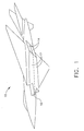
- FIG. 1 is a schematic illustration of a jet aircraft 10 including a plurality of engines 12 and a plurality of nozzle assemblies 14.
- Aircraft 10 includes an aircraft inlet 16 for channeling airflow to engines 12.
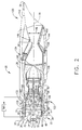
- FIG 2 is a schematic illustration of an exemplary "fan-on-blade" or fladed engine 12 in one mode of operation.
- Figure 3 is a schematic illustration of fladed engine 12 in another mode of operation.
- engine 12 includes a core engine 20 downstream of a fan assembly 22, a flade system 24 radially outward of core engine 20 and fan assembly 22, and a ram duct system 26 disposed radially outward a portion of flade system 24.
- An engine casing 28 surrounds the engine components and is disposed concentrically about an axially oriented engine centerline axis 30.
- Engine 12 includes a plurality of airflow ducts through which airflow 32 from the airflow inlet 16 is channeled.
- engine 12 includes an inner fan duct 34 extending downstream from an inner fan inlet 36 and disposed concentrically around fan assembly 22.
- Inner fan duct 34 is defined between a fan casing 38 and an inner conical hub 40.
- engine inlet airflow 32 enters inner fan duct 34 and is channeled through fan assembly 22 and core engine 20, specifically, through inner fan duct 34 and a core engine duct 41.
- a portion of the airflow channeled through fan assembly 22 bypasses core engine 20 and is exhausted downstream of core engine 20.
- the bypassed airflow is channeled through a bypass duct 42.
- Engine 12 also includes a flade duct 44 extending downstream from a flade inlet 46 and disposed concentrically around inner fan duct 34. Flade inlet 46 facilitates capturing additional airflow 32 that would otherwise spill around engine 12 leading to spillage drag losses on engine 12. Flade duct 44 is defined between fan casing 38 and a radially outer flade casing 48. In the exemplary embodiment, flade duct 44 extends between an upstream end 50, positioned proximate to a front end 52 of engine 12, and a downstream end 54, positioned proximate the exhaust area, or the common A9 expansion area, at a rear end 56 of engine 12. Flade stream air not exiting through this exhaust area will exit through cooling slots (not shown) located in other parts of rear end 56.
- a portion of total engine flow 32 captured by flade inlet 46 is channeled through engine 12 to improve engine 12 performance by increasing thrust through additional exhaust flow.
- airflow 32 captured by flade inlet 46 is channeled by flade duct 44 to facilitate cooling portions of engine 12.
- Engine 12 also includes a ram duct 60 extending downstream from a ram inlet 62 and disposed concentrically around an upstream portion of flade duct 44.
- Ram inlet 62 facilitates capturing additional airflow 32 that would otherwise spill around engine 12 leading to spillage drag losses on engine 12.
- ram inlet 62 facilitates providing airflow to power engine 12 when engine 12 is operating in a high performance mode, such as, for example, when engine 12 is operating at speeds greater than approximately Mach 4.0.
- Ram duct 60 is defined between flade casing 48 and a radially outer ram casing 64.
- ram duct 60 extends axially from engine front end 52 to a position downstream and radially outward of fan assembly 22.
- airflow 32 captured by ram inlet 62 is channeled through engine 12 during certain modes of engine operation to improve engine 12 performance by providing thrust to engine 12. Moreover, airflow 32 captured by ram inlet 62 is channeled by ram duct 44 to facilitate cooling portions of engine 12.
- Fan assembly 22 includes a plurality of fan blades 70.
- Each fan blade 70 includes a leading edge and a trailing edge and extends radially between a root and a tip.
- fan blades 70 are arranged in a two-stage configuration such that fan assembly 22 includes a first fan stage 72 having a first row of circumferentially-spaced fan blades 70, and a second fan stage 74 having a second row of circumferentially-spaced fan blades 70.
- fan assembly 22 includes more or less than two fan stages and includes more or less than two rows of fan blades 70.
- a shroud 80 extends circumferentially around, and is coupled to, each fan blade tip within second fan stage 74.
- shroud 80 is a single annular member that is coupled to each fan blade tip within second stage 74.
- fan assembly 22 includes a plurality of tip shrouded airfoils such that shroud 80 includes a plurality of arcuate members each coupled to at least one fan blade tip such that the arcuate members extend circumferentially around second stage 74.
- Shroud 80 facilitates preventing airflow from flowing between inner fan duct 34 and flade duct 44, or vice-versa.
- shroud 80 is coupled to another stage, such as, for example, first stage 72.
- fan assembly 22 is a counter rotating fan assembly such that first stage 72 is rotatably coupled to, and driven by, a first shaft 82, and second stage 74 is rotatably coupled to, and driven by, a second shaft 84.
- First and second shafts 82 and 84 operate independently with respect to each other, such that first shaft 82 operates with a first rotational speed that is different than a second rotational speed of second shaft 84. Accordingly, first stage 72 and second stage 74 have different operational speeds.
- second shaft 84 rotates in an opposite direction than first shaft 82.
- first and second shafts 82 and 84 operate in the same rotational direction.
- airflow 32 enters inner fan inlet 36 and is channeled through inner fan duct 34. Specifically, airflow 32 is channeled as a fan stream 90 through a plurality of inlet guide vanes 92 towards first stage 72 between fan casing 38 and hub 40. As fan stream 90 is channeled through the first row of fan blades 70, the density of fan stream 90 is increased. Fan stream 90 is then channeled through the second row of fan blades 70 wherein the density of fan stream 90 is further increased. Once fan stream 90 is channeled through fan assembly 22, the airflow is divided by a splitter 94 into a core engine stream 96 and a bypass stream 98.
- splitter 94 is oriented downstream of fan assembly 22 to facilitate dividing fan stream 90 to enable engine to meet engine overall performance requirements relating to thrust and airflow pressure ratios.
- Core engine stream 96 is channeled through core engine 20. Specifically, core engine stream is channeled through a compressor 100, a combustor 102, a high pressure turbine 104, and a low pressure turbine 106.
- bypass duct 42 includes a forward bypass duct 110, an intermediate bypass duct 112, and an aft bypass duct 114.
- Forward bypass duct is positioned between splitter 94 and fan casing 38
- intermediate bypass duct is positioned between splitter 94 and a core engine liner 116
- aft bypass duct is positioned downstream of forward and intermediate bypass ducts 110 and 112 and extends between core engine 22 and fan casing 38.
- intermediate bypass duct 112 channels a portion of core engine stream 96 to bypass duct 42.
- Bypass ducts 110, 112 and 114 are in flow communication with one another when engine 12 is operating in the normal mode. Additionally, the airflow through bypass duct 42 and the core engine stream 96 are burned in the engine afterburner (not shown) before being exhausted from engine 12 through an exhaust nozzle assembly 120.
- fan assembly 22 also includes a fladed fan assembly 122 that includes a plurality of fladed rotor blades 124 positioned within flade duct 44.
- Each fladed blade 124 includes a leading edge and a trailing edge and extends radially between a root and a tip.
- fladed blades 124 are arranged in a row that extends circumferentially around shroud 80. Fladed blades 124 produce a flade stream 126 of airflow that is channeled through flade duct 44.
- Each fladed blade 124 is drivenly coupled to shroud 80 at the blade root and extends radially outward from shroud 80.
- each fladed blade 124 is coupled to shroud 80 via, for example, a welding process, such as, but not limited to, an inductive welding process.
- fladed blades 124 are unitarily formed with shroud 80.
- Fladed blades 124 have a radial height, extending between blade root and blade tip, that is selected to facilitate improving an efficiency potential of flade stream 126, while reducing the risk of exceeding tip speed constraints.
- a row of circumferentially spaced variable area inlet guide vanes 130 are positioned within flade duct 44 upstream of fladed blades 124.
- Inlet guide vanes 130 are operable to channel airflow 32 towards fladed blades 124 and meter the volume of airflow 32 entering flade stream 126.
- Airflow discharged from fladed blades 124 passes through a row of circumferentially spaced outlet guide vanes 132 which change the direction of the airflow to facilitate reducing the rotary velocity component of the airflow.
- flade stream 126 is then channeled downstream through flade duct 44 prior to being exhausted through exhaust nozzle assembly 120. Accordingly, flade stream 126 increases an amount of high pressure airflow available, thus facilitating increasing the overall performance and/or thrust of engine 12.
- flade system 24 also includes a flade stream augmentor 134 to facilitate increasing the thrust output, and therefore the overall performance of engine 12.
- Augmentor 134 is positioned in flade duct 44 such that a portion of flade stream 126 is mixed with a fuel, ignited and then exhausted downstream of augmentor 134 into the exhaust area, or the common A9 expansion area, at flade duct downstream end 54.
- Flade system 24 also includes a flade duct scroll 136 that channels a portion of flade stream 126 from a lower flade section 138 to an upper flade section 140.
- a portion of flade duct 44 continues downstream from flade duct scroll 136 such that flade stream 126 in that portion facilitates cooling fan casing 38 and/or exhaust nozzle assembly 120 proximate engine rear end 56.
- approximately 20%- 30% of flade stream126 continues downstream of flade duct scroll 136 in the corresponding flade duct 44.
- more or less of flade stream 126 continues downstream of flade duct scroll 136 to facilitate improving the cooling efficiency of flade duct 44.
- flade duct scroll 136 extends to upper flade section 140 and is positioned upstream of augmentor 134. Specifically, flade duct scroll 136 channels flade stream 126 upstream of augmentor 134 to facilitate increasing the amount of flade stream airflow that enters augmentor 134 for combustion. As such, the overall thrust potential of engine 12 is increased.
- nozzle assembly 120 includes an upper nozzle section 142 and a lower nozzle section 144.
- Exhaust area 146 is defined by the inner surface of a nozzle liner 148 between the upper and lower nozzle sections 142 and 144, respectively.
- a front flap 150 and a rear flap 152 are coupled to lower nozzle section 144 and are moveable such that throat area 146 is variable. Specifically, throat area 146 is increased and/or decreased depending on the mode of operation and/or the required thrust output of engine 12.
- engine 12 includes a plurality of control valves for controlling an amount of airflow channeled through each of the airflow ducts.
- engine 12 includes an inner mode selector valve 160 and an outer mode selector valve 162 each of which are variably positionable between a fully open position, as illustrated in Figure 2, and a fully closed position, as illustrated in Figure 3.
- inner mode selector valve 160 defines a portion of fan casing 38
- outer mode selector valve 162 defines a portion of flade casing 48.
- mode selector valves 160 and 162 restrict airflow in ram duct 60.
- mode selector valves 160 and 162 define a flow path of the airflow in ram duct 60 and restrict airflow through fan duct 34 and flade duct 44.
- Inner modes selector valve 160 is positioned radially outward of a portion of forward bypass duct 110.
- forward bypass duct 110 is opened, and airflow is channeled through forward bypass duct 110 between inner fan duct 34 and aft bypass duct 114.
- forward bypass duct 110 is closed, and airflow is restricted from being channeled through forward bypass duct 110 between inner fan duct 34 and aft bypass duct 114.
- an inner ram opening 164 is formed in fan casing 38 such that airflow is channeled through inner ram opening 164 between ram duct 60 and aft bypass duct 114.
- Outer modes selector valve 162 is positioned radially outward of a inner mode selector valve 160.
- flade duct 44 When outer mode selector valve 162 is positioned in the open position, flade duct 44 is opened, and airflow is channeled through flade duct 44 between upstream and downstream ends 50 and 54, respectively.
- flade duct 110 When outer mode selector valve 162 is positioned in the closed position, flade duct 110 is closed, and airflow is restricted from being channeled between upstream and downstream ends 50 and 54.
- an outer ram opening 166 is formed in flade casing 48 such that airflow is channeled through outer ram opening 166 between ram duct 60 and the downstream portion of flade duct 44.
- Inner and outer mode selector valves 160 and 162 are selectively positionable in intermediate positions to allow a portion of the airflow in ram duct 60 to be channeled into both flade and aft bypass ducts 44 and 114, respectively. The airflow is then channeled through the flade and aft bypass ducts 44 and 114 into the exhaust nozzle assembly 120 to power the aircraft. In one embodiment, the airflow is channeled to a ram burner, such as augmentor 134, for conventional ramjet operation. In the exemplary embodiment, inner and outer mode selector valves 160 and 162 are controlled by a control system (not shown) for operating valves 160 and 162 in accordance with engine 12 overall performance and output requirements.
- engine 12 also includes a front closure system 170 and a rear closure system 172 each of which are variably positionable between a fully open position, as illustrated in Figure 2, and a fully closed position, as illustrated in Figure 3.
- Closure systems 170 and 172 control an amount of airflow entering and/or exiting fan assembly 22 and core engine 20 and are operated by a control system (not shown) similar to that used by valves 160 and 162. Specifically, as less airflow is required to be channeled through fan assembly 22 and/or core engine 20, closure systems 170 and/or 172 are transferred from the open position to the closed position.
- systems 170 and/or172 are in the open position when engine 12 is operating in a normal mode of operation, such as, for example, at flight speeds approaching approximately Mach 3.0.
- closure systems 170 and/or 172 are in the closed position when engine 12 is operating in a high performance mode of operation, such as, for example, at flight speeds greater than approximately Mach 4.0.
- closure systems 170 and/or 172 are operable in an intermediate position in accordance with engine 12 overall performance and output requirements.
- Front closure system 170 includes a plurality of closing flaps 174 positioned at engine front end 52.
- closing flaps 174 are coupled to engine adjacent engine centerline axis 30 and are rotatable such that a tip 176 of each closure flap 174 abuts against flade casing 48 when closure flaps 174 are in the fully closed position. Accordingly, in the closed position, a minimal amount of airflow is channeled into fan duct 34 and flade duct 44, core engine 20 is shut down, thereby reducing an amount of fuel consumption, and engine 12 is in a ramjet operation, wherein engine is powered by the exhaust produced by the airflow entering ram duct 60. However, in the ramjet mode of operation, a high amount of thermal stress is placed on the internal components of engine 12, specifically, on fan assembly 22 and core engine 20. Accordingly, in the exemplary embodiment, engine 12 includes a thermal management system 180.
- Thermal management system 180 includes an auxiliary duct 182 in flow communication with, and receiving airflow from, ram duct 60, and a heat exchanger 184, such as, for example, a fuel air heat exchanger, for cooling the airflow in auxiliary duct 182.
- Auxiliary duct 182 includes a thermal management system valve 186 for controlling an amount of airflow entering auxiliary duct 182 from ram duct 60.
- Auxiliary duct 182 channels airflow from ram duct 60 to the upstream end of inner fan duct 34 and/or flade duct 44 for cooling the components contained therein.
- thermal management system 180 is operated when front closure system 170 is in the closed position, and/or when a reduced amount of airflow is channeled through inner fan duct 34 and flade duct 44.
- the above-described fladed engines are cost-effective and highly reliable.
- the fladed engine includes a core engine, a fan assembly, a flade system and a ramjet system for increasing the overall performance and reducing the operating cost of the engine.
- the flade system includes a flade duct for capturing a portion of the airflow spilled around the fan inlet and increasing the amount of thrust generated by the engine.
- the engine includes a ram duct for capturing airflow spilled around the flade duct and for operating the engine as a ramjet at high flight speeds.
- a plurality of control valves are provided for controlling the amount of airflow through each of the systems. As a result, the engine operates in multiple flight conditions and at multiple flight speeds.
- fladed engines are described above in detail.
- the fladed engines are not limited to the specific embodiments described herein, but rather, components of each fladed engine may be utilized independently and separately from other components described herein.
- each fladed engine component can also be used in combination with other fladed engine components described herein.
Landscapes
- Engineering & Computer Science (AREA)
- Chemical & Material Sciences (AREA)
- Combustion & Propulsion (AREA)
- Mechanical Engineering (AREA)
- General Engineering & Computer Science (AREA)
- Physics & Mathematics (AREA)
- Geometry (AREA)
- Structures Of Non-Positive Displacement Pumps (AREA)
Abstract
An airflow system for a gas turbine engine is provided, wherein the gas turbine engine includes a core engine (20), an inner fan assembly (22), and a fladed fan assembly (24). The airflow system includes a plurality of airflow ducts for channeling airflow through the engine, wherein the airflow ducts include an inner fan duct (34) for channeling airflow through the inner fan assembly, a core engine duct (41) positioned downstream of, and in flow communication with, the inner fan duct, wherein the core engine duct facilitates channeling airflow through the core engine, a bypass fan duct (42) positioned downstream of, and in flow communication with, the inner fan duct, wherein the bypass fan duct facilitates channeling the airflow around the core engine duct, a flade duct (44) surrounding the inner fan duct and the bypass fan duct, wherein the flade duct facilitates channeling airflow through the fladed fan assembly, and a ram duct (60) surrounding an upstream portion (50) of the flade duct. The airflow system also includes a plurality of control valves (160, 162) for controlling the airflow through the engine.
Description
- This invention relates generally to gas turbine engines and more particularly, to methods and apparatus for assembling fladed engines.
- Variable cycle engines are conventionally known for powering high performance aircraft from subsonic to supersonic speeds while attempting to obtain countervailing objectives such as high specific thrust and low fuel consumption. In other words, ideal aircraft jet engines attempt to operate through various modes of thrust and speed requirements while minimizing fuel consumption.
- In reality however, such an ideal aircraft jet engine must necessarily include many compromises. For example, known high bypass ratio turbofan engines are utilized at subsonic speeds, known low bypass ratio turbofan engines or turbojet engine are used at up to moderate supersonic speeds, and known ramjet engines are utilized at high supersonic speeds. Because these three conventional engines are structurally and functionally different, the three types of engines are typically not optimally operable in multiple speed ranges.
- In contrast, known variable cycle engines are generally operable over a range of operating conditions. In particular, conventional variable cycle combined turbojet or turbofan and ramjet engines generally attempt to provide for a range of operation from low subsonic Mach numbers to high supersonic Mach numbers of about Mach 6. However such turbofan-ramjet engines are relatively complex and generally include varying disadvantages. For example, at least one known turbofan-ramjet engine includes a ram burner which is wrapped around a core engine, thus creating an undesirably large diameter engine. Other known variable cycle engines include variable coannular exhaust nozzles that are relatively complex and difficult to schedule the flow area thereof. Moreover, other known variable cycle engines include coannular, separate flow paths including a coannular inlet which creates an undesirably large inlet and which typically requires an inlet diverter valve for selectively channeling inlet air flow. Other known engines may include one or more of such undesirable structures, thus resulting in an engine that is relatively complex, heavy, large, and inefficient.
- In one aspect of the present invention, a method is provided for operating a gas turbine engine. The method includes providing a core engine, an inner fan assembly, and a fladed fan assembly, coupling a plurality of airflow ducts to the engine including an inner fan duct for channeling airflow through the inner fan assembly, a core engine duct for channeling airflow through the core engine, a bypass fan duct for channeling the airflow around the core engine duct, a flade duct for channeling airflow through the fladed fan assembly, and a ram duct surrounding an upstream portion of the flade duct, and coupling a plurality of control valves to the engine to control an amount of airflow channeled through each of the ducts using the plurality of control valves.
- In another aspect of the invention, an airflow system is provided for a gas turbine engine, wherein the gas turbine engine includes a core engine, an inner fan assembly, and a fladed fan assembly. The airflow system includes a plurality of airflow ducts for channeling airflow through the engine, wherein the airflow ducts include an inner fan duct for channeling airflow through the inner fan assembly, a core engine duct positioned downstream of and in flow communication with the inner fan duct, wherein the core engine duct is for channeling airflow through the core engine, a bypass fan duct positioned downstream of and in flow communication with the inner fan duct, wherein the bypass fan duct is for channeling the airflow around the core engine duct, a flade duct surrounding the inner fan duct and the bypass fan duct, wherein the flade duct is for channeling airflow through the fladed fan assembly, and a ram duct surrounding an upstream portion of the flade duct. The airflow system also includes a plurality of control valves for controlling the airflow through the engine.
- In a further aspect, a gas turbine engine is provided. The gas turbine engine includes a core engine that includes an inner fan duct for channeling airflow through a portion of the core engine, and at least one inner fan section including a plurality of fan blades coupled in flow communication with the inner fan duct. The engine also includes a flade system including a flade duct surrounding the core engine and including at least one fladed fan coupled in flow communication with the flade duct, wherein the fladed fan includes a plurality of fladed fan blades radially outward of, and coupled to, the inner fan section such that the fladed fan blades are driven by the inner fan section. The engine also includes a ram duct system including a ram duct surrounding a portion of the flade system, and a plurality of mode selector valves for controlling airflow between the ram jet and at least one of the flade duct and the inner fan duct.
- Embodiments of the invention will now be described, by way of example, with reference to the accompanying drawings, in which:
- Figure 1 is an end view of an aircraft including an exemplary engine.
- Figure 2 is a schematic illustration of an exemplary fladed engine that may be used with the aircraft shown in Figure 1 having mode selector valves in an open position;
- Figure 3 is a schematic illustration of an exemplary fladed engine that may be used with the aircraft shown in Figure 1 having the mode selector valves in a closed position.
- Figure 1 is a schematic illustration of a
jet aircraft 10 including a plurality ofengines 12 and a plurality ofnozzle assemblies 14.Aircraft 10 includes an aircraft inlet 16 for channeling airflow toengines 12. - Figure 2 is a schematic illustration of an exemplary "fan-on-blade" or
fladed engine 12 in one mode of operation. Figure 3 is a schematic illustration offladed engine 12 in another mode of operation. In the exemplary embodiment,engine 12 includes acore engine 20 downstream of afan assembly 22, aflade system 24 radially outward ofcore engine 20 andfan assembly 22, and aram duct system 26 disposed radially outward a portion offlade system 24. Anengine casing 28 surrounds the engine components and is disposed concentrically about an axially orientedengine centerline axis 30. -
Engine 12 includes a plurality of airflow ducts through whichairflow 32 from theairflow inlet 16 is channeled. In the exemplary embodiment,engine 12 includes aninner fan duct 34 extending downstream from aninner fan inlet 36 and disposed concentrically aroundfan assembly 22.Inner fan duct 34 is defined between afan casing 38 and an innerconical hub 40. During engine operations,engine inlet airflow 32 entersinner fan duct 34 and is channeled throughfan assembly 22 andcore engine 20, specifically, throughinner fan duct 34 and a core engine duct 41. Additionally, a portion of the airflow channeled throughfan assembly 22 bypassescore engine 20 and is exhausted downstream ofcore engine 20. In the exemplary embodiment, the bypassed airflow is channeled through abypass duct 42. -
Engine 12 also includes aflade duct 44 extending downstream from aflade inlet 46 and disposed concentrically aroundinner fan duct 34.Flade inlet 46 facilitates capturingadditional airflow 32 that would otherwise spill aroundengine 12 leading to spillage drag losses onengine 12.Flade duct 44 is defined betweenfan casing 38 and a radiallyouter flade casing 48. In the exemplary embodiment,flade duct 44 extends between anupstream end 50, positioned proximate to afront end 52 ofengine 12, and adownstream end 54, positioned proximate the exhaust area, or the common A9 expansion area, at arear end 56 ofengine 12. Flade stream air not exiting through this exhaust area will exit through cooling slots (not shown) located in other parts ofrear end 56. Accordingly, a portion oftotal engine flow 32 captured byflade inlet 46 is channeled throughengine 12 to improveengine 12 performance by increasing thrust through additional exhaust flow. Moreover,airflow 32 captured byflade inlet 46 is channeled byflade duct 44 to facilitate cooling portions ofengine 12. -
Engine 12 also includes aram duct 60 extending downstream from aram inlet 62 and disposed concentrically around an upstream portion offlade duct 44. Raminlet 62 facilitates capturingadditional airflow 32 that would otherwise spill aroundengine 12 leading to spillage drag losses onengine 12. Moreover, as discussed in detail below,ram inlet 62 facilitates providing airflow topower engine 12 whenengine 12 is operating in a high performance mode, such as, for example, whenengine 12 is operating at speeds greater than approximately Mach 4.0. Ramduct 60 is defined betweenflade casing 48 and a radiallyouter ram casing 64. In the exemplary embodiment,ram duct 60 extends axially fromengine front end 52 to a position downstream and radially outward offan assembly 22. Accordingly,airflow 32 captured byram inlet 62 is channeled throughengine 12 during certain modes of engine operation to improveengine 12 performance by providing thrust toengine 12. Moreover,airflow 32 captured byram inlet 62 is channeled byram duct 44 to facilitate cooling portions ofengine 12. -
Fan assembly 22 includes a plurality offan blades 70. Eachfan blade 70 includes a leading edge and a trailing edge and extends radially between a root and a tip. In the exemplary embodiment,fan blades 70 are arranged in a two-stage configuration such thatfan assembly 22 includes afirst fan stage 72 having a first row of circumferentially-spacedfan blades 70, and a second fan stage 74 having a second row of circumferentially-spacedfan blades 70. In an alternative embodiment,fan assembly 22 includes more or less than two fan stages and includes more or less than two rows offan blades 70. - A
shroud 80 extends circumferentially around, and is coupled to, each fan blade tip within second fan stage 74. In one embodiment,shroud 80 is a single annular member that is coupled to each fan blade tip within second stage 74. In another embodiment,fan assembly 22 includes a plurality of tip shrouded airfoils such thatshroud 80 includes a plurality of arcuate members each coupled to at least one fan blade tip such that the arcuate members extend circumferentially around second stage 74. Shroud 80 facilitates preventing airflow from flowing betweeninner fan duct 34 andflade duct 44, or vice-versa. In an alternative embodiment,shroud 80 is coupled to another stage, such as, for example,first stage 72. - In the exemplary embodiment,
fan assembly 22 is a counter rotating fan assembly such thatfirst stage 72 is rotatably coupled to, and driven by, afirst shaft 82, and second stage 74 is rotatably coupled to, and driven by, asecond shaft 84. First andsecond shafts first shaft 82 operates with a first rotational speed that is different than a second rotational speed ofsecond shaft 84. Accordingly,first stage 72 and second stage 74 have different operational speeds. In the exemplary embodiment,second shaft 84 rotates in an opposite direction thanfirst shaft 82. In an alternative embodiment, first andsecond shafts - As illustrated in Figure 2, during normal engine operations,
airflow 32 entersinner fan inlet 36 and is channeled throughinner fan duct 34. Specifically,airflow 32 is channeled as afan stream 90 through a plurality ofinlet guide vanes 92 towardsfirst stage 72 between fan casing 38 andhub 40. Asfan stream 90 is channeled through the first row offan blades 70, the density offan stream 90 is increased.Fan stream 90 is then channeled through the second row offan blades 70 wherein the density offan stream 90 is further increased. Oncefan stream 90 is channeled throughfan assembly 22, the airflow is divided by asplitter 94 into acore engine stream 96 and abypass stream 98. More specifically,splitter 94 is oriented downstream offan assembly 22 to facilitate dividingfan stream 90 to enable engine to meet engine overall performance requirements relating to thrust and airflow pressure ratios.Core engine stream 96 is channeled throughcore engine 20. Specifically, core engine stream is channeled through acompressor 100, acombustor 102, ahigh pressure turbine 104, and alow pressure turbine 106. - Additionally,
bypass stream 98 is channeled throughbypass duct 42. In the exemplary embodiment, bypassduct 42 includes aforward bypass duct 110, anintermediate bypass duct 112, and anaft bypass duct 114. Forward bypass duct is positioned betweensplitter 94 andfan casing 38, intermediate bypass duct is positioned betweensplitter 94 and acore engine liner 116, and aft bypass duct is positioned downstream of forward andintermediate bypass ducts core engine 22 andfan casing 38. In the exemplary embodiment,intermediate bypass duct 112 channels a portion ofcore engine stream 96 to bypassduct 42.Bypass ducts engine 12 is operating in the normal mode. Additionally, the airflow throughbypass duct 42 and thecore engine stream 96 are burned in the engine afterburner (not shown) before being exhausted fromengine 12 through anexhaust nozzle assembly 120. - In the exemplary embodiment,
fan assembly 22 also includes afladed fan assembly 122 that includes a plurality offladed rotor blades 124 positioned withinflade duct 44. Eachfladed blade 124 includes a leading edge and a trailing edge and extends radially between a root and a tip. In the exemplary embodiment,fladed blades 124 are arranged in a row that extends circumferentially aroundshroud 80.Fladed blades 124 produce aflade stream 126 of airflow that is channeled throughflade duct 44. - Each
fladed blade 124 is drivenly coupled toshroud 80 at the blade root and extends radially outward fromshroud 80. In one embodiment, eachfladed blade 124 is coupled toshroud 80 via, for example, a welding process, such as, but not limited to, an inductive welding process. In another embodiment,fladed blades 124 are unitarily formed withshroud 80.Fladed blades 124 have a radial height, extending between blade root and blade tip, that is selected to facilitate improving an efficiency potential offlade stream 126, while reducing the risk of exceeding tip speed constraints. - A row of circumferentially spaced variable area
inlet guide vanes 130 are positioned withinflade duct 44 upstream offladed blades 124.Inlet guide vanes 130 are operable to channelairflow 32 towardsfladed blades 124 and meter the volume ofairflow 32 enteringflade stream 126. As the airflow is channeled throughfladed blades 124 the airflow is compressed. Airflow discharged fromfladed blades 124 passes through a row of circumferentially spacedoutlet guide vanes 132 which change the direction of the airflow to facilitate reducing the rotary velocity component of the airflow. During the normal operational mode ofengine 12,flade stream 126 is then channeled downstream throughflade duct 44 prior to being exhausted throughexhaust nozzle assembly 120. Accordingly,flade stream 126 increases an amount of high pressure airflow available, thus facilitating increasing the overall performance and/or thrust ofengine 12. - In the exemplary embodiment,
flade system 24 also includes aflade stream augmentor 134 to facilitate increasing the thrust output, and therefore the overall performance ofengine 12.Augmentor 134 is positioned inflade duct 44 such that a portion offlade stream 126 is mixed with a fuel, ignited and then exhausted downstream ofaugmentor 134 into the exhaust area, or the common A9 expansion area, at flade ductdownstream end 54. -
Flade system 24 also includes aflade duct scroll 136 that channels a portion offlade stream 126 from alower flade section 138 to anupper flade section 140. A portion offlade duct 44 continues downstream fromflade duct scroll 136 such thatflade stream 126 in that portion facilitates coolingfan casing 38 and/orexhaust nozzle assembly 120 proximate enginerear end 56. In one embodiment, by way of example only, approximately 20%- 30% of flade stream126 continues downstream offlade duct scroll 136 in thecorresponding flade duct 44. In other embodiments, more or less offlade stream 126 continues downstream offlade duct scroll 136 to facilitate improving the cooling efficiency offlade duct 44. In the exemplary embodiment,flade duct scroll 136 extends toupper flade section 140 and is positioned upstream ofaugmentor 134. Specifically,flade duct scroll 136 channels flade stream 126 upstream ofaugmentor 134 to facilitate increasing the amount of flade stream airflow that entersaugmentor 134 for combustion. As such, the overall thrust potential ofengine 12 is increased. - The discharge from core engine, bypass and
flade ducts exhaust nozzle assembly 120 and exhausted fromengine 12. In the exemplary embodiment,nozzle assembly 120 includes anupper nozzle section 142 and alower nozzle section 144.Exhaust area 146 is defined by the inner surface of anozzle liner 148 between the upper andlower nozzle sections front flap 150 and arear flap 152 are coupled tolower nozzle section 144 and are moveable such thatthroat area 146 is variable. Specifically,throat area 146 is increased and/or decreased depending on the mode of operation and/or the required thrust output ofengine 12. - In the exemplary embodiment,
engine 12 includes a plurality of control valves for controlling an amount of airflow channeled through each of the airflow ducts. In the exemplary embodiment,engine 12 includes an innermode selector valve 160 and an outermode selector valve 162 each of which are variably positionable between a fully open position, as illustrated in Figure 2, and a fully closed position, as illustrated in Figure 3. In the open position, innermode selector valve 160 defines a portion offan casing 38, and outermode selector valve 162 defines a portion offlade casing 48. Additionally, in the open position,mode selector valves ram duct 60. In the closed position,mode selector valves ram duct 60 and restrict airflow throughfan duct 34 andflade duct 44. - Inner
modes selector valve 160 is positioned radially outward of a portion offorward bypass duct 110. When innermode selector valve 160 is positioned in the open position,forward bypass duct 110 is opened, and airflow is channeled throughforward bypass duct 110 betweeninner fan duct 34 andaft bypass duct 114. When innermode selector valve 160 is positioned in the closed position,forward bypass duct 110 is closed, and airflow is restricted from being channeled throughforward bypass duct 110 betweeninner fan duct 34 andaft bypass duct 114. Additionally, when innermode selector valve 160 is positioned in the closed position, an inner ram opening 164 is formed infan casing 38 such that airflow is channeled through inner ram opening 164 betweenram duct 60 andaft bypass duct 114. - Outer
modes selector valve 162 is positioned radially outward of a innermode selector valve 160. When outermode selector valve 162 is positioned in the open position,flade duct 44 is opened, and airflow is channeled throughflade duct 44 between upstream and downstream ends 50 and 54, respectively. When outermode selector valve 162 is positioned in the closed position,flade duct 110 is closed, and airflow is restricted from being channeled between upstream and downstream ends 50 and 54. Additionally, when outermode selector valve 162 is positioned in the closed position, an outer ram opening 166 is formed inflade casing 48 such that airflow is channeled through outer ram opening 166 betweenram duct 60 and the downstream portion offlade duct 44. - Inner and outer
mode selector valves ram duct 60 to be channeled into both flade andaft bypass ducts aft bypass ducts exhaust nozzle assembly 120 to power the aircraft. In one embodiment, the airflow is channeled to a ram burner, such asaugmentor 134, for conventional ramjet operation. In the exemplary embodiment, inner and outermode selector valves valves engine 12 overall performance and output requirements. - In the exemplary embodiment,
engine 12 also includes afront closure system 170 and arear closure system 172 each of which are variably positionable between a fully open position, as illustrated in Figure 2, and a fully closed position, as illustrated in Figure 3.Closure systems fan assembly 22 andcore engine 20 and are operated by a control system (not shown) similar to that used byvalves fan assembly 22 and/orcore engine 20,closure systems 170 and/or 172 are transferred from the open position to the closed position. In one embodiment,systems 170 and/or172 are in the open position whenengine 12 is operating in a normal mode of operation, such as, for example, at flight speeds approaching approximately Mach 3.0. In contrast,closure systems 170 and/or 172 are in the closed position whenengine 12 is operating in a high performance mode of operation, such as, for example, at flight speeds greater than approximately Mach 4.0. Additionally,closure systems 170 and/or 172 are operable in an intermediate position in accordance withengine 12 overall performance and output requirements. -
Front closure system 170 includes a plurality of closingflaps 174 positioned at enginefront end 52. In the exemplary embodiment, closingflaps 174 are coupled to engine adjacentengine centerline axis 30 and are rotatable such that atip 176 of eachclosure flap 174 abuts againstflade casing 48 when closure flaps 174 are in the fully closed position. Accordingly, in the closed position, a minimal amount of airflow is channeled intofan duct 34 andflade duct 44,core engine 20 is shut down, thereby reducing an amount of fuel consumption, andengine 12 is in a ramjet operation, wherein engine is powered by the exhaust produced by the airflow enteringram duct 60. However, in the ramjet mode of operation, a high amount of thermal stress is placed on the internal components ofengine 12, specifically, onfan assembly 22 andcore engine 20. Accordingly, in the exemplary embodiment,engine 12 includes athermal management system 180. -
Thermal management system 180 includes anauxiliary duct 182 in flow communication with, and receiving airflow from, ramduct 60, and aheat exchanger 184, such as, for example, a fuel air heat exchanger, for cooling the airflow inauxiliary duct 182.Auxiliary duct 182 includes a thermalmanagement system valve 186 for controlling an amount of airflow enteringauxiliary duct 182 fromram duct 60.Auxiliary duct 182 channels airflow fromram duct 60 to the upstream end ofinner fan duct 34 and/orflade duct 44 for cooling the components contained therein. In the exemplary embodiment,thermal management system 180 is operated whenfront closure system 170 is in the closed position, and/or when a reduced amount of airflow is channeled throughinner fan duct 34 andflade duct 44. - The above-described fladed engines are cost-effective and highly reliable. The fladed engine includes a core engine, a fan assembly, a flade system and a ramjet system for increasing the overall performance and reducing the operating cost of the engine. The flade system includes a flade duct for capturing a portion of the airflow spilled around the fan inlet and increasing the amount of thrust generated by the engine. Additionally, the engine includes a ram duct for capturing airflow spilled around the flade duct and for operating the engine as a ramjet at high flight speeds. A plurality of control valves are provided for controlling the amount of airflow through each of the systems. As a result, the engine operates in multiple flight conditions and at multiple flight speeds.
- Exemplary embodiments of fladed engines are described above in detail. The fladed engines are not limited to the specific embodiments described herein, but rather, components of each fladed engine may be utilized independently and separately from other components described herein. For example, each fladed engine component can also be used in combination with other fladed engine components described herein.
Claims (10)
- An airflow system for a gas turbine engine (12), wherein the gas turbine engine includes a core engine (20), an inner fan assembly (22), and a fladed fan assembly (24), said airflow system comprising:a plurality of airflow ducts for channeling airflow through the engine, said airflow ducts comprise:an inner fan duct (34) for channeling airflow through the inner fan assembly;a core engine duct (41) positioned downstream of, and in flow communication with, the inner fan duct, said core engine duct for channeling airflow through the core engine;a bypass fan duct (42) positioned downstream of, and in flow communication with, the inner fan duct, said bypass fan duct for channeling the airflow around said core engine duct;a flade duct (44) surrounding said inner fan duct and said bypass fan duct, said flade duct for channeling airflow through the fladed fan assembly; anda ram duct (60) surrounding an upstream portion (50) of said flade duct; anda plurality of control valves (160, 162) for controlling the airflow through the engine.
- An airflow system in accordance with Claim 1 wherein said flade duct (44) is configured to capture at least a portion of airflow channeled around said inner fan duct (34), said ram duct (60) is configured to capture at least a portion of airflow channeled around said flade duct.
- An airflow system in accordance with Claim 1 wherein said bypass duct (42) comprises a forward bypass duct (110) positioned downstream from said inner fan duct (34), an intermediate bypass duct (112) positioned between said forward bypass duct and said core engine duct (41), and an aft bypass duct (114), said plurality of control valves (160, 162) comprise an inner mode selector valve (160) and an outer mode selector valve (162), said inner mode selector valve for controlling airflow in said forward bypass duct such that, when said inner mode selector valve is in a closed position, airflow is restricted between said inner fan duct and said aft bypass duct, said outer mode selector valve for controlling airflow in said flade duct (44) such that, when said outer mode selector valve is in a closed position, airflow is restricted between an upstream end (50) and a downstream end (54) of said flade duct.
- An airflow system in accordance with Claim 1 wherein said plurality of control valves (160, 162) comprise an inner mode selector valve (160) and an outer mode selector valve (162), said inner mode selector valve for controlling airflow between said inner fan duct (34) and said bypass duct (42) such that, when said inner mode selector valve is in a closed position, said ram duct (60) is in flow communication with said bypass duct, said outer mode selector valve for controlling airflow in said flade duct such that, when said outer mode selector valve is in a closed position, said ram duct is in flow communication with said flade duct (44).
- An airflow system in accordance with Claim 1 wherein said plurality of control valves comprise at least one closing flap (174) positioned upstream from said inner fan duct (34) and said flade duct (44), said closing flaps (174) moveable between an open position and a closed position, said closing flaps for controlling an amount of airflow entering said inner fan duct and said flade duct.
- An airflow system in accordance with Claim 1 wherein said plurality of control valves comprise a rear closure system (172) positioned proximate a downstream end (54) of said core engine (20), said rear closure system comprising a plurality of closing flaps (172) for controlling an amount of airflow exiting said core engine duct (41).
- An airflow system in accordance with Claim 1 further comprising a thermal management system (180) for controlling a temperature of airflow channeled through the engine, and an auxiliary duct (182) coupled in flow communication with said ram duct (60) for channeling a portion of airflow from said ram duct to an upstream end (50) of at least one of said inner fan duct (34) and said flade duct (44).
- A gas turbine engine (12) comprising:a core engine (20) comprising an inner fan duct (34) for channeling airflow through a portion of said core engine, and at least one inner fan section (22) comprising a plurality of fan blades (70) coupled in flow communication with said inner fan duct;a flade system (24) comprising a flade duct (44) surrounding said core engine and comprising at least one fladed fan (122) coupled in flow communication with said flade duct, said fladed fan comprising a plurality of fladed fan blades (124) radially outward of, and coupled to, said inner fan section such that said fladed fan blades are driven by said inner fan section; anda ram duct system (26) comprising a ram duct (60) surrounding a portion of said flade system, and a plurality of mode selector valves (160, 162) for controlling airflow between said ram duct and at least one of said flade duct and said inner fan duct.
- A gas turbine engine in accordance with Claim 8 wherein said mode selector valves (160, 162) are moveable between an open position, an intermediate position, and a closed position, wherein when said mode selector valves are in said open position, air is channeled through said core engine (20) and said flade system (24), when said mode selector valves are in said intermediate position, at least a portion of airflow is channeled through said ram duct (60) into at least one of said flade duct (44) and said inner fan duct (34), and when said mode selector valves are in said closed position said core engine is shut down.
- A gas turbine engine in accordance with Claim 8 further comprising a front closure system (170) comprising a plurality of closing flaps (174) for restricting airflow into said inner fan duct (34) and said flade duct (44), said front closure system operable between an open position and a closed position to facilitate controlling an amount of airflow entering said inner fan duct and said flade duct.
Applications Claiming Priority (1)
| Application Number | Priority Date | Filing Date | Title |
|---|---|---|---|
| US10/955,461 US7140174B2 (en) | 2004-09-30 | 2004-09-30 | Methods and apparatus for assembling a gas turbine engine |
Publications (1)
| Publication Number | Publication Date |
|---|---|
| EP1643113A2 true EP1643113A2 (en) | 2006-04-05 |
Family
ID=35276631
Family Applications (1)
| Application Number | Title | Priority Date | Filing Date |
|---|---|---|---|
| EP05255968A Withdrawn EP1643113A2 (en) | 2004-09-30 | 2005-09-26 | Multiflow jet engine, system and method of operating the same |
Country Status (3)
| Country | Link |
|---|---|
| US (1) | US7140174B2 (en) |
| EP (1) | EP1643113A2 (en) |
| CA (1) | CA2519823C (en) |
Cited By (18)
| Publication number | Priority date | Publication date | Assignee | Title |
|---|---|---|---|---|
| WO2011038213A1 (en) * | 2009-09-25 | 2011-03-31 | General Electric Company | Convertible fan engine |
| WO2011038216A1 (en) * | 2009-09-25 | 2011-03-31 | General Electric Company | A convertible fan engine comprising a two block compressor |
| EP2159383A3 (en) * | 2008-08-25 | 2013-04-03 | General Electric Company | Gas turbine engine fan bleed heat exchanger system |
| EP3112616A1 (en) * | 2015-06-29 | 2017-01-04 | General Electric Company | Power generation system exhaust cooling |
| EP3112617A1 (en) * | 2015-06-29 | 2017-01-04 | General Electric Company | Power generation system exhaust cooling |
| JP2017015083A (en) * | 2015-06-29 | 2017-01-19 | ゼネラル・エレクトリック・カンパニイ | Power generation system exhaust cooling |
| US9752502B2 (en) | 2015-06-29 | 2017-09-05 | General Electric Company | Power generation system exhaust cooling |
| US9752503B2 (en) | 2015-06-29 | 2017-09-05 | General Electric Company | Power generation system exhaust cooling |
| US9759130B2 (en) | 2012-09-28 | 2017-09-12 | Rolls-Royce Plc | Gas turbine engine with cooling system |
| US9840953B2 (en) | 2015-06-29 | 2017-12-12 | General Electric Company | Power generation system exhaust cooling |
| US9850794B2 (en) | 2015-06-29 | 2017-12-26 | General Electric Company | Power generation system exhaust cooling |
| US9850818B2 (en) | 2015-06-29 | 2017-12-26 | General Electric Company | Power generation system exhaust cooling |
| US9856768B2 (en) | 2015-06-29 | 2018-01-02 | General Electric Company | Power generation system exhaust cooling |
| US9938874B2 (en) | 2015-06-29 | 2018-04-10 | General Electric Company | Power generation system exhaust cooling |
| US10060316B2 (en) | 2015-06-29 | 2018-08-28 | General Electric Company | Power generation system exhaust cooling |
| US10077694B2 (en) | 2015-06-29 | 2018-09-18 | General Electric Company | Power generation system exhaust cooling |
| US10087801B2 (en) | 2015-06-29 | 2018-10-02 | General Electric Company | Power generation system exhaust cooling |
| GB2582529A (en) * | 2020-06-25 | 2020-09-23 | Qureshi Sarah | A supersonic turbofan engine |
Families Citing this family (49)
| Publication number | Priority date | Publication date | Assignee | Title |
|---|---|---|---|---|
| FR2866070B1 (en) * | 2004-02-05 | 2008-12-05 | Snecma Moteurs | TURBOREACTOR WITH HIGH DILUTION RATE |
| US7188467B2 (en) * | 2004-09-30 | 2007-03-13 | General Electric Company | Methods and apparatus for assembling a gas turbine engine |
| US20070134087A1 (en) * | 2005-12-08 | 2007-06-14 | General Electric Company | Methods and apparatus for assembling turbine engines |
| US8387362B2 (en) * | 2006-10-19 | 2013-03-05 | Michael Ralph Storage | Method and apparatus for operating gas turbine engine heat exchangers |
| US7832193B2 (en) * | 2006-10-27 | 2010-11-16 | General Electric Company | Gas turbine engine assembly and methods of assembling same |
| US7905083B2 (en) * | 2006-10-31 | 2011-03-15 | General Electric Company | Turbofan engine assembly and method of assembling same |
| US7926290B2 (en) * | 2006-12-18 | 2011-04-19 | General Electric Company | Turbine engine with modulated flow fan and method of operation |
| US7784266B2 (en) * | 2006-12-18 | 2010-08-31 | General Electric Company | Methods and systems for supplying air to a vehicle |
| US7770381B2 (en) * | 2006-12-18 | 2010-08-10 | General Electric Company | Duct burning mixed flow turbofan and method of operation |
| US7837436B2 (en) * | 2007-05-25 | 2010-11-23 | General Electric Company | Method and apparatus for regulating fluid flow through a turbine engine |
| US7870741B2 (en) * | 2007-05-25 | 2011-01-18 | General Electric Company | Turbine engine valve assembly and method of assembling the same |
| US7963098B2 (en) * | 2007-06-12 | 2011-06-21 | United Technologies Corporation | Composite duct assembly |
| US8739548B2 (en) * | 2007-12-20 | 2014-06-03 | United Technologies Corporation | Sliding ramp nozzle system for a gas turbine engine |
| US9267463B2 (en) * | 2008-03-25 | 2016-02-23 | United Technologies Corp. | Gas turbine engine systems involving variable nozzles with flexible panels |
| US8356483B2 (en) * | 2008-04-10 | 2013-01-22 | United Technologies Corp | Gas turbine engine systems involving variable nozzles with sliding doors |
| KR20100032054A (en) * | 2008-09-17 | 2010-03-25 | 인제대학교 산학협력단 | Apparatus and method for alzheimer's disease diagnosis using eeg(electroencephalogram) analysis |
| US8596076B1 (en) | 2008-12-30 | 2013-12-03 | Rolls-Royce North American Technologies Inc. | Variable pressure ratio gas turbine engine |
| US8622687B2 (en) * | 2009-09-25 | 2014-01-07 | General Electric Company | Method of operating adaptive core engines |
| US8522572B2 (en) | 2010-07-01 | 2013-09-03 | General Electric Company | Adaptive power and thermal management system |
| US8789376B2 (en) | 2011-05-27 | 2014-07-29 | General Electric Company | Flade duct turbine cooling and power and thermal management |
| US8528312B1 (en) * | 2013-01-08 | 2013-09-10 | Ali A. A. J. Shammoh | Turbojet engine inlet and exhaust covers |
| US9726112B2 (en) * | 2013-03-07 | 2017-08-08 | United Technologies Corporation | Reverse flow gas turbine engine airflow bypass |
| US9863366B2 (en) * | 2013-03-13 | 2018-01-09 | Rolls-Royce North American Technologies Inc. | Exhaust nozzle apparatus and method for multi stream aircraft engine |
| US9488103B2 (en) * | 2013-03-14 | 2016-11-08 | United Technologies Corporation | Variable cycle intake for reverse core engine |
| WO2014143210A1 (en) | 2013-03-14 | 2014-09-18 | Rolls-Royce North American Technologies, Inc. | Gas turbine engine flow duct having two rows of integrated heat exchangers |
| EP2971672B1 (en) | 2013-03-15 | 2018-09-26 | United Technologies Corporation | Gas turbine engine with air-oil cooler oil tank |
| EP3094845B1 (en) * | 2014-01-15 | 2020-04-29 | United Technologies Corporation | Cooling systems for gas turbine engines |
| US20160010485A1 (en) * | 2014-07-09 | 2016-01-14 | Aerojet Rocketdyne, Inc. | Combined cycle propulsion system |
| US10378477B2 (en) | 2015-04-30 | 2019-08-13 | Rolls-Royce North American Technologies Inc. | Nozzle for jet engines |
| US10794282B2 (en) * | 2016-01-25 | 2020-10-06 | Rolls-Royce North American Technologies Inc. | Inlet turbine for high-mach engines |
| US10934942B2 (en) | 2016-02-16 | 2021-03-02 | Rolls-Royce North American Technologies Inc. | Inlet turbine and transmission for high-mach engines |
| US10738692B2 (en) * | 2017-09-20 | 2020-08-11 | Honeywell International Inc. | Distributed propulsion and electric power generation system |
| US12031501B2 (en) | 2019-11-27 | 2024-07-09 | General Electric Company | Cooling system for an engine assembly |
| US11339744B1 (en) | 2020-02-07 | 2022-05-24 | Rolls-Royce North American Technologies Inc. | Pressure equalization in a dual flow path exhaust of a hypersonic propulsion system |
| US11339745B1 (en) * | 2020-02-07 | 2022-05-24 | Rolls-Royce North American Technologies Inc. | Dual flowpath exhaust for fuel cooling in a hypersonic propulsion system |
| US11300049B2 (en) * | 2020-03-09 | 2022-04-12 | Rolls-Royce North American Technologies Inc. | Inlet guide vane draw heat exchanger system |
| US11840985B2 (en) * | 2021-09-10 | 2023-12-12 | Rohr, Inc. | Aircraft propulsion system with variable area inlet |
| US12535033B2 (en) | 2022-11-01 | 2026-01-27 | General Electric Company | Gas turbine engine |
| US12196131B2 (en) | 2022-11-01 | 2025-01-14 | General Electric Company | Gas turbine engine |
| US12392290B2 (en) | 2022-11-01 | 2025-08-19 | General Electric Company | Gas turbine engine |
| US12410753B2 (en) | 2022-11-01 | 2025-09-09 | General Electric Company | Gas turbine engine |
| US12503980B2 (en) | 2022-11-01 | 2025-12-23 | General Electric Company | Gas turbine engine |
| US12428992B2 (en) | 2022-11-01 | 2025-09-30 | General Electric Company | Gas turbine engine |
| US12388322B2 (en) | 2023-03-24 | 2025-08-12 | Rolls-Royce North American Technologies, Inc. | Electric generator behind fan in turbine engine |
| US12065965B1 (en) | 2023-08-15 | 2024-08-20 | Rolls-Royce North American Technologies Inc. | Rotating detonation augmentors with adjustable throats for gas turbine engines |
| CN117738814B (en) * | 2024-02-21 | 2024-05-17 | 中国航发四川燃气涡轮研究院 | Variable flow path wide speed range engine with blade tip fan and series compressor |
| CN119267008B (en) * | 2024-09-25 | 2025-06-24 | 广州民航职业技术学院 | Control method, device and equipment of variable-cycle aeroengine and storage medium |
| US12510029B1 (en) | 2024-12-19 | 2025-12-30 | Rolls-Royce North American Technologies, Inc. | Electric generator in turbine engine |
| US12540551B1 (en) | 2025-07-01 | 2026-02-03 | General Electric Company | Gas turbine engines including splittered airfoils |
Family Cites Families (18)
| Publication number | Priority date | Publication date | Assignee | Title |
|---|---|---|---|---|
| US5694768A (en) | 1990-02-23 | 1997-12-09 | General Electric Company | Variable cycle turbofan-ramjet engine |
| US5402638A (en) | 1993-10-04 | 1995-04-04 | General Electric Company | Spillage drag reducing flade engine |
| US5435127A (en) * | 1993-11-15 | 1995-07-25 | General Electric Company | Method and apparatus for boosting ram airflow to an ejection nozzle |
| US5623823A (en) * | 1995-12-06 | 1997-04-29 | United Technologies Corporation | Variable cycle engine with enhanced stability |
| US5867980A (en) * | 1996-12-17 | 1999-02-09 | General Electric Company | Turbofan engine with a low pressure turbine driven supercharger in a bypass duct operated by a fuel rich combustor and an afterburner |
| US5813221A (en) * | 1997-01-14 | 1998-09-29 | General Electric Company | Augmenter with integrated fueling and cooling |
| US6195983B1 (en) * | 1999-02-12 | 2001-03-06 | General Electric Company | Leaned and swept fan outlet guide vanes |
| US6442930B1 (en) * | 2000-03-31 | 2002-09-03 | General Electric Company | Combined cycle pulse detonation turbine engine |
| US6666018B2 (en) * | 2000-03-31 | 2003-12-23 | General Electric Company | Combined cycle pulse detonation turbine engine |
| US6415609B1 (en) * | 2001-03-15 | 2002-07-09 | General Electric Company | Replaceable afterburner heat shield |
| US6868665B2 (en) * | 2001-12-21 | 2005-03-22 | General Electric Company | Methods and apparatus for operating gas turbine engines |
| US6883302B2 (en) * | 2002-12-20 | 2005-04-26 | General Electric Company | Methods and apparatus for generating gas turbine engine thrust with a pulse detonation thrust augmenter |
| US7395657B2 (en) * | 2003-10-20 | 2008-07-08 | General Electric Company | Flade gas turbine engine with fixed geometry inlet |
| US6983586B2 (en) * | 2003-12-08 | 2006-01-10 | General Electric Company | Two-stage pulse detonation system |
| US7013635B2 (en) * | 2003-12-30 | 2006-03-21 | United Technologies Corporation | Augmentor with axially displaced vane system |
| US6983601B2 (en) * | 2004-05-28 | 2006-01-10 | General Electric Company | Method and apparatus for gas turbine engines |
| US7305816B2 (en) * | 2004-08-13 | 2007-12-11 | United Technologies Corporation | Rocket augmentation for combined cycle turboaccelerator jet engine |
| US7059136B2 (en) * | 2004-08-27 | 2006-06-13 | General Electric Company | Air turbine powered accessory |
-
2004
- 2004-09-30 US US10/955,461 patent/US7140174B2/en not_active Expired - Lifetime
-
2005
- 2005-09-15 CA CA2519823A patent/CA2519823C/en not_active Expired - Fee Related
- 2005-09-26 EP EP05255968A patent/EP1643113A2/en not_active Withdrawn
Cited By (23)
| Publication number | Priority date | Publication date | Assignee | Title |
|---|---|---|---|---|
| EP2159383A3 (en) * | 2008-08-25 | 2013-04-03 | General Electric Company | Gas turbine engine fan bleed heat exchanger system |
| WO2011038216A1 (en) * | 2009-09-25 | 2011-03-31 | General Electric Company | A convertible fan engine comprising a two block compressor |
| WO2011038213A1 (en) * | 2009-09-25 | 2011-03-31 | General Electric Company | Convertible fan engine |
| US9759130B2 (en) | 2012-09-28 | 2017-09-12 | Rolls-Royce Plc | Gas turbine engine with cooling system |
| US9840953B2 (en) | 2015-06-29 | 2017-12-12 | General Electric Company | Power generation system exhaust cooling |
| US9856768B2 (en) | 2015-06-29 | 2018-01-02 | General Electric Company | Power generation system exhaust cooling |
| JP2017015083A (en) * | 2015-06-29 | 2017-01-19 | ゼネラル・エレクトリック・カンパニイ | Power generation system exhaust cooling |
| US9752502B2 (en) | 2015-06-29 | 2017-09-05 | General Electric Company | Power generation system exhaust cooling |
| US9752503B2 (en) | 2015-06-29 | 2017-09-05 | General Electric Company | Power generation system exhaust cooling |
| EP3112617A1 (en) * | 2015-06-29 | 2017-01-04 | General Electric Company | Power generation system exhaust cooling |
| EP3112616A1 (en) * | 2015-06-29 | 2017-01-04 | General Electric Company | Power generation system exhaust cooling |
| US9850794B2 (en) | 2015-06-29 | 2017-12-26 | General Electric Company | Power generation system exhaust cooling |
| US9850818B2 (en) | 2015-06-29 | 2017-12-26 | General Electric Company | Power generation system exhaust cooling |
| JP2017015082A (en) * | 2015-06-29 | 2017-01-19 | ゼネラル・エレクトリック・カンパニイ | Power generation system exhaust cooling |
| US9938874B2 (en) | 2015-06-29 | 2018-04-10 | General Electric Company | Power generation system exhaust cooling |
| US10030558B2 (en) | 2015-06-29 | 2018-07-24 | General Electric Company | Power generation system exhaust cooling |
| US10060316B2 (en) | 2015-06-29 | 2018-08-28 | General Electric Company | Power generation system exhaust cooling |
| US10077694B2 (en) | 2015-06-29 | 2018-09-18 | General Electric Company | Power generation system exhaust cooling |
| US10087801B2 (en) | 2015-06-29 | 2018-10-02 | General Electric Company | Power generation system exhaust cooling |
| US10215070B2 (en) | 2015-06-29 | 2019-02-26 | General Electric Company | Power generation system exhaust cooling |
| GB2582529A (en) * | 2020-06-25 | 2020-09-23 | Qureshi Sarah | A supersonic turbofan engine |
| GB2582529B (en) * | 2020-06-25 | 2021-03-24 | Qureshi Sarah | A supersonic turbofan engine |
| US11614053B2 (en) | 2020-06-25 | 2023-03-28 | Sarah Qureshi | Supersonic turbofan engine |
Also Published As
| Publication number | Publication date |
|---|---|
| US20060064960A1 (en) | 2006-03-30 |
| US7140174B2 (en) | 2006-11-28 |
| CA2519823A1 (en) | 2006-03-30 |
| CA2519823C (en) | 2013-08-13 |
Similar Documents
| Publication | Publication Date | Title |
|---|---|---|
| CA2519823C (en) | Methods and apparatus for assembling a gas turbine engine | |
| US5809772A (en) | Turbofan engine with a core driven supercharged bypass duct | |
| US5806303A (en) | Turbofan engine with a core driven supercharged bypass duct and fixed geometry nozzle | |
| EP1942269B1 (en) | Convertible gas turbine engine | |
| US5402638A (en) | Spillage drag reducing flade engine | |
| US7730714B2 (en) | Turbofan gas turbine engine with variable fan outlet guide vanes | |
| JP2686419B2 (en) | Aircraft fled gas turbine engine and method of operating an aircraft fled gas turbine engine | |
| US5694768A (en) | Variable cycle turbofan-ramjet engine | |
| EP1939437B1 (en) | Turbine engine with modulated flow fan and method of operation | |
| US7216475B2 (en) | Aft FLADE engine | |
| JP5968329B2 (en) | Integrated variable shape flow restrictor and heat exchanger | |
| EP1522710B1 (en) | Gas turbine engine with variable pressure | |
| US7134271B2 (en) | Thrust vectoring aft FLADE engine | |
| US8984891B2 (en) | Flade discharge in 2-D exhaust nozzle | |
| US5680754A (en) | Compressor splitter for use with a forward variable area bypass injector | |
| CA2520471C (en) | Methods and apparatus for assembling a gas turbine engine |
Legal Events
| Date | Code | Title | Description |
|---|---|---|---|
| PUAI | Public reference made under article 153(3) epc to a published international application that has entered the european phase |
Free format text: ORIGINAL CODE: 0009012 |
|
| AK | Designated contracting states |
Kind code of ref document: A2 Designated state(s): AT BE BG CH CY CZ DE DK EE ES FI FR GB GR HU IE IS IT LI LT LU LV MC NL PL PT RO SE SI SK TR |
|
| AX | Request for extension of the european patent |
Extension state: AL BA HR MK YU |
|
| STAA | Information on the status of an ep patent application or granted ep patent |
Free format text: STATUS: THE APPLICATION IS DEEMED TO BE WITHDRAWN |
|
| 18D | Application deemed to be withdrawn |
Effective date: 20110401 |