EP1642857A1 - Hydraulic power unit for an elevator drive - Google Patents
Hydraulic power unit for an elevator drive Download PDFInfo
- Publication number
- EP1642857A1 EP1642857A1 EP06000172A EP06000172A EP1642857A1 EP 1642857 A1 EP1642857 A1 EP 1642857A1 EP 06000172 A EP06000172 A EP 06000172A EP 06000172 A EP06000172 A EP 06000172A EP 1642857 A1 EP1642857 A1 EP 1642857A1
- Authority
- EP
- European Patent Office
- Prior art keywords
- motor
- tank
- hydraulic
- power unit
- elevator
- Prior art date
- Legal status (The legal status is an assumption and is not a legal conclusion. Google has not performed a legal analysis and makes no representation as to the accuracy of the status listed.)
- Granted
Links
Images


Classifications
-
- B—PERFORMING OPERATIONS; TRANSPORTING
- B66—HOISTING; LIFTING; HAULING
- B66B—ELEVATORS; ESCALATORS OR MOVING WALKWAYS
- B66B9/00—Kinds or types of lifts in, or associated with, buildings or other structures
- B66B9/04—Kinds or types of lifts in, or associated with, buildings or other structures actuated pneumatically or hydraulically
-
- B—PERFORMING OPERATIONS; TRANSPORTING
- B66—HOISTING; LIFTING; HAULING
- B66B—ELEVATORS; ESCALATORS OR MOVING WALKWAYS
- B66B11/00—Main component parts of lifts in, or associated with, buildings or other structures
- B66B11/0035—Arrangement of driving gear, e.g. location or support
- B66B11/0045—Arrangement of driving gear, e.g. location or support in the hoistway
-
- B—PERFORMING OPERATIONS; TRANSPORTING
- B66—HOISTING; LIFTING; HAULING
- B66B—ELEVATORS; ESCALATORS OR MOVING WALKWAYS
- B66B5/00—Applications of checking, fault-correcting, or safety devices in elevators
- B66B5/02—Applications of checking, fault-correcting, or safety devices in elevators responsive to abnormal operating conditions
- B66B5/028—Safety devices separate from control system in case of power failure, for hydraulical lifts, e.g. braking the hydraulic jack
Definitions
- the invention relates to hydraulic elevators. More particularly, the invention relates to a pump and tank for a hydraulic power unit.
- Hydraulic elevator systems are popular for lower rise applications since installation cost is generally lower than traction type elevator systems.
- the car of a hydraulic elevator system is displaced upwardly and downwardly within a hoistway by a piston disposed within a drive cylinder located at the base of the elevator hoistway.
- a pump and motor assembly is required in order to provide pressurized fluid to the drive cylinder and, on demand, drive the piston and elevator car connected thereto upwardly.
- a pump and motor assembly is required.
- Commonly pump and motor assemblies of the prior art were maintained in a machine room wherein a large horizontally disposed tank contained the pump and motor therewithin and sufficient oil to both drive the elevator car to its highest intended stopping point and still cover the motor and pump.
- Such tanks are very large because of the amount of oil required to both drive the piston and keep the motor and pump submerged.
- a benefit of the prior art arrangement is that noise generated by the motor and pump is contained substantially to the machine room and therefore is insulated from the elevator car.
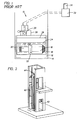
- a prior art hydraulic power unit is illustrated in a schematic machine room.
- the device 10 is generally mounted upon a type of support 12 within room 14.
- Tank 16 occupies a large portion of the machine room 14.
- the motor 18 and pump 20 are illustrated as mounted within tank 16 and are completely submerged in oil 22.
- the minimum oil level is indicated at 24 in the figure.
- the maximum oil level 26 will illustrate the difference between the oil required to maintain the pump and motor in a submerged condition and the oil required to operate the piston of the hydraulic elevator system. In many configurations more oil is actually required to submerge the motor and pump than is required to run the elevator. Because of this, very large tanks 16 are required to handle the amount of oil. Furthermore, a significant cost is incurred by the reservoiring of so much oil.
- valve block 28 Mounted atop tank 16 is a valve block 28 which generally also includes a shut-off valve 30.
- Valve block 28 is configured to supply low to medium pressure oil at about 12 to 45 bar to the cylinder 32 of the elevator system and allow oil to return to the tank 16 when the elevator car of the elevator system is lowered requiring the bleed-off of pressure from cylinder 32 and piston 34. Since space is an expensive commodity in modern building architecture, machine roomless elevator systems are becoming more accepted and in fact demanded. Because of the size of the hydraulic power unit 10 in a conventional hydraulic elevator system, building a hydraulic elevator system without a machine room has heretofore been nearly impossible. The elevator art is thus in need of a system that allows the hydraulic elevator power unit to be mounted such that a machine room is not required.
- a novel hydraulic power unit is created by vertically configuring various components of the unit and modifying internal structure of the tank thereof in order to maintain oil levels and temperatures required for motor and pump operation while avoiding the necessity of the large volumes of oil required in the prior art.
- the invention further provides for cooling of the oil reservoir surrounding the motor and pump.
- the invention preferably provides an insulated cover for the valve block assembly thus ameliorating the noise transmitted through the valve block.
- the hydraulic power unit of the invention is rendered significantly more compact than its conventional cousin enabling the fitment of the hydraulic power unit in the hoistway with the elevator car.
- the unit is placed in a clearance space between a wall of the hoistway and side of the elevator car.
- the invention preferably locates the unit in the hoistway and the machine room is deleted, a conventional rescue pump is inconvenient to use as it requires a technician or rescue personnel to enter the hoistway to operate the same.
- the invention therefore preferably includes a rescue pump located more conveniently.
- the invention enables compliance with market desires and emerging industry regulations by eliminating the need for a machine room in hydraulic elevator systems.
- the invention locates a new hydraulic power unit 40 in clearance space around elevator car 42 and/or framework 44.
- Car 46 and piston 48 are otherwise conventional. Because of the particular construction and configuration of elements within power unit 40, the unit is small enough to fit in clearance space in the hoistway such as the location in which it is illustrated in the figure. It should be understood that the figure represents but one possible embodiment, other possible embodiments include placement in other clearance spaces within the hoistway.
- FIGURES 3-5 the hydraulic power unit 40 of the invention is illustrated in detail.
- a vertically oriented tank 50 of unit 40 and associated mounting hardware is shown.
- Tank 50 comprises sheet material, preferably metal, which is bent or otherwise constructed to rest in a preferably rectangular shape and which is sealed at all side and bottom seams so that it will prevent leaking of the hydraulic fluid (oil) contained therein.
- a minimum level of oil is represented at broken line 52 and a maximum level is represented at broken line 54.
- Tank 50 is mounted upon tank suspensions 56 which are preferably fastened to a support structure such as a wall through flange 58.
- Suspensions 56 provide a further flange 60 which is used to bolt to spacer 62 with fasteners 64 in a preferred embodiment.
- Spacer 62 is illustrated as a C-channel although it will be understood that other structures may be substituted.
- Spacer 62 provides a mounting surface 66 through which a fastener 68 extends and upon which a bushing 70 rests. Fastener 68 then extends through a base flange 72 of tank 50.
- Another bushing 74 is placed upon fastener 68 and then a nut 76 is tightened thereupon.
- the arrangement is preferred to provide vibration damping for the unit 40 which reduces noise emissions. Further reducing noise emissions are cover 78 which is mounted atop tank 50 and provides noise insulation for a valve block housed herewith.
- a valve block 80 is mounted inside of cover 78.
- Such valve blocks are commercially available from Otis Elevator Company, CEAM via pradazzo N. 4/2, 40012 Calderara di Reno (BO) ITALIA.
- Block 80 is mounted on plate 82.
- Plate 82 includes a plurality of orifices for through passage of a plurality of draining pipes 84 which drain oil from piloting valves during operation of the power unit 40.
- Plate 82 also supports discharge hose 86 which discharges oil from an acceleration spool and a pressure relief valve which are internal to block 80 and known to the art.
- motor tank 88 which is attached to plate 82 in spaced relation by arms 90.
- arms 90 are attached to motor tank 88 with bushings 92 to reduce vibration and associated noise.
- Tank 88 is preferably constructed of sheet metal material and in a preferred embodiment is cylindrical in shape.
- the tank is sized appropriately to contain the motor being employed for the application so as to maintain the motor immersed in an oil or other hydraulic fluid at all times.
- the motor is attached to a pump 94 which extends from the bottom of motor tank 88 to what would be the bottom of tank 50 if shown in this drawing.
- Motor tank 88 and plate 82 along with all related components are supported within tank 50 by feet 96 and 98 which are preferably bushed with a vibration absorbent bushing 100.
- a high pressure line 102 is visible in the drawing in exploded form which in operation ferrys high pressure fluid from pump 94 to valve block 80.
- the high pressure fluid (oil) is then distributed to the piston of the elevator through the auxiliary valve block 104 and through line 106 (see FIGURE 6).
- a return line 108 returns fluid from the piston to the tank 50.
- the motor (not shown) always remains submerged in oil.
- the oil in the motor tank 88 is cooled by the bleed oil from discharge hose 86 and draining pipes 84 during descent of the elevator car and by bleed oil from the pump into tank 88 during upward movement of the elevator car 42. More specifically, upon an elevator car call, the motor is activated and the pump pressurizes the fluid headed for the piston. Some of this pressurized fluid bleeds from the pump 94 into the motor tank 88 due to the intentional lack of a seal at the interface of the motor and pump 94. Preferably, only a bushing is installed at this interface to maintain operating parameters of the pump but to facilitate the bleed.
- the bleed oil is cooler than the oil in motor tank 88.
- the bleed oil during this phase of operation bleeds in from the bottom of tank 88 and because the oil is cooler, the warmer oil in the motor tank 88 spills over the top thereof.
- the oil in the motor tank 88 is thus replaced by the cooler bleed oil and cools the motor.
- bleed off oil from the valve block enters the top of the motor tank 88 thus also cooling the motor.
- the temperature of the oil in motor tank 88 remains at or below 70°C and the motor (not shown) remains at or below 100°C. This is because the bleed oil is cooler than the indicated temperatures when introduced to motor tank 88.
- the oil is cooler because of environmental cooling thereof in the outer tank and the piston. The operation of the car itself due to wind currents it creates in the hoistway assists in the environmental cooling.
- the invention allows virtually all of the oil in outer tank 50 to be used to lift the elevator car while still keeping the motor submerged in its own motor tank 88. For this reason, less total oil is necessary and a smaller effective exterior dimension is achieved.
- the power unit 40 is fittable into clearance spaces in the hoistway and does not require the construction of a machine room.
- FIGURE 7 Another embodiment of the invention is illustrated in FIGURE 7 from a top plan view.
- the power unit 40 is located at the side of the elevator car 110 between guide rails 112 and brackets 114.
- rollers or sliding shoes 116 piston 118; pully 120; piston bracket 122; ropes fixing plate 124; uprights 126 and car doors 128.
- auxiliary block 104 including a hand pump 132 for lifting the elevator car to a next higher floor and, alternatively, a valve 134 to allow fluid in the elevator piston to move back into the reservoir to allow the elevator car to descend to the next floor.
- hoses 106 and 108 are provided as shown.
- a three way valve located at the interface between hose 106 and valve block 80 which can be positioned to pump fluid into hose 106 and back through hose 108 for initial priming. This is done by signalling an elevator car call with the valve in the prime position. Fluid pressurized by the pump will thus be urged through the hoses 106 and 108 and through the auxiliary block 104. Subsequent to this operation the valve is set to normal operation and it does not need to be activated again unless disassembly of the rescue pump assembly is necessary for maintenance or repair.
Landscapes
- Engineering & Computer Science (AREA)
- Automation & Control Theory (AREA)
- Structural Engineering (AREA)
- Civil Engineering (AREA)
- Mechanical Engineering (AREA)
- Types And Forms Of Lifts (AREA)
- Fluid-Pressure Circuits (AREA)
Abstract
Description
- The invention relates to hydraulic elevators. More particularly, the invention relates to a pump and tank for a hydraulic power unit.
- Hydraulic elevator systems are popular for lower rise applications since installation cost is generally lower than traction type elevator systems. The car of a hydraulic elevator system is displaced upwardly and downwardly within a hoistway by a piston disposed within a drive cylinder located at the base of the elevator hoistway. In order to provide pressurized fluid to the drive cylinder and, on demand, drive the piston and elevator car connected thereto upwardly, a pump and motor assembly is required. Commonly pump and motor assemblies of the prior art were maintained in a machine room wherein a large horizontally disposed tank contained the pump and motor therewithin and sufficient oil to both drive the elevator car to its highest intended stopping point and still cover the motor and pump. Such tanks are very large because of the amount of oil required to both drive the piston and keep the motor and pump submerged. A benefit of the prior art arrangement is that noise generated by the motor and pump is contained substantially to the machine room and therefore is insulated from the elevator car. Referring to Figure 1, a prior art hydraulic power unit is illustrated in a schematic machine room. The
device 10 is generally mounted upon a type ofsupport 12 withinroom 14.Tank 16 occupies a large portion of themachine room 14. Themotor 18 andpump 20 are illustrated as mounted withintank 16 and are completely submerged inoil 22. It will be appreciated that the minimum oil level is indicated at 24 in the figure. Themaximum oil level 26 will illustrate the difference between the oil required to maintain the pump and motor in a submerged condition and the oil required to operate the piston of the hydraulic elevator system. In many configurations more oil is actually required to submerge the motor and pump than is required to run the elevator. Because of this, verylarge tanks 16 are required to handle the amount of oil. Furthermore, a significant cost is incurred by the reservoiring of so much oil. - Mounted
atop tank 16 is avalve block 28 which generally also includes a shut-offvalve 30. Valveblock 28 is configured to supply low to medium pressure oil at about 12 to 45 bar to thecylinder 32 of the elevator system and allow oil to return to thetank 16 when the elevator car of the elevator system is lowered requiring the bleed-off of pressure fromcylinder 32 andpiston 34. Since space is an expensive commodity in modern building architecture, machine roomless elevator systems are becoming more accepted and in fact demanded. Because of the size of thehydraulic power unit 10 in a conventional hydraulic elevator system, building a hydraulic elevator system without a machine room has heretofore been nearly impossible. The elevator art is thus in need of a system that allows the hydraulic elevator power unit to be mounted such that a machine room is not required. - The above-identified drawbacks of the priorart are overcome or allenated by the hydraulic power unit of the invention in its various aspects.
- A novel hydraulic power unit is created by vertically configuring various components of the unit and modifying internal structure of the tank thereof in order to maintain oil levels and temperatures required for motor and pump operation while avoiding the necessity of the large volumes of oil required in the prior art. The invention further provides for cooling of the oil reservoir surrounding the motor and pump. Finally the invention preferably provides an insulated cover for the valve block assembly thus ameliorating the noise transmitted through the valve block.
- In the vertical configuration made possible by the present invention, the hydraulic power unit of the invention is rendered significantly more compact than its conventional cousin enabling the fitment of the hydraulic power unit in the hoistway with the elevator car. Preferably, the unit is placed in a clearance space between a wall of the hoistway and side of the elevator car. By allowing for in-hoistway containment of the hydraulic power unit, the need for a machine room is obviated.
- Since the invention preferably locates the unit in the hoistway and the machine room is deleted, a conventional rescue pump is inconvenient to use as it requires a technician or rescue personnel to enter the hoistway to operate the same. The invention therefore preferably includes a rescue pump located more conveniently.
- The present invention will now be described, by way of example only, with reference to the accompanying drawings in which:
- FIGURE 1 is a representation of a prior art hydraulic power unit within a machine room;
- FIGURE 2 is a schematic perspective view of a hydraulic elevator system of the invention and illustrating one location for the unit;
- FIGURE 3 is a perspective exterior view of the hydraulic pump unit of the invention;
- FIGURE 4 is an enlarged assembled elevation view of a portion of the illustration of FIGURE 2 within circumscription line 3-3;
- FIGURE 5 is a perspective view of the hydraulic pump unit of the invention with the outer housing removed to expose internal parts of the invention;
- FIGURE 6 is a schematic representation of the invention connected to an auxiliary valve block and electronic board in a controller cabinet; and
- FIGURE 7 is a top plan view of a hoistway illustrating an alternate location for the hydraulic pump unit.
- The invention enables compliance with market desires and emerging industry regulations by eliminating the need for a machine room in hydraulic elevator systems. Referring to FIGURE 2, the invention locates a new
hydraulic power unit 40 in clearance space aroundelevator car 42 and/orframework 44. Car 46 and piston 48 are otherwise conventional. Because of the particular construction and configuration of elements withinpower unit 40, the unit is small enough to fit in clearance space in the hoistway such as the location in which it is illustrated in the figure. It should be understood that the figure represents but one possible embodiment, other possible embodiments include placement in other clearance spaces within the hoistway. - Referring to FIGURES 3-5, the
hydraulic power unit 40 of the invention is illustrated in detail. In FIGURE 3, a vertically orientedtank 50 ofunit 40 and associated mounting hardware is shown.Tank 50 comprises sheet material, preferably metal, which is bent or otherwise constructed to rest in a preferably rectangular shape and which is sealed at all side and bottom seams so that it will prevent leaking of the hydraulic fluid (oil) contained therein. A minimum level of oil is represented atbroken line 52 and a maximum level is represented atbroken line 54. -
Tank 50 is mounted upontank suspensions 56 which are preferably fastened to a support structure such as a wall throughflange 58.Suspensions 56 provide afurther flange 60 which is used to bolt to spacer 62 withfasteners 64 in a preferred embodiment.Spacer 62 is illustrated as a C-channel although it will be understood that other structures may be substituted.Spacer 62 provides amounting surface 66 through which afastener 68 extends and upon which a bushing 70 rests. Fastener 68 then extends through abase flange 72 oftank 50. Anotherbushing 74 is placed uponfastener 68 and then anut 76 is tightened thereupon. The arrangement is preferred to provide vibration damping for theunit 40 which reduces noise emissions. Further reducing noise emissions arecover 78 which is mounted atoptank 50 and provides noise insulation for a valve block housed herewith. - Referring to FIGURE 5, the internal components of
unit 40 are illustrated. Avalve block 80 is mounted inside ofcover 78. Such valve blocks are commercially available from Otis Elevator Company, CEAM via pradazzo N. 4/2, 40012 Calderara di Reno (BO) ITALIA.Block 80 is mounted onplate 82.Plate 82 includes a plurality of orifices for through passage of a plurality of drainingpipes 84 which drain oil from piloting valves during operation of thepower unit 40.Plate 82 also supportsdischarge hose 86 which discharges oil from an acceleration spool and a pressure relief valve which are internal toblock 80 and known to the art. In discussing FIGURE 5 the relative terms "above" and "below" are intended only to relate to the drawing figure and not to imply any limitation to location of components of the invention. Belowplate 82 is positionedmotor tank 88 which is attached toplate 82 in spaced relation byarms 90. In a preferred embodiment,arms 90 are attached tomotor tank 88 withbushings 92 to reduce vibration and associated noise. -
Tank 88 is preferably constructed of sheet metal material and in a preferred embodiment is cylindrical in shape. The tank is sized appropriately to contain the motor being employed for the application so as to maintain the motor immersed in an oil or other hydraulic fluid at all times. The motor is attached to apump 94 which extends from the bottom ofmotor tank 88 to what would be the bottom oftank 50 if shown in this drawing.Motor tank 88 andplate 82 along with all related components are supported withintank 50 byfeet absorbent bushing 100. Finally, ahigh pressure line 102 is visible in the drawing in exploded form which in operation ferrys high pressure fluid frompump 94 tovalve block 80. The high pressure fluid (oil) is then distributed to the piston of the elevator through theauxiliary valve block 104 and through line 106 (see FIGURE 6). Areturn line 108 returns fluid from the piston to thetank 50. - Because of
motor tank 88, the motor (not shown) always remains submerged in oil. The oil in themotor tank 88 is cooled by the bleed oil fromdischarge hose 86 and drainingpipes 84 during descent of the elevator car and by bleed oil from the pump intotank 88 during upward movement of theelevator car 42. More specifically, upon an elevator car call, the motor is activated and the pump pressurizes the fluid headed for the piston. Some of this pressurized fluid bleeds from thepump 94 into themotor tank 88 due to the intentional lack of a seal at the interface of the motor and pump 94. Preferably, only a bushing is installed at this interface to maintain operating parameters of the pump but to facilitate the bleed. The bleed oil is cooler than the oil inmotor tank 88. Since the bleed oil during this phase of operation bleeds in from the bottom oftank 88 and because the oil is cooler, the warmer oil in themotor tank 88 spills over the top thereof. The oil in themotor tank 88 is thus replaced by the cooler bleed oil and cools the motor. During the down operation, bleed off oil from the valve block, as stated above, enters the top of themotor tank 88 thus also cooling the motor. Based upon testing, the temperature of the oil inmotor tank 88 remains at or below 70°C and the motor (not shown) remains at or below 100°C. This is because the bleed oil is cooler than the indicated temperatures when introduced tomotor tank 88. The oil is cooler because of environmental cooling thereof in the outer tank and the piston. The operation of the car itself due to wind currents it creates in the hoistway assists in the environmental cooling. - The invention allows virtually all of the oil in
outer tank 50 to be used to lift the elevator car while still keeping the motor submerged in itsown motor tank 88. For this reason, less total oil is necessary and a smaller effective exterior dimension is achieved. Thus thepower unit 40 is fittable into clearance spaces in the hoistway and does not require the construction of a machine room. - Another embodiment of the invention is illustrated in FIGURE 7 from a top plan view. In this embodiment the
power unit 40 is located at the side of theelevator car 110 betweenguide rails 112 andbrackets 114. One of skill in the art will appreciate the otherwise conventional aspects of the drawing which include rollers or slidingshoes 116;piston 118; pully 120;piston bracket 122;ropes fixing plate 124;uprights 126 andcar doors 128. - Another feature of the invention significantly improves the convenience of a rescue hand pump by locating the same in a control cabinet 130 near the elevator door on one of the floors serviced by the elevator system. The location avoids the need to enter the hoistway and additionally will allow for a visual confirmation of location of
elevator car 42 by the person operating the hand pump. To enable the benefits of this aspect of the invention reference is made to FIGURES 2 and 6. Within control cabinet 130 isauxiliary block 104 including ahand pump 132 for lifting the elevator car to a next higher floor and, alternatively, avalve 134 to allow fluid in the elevator piston to move back into the reservoir to allow the elevator car to descend to the next floor. In order to so locate theauxiliary valve block 104,hoses pump 132 provision must be made for priming the pump during installation thereof. Expediently, this is provided for by a three way valve located at the interface betweenhose 106 andvalve block 80 which can be positioned to pump fluid intohose 106 and back throughhose 108 for initial priming. This is done by signalling an elevator car call with the valve in the prime position. Fluid pressurized by the pump will thus be urged through thehoses auxiliary block 104. Subsequent to this operation the valve is set to normal operation and it does not need to be activated again unless disassembly of the rescue pump assembly is necessary for maintenance or repair. - Although the invention has been shown and described with respect to exemplary embodiments thereof; it should be understood by those skilled in the art that various changes, omissions, and additions may be made thereto, without departing from the scope of the invention.
Claims (10)
- An hydraulic elevator power unit (40) comprising:a vertically oriented elongated outer tank (50);a motor tank (88) mounted within said outer tank (50);a motor disposed within said motor tank (88); anda pump (94) operably connected to said motor.
- A hydraulic elevator power unit (40) as claimed in claim 1 wherein said unit further comprises a valve block (80) mounted to said outer tank.
- A hydraulic elevator power unit (40) as claimed in claim 2 wherein said unit includes an insulative cover disposed over said valve block (80).
- A hydraulic elevator power unit (40) as claimed in claims 2 or 3 wherein said unit further includes at least one fluid path from said valve block (80) to said motor tank (88).
- A hydraulic elevator power unit (40) as claimed in any preceding claim wherein said unit contains a hydraulic fluid whose level is variable within said outer tank (50) and is fixed within said motor tank (88).
- A hydraulic elevator system comprising:a hoistway having a plurality of walls;an elevator car (110) disposed in said hoistway;a hydraulically operated piston (118) disposed in said hoistway and operably attached to said car (110);a hydraulic power unit (40) disposed in a clearance space between said car (110) and at least one of said hoistway walls, said power unit (40) being operably connected to said piston (118).
- A hydraulic elevator system as claimed in claim 6 wherein said power unit (40) includes an outer tank (50) and an inner motor tank (88), said inner tank (88) maintaining a motor disposed therein submerged in hydraulic fluid.
- A hydraulic elevator system as claimed in claim 6 or 7 wherein said hydraulic power unit (40) is elongated and vertically oriented.
- A method for cooling a motor in an elevator system hydraulic power unit (40) comprising:maintaining said motor in a condition submerged in hydraulic oil in a motor tank (88), said motor tank (88) being a separate tank within an outer tank (50); andcooling hydraulic oil in said motor tank (88) by bleeding oil from a valve block (80) employed in said elevator system into said motor tank (88).
- A method for cooling a motor as claimed in claim 9 wherein said outer tank (50) holds hydraulic fluid employed to operate said elevator system.
Applications Claiming Priority (2)
| Application Number | Priority Date | Filing Date | Title |
|---|---|---|---|
| US09/385,750 US6371005B1 (en) | 1999-08-30 | 1999-08-30 | Hydraulic power unit for an elevator drive |
| EP00307422A EP1081083B1 (en) | 1999-08-30 | 2000-08-30 | Hydraulic power unit for an elevator drive |
Related Parent Applications (2)
| Application Number | Title | Priority Date | Filing Date |
|---|---|---|---|
| EP00307422.6 Division | 2000-08-30 | ||
| EP00307422A Division EP1081083B1 (en) | 1999-08-30 | 2000-08-30 | Hydraulic power unit for an elevator drive |
Publications (2)
| Publication Number | Publication Date |
|---|---|
| EP1642857A1 true EP1642857A1 (en) | 2006-04-05 |
| EP1642857B1 EP1642857B1 (en) | 2010-04-21 |
Family
ID=23522721
Family Applications (2)
| Application Number | Title | Priority Date | Filing Date |
|---|---|---|---|
| EP00307422A Expired - Lifetime EP1081083B1 (en) | 1999-08-30 | 2000-08-30 | Hydraulic power unit for an elevator drive |
| EP06000172A Expired - Lifetime EP1642857B1 (en) | 1999-08-30 | 2000-08-30 | Hydraulic power unit for an elevator drive |
Family Applications Before (1)
| Application Number | Title | Priority Date | Filing Date |
|---|---|---|---|
| EP00307422A Expired - Lifetime EP1081083B1 (en) | 1999-08-30 | 2000-08-30 | Hydraulic power unit for an elevator drive |
Country Status (4)
| Country | Link |
|---|---|
| US (2) | US6371005B1 (en) |
| EP (2) | EP1081083B1 (en) |
| DE (2) | DE60044268D1 (en) |
| ES (2) | ES2290001T3 (en) |
Families Citing this family (14)
| Publication number | Priority date | Publication date | Assignee | Title |
|---|---|---|---|---|
| DE102004040909B4 (en) * | 2004-06-17 | 2007-07-05 | Hydac Filtertechnik Gmbh | unit |
| DE102004032256B3 (en) * | 2004-07-03 | 2005-12-15 | Jungheinrich Ag | Hydraulic unit for industrial trucks |
| US7610977B2 (en) * | 2004-09-23 | 2009-11-03 | Crown Equipment Corporation | Lift truck having hydraulically separate main frame and power unit assembly |
| US7946391B2 (en) * | 2005-07-19 | 2011-05-24 | Bucher Hydraulics Ag | Hydraulic elevator without machine room |
| US8640829B2 (en) * | 2008-07-16 | 2014-02-04 | William P. Block, JR. | Hydraulic elevator system |
| CA2833119A1 (en) | 2011-05-20 | 2012-11-29 | Otis Elevator Company | Machine roomless hydraulic elevator system |
| CN103591429B (en) * | 2013-10-15 | 2017-01-04 | 启东中冶润滑液压设备有限公司 | Lubricating pump station for port mechanical equipment |
| US10160619B2 (en) * | 2014-06-30 | 2018-12-25 | Thyssenkrupp Elevator Corporation | Under car power unit for an elevator system |
| US20150375966A1 (en) * | 2014-06-30 | 2015-12-31 | Thyssenkrupp Elevator Corporation | Noise Abatement for Elevator Submersible Power Units |
| CN107032204B (en) * | 2015-07-20 | 2019-04-26 | 宁波弘威电梯有限公司 | A kind of elevator device and its working method |
| US11339772B2 (en) | 2019-12-13 | 2022-05-24 | Kti Hydraulics Inc. | Hydraulic power units with submerged motors |
| CN115053074A (en) * | 2019-12-14 | 2022-09-13 | Kti液压系统公司 | Hydraulic power unit with submersible motor |
| CN112299200B (en) * | 2020-09-22 | 2022-02-11 | 苏州科达液压电梯有限公司 | Safety protection device and safety protection method for hydraulic elevator |
| US12305670B2 (en) | 2021-08-03 | 2025-05-20 | Kti Hydraulics Inc. | Submersible hydraulic power units with interchangeable manifolds |
Citations (3)
| Publication number | Priority date | Publication date | Assignee | Title |
|---|---|---|---|---|
| JPS54119119A (en) * | 1978-03-08 | 1979-09-14 | Toshiba Corp | Elevating system for hydraulic elevators |
| US5078236A (en) * | 1989-09-29 | 1992-01-07 | Mitsubishi Denki Kabushiki Kaisha | Power unit for hydraulic elevator |
| EP0924155A2 (en) * | 1997-12-22 | 1999-06-23 | Otis Elevator Company | Hydraulic elevator without a machineroom |
Family Cites Families (14)
| Publication number | Priority date | Publication date | Assignee | Title |
|---|---|---|---|---|
| SE332698B (en) | 1968-05-30 | 1971-02-15 | Asea Ab | |
| US3764233A (en) * | 1971-11-15 | 1973-10-09 | Us Navy | Submersible motor-pump assembly |
| JPS55115601A (en) * | 1979-02-27 | 1980-09-05 | Toshiba Corp | Oil tank for hydraulic elevator |
| DE3629032C2 (en) * | 1986-08-27 | 1994-02-03 | Haushahn C Gmbh Co | Hoists, especially elevators |
| US4785915A (en) * | 1987-06-19 | 1988-11-22 | Westinghouse Electric Corp. | Elevator system monitoring cold oil |
| JPH02296497A (en) | 1989-05-11 | 1990-12-07 | Shoji Uchikawa | Microphone having three-directivity |
| JPH04354786A (en) * | 1991-05-31 | 1992-12-09 | Mitsubishi Electric Corp | Hydraulic elevator |
| JPH04354787A (en) * | 1991-05-31 | 1992-12-09 | Mitsubishi Electric Corp | Hydraulic elevator |
| JPH07114228A (en) | 1993-10-15 | 1995-05-02 | Canon Aptecs Kk | Document feeder and projection device |
| FI95456C (en) | 1994-05-04 | 1996-02-12 | Kone Oy | Arrangement of the elevator shaft wall opening and dashboard |
| US5906252A (en) * | 1996-10-29 | 1999-05-25 | Wang; Chiu Nan | Oil pressure auxiliary escape device of elevator |
| US6044933A (en) * | 1997-03-24 | 2000-04-04 | Inventio Ag | Hydraulic elevator |
| US6029448A (en) * | 1997-12-08 | 2000-02-29 | Fenner Fluid Power | Low noise hydraulic power unit for an auto-hoist lift |
| FR2773142B1 (en) * | 1997-12-29 | 2000-03-17 | Kadoche Emile | DRIVE DEVICE FOR HYDRAULIC ELEVATOR |
-
1999
- 1999-08-30 US US09/385,750 patent/US6371005B1/en not_active Expired - Lifetime
-
2000
- 2000-08-30 ES ES00307422T patent/ES2290001T3/en not_active Expired - Lifetime
- 2000-08-30 EP EP00307422A patent/EP1081083B1/en not_active Expired - Lifetime
- 2000-08-30 DE DE60044268T patent/DE60044268D1/en not_active Expired - Lifetime
- 2000-08-30 EP EP06000172A patent/EP1642857B1/en not_active Expired - Lifetime
- 2000-08-30 DE DE60036671T patent/DE60036671T2/en not_active Expired - Lifetime
- 2000-08-30 ES ES06000172T patent/ES2344217T3/en not_active Expired - Lifetime
-
2001
- 2001-09-10 US US09/950,375 patent/US6499567B2/en not_active Expired - Lifetime
Patent Citations (3)
| Publication number | Priority date | Publication date | Assignee | Title |
|---|---|---|---|---|
| JPS54119119A (en) * | 1978-03-08 | 1979-09-14 | Toshiba Corp | Elevating system for hydraulic elevators |
| US5078236A (en) * | 1989-09-29 | 1992-01-07 | Mitsubishi Denki Kabushiki Kaisha | Power unit for hydraulic elevator |
| EP0924155A2 (en) * | 1997-12-22 | 1999-06-23 | Otis Elevator Company | Hydraulic elevator without a machineroom |
Non-Patent Citations (1)
| Title |
|---|
| PATENT ABSTRACTS OF JAPAN vol. 003, no. 144 (M - 082) 28 November 1979 (1979-11-28) * |
Also Published As
| Publication number | Publication date |
|---|---|
| DE60036671D1 (en) | 2007-11-22 |
| EP1081083A3 (en) | 2002-07-10 |
| ES2344217T3 (en) | 2010-08-20 |
| DE60036671T2 (en) | 2008-07-24 |
| EP1642857B1 (en) | 2010-04-21 |
| EP1081083B1 (en) | 2007-10-10 |
| EP1081083A2 (en) | 2001-03-07 |
| US6499567B2 (en) | 2002-12-31 |
| US6371005B1 (en) | 2002-04-16 |
| DE60044268D1 (en) | 2010-06-02 |
| ES2290001T3 (en) | 2008-02-16 |
| US20020005114A1 (en) | 2002-01-17 |
Similar Documents
| Publication | Publication Date | Title |
|---|---|---|
| EP1642857B1 (en) | Hydraulic power unit for an elevator drive | |
| KR890001065B1 (en) | Hydraulic system for multistage hydraulic jack | |
| US6044933A (en) | Hydraulic elevator | |
| JP2009102149A (en) | Lifting device using hydraulic cylinder and emergency control method in the lifting device | |
| US20140216854A1 (en) | Machine roomless hydraulic elevator system | |
| US6719099B2 (en) | Integral elevator hydraulic power unit | |
| JP3140819U (en) | Lifting device using hydraulic cylinder | |
| US7946391B2 (en) | Hydraulic elevator without machine room | |
| EP1437321A1 (en) | Jack lifting-device, particularly for oleo-dynamic elevator systems | |
| JPH04169491A (en) | Hydraulically-operated elevator device | |
| JP5631570B2 (en) | Elevator equipment | |
| JP2528934B2 (en) | Fluid pressure elevator | |
| JP2025176317A (en) | Hydraulic power units, control panel integrated hydraulic power units, and hydraulic elevators | |
| US10246302B2 (en) | Auxiliary pumping unit | |
| JPH07165380A (en) | Hydraulic elevator | |
| JPH02163279A (en) | Power unit for hydraulic elevator | |
| Inglis | Hydraulic lifts | |
| JPH03249084A (en) | Hydraulic elevator | |
| JPH04354787A (en) | Hydraulic elevator | |
| JP2002060167A (en) | Hydraulic elevator equipment | |
| JPS62280180A (en) | Hydraulic elevator device | |
| JPH02152889A (en) | Power unit for hydraulic elevator | |
| JPH11335034A (en) | Attaching structure of oil pot for elevator | |
| JPH02147587A (en) | Power unit for hydraulic elevator | |
| JPS58183581A (en) | hydraulic elevator |
Legal Events
| Date | Code | Title | Description |
|---|---|---|---|
| PUAI | Public reference made under article 153(3) epc to a published international application that has entered the european phase |
Free format text: ORIGINAL CODE: 0009012 |
|
| AC | Divisional application: reference to earlier application |
Ref document number: 1081083 Country of ref document: EP Kind code of ref document: P |
|
| AK | Designated contracting states |
Kind code of ref document: A1 Designated state(s): AT BE CH CY DE DK ES FI FR GB GR IE IT LI LU MC NL PT SE |
|
| 17P | Request for examination filed |
Effective date: 20060606 |
|
| 17Q | First examination report despatched |
Effective date: 20060714 |
|
| AKX | Designation fees paid |
Designated state(s): DE ES IT |
|
| GRAP | Despatch of communication of intention to grant a patent |
Free format text: ORIGINAL CODE: EPIDOSNIGR1 |
|
| GRAS | Grant fee paid |
Free format text: ORIGINAL CODE: EPIDOSNIGR3 |
|
| GRAA | (expected) grant |
Free format text: ORIGINAL CODE: 0009210 |
|
| AC | Divisional application: reference to earlier application |
Ref document number: 1081083 Country of ref document: EP Kind code of ref document: P |
|
| AK | Designated contracting states |
Kind code of ref document: B1 Designated state(s): DE ES IT |
|
| REF | Corresponds to: |
Ref document number: 60044268 Country of ref document: DE Date of ref document: 20100602 Kind code of ref document: P |
|
| REG | Reference to a national code |
Ref country code: ES Ref legal event code: FG2A Ref document number: 2344217 Country of ref document: ES Kind code of ref document: T3 |
|
| PLBE | No opposition filed within time limit |
Free format text: ORIGINAL CODE: 0009261 |
|
| STAA | Information on the status of an ep patent application or granted ep patent |
Free format text: STATUS: NO OPPOSITION FILED WITHIN TIME LIMIT |
|
| 26N | No opposition filed |
Effective date: 20110124 |
|
| REG | Reference to a national code |
Ref country code: DE Ref legal event code: R082 Ref document number: 60044268 Country of ref document: DE Representative=s name: SCHMITT-NILSON SCHRAUD WAIBEL WOHLFROM PATENTA, DE |
|
| PGFP | Annual fee paid to national office [announced via postgrant information from national office to epo] |
Ref country code: DE Payment date: 20180719 Year of fee payment: 19 Ref country code: ES Payment date: 20180903 Year of fee payment: 19 Ref country code: IT Payment date: 20180719 Year of fee payment: 19 |
|
| REG | Reference to a national code |
Ref country code: DE Ref legal event code: R119 Ref document number: 60044268 Country of ref document: DE |
|
| PG25 | Lapsed in a contracting state [announced via postgrant information from national office to epo] |
Ref country code: DE Free format text: LAPSE BECAUSE OF NON-PAYMENT OF DUE FEES Effective date: 20200303 |
|
| PG25 | Lapsed in a contracting state [announced via postgrant information from national office to epo] |
Ref country code: IT Free format text: LAPSE BECAUSE OF NON-PAYMENT OF DUE FEES Effective date: 20190830 |
|
| REG | Reference to a national code |
Ref country code: ES Ref legal event code: FD2A Effective date: 20210108 |
|
| PG25 | Lapsed in a contracting state [announced via postgrant information from national office to epo] |
Ref country code: ES Free format text: LAPSE BECAUSE OF NON-PAYMENT OF DUE FEES Effective date: 20190831 |