EP1642827A2 - Aircraft with a lift system - Google Patents
Aircraft with a lift system Download PDFInfo
- Publication number
- EP1642827A2 EP1642827A2 EP05020683A EP05020683A EP1642827A2 EP 1642827 A2 EP1642827 A2 EP 1642827A2 EP 05020683 A EP05020683 A EP 05020683A EP 05020683 A EP05020683 A EP 05020683A EP 1642827 A2 EP1642827 A2 EP 1642827A2
- Authority
- EP
- European Patent Office
- Prior art keywords
- lift
- cabin
- bogie truck
- fuselage
- guiding
- Prior art date
- Legal status (The legal status is an assumption and is not a legal conclusion. Google has not performed a legal analysis and makes no representation as to the accuracy of the status listed.)
- Granted
Links
- 230000008878 coupling Effects 0.000 claims description 8
- 238000010168 coupling process Methods 0.000 claims description 8
- 238000005859 coupling reaction Methods 0.000 claims description 8
- 230000005540 biological transmission Effects 0.000 claims description 5
- 239000002184 metal Substances 0.000 claims description 2
- 229920002430 Fibre-reinforced plastic Polymers 0.000 claims 1
- 239000011151 fibre-reinforced plastic Substances 0.000 claims 1
- 238000013461 design Methods 0.000 abstract description 6
- 238000012423 maintenance Methods 0.000 abstract description 5
- 230000003993 interaction Effects 0.000 abstract 1
- 238000005253 cladding Methods 0.000 description 2
- 230000002411 adverse Effects 0.000 description 1
- 238000013459 approach Methods 0.000 description 1
- 238000011161 development Methods 0.000 description 1
- 230000018109 developmental process Effects 0.000 description 1
- 230000005489 elastic deformation Effects 0.000 description 1
- 238000010348 incorporation Methods 0.000 description 1
- 230000002401 inhibitory effect Effects 0.000 description 1
- 238000004519 manufacturing process Methods 0.000 description 1
- 238000000034 method Methods 0.000 description 1
- 238000000926 separation method Methods 0.000 description 1
Images

Classifications
-
- B—PERFORMING OPERATIONS; TRANSPORTING
- B66—HOISTING; LIFTING; HAULING
- B66B—ELEVATORS; ESCALATORS OR MOVING WALKWAYS
- B66B9/00—Kinds or types of lifts in, or associated with, buildings or other structures
- B66B9/02—Kinds or types of lifts in, or associated with, buildings or other structures actuated mechanically otherwise than by rope or cable
-
- B—PERFORMING OPERATIONS; TRANSPORTING
- B64—AIRCRAFT; AVIATION; COSMONAUTICS
- B64C—AEROPLANES; HELICOPTERS
- B64C1/00—Fuselages; Constructional features common to fuselages, wings, stabilising surfaces or the like
- B64C1/22—Other structures integral with fuselages to facilitate loading, e.g. cargo bays, cranes
-
- B—PERFORMING OPERATIONS; TRANSPORTING
- B64—AIRCRAFT; AVIATION; COSMONAUTICS
- B64D—EQUIPMENT FOR FITTING IN OR TO AIRCRAFT; FLIGHT SUITS; PARACHUTES; ARRANGEMENT OR MOUNTING OF POWER PLANTS OR PROPULSION TRANSMISSIONS IN AIRCRAFT
- B64D11/00—Passenger or crew accommodation; Flight-deck installations not otherwise provided for
- B64D11/0007—Devices specially adapted for food or beverage distribution services
-
- B—PERFORMING OPERATIONS; TRANSPORTING
- B64—AIRCRAFT; AVIATION; COSMONAUTICS
- B64D—EQUIPMENT FOR FITTING IN OR TO AIRCRAFT; FLIGHT SUITS; PARACHUTES; ARRANGEMENT OR MOUNTING OF POWER PLANTS OR PROPULSION TRANSMISSIONS IN AIRCRAFT
- B64D9/00—Equipment for handling freight; Equipment for facilitating passenger embarkation or the like
-
- B—PERFORMING OPERATIONS; TRANSPORTING
- B66—HOISTING; LIFTING; HAULING
- B66B—ELEVATORS; ESCALATORS OR MOVING WALKWAYS
- B66B11/00—Main component parts of lifts in, or associated with, buildings or other structures
- B66B11/02—Cages, i.e. cars
- B66B11/0206—Car frames
-
- B—PERFORMING OPERATIONS; TRANSPORTING
- B64—AIRCRAFT; AVIATION; COSMONAUTICS
- B64C—AEROPLANES; HELICOPTERS
- B64C1/00—Fuselages; Constructional features common to fuselages, wings, stabilising surfaces or the like
- B64C2001/0018—Fuselages; Constructional features common to fuselages, wings, stabilising surfaces or the like comprising two decks adapted for carrying passengers only
- B64C2001/0027—Fuselages; Constructional features common to fuselages, wings, stabilising surfaces or the like comprising two decks adapted for carrying passengers only arranged one above the other
-
- B—PERFORMING OPERATIONS; TRANSPORTING
- B64—AIRCRAFT; AVIATION; COSMONAUTICS
- B64C—AEROPLANES; HELICOPTERS
- B64C1/00—Fuselages; Constructional features common to fuselages, wings, stabilising surfaces or the like
- B64C2001/0018—Fuselages; Constructional features common to fuselages, wings, stabilising surfaces or the like comprising two decks adapted for carrying passengers only
- B64C2001/0036—Fuselages; Constructional features common to fuselages, wings, stabilising surfaces or the like comprising two decks adapted for carrying passengers only arranged side by side at the same level
Definitions
- the invention relates to an aircraft with a lift system, wherein the lift services several decks in the aircraft, and can travel down to the landing strip through an opening on the fuselage underside.
- US 4,653,707 proposes an onboard lift that services various decks in the aircraft along with the landing strip level.
- the lift cabin exits through an opening in the fuselage and travels downward, transporting passengers or goods.
- the structure consists of a guide shaft secured in the aircraft, which envelops the actual cabin on all sides. In light of the guide function, the shaft must be able to traverse at least the distance to the ground. Since the shaft completely envelops the cabin as a force-conveying structural element, it must also be expected to be heavy.
- the drive consists of ropes and pulleys, making it complicated and high-maintenance.
- An object of the invention is to configure an onboard lift in an aircraft that enables lowering to ground level, and in particular has a weight-minimizing, low-maintenance design independent of fuselage deformation.
- the solution according to the invention provide for a compact structure and low level of complexity, wherein telescoping systems and cable winches are avoided in an advantageous embodiment.
- the special way in which the lift cabin is guided yields a lightweight design with sufficient stability. Therefore, the lift system according to the invention is simpler and lighter than previously known lift systems.
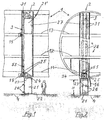
- Fig. 1 shows a longitudinal section through an aircraft fuselage 1 with a lift system 2.
- the fuselage 1 has three levels, namely a cargo area floor 11, a main deck 12 and an upper deck 13.
- a lift cabin 21 can be lowered to the landing strip 4, also allowing wheelchair-bound passengers to use it by way of a small ramp 22.
- the lift cabin 21 travels into a guide structure 3 by way of a bogie truck 24 secured to the cabin roof 23. Due to assembly and production considerations, the bogie truck 24 is detachably secured with connecting elements 57 (see Fig. 3ff).
- guide elements 25 of the bogie truck 24 are situated completely inside profile rails 31 in the fuselage 1, while the cabin 21 is completely exposed.
- This arrangement of the guide structure 3 and lift cabin 21 with mounted bogie truck 24 according to the invention makes it possible to design the cabin 21 with only the height required for passengers, wherein the lightweight-design bogie truck 24 is actually guided via the guiding elements 25.
- the drawing roughly depicts the relative dimensional ratios of a large capacity double-level aircraft with dimension H, which dimension H measures approx. 2 m.
- the height of the bogie truck 24 depends on the space between the upper and lower guiding elements 25, which is dimensioned in such a way as to leave enough of a safety gap to the fuselage shell 1 in the top lift position 21'.
- the distance between the guiding elements 25 here remains large enough to make the opposite forces generated by the tilting moment of the cabin 21 and acting on the elements 25 non-critical when the cabin 21 travels out of the fuselage 1. Since transverse forces are also encountered during flight as opposed to ground operations, additional guiding elements 26 are provided when needed, which leave the guiding structure 3 during egress from the fuselage 1. Upon reentry into the fuselage 1, the elements 26 hence provide additional guidance, so that the cabin 21 rests on a wider base as it traverses the interior of the fuselage 1, and any impact involving the lift shaft 27 is precluded, primarily during flight maneuvers.
- the guiding structure 3 consists of two profile rails 31, in which the guiding elements 25, 26 run and/or slide.
- the rails 31 are rigidly interconnected, and as the guiding structure 3 constitute the basis underlying the movement of the lift in the cabin.
- the structure 3 can advantageously be designed as a torsionally resistant box (see Fig. 4).
- the guiding structure 3 is secured by a fixed bearing 14 and movable bearing 15 to the fuselage 1 in a statically defined manner.
- the fixed bearing 14 absorbs forces in the x, y, z direction, while the movable bearing 15 only counters forces in the xy plane. Therefore, the lift shaft 27 consists only of cladding, and can have a relatively light structure due to the absence of forces.
- the lift is driven via low-noise toothed belts 55, which are coupled to the bogie truck 24 (see Fig. 3 and 4 for a more detailed description).
- Fig. 2 shows the cross section through the aircraft fuselage 1 and the lift system 2 corresponding to Fig. 1.
- a flap 16 is provided on the fuselage underside for ensuring lift egress and pressure tightness when closed.
- the lift shaft 27 is here incorporated out of center directly next to an aisle, which offers advantages in terms of lift access and seating arrangement; however, central incorporation is also possible.
- the shaft 27 has doors 28 on each deck; however, the door in the cargo area has a smaller height.
- Fig. 3 shows a diagrammatic section of a side view of the lower lift area, with the following primary components: profile rails 31, bogie truck 24, lift cabin 21, fixed bearings 14 and drive 5.
- the drive motor 51 with coupling-braking unit 52 coupled thereto sits on a bearing block 53, which is directly connected with the guiding structure 3. That is, the drive 5 forms a single unit with the guiding structure 3, thereby remaining unaffected by fuselage cell deformation.
- Two toothed belts 55 are driven by drive elements not described in any greater detail on Fig. 3 and by two driving wheels 54 each secured laterally to the structure 3. These have deflection pulleys above in the fuselage, making it possible to adjust the belt tension.
- the two toothed belts 55 are connected by coupling elements 56 with the bogie truck 24.
- the guiding elements 25 absorb the transverse forces or the counter forces from the cabin moment, only longitudinal forces, in a z-direction, act on the toothed belts 55 at the coupling elements 56.
- the guiding elements 25 are depicted as roller pairs in the drawing; however, other solutions are possible, e.g., sliding blocks made of plastic.
- the bogie truck 24 is flanged to the cabin roof 28 by screws 57 or the like, thereby easily enabling a separation for maintenance-related disassembly.
- the bogie truck 24 can then also be detached via the coupling elements 56 from the toothed belts 55, and the latter can be changed out as required.
- the toothed belts 55 are easy to assemble in that they lie outside the guiding structure 3.
- the fixed bearing 14 can also be formed as gimbals, if needed. This is denoted on the drawing by an additional rotational axis 17.
- the forces acting on the guiding structure 3 are in this way partially absorbed by the spars of the aircraft structure, e.g., the cargo area floor 11. The remaining forces are released on the movable bearing 15 located further up.
- the profile rails 31 are somewhat conical at the lower end, denoted here as an inclined profile catch 33.
- Fig. 4 shows a section of Fig. 3 in a horizontal projection.
- the lift shaft 27 envelops the lift cabin 21 without any contact. Since all forces emanating from the lift movement are absorbed by the guiding structure 3 and/or the profile rails 31, the lift shaft 27 can be merely designed as a light cladding.
- the profile rails 31 together with the webs 32 and cover plates 34 form the integral guiding structure 3.
- the guiding elements 25 here depicted as track rollers move in the profile rails 31. These are hinged to the bogie truck 24, which preferably comprises and/or consists of light metal or plastic, and only negligibly increases the weight of the entire cabin unit.
- the toothed belts 55 are here arranged to the side of the guiding structure 3, which facilitates assembly.
- the connection to the bogie truck 24 is established via coupling elements 56.
- the drive motor 51 acts by way of a coupling-braking unit 52, e.g., via driving belt 58, on a gear transmission 59, which moves a driving wheel 54.
- the gear transmission 59 ensures that the opposing toothed belt 55 is driven by the connecting shaft 510. All drive units and shafts are secured to the bearing block 53, which is in turn screwed to the guiding structure 3. This ensures that lifting operations can take place independently of the elastic deformations of the fuselage 1 encountered in flight.
- The, here shown, drive train from the motor 51 to the gear transmission 59 can be realized as self-inhibiting gearing or some other configuration, as requirements warrant. It is also easily possible to arrange the toothed belts 55 in another way, e.g., have one half of the belt run inside the guiding structure 3, while the other half is connected outside with the bogie truck 24 via the coupling elements. This solution yields a more compact design, but incorporating and dismantling is more complicated during the assembly process, which might be tolerated given long replacement intervals if space considerations were to make such a solution preferable.
Landscapes
- Engineering & Computer Science (AREA)
- Aviation & Aerospace Engineering (AREA)
- Mechanical Engineering (AREA)
- Structural Engineering (AREA)
- Civil Engineering (AREA)
- Automation & Control Theory (AREA)
- Types And Forms Of Lifts (AREA)
- Cage And Drive Apparatuses For Elevators (AREA)
- Body Structure For Vehicles (AREA)
- Lift-Guide Devices, And Elevator Ropes And Cables (AREA)
- Handcart (AREA)
- Forklifts And Lifting Vehicles (AREA)
Abstract
Description
- The invention relates to an aircraft with a lift system, wherein the lift services several decks in the aircraft, and can travel down to the landing strip through an opening on the fuselage underside.
- The steady rise in air traffic is being accompanied by the increased use of double-decker aircraft. The use of onboard lifts to transport cargo between the decks in such airplanes is known from WO 00/30422, for example. In addition, it is desirable in such aircraft that the lift also be able to approach another lower level and service the landing strip level. This document here provides for a scissor lift to lower cargo comprised of boxes, which directly handles the payload. Such a system does not enable passenger transport. Another mentioned solution involves a telescoping device, wherein an additional independently driven carriage travels out and down, lowering or raising the transport container with cargo. The additional independently driven carriage greatly increases the complexity, which adversely impacts maintenance and the weight of the lift system.
- Given a lift capable of navigating at ground level, it is desirable to convey both cargo and passengers from the ground directly to the respective cabin deck, for which the conventional cargo area loading equipment are hardly suited.
- US 4,653,707 proposes an onboard lift that services various decks in the aircraft along with the landing strip level. The lift cabin exits through an opening in the fuselage and travels downward, transporting passengers or goods. The structure consists of a guide shaft secured in the aircraft, which envelops the actual cabin on all sides. In light of the guide function, the shaft must be able to traverse at least the distance to the ground. Since the shaft completely envelops the cabin as a force-conveying structural element, it must also be expected to be heavy. In addition, the drive consists of ropes and pulleys, making it complicated and high-maintenance.
- An object of the invention is to configure an onboard lift in an aircraft that enables lowering to ground level, and in particular has a weight-minimizing, low-maintenance design independent of fuselage deformation.
- This object is achieved by the features specified in claim 1.
- With respect to the possibility of a ground-navigable lift for cargo and passenger transport, it is particularly advantageous that the solution according to the invention provide for a compact structure and low level of complexity, wherein telescoping systems and cable winches are avoided in an advantageous embodiment. The special way in which the lift cabin is guided yields a lightweight design with sufficient stability. Therefore, the lift system according to the invention is simpler and lighter than previously known lift systems.
- Further developments and advantageous embodiments of the invention are described in
claims 2 to 10. Details and additional details may be gleaned from the following description of an exemplary embodiment of the invention. - Shown on:
- Fig. 1
- is a longitudinal section through an aircraft fuselage with a lift system;
- Fig. 2
- is a cross section through the aircraft fuselage with a lift system;
- Fig. 3
- is a section in the vertical plane of the lower lift area;
- Fig. 4
- is a section in the horizontal plane of the lower lift area.
- Fig. 1 shows a longitudinal section through an aircraft fuselage 1 with a
lift system 2. The fuselage 1 has three levels, namely acargo area floor 11, amain deck 12 and anupper deck 13. As shown, alift cabin 21 can be lowered to thelanding strip 4, also allowing wheelchair-bound passengers to use it by way of asmall ramp 22. Thelift cabin 21 travels into aguide structure 3 by way of abogie truck 24 secured to thecabin roof 23. Due to assembly and production considerations, thebogie truck 24 is detachably secured with connecting elements 57 (see Fig. 3ff). When thelift cabin 21 travels into the lowest position,guide elements 25 of thebogie truck 24 are situated completely insideprofile rails 31 in the fuselage 1, while thecabin 21 is completely exposed. This arrangement of theguide structure 3 andlift cabin 21 with mountedbogie truck 24 according to the invention makes it possible to design thecabin 21 with only the height required for passengers, wherein the lightweight-design bogie truck 24 is actually guided via the guidingelements 25. The drawing roughly depicts the relative dimensional ratios of a large capacity double-level aircraft with dimension H, which dimension H measures approx. 2 m. The height of thebogie truck 24 depends on the space between the upper and lower guidingelements 25, which is dimensioned in such a way as to leave enough of a safety gap to the fuselage shell 1 in the top lift position 21'. The distance between the guidingelements 25 here remains large enough to make the opposite forces generated by the tilting moment of thecabin 21 and acting on theelements 25 non-critical when thecabin 21 travels out of the fuselage 1. Since transverse forces are also encountered during flight as opposed to ground operations, additional guidingelements 26 are provided when needed, which leave the guidingstructure 3 during egress from the fuselage 1. Upon reentry into the fuselage 1, theelements 26 hence provide additional guidance, so that thecabin 21 rests on a wider base as it traverses the interior of the fuselage 1, and any impact involving thelift shaft 27 is precluded, primarily during flight maneuvers. The guidingstructure 3 consists of twoprofile rails 31, in which the guidingelements rails 31 are rigidly interconnected, and as the guidingstructure 3 constitute the basis underlying the movement of the lift in the cabin. Thestructure 3 can advantageously be designed as a torsionally resistant box (see Fig. 4). To ensure that lift operation is unaffected by fuselage deformation, the guidingstructure 3 is secured by a fixed bearing 14 and movable bearing 15 to the fuselage 1 in a statically defined manner. The fixed bearing 14 absorbs forces in the x, y, z direction, while the movable bearing 15 only counters forces in the xy plane. Therefore, thelift shaft 27 consists only of cladding, and can have a relatively light structure due to the absence of forces. The lift is driven via low-noise toothed belts 55, which are coupled to the bogie truck 24 (see Fig. 3 and 4 for a more detailed description). - Fig. 2 shows the cross section through the aircraft fuselage 1 and the
lift system 2 corresponding to Fig. 1. On the fuselage underside aflap 16 is provided for ensuring lift egress and pressure tightness when closed. Thelift shaft 27 is here incorporated out of center directly next to an aisle, which offers advantages in terms of lift access and seating arrangement; however, central incorporation is also possible. Theshaft 27 hasdoors 28 on each deck; however, the door in the cargo area has a smaller height. - Fig. 3 shows a diagrammatic section of a side view of the lower lift area, with the following primary components:
profile rails 31,bogie truck 24,lift cabin 21,fixed bearings 14 and drive 5. Thedrive motor 51 with coupling-braking unit 52 coupled thereto sits on abearing block 53, which is directly connected with the guidingstructure 3. That is, the drive 5 forms a single unit with the guidingstructure 3, thereby remaining unaffected by fuselage cell deformation. Twotoothed belts 55 are driven by drive elements not described in any greater detail on Fig. 3 and by twodriving wheels 54 each secured laterally to thestructure 3. These have deflection pulleys above in the fuselage, making it possible to adjust the belt tension. The twotoothed belts 55 are connected bycoupling elements 56 with thebogie truck 24. Since the guidingelements 25 absorb the transverse forces or the counter forces from the cabin moment, only longitudinal forces, in a z-direction, act on thetoothed belts 55 at thecoupling elements 56. The guidingelements 25 are depicted as roller pairs in the drawing; however, other solutions are possible, e.g., sliding blocks made of plastic. Thebogie truck 24 is flanged to thecabin roof 28 byscrews 57 or the like, thereby easily enabling a separation for maintenance-related disassembly. Thebogie truck 24 can then also be detached via thecoupling elements 56 from thetoothed belts 55, and the latter can be changed out as required. Thetoothed belts 55 are easy to assemble in that they lie outside the guidingstructure 3. The fixedbearing 14 can also be formed as gimbals, if needed. This is denoted on the drawing by an additionalrotational axis 17. The forces acting on the guidingstructure 3 are in this way partially absorbed by the spars of the aircraft structure, e.g., thecargo area floor 11. The remaining forces are released on themovable bearing 15 located further up. To better thread theadditional guiding elements 26 as thecabin 21 ascends, the profile rails 31 are somewhat conical at the lower end, denoted here as aninclined profile catch 33. - Drive solutions other than the one described for driving the
toothed belts 55 are of course also possible. For example, the individual drive elements could be flanged directly to the guidingstructure 3 without a bearingblock 53, wherein the connectingshaft 510 could under certain conditions come to lie inside the profile rails 31. The guidingelements 25 lying below (track rollers in the drawing) would then have to edge higher on thebogie truck 24, however. - Fig. 4 shows a section of Fig. 3 in a horizontal projection. The
lift shaft 27 envelops thelift cabin 21 without any contact. Since all forces emanating from the lift movement are absorbed by the guidingstructure 3 and/or the profile rails 31, thelift shaft 27 can be merely designed as a light cladding. The profile rails 31 together with thewebs 32 andcover plates 34 form theintegral guiding structure 3. The guidingelements 25 here depicted as track rollers move in the profile rails 31. These are hinged to thebogie truck 24, which preferably comprises and/or consists of light metal or plastic, and only negligibly increases the weight of the entire cabin unit. Thetoothed belts 55 are here arranged to the side of the guidingstructure 3, which facilitates assembly. The connection to thebogie truck 24 is established viacoupling elements 56. Thedrive motor 51 acts by way of a coupling-braking unit 52, e.g., via drivingbelt 58, on agear transmission 59, which moves adriving wheel 54. Thegear transmission 59 ensures that the opposingtoothed belt 55 is driven by the connectingshaft 510. All drive units and shafts are secured to thebearing block 53, which is in turn screwed to the guidingstructure 3. This ensures that lifting operations can take place independently of the elastic deformations of the fuselage 1 encountered in flight. - The, here shown, drive train from the
motor 51 to thegear transmission 59 can be realized as self-inhibiting gearing or some other configuration, as requirements warrant. It is also easily possible to arrange thetoothed belts 55 in another way, e.g., have one half of the belt run inside the guidingstructure 3, while the other half is connected outside with thebogie truck 24 via the coupling elements. This solution yields a more compact design, but incorporating and dismantling is more complicated during the assembly process, which might be tolerated given long replacement intervals if space considerations were to make such a solution preferable. -
- 1
- Aircraft fuselage
11 Cargo area floor
12 Main deck
13 Upper deck
14 Fixed bearing
15 Movable bearing
16 Fuselage flap
17 Rotational axis - 2
- Lift
21 Cabin, 21' - top position
22 Ramp
23 Cabin roof
24 Bogie truck
25 Guiding elements
26 Additional guiding elements
27 Lift shaft
28 Shaft door - 3
- Guiding structure
31 Profile rails
32 Connecting webs
33 Inclined profile set
34 Cover plates - 4
- Landing strip
- 5
- Driving block
51 Drive motor
52 Coupling-braking unit
53 Bearing block
54 Drive wheel
55 Toothed belt
56 Coupling element
57 Connecting elements
58 Driving belt
59 Gear transmission
510 Connecting shaft - H
- Dimensional measure = about 2 m
Claims (12)
- An aircraft with a lift system for guiding a lift cabin, wherein the lift cabin services several decks in the aircraft, is traversable on a guiding structure supported inside the aircraft fuselage, and can travel down to the landing strip through an opening on the fuselage underside, wherein the lift cabin (21) is arranged on the guiding structure (3) by a bogie truck (24) arranged above the lift cabin roof (23), and the bogie truck (24) is actively connected with profile rails (31) of the guiding structure (3) via guiding elements (25), and the part of the bogie truck (24) carrying the guiding elements (25) remains in the fuselage (1) in the bottom lift position, while the lift cabin (21) is entirely driven out of the fuselage (1).
- The aircraft according to claim 1, wherein additional guiding elements (26) are secured to the lift cabin (21) and are introducable into the profile rails (31) from the bottom lift position during upward movement by way of an inclined profile catch (33).
- The aircraft according to one of claims 1 or 2, wherein the guiding elements (25, 26) are designed as track rollers or sliding bodies.
- The aircraft according to one of claims 1 to 3, wherein the bogie truck (24) comprises and/or consists of light metal or fiber-reinforced plastic, and is detachably assembled with the cabin roof (23) by connecting elements (57).
- The aircraft according to one of claims 1 to 4, wherein a lift drive (5) actively connected with the bogie truck (24) is designed as a toothed belt drive (55).
- The aircraft according to claim 5, wherein the toothed belts (55) actively connected with the bogie truck (24) via coupling elements (56) are situated outside the guiding structure (3).
- The aircraft according to claim 5, wherein the toothed belts (55) actively connected with the bogie truck (24) are situated partially inside the guiding structure (3) in such a way that one half of the rotating toothed belt (55) runs inside the guiding structure (3), while the other half is connected outside with the bogie truck (24) via the coupling elements (26).
- The aircraft according to one of claims 1 to 7, wherein the lift cabin (2) is situated inside a lift shaft (27), wherein the lift cabin (21) is guided inside the lift shaft (27) without any contact.
- The aircraft according to one of claims 1 to 8, wherein the lift shaft (27) is made out of light structural elements.
- The aircraft according to one of claims 1 to 9, wherein the guiding structure (3) is designed as a distortion-resistant and rigid torsional box using profile rails (31), connecting webs (32) and cover plates (34) as the components.
- The aircraft according to one of claims 1 to 10, wherein the lift drive (5) comprises a drive motor (51), a coupling-braking unit (52) and transmission means (58, 59, 510) for the drive wheel (54), which powers the toothed belts (55).
- The aircraft according to one of claims 1 to 11, wherein the lift drive (5) is mounted to the guiding structure (3).
Applications Claiming Priority (2)
| Application Number | Priority Date | Filing Date | Title |
|---|---|---|---|
| DE102004046146A DE102004046146B4 (en) | 2004-09-23 | 2004-09-23 | Airplane with a lift facility |
| US63133504P | 2004-11-29 | 2004-11-29 |
Publications (3)
| Publication Number | Publication Date |
|---|---|
| EP1642827A2 true EP1642827A2 (en) | 2006-04-05 |
| EP1642827A3 EP1642827A3 (en) | 2008-03-05 |
| EP1642827B1 EP1642827B1 (en) | 2011-08-24 |
Family
ID=36061904
Family Applications (1)
| Application Number | Title | Priority Date | Filing Date |
|---|---|---|---|
| EP05020683A Expired - Lifetime EP1642827B1 (en) | 2004-09-23 | 2005-09-22 | Aircraft with a lift system |
Country Status (4)
| Country | Link |
|---|---|
| US (1) | US7318566B2 (en) |
| EP (1) | EP1642827B1 (en) |
| AT (1) | ATE521534T1 (en) |
| DE (1) | DE102004046146B4 (en) |
Cited By (4)
| Publication number | Priority date | Publication date | Assignee | Title |
|---|---|---|---|---|
| WO2012048944A3 (en) * | 2010-10-13 | 2012-10-11 | Detlef Henry Friedrich | Rail transport system for loading and unloading the galley of an aeroplane |
| EP2815971A1 (en) * | 2013-06-17 | 2014-12-24 | Airbus Operations GmbH | Monument for an aircraft comprising a lift apparatus |
| US11390490B2 (en) * | 2020-01-21 | 2022-07-19 | Otis Elevator Company | Cantilevered climbing elevator |
| CN119831678A (en) * | 2024-12-10 | 2025-04-15 | 中国民航信息网络股份有限公司 | Air ticket cabin lifting method and device based on cabin lifting ticket, electronic equipment and storage medium |
Families Citing this family (7)
| Publication number | Priority date | Publication date | Assignee | Title |
|---|---|---|---|---|
| FR2917375B1 (en) * | 2007-06-15 | 2009-11-13 | Airbus France | AIRCRAFT HAVING A MOBILE PLATFORM BETWEEN TWO LEVELS OF THE AIRCRAFT |
| EP2488410B1 (en) * | 2009-10-13 | 2017-03-15 | Greenpoint Technologies, Inc. | Aircraft elevator system and method |
| FR2954276B1 (en) * | 2009-12-17 | 2012-03-23 | Airbus | DEVICE FOR THE OPTIMIZED STORAGE OF TROLLEYS |
| US8757327B2 (en) | 2011-04-15 | 2014-06-24 | L-3 Communications Integrated Systems Lp | Vehicle elevator systems and methods |
| US10214276B2 (en) | 2015-04-14 | 2019-02-26 | Shakil Hussain | Aircraft external viewing system, apparatus, and method |
| US9845155B2 (en) * | 2016-01-05 | 2017-12-19 | The Boeing Company | Systems and methods for conveying passengers, flight crew personnel, containers and food service carts |
| CN108146403B (en) * | 2018-02-13 | 2024-06-07 | 杭州中车车辆有限公司 | Straddle type monorail bogie assembly overhauling and replacing equipment |
Citations (2)
| Publication number | Priority date | Publication date | Assignee | Title |
|---|---|---|---|---|
| US4653707A (en) | 1984-12-28 | 1987-03-31 | The Boeing Company | Personnel elevator for commercial aircraft |
| WO2000030422A2 (en) | 1998-11-20 | 2000-06-02 | Reinoldus Transport- Und Robotertechnik Gmbh | Transportation device for transporting loads in a vertical direction between horizontal planes |
Family Cites Families (17)
| Publication number | Priority date | Publication date | Assignee | Title |
|---|---|---|---|---|
| US3463334A (en) * | 1967-04-17 | 1969-08-26 | Boeing Co | Cargo loading apparatus |
| US3552587A (en) * | 1968-04-16 | 1971-01-05 | Mc Donnell Douglas Corp | Powered hoist-baggage container handling system |
| US3693761A (en) * | 1970-08-28 | 1972-09-26 | Garrett Corp | Elevator system |
| US4022404A (en) * | 1975-10-22 | 1977-05-10 | The Boeing Company | Upper deck main galley in a three deck, wide-bodied passenger airplane |
| US4055317A (en) * | 1976-06-30 | 1977-10-25 | The Boeing Company | Aft main deck split level galley |
| FR2616121B1 (en) * | 1987-06-04 | 1990-10-26 | Aerospatiale | SELF-CONTAINED LOADING DEVICE FOR AIRCRAFT |
| US5322244A (en) * | 1992-03-17 | 1994-06-21 | Deutsche Aerospace Airbus Gmbh | Supply system for passenger aircraft |
| US5558181A (en) * | 1995-01-04 | 1996-09-24 | Bundo; Mutsuro | Elevator |
| US6340136B1 (en) * | 1995-08-07 | 2002-01-22 | Fuselage Engineering Service, Ltd. | Compact storing and retrieving apparatus particularly useful for aircraft |
| US5716300A (en) * | 1996-05-01 | 1998-02-10 | Sikorsky Aircraft Corporation | Isolated ring gear for planetary gear drive systems |
| DE19956403A1 (en) * | 1999-11-24 | 2001-06-07 | Eads Airbus Gmbh | Lift device for commercial aircraft has lift cage or platform located in supply shaft and by load unit can be lowered in vertical direction onto ground below through opening in fuselage |
| US6776263B2 (en) * | 2000-05-19 | 2004-08-17 | Esw-Extel Systems Wedel Gesellschaft Fuer Austruestung Mbh | Elevator system for the vertical transport of loads in an aircraft |
| US6808142B2 (en) * | 2000-06-06 | 2004-10-26 | Mitsubishi Heavy Industries, Ltd. | Aircraft with a plurality of upper and lower cabins functioning as cargo compartments or passenger cabins and method of loading cargos for aircraft |
| DE10158232C1 (en) * | 2001-11-16 | 2003-04-10 | Esw Extel Systems Wedel Ges Fu | Vertical transporter for aircraft loads has cylindrical cabin moving axially on mast with corresponding cross section |
| DE10204892B4 (en) * | 2002-02-06 | 2006-02-02 | Airbus Deutschland Gmbh | Conveyor for the vertical transport of catering containers in commercial aircraft |
| DE10305028B4 (en) * | 2003-02-07 | 2007-04-05 | Airbus Deutschland Gmbh | Vertical conveyor for the transport of food in an airplane with at least two decks arranged one above the other |
| US7494091B2 (en) * | 2005-02-22 | 2009-02-24 | The Boeing Company | Aircraft cart transport and stowage system |
-
2004
- 2004-09-23 DE DE102004046146A patent/DE102004046146B4/en not_active Expired - Fee Related
-
2005
- 2005-09-22 AT AT05020683T patent/ATE521534T1/en not_active IP Right Cessation
- 2005-09-22 EP EP05020683A patent/EP1642827B1/en not_active Expired - Lifetime
- 2005-09-23 US US11/233,889 patent/US7318566B2/en not_active Expired - Fee Related
Patent Citations (2)
| Publication number | Priority date | Publication date | Assignee | Title |
|---|---|---|---|---|
| US4653707A (en) | 1984-12-28 | 1987-03-31 | The Boeing Company | Personnel elevator for commercial aircraft |
| WO2000030422A2 (en) | 1998-11-20 | 2000-06-02 | Reinoldus Transport- Und Robotertechnik Gmbh | Transportation device for transporting loads in a vertical direction between horizontal planes |
Cited By (7)
| Publication number | Priority date | Publication date | Assignee | Title |
|---|---|---|---|---|
| WO2012048944A3 (en) * | 2010-10-13 | 2012-10-11 | Detlef Henry Friedrich | Rail transport system for loading and unloading the galley of an aeroplane |
| CN103153832A (en) * | 2010-10-13 | 2013-06-12 | 德特勒夫·亨利·弗里德里希 | Rail conveyor system for loading and unloading aircraft galleys |
| CN103153832B (en) * | 2010-10-13 | 2015-01-14 | 德特勒夫·亨利·弗里德里希 | Rail conveyor system for loading and unloading aircraft galleys |
| EP2815971A1 (en) * | 2013-06-17 | 2014-12-24 | Airbus Operations GmbH | Monument for an aircraft comprising a lift apparatus |
| US9469403B2 (en) | 2013-06-17 | 2016-10-18 | Airbus Operations Gmbh | Monument for an aircraft comprising a lift apparatus |
| US11390490B2 (en) * | 2020-01-21 | 2022-07-19 | Otis Elevator Company | Cantilevered climbing elevator |
| CN119831678A (en) * | 2024-12-10 | 2025-04-15 | 中国民航信息网络股份有限公司 | Air ticket cabin lifting method and device based on cabin lifting ticket, electronic equipment and storage medium |
Also Published As
| Publication number | Publication date |
|---|---|
| ATE521534T1 (en) | 2011-09-15 |
| US20070215754A1 (en) | 2007-09-20 |
| US7318566B2 (en) | 2008-01-15 |
| EP1642827A3 (en) | 2008-03-05 |
| DE102004046146B4 (en) | 2008-01-03 |
| DE102004046146A1 (en) | 2006-04-06 |
| EP1642827B1 (en) | 2011-08-24 |
Similar Documents
| Publication | Publication Date | Title |
|---|---|---|
| US3910264A (en) | Passenger loading ramp | |
| EP1642827B1 (en) | Aircraft with a lift system | |
| US6808142B2 (en) | Aircraft with a plurality of upper and lower cabins functioning as cargo compartments or passenger cabins and method of loading cargos for aircraft | |
| US8702036B2 (en) | System for overhead storage of cargo containers in upper lobe of aircraft | |
| US6302358B1 (en) | Quick Change system and method for converting an aircraft from a cargo mode to a passenger mode and vice versa | |
| US6212724B1 (en) | Passenger boarding bridge for narrow body aircraft | |
| EP3190048B1 (en) | System and methods for conveying passengers, flight crew personnel, containers and food service carts | |
| CN1478028A (en) | Height-adjustable railway freight car | |
| CN111762326A (en) | Cargo handling system and building | |
| US4395180A (en) | Engine unit maintenance complex | |
| CN105712153A (en) | Car safety protecting device | |
| JP6921111B2 (en) | Electric vehicle with elevating cabin for transporting people or goods | |
| CN212654925U (en) | Cargo handling system and building | |
| CN219969851U (en) | Unmanned delivery car | |
| CZ286378B6 (en) | Sectional train | |
| CN110748215B (en) | Suspended train warehouse-in and warehouse-out system, suspended train transfer device and suspended train garage | |
| CN103085989A (en) | Aircraft landing stairs for transporting passengers and lifting device thereof | |
| CN212953724U (en) | Buffer type elevator car | |
| CN202657253U (en) | Passenger steps used for transporting passenger | |
| CN113955045B (en) | Cabin elevator and process thereof | |
| US2981202A (en) | Mass transportation systems | |
| CN112830416B (en) | An ETV lifting transfer vehicle | |
| EP0616934B2 (en) | Elevator installation in a multiple deck railway vehicle | |
| CN223983121U (en) | Transfer devices and conveying equipment | |
| US12071324B2 (en) | Construction time use elevator shaft element, elevator arrangement and method |
Legal Events
| Date | Code | Title | Description |
|---|---|---|---|
| PUAI | Public reference made under article 153(3) epc to a published international application that has entered the european phase |
Free format text: ORIGINAL CODE: 0009012 |
|
| AK | Designated contracting states |
Kind code of ref document: A2 Designated state(s): AT BE BG CH CY CZ DE DK EE ES FI FR GB GR HU IE IS IT LI LT LU LV MC NL PL PT RO SE SI SK TR |
|
| AX | Request for extension of the european patent |
Extension state: AL BA HR MK YU |
|
| PUAL | Search report despatched |
Free format text: ORIGINAL CODE: 0009013 |
|
| AK | Designated contracting states |
Kind code of ref document: A3 Designated state(s): AT BE BG CH CY CZ DE DK EE ES FI FR GB GR HU IE IS IT LI LT LU LV MC NL PL PT RO SE SI SK TR |
|
| AX | Request for extension of the european patent |
Extension state: AL BA HR MK YU |
|
| 17P | Request for examination filed |
Effective date: 20080807 |
|
| AKX | Designation fees paid |
Designated state(s): AT BE BG CH CY CZ DE DK EE ES FI FR GB GR HU IE IS IT LI LT LU LV MC NL PL PT RO SE SI SK TR |
|
| GRAP | Despatch of communication of intention to grant a patent |
Free format text: ORIGINAL CODE: EPIDOSNIGR1 |
|
| GRAS | Grant fee paid |
Free format text: ORIGINAL CODE: EPIDOSNIGR3 |
|
| RAP1 | Party data changed (applicant data changed or rights of an application transferred) |
Owner name: AIRBUS OPERATIONS GMBH |
|
| GRAA | (expected) grant |
Free format text: ORIGINAL CODE: 0009210 |
|
| AK | Designated contracting states |
Kind code of ref document: B1 Designated state(s): AT BE BG CH CY CZ DE DK EE ES FI FR GB GR HU IE IS IT LI LT LU LV MC NL PL PT RO SE SI SK TR |
|
| REG | Reference to a national code |
Ref country code: GB Ref legal event code: FG4D |
|
| REG | Reference to a national code |
Ref country code: CH Ref legal event code: EP |
|
| REG | Reference to a national code |
Ref country code: IE Ref legal event code: FG4D |
|
| REG | Reference to a national code |
Ref country code: DE Ref legal event code: R096 Ref document number: 602005029667 Country of ref document: DE Effective date: 20111110 |
|
| REG | Reference to a national code |
Ref country code: NL Ref legal event code: VDEP Effective date: 20110824 |
|
| LTIE | Lt: invalidation of european patent or patent extension |
Effective date: 20110824 |
|
| PG25 | Lapsed in a contracting state [announced via postgrant information from national office to epo] |
Ref country code: FI Free format text: LAPSE BECAUSE OF FAILURE TO SUBMIT A TRANSLATION OF THE DESCRIPTION OR TO PAY THE FEE WITHIN THE PRESCRIBED TIME-LIMIT Effective date: 20110824 Ref country code: SE Free format text: LAPSE BECAUSE OF FAILURE TO SUBMIT A TRANSLATION OF THE DESCRIPTION OR TO PAY THE FEE WITHIN THE PRESCRIBED TIME-LIMIT Effective date: 20110824 Ref country code: LT Free format text: LAPSE BECAUSE OF FAILURE TO SUBMIT A TRANSLATION OF THE DESCRIPTION OR TO PAY THE FEE WITHIN THE PRESCRIBED TIME-LIMIT Effective date: 20110824 Ref country code: NL Free format text: LAPSE BECAUSE OF FAILURE TO SUBMIT A TRANSLATION OF THE DESCRIPTION OR TO PAY THE FEE WITHIN THE PRESCRIBED TIME-LIMIT Effective date: 20110824 Ref country code: IS Free format text: LAPSE BECAUSE OF FAILURE TO SUBMIT A TRANSLATION OF THE DESCRIPTION OR TO PAY THE FEE WITHIN THE PRESCRIBED TIME-LIMIT Effective date: 20111224 Ref country code: PT Free format text: LAPSE BECAUSE OF FAILURE TO SUBMIT A TRANSLATION OF THE DESCRIPTION OR TO PAY THE FEE WITHIN THE PRESCRIBED TIME-LIMIT Effective date: 20111226 |
|
| REG | Reference to a national code |
Ref country code: AT Ref legal event code: MK05 Ref document number: 521534 Country of ref document: AT Kind code of ref document: T Effective date: 20110824 |
|
| PG25 | Lapsed in a contracting state [announced via postgrant information from national office to epo] |
Ref country code: GR Free format text: LAPSE BECAUSE OF FAILURE TO SUBMIT A TRANSLATION OF THE DESCRIPTION OR TO PAY THE FEE WITHIN THE PRESCRIBED TIME-LIMIT Effective date: 20111125 Ref country code: SI Free format text: LAPSE BECAUSE OF FAILURE TO SUBMIT A TRANSLATION OF THE DESCRIPTION OR TO PAY THE FEE WITHIN THE PRESCRIBED TIME-LIMIT Effective date: 20110824 Ref country code: CY Free format text: LAPSE BECAUSE OF FAILURE TO SUBMIT A TRANSLATION OF THE DESCRIPTION OR TO PAY THE FEE WITHIN THE PRESCRIBED TIME-LIMIT Effective date: 20110824 Ref country code: PL Free format text: LAPSE BECAUSE OF FAILURE TO SUBMIT A TRANSLATION OF THE DESCRIPTION OR TO PAY THE FEE WITHIN THE PRESCRIBED TIME-LIMIT Effective date: 20110824 Ref country code: LV Free format text: LAPSE BECAUSE OF FAILURE TO SUBMIT A TRANSLATION OF THE DESCRIPTION OR TO PAY THE FEE WITHIN THE PRESCRIBED TIME-LIMIT Effective date: 20110824 Ref country code: AT Free format text: LAPSE BECAUSE OF FAILURE TO SUBMIT A TRANSLATION OF THE DESCRIPTION OR TO PAY THE FEE WITHIN THE PRESCRIBED TIME-LIMIT Effective date: 20110824 |
|
| PG25 | Lapsed in a contracting state [announced via postgrant information from national office to epo] |
Ref country code: BE Free format text: LAPSE BECAUSE OF FAILURE TO SUBMIT A TRANSLATION OF THE DESCRIPTION OR TO PAY THE FEE WITHIN THE PRESCRIBED TIME-LIMIT Effective date: 20110824 |
|
| PG25 | Lapsed in a contracting state [announced via postgrant information from national office to epo] |
Ref country code: CZ Free format text: LAPSE BECAUSE OF FAILURE TO SUBMIT A TRANSLATION OF THE DESCRIPTION OR TO PAY THE FEE WITHIN THE PRESCRIBED TIME-LIMIT Effective date: 20110824 Ref country code: SK Free format text: LAPSE BECAUSE OF FAILURE TO SUBMIT A TRANSLATION OF THE DESCRIPTION OR TO PAY THE FEE WITHIN THE PRESCRIBED TIME-LIMIT Effective date: 20110824 Ref country code: MC Free format text: LAPSE BECAUSE OF NON-PAYMENT OF DUE FEES Effective date: 20110930 |
|
| REG | Reference to a national code |
Ref country code: CH Ref legal event code: PL |
|
| PG25 | Lapsed in a contracting state [announced via postgrant information from national office to epo] |
Ref country code: RO Free format text: LAPSE BECAUSE OF FAILURE TO SUBMIT A TRANSLATION OF THE DESCRIPTION OR TO PAY THE FEE WITHIN THE PRESCRIBED TIME-LIMIT Effective date: 20110824 Ref country code: EE Free format text: LAPSE BECAUSE OF FAILURE TO SUBMIT A TRANSLATION OF THE DESCRIPTION OR TO PAY THE FEE WITHIN THE PRESCRIBED TIME-LIMIT Effective date: 20110824 Ref country code: IT Free format text: LAPSE BECAUSE OF FAILURE TO SUBMIT A TRANSLATION OF THE DESCRIPTION OR TO PAY THE FEE WITHIN THE PRESCRIBED TIME-LIMIT Effective date: 20110824 |
|
| REG | Reference to a national code |
Ref country code: IE Ref legal event code: MM4A |
|
| PG25 | Lapsed in a contracting state [announced via postgrant information from national office to epo] |
Ref country code: DK Free format text: LAPSE BECAUSE OF FAILURE TO SUBMIT A TRANSLATION OF THE DESCRIPTION OR TO PAY THE FEE WITHIN THE PRESCRIBED TIME-LIMIT Effective date: 20110824 |
|
| PLBE | No opposition filed within time limit |
Free format text: ORIGINAL CODE: 0009261 |
|
| STAA | Information on the status of an ep patent application or granted ep patent |
Free format text: STATUS: NO OPPOSITION FILED WITHIN TIME LIMIT |
|
| PG25 | Lapsed in a contracting state [announced via postgrant information from national office to epo] |
Ref country code: LI Free format text: LAPSE BECAUSE OF NON-PAYMENT OF DUE FEES Effective date: 20110930 Ref country code: CH Free format text: LAPSE BECAUSE OF NON-PAYMENT OF DUE FEES Effective date: 20110930 Ref country code: IE Free format text: LAPSE BECAUSE OF NON-PAYMENT OF DUE FEES Effective date: 20110922 |
|
| 26N | No opposition filed |
Effective date: 20120525 |
|
| REG | Reference to a national code |
Ref country code: DE Ref legal event code: R097 Ref document number: 602005029667 Country of ref document: DE Effective date: 20120525 |
|
| PG25 | Lapsed in a contracting state [announced via postgrant information from national office to epo] |
Ref country code: ES Free format text: LAPSE BECAUSE OF FAILURE TO SUBMIT A TRANSLATION OF THE DESCRIPTION OR TO PAY THE FEE WITHIN THE PRESCRIBED TIME-LIMIT Effective date: 20111205 |
|
| PG25 | Lapsed in a contracting state [announced via postgrant information from national office to epo] |
Ref country code: LU Free format text: LAPSE BECAUSE OF NON-PAYMENT OF DUE FEES Effective date: 20110922 |
|
| PG25 | Lapsed in a contracting state [announced via postgrant information from national office to epo] |
Ref country code: BG Free format text: LAPSE BECAUSE OF FAILURE TO SUBMIT A TRANSLATION OF THE DESCRIPTION OR TO PAY THE FEE WITHIN THE PRESCRIBED TIME-LIMIT Effective date: 20111124 |
|
| PG25 | Lapsed in a contracting state [announced via postgrant information from national office to epo] |
Ref country code: TR Free format text: LAPSE BECAUSE OF FAILURE TO SUBMIT A TRANSLATION OF THE DESCRIPTION OR TO PAY THE FEE WITHIN THE PRESCRIBED TIME-LIMIT Effective date: 20110824 |
|
| PG25 | Lapsed in a contracting state [announced via postgrant information from national office to epo] |
Ref country code: HU Free format text: LAPSE BECAUSE OF FAILURE TO SUBMIT A TRANSLATION OF THE DESCRIPTION OR TO PAY THE FEE WITHIN THE PRESCRIBED TIME-LIMIT Effective date: 20110824 |
|
| REG | Reference to a national code |
Ref country code: DE Ref legal event code: R082 Ref document number: 602005029667 Country of ref document: DE Representative=s name: LKGLOBAL | LORENZ & KOPF PARTG MBB PATENTANWAE, DE Ref country code: DE Ref legal event code: R082 Ref document number: 602005029667 Country of ref document: DE Representative=s name: KOPF WESTENBERGER WACHENHAUSEN PATENTANWAELTE , DE |
|
| REG | Reference to a national code |
Ref country code: FR Ref legal event code: PLFP Year of fee payment: 12 |
|
| PGFP | Annual fee paid to national office [announced via postgrant information from national office to epo] |
Ref country code: GB Payment date: 20160920 Year of fee payment: 12 Ref country code: DE Payment date: 20160921 Year of fee payment: 12 |
|
| PGFP | Annual fee paid to national office [announced via postgrant information from national office to epo] |
Ref country code: FR Payment date: 20160921 Year of fee payment: 12 |
|
| REG | Reference to a national code |
Ref country code: DE Ref legal event code: R119 Ref document number: 602005029667 Country of ref document: DE |
|
| GBPC | Gb: european patent ceased through non-payment of renewal fee |
Effective date: 20170922 |
|
| REG | Reference to a national code |
Ref country code: FR Ref legal event code: ST Effective date: 20180531 |
|
| PG25 | Lapsed in a contracting state [announced via postgrant information from national office to epo] |
Ref country code: GB Free format text: LAPSE BECAUSE OF NON-PAYMENT OF DUE FEES Effective date: 20170922 Ref country code: DE Free format text: LAPSE BECAUSE OF NON-PAYMENT OF DUE FEES Effective date: 20180404 |
|
| PG25 | Lapsed in a contracting state [announced via postgrant information from national office to epo] |
Ref country code: FR Free format text: LAPSE BECAUSE OF NON-PAYMENT OF DUE FEES Effective date: 20171002 |