EP1642036B1 - Tile for application to floors, walls, ceilings, facades, or similar - Google Patents
Tile for application to floors, walls, ceilings, facades, or similar Download PDFInfo
- Publication number
- EP1642036B1 EP1642036B1 EP04737369A EP04737369A EP1642036B1 EP 1642036 B1 EP1642036 B1 EP 1642036B1 EP 04737369 A EP04737369 A EP 04737369A EP 04737369 A EP04737369 A EP 04737369A EP 1642036 B1 EP1642036 B1 EP 1642036B1
- Authority
- EP
- European Patent Office
- Prior art keywords
- plate
- elastically deflectable
- shaped carrier
- projection
- recess
- Prior art date
- Legal status (The legal status is an assumption and is not a legal conclusion. Google has not performed a legal analysis and makes no representation as to the accuracy of the status listed.)
- Active
Links
- 239000000969 carrier Substances 0.000 claims 1
- 238000009408 flooring Methods 0.000 description 4
- 238000001746 injection moulding Methods 0.000 description 4
- 238000009434 installation Methods 0.000 description 4
- 238000004519 manufacturing process Methods 0.000 description 4
- 239000000853 adhesive Substances 0.000 description 3
- 230000001070 adhesive effect Effects 0.000 description 3
- 230000015572 biosynthetic process Effects 0.000 description 2
- 238000005755 formation reaction Methods 0.000 description 2
- 239000000463 material Substances 0.000 description 2
- 229920002635 polyurethane Polymers 0.000 description 2
- 239000004814 polyurethane Substances 0.000 description 2
- 239000000758 substrate Substances 0.000 description 2
- 239000000919 ceramic Substances 0.000 description 1
- 239000002131 composite material Substances 0.000 description 1
- 238000010276 construction Methods 0.000 description 1
- 230000001066 destructive effect Effects 0.000 description 1
- 230000000694 effects Effects 0.000 description 1
- 230000005489 elastic deformation Effects 0.000 description 1
- 239000011521 glass Substances 0.000 description 1
- 239000010438 granite Substances 0.000 description 1
- 239000011440 grout Substances 0.000 description 1
- 230000001788 irregular Effects 0.000 description 1
- 230000007246 mechanism Effects 0.000 description 1
- 238000007789 sealing Methods 0.000 description 1
Images


Classifications
-
- E—FIXED CONSTRUCTIONS
- E01—CONSTRUCTION OF ROADS, RAILWAYS, OR BRIDGES
- E01C—CONSTRUCTION OF, OR SURFACES FOR, ROADS, SPORTS GROUNDS, OR THE LIKE; MACHINES OR AUXILIARY TOOLS FOR CONSTRUCTION OR REPAIR
- E01C5/00—Pavings made of prefabricated single units
- E01C5/22—Pavings made of prefabricated single units made of units composed of a mixture of materials covered by two or more of groups E01C5/008, E01C5/02 - E01C5/20 except embedded reinforcing materials
-
- E—FIXED CONSTRUCTIONS
- E04—BUILDING
- E04F—FINISHING WORK ON BUILDINGS, e.g. STAIRS, FLOORS
- E04F13/00—Coverings or linings, e.g. for walls or ceilings
- E04F13/07—Coverings or linings, e.g. for walls or ceilings composed of covering or lining elements; Sub-structures therefor; Fastening means therefor
- E04F13/08—Coverings or linings, e.g. for walls or ceilings composed of covering or lining elements; Sub-structures therefor; Fastening means therefor composed of a plurality of similar covering or lining elements
-
- E—FIXED CONSTRUCTIONS
- E04—BUILDING
- E04F—FINISHING WORK ON BUILDINGS, e.g. STAIRS, FLOORS
- E04F15/00—Flooring
- E04F15/02—Flooring or floor layers composed of a number of similar elements
-
- F—MECHANICAL ENGINEERING; LIGHTING; HEATING; WEAPONS; BLASTING
- F16—ENGINEERING ELEMENTS AND UNITS; GENERAL MEASURES FOR PRODUCING AND MAINTAINING EFFECTIVE FUNCTIONING OF MACHINES OR INSTALLATIONS; THERMAL INSULATION IN GENERAL
- F16B—DEVICES FOR FASTENING OR SECURING CONSTRUCTIONAL ELEMENTS OR MACHINE PARTS TOGETHER, e.g. NAILS, BOLTS, CIRCLIPS, CLAMPS, CLIPS OR WEDGES; JOINTS OR JOINTING
- F16B5/00—Joining sheets or plates, e.g. panels, to one another or to strips or bars parallel to them
- F16B5/0004—Joining sheets, plates or panels in abutting relationship
- F16B5/0008—Joining sheets, plates or panels in abutting relationship by moving the sheets, plates or panels substantially in their own plane, perpendicular to the abutting edge
-
- E—FIXED CONSTRUCTIONS
- E01—CONSTRUCTION OF ROADS, RAILWAYS, OR BRIDGES
- E01C—CONSTRUCTION OF, OR SURFACES FOR, ROADS, SPORTS GROUNDS, OR THE LIKE; MACHINES OR AUXILIARY TOOLS FOR CONSTRUCTION OR REPAIR
- E01C2201/00—Paving elements
- E01C2201/12—Paving elements vertically interlocking
-
- E—FIXED CONSTRUCTIONS
- E04—BUILDING
- E04F—FINISHING WORK ON BUILDINGS, e.g. STAIRS, FLOORS
- E04F2201/00—Joining sheets or plates or panels
- E04F2201/01—Joining sheets, plates or panels with edges in abutting relationship
- E04F2201/0107—Joining sheets, plates or panels with edges in abutting relationship by moving the sheets, plates or panels substantially in their own plane, perpendicular to the abutting edges
- E04F2201/0115—Joining sheets, plates or panels with edges in abutting relationship by moving the sheets, plates or panels substantially in their own plane, perpendicular to the abutting edges with snap action of the edge connectors
-
- E—FIXED CONSTRUCTIONS
- E04—BUILDING
- E04F—FINISHING WORK ON BUILDINGS, e.g. STAIRS, FLOORS
- E04F2201/00—Joining sheets or plates or panels
- E04F2201/09—Puzzle-type connections for interlocking male and female panel edge-parts
- E04F2201/091—Puzzle-type connections for interlocking male and female panel edge-parts with the edge-parts forming part of the panel body
-
- E—FIXED CONSTRUCTIONS
- E04—BUILDING
- E04F—FINISHING WORK ON BUILDINGS, e.g. STAIRS, FLOORS
- E04F2201/00—Joining sheets or plates or panels
- E04F2201/09—Puzzle-type connections for interlocking male and female panel edge-parts
- E04F2201/095—Puzzle-type connections for interlocking male and female panel edge-parts with both connection parts, i.e. male and female connection parts alternating on one edge
-
- E—FIXED CONSTRUCTIONS
- E04—BUILDING
- E04F—FINISHING WORK ON BUILDINGS, e.g. STAIRS, FLOORS
- E04F2201/00—Joining sheets or plates or panels
- E04F2201/09—Puzzle-type connections for interlocking male and female panel edge-parts
- E04F2201/096—Puzzle-type connections for interlocking male and female panel edge-parts with only one type of connection parts, i.e. with male or female on one edge
Definitions
- the invention relates to a board for laying on floors, walls, ceilings, facades or the like.
- the locking members In the interior and exterior, with locking members which cooperate with locking members of adjacent plates for making a snap connection between them, wherein the locking members comprise at least one projection or a recess and are connected to or attached to a plate-shaped support attached to the underside of the plate.
- the invention further relates to a plate-shaped carrier for attachment to the underside of a plate.
- laying systems for plates of the type mentioned are already known, in which with the plates locking members are connected, with the help Snap connections can be made to adjacent plates, wherein the locking members comprise at least one projection or a recess.
- the locking members comprise at least one projection or a recess.
- a plate has become known, at the edge of a snap element is arranged, which can engage in a corresponding receiving cross-section at the edge of an adjacent plate.
- Similar snap mechanisms are from the US 6,446,413 , of the DE 101 58 215 and the WO 03/040491 known. All these laying systems, however, have in common that the plates to be laid can be stuck together only in compliance with a predetermined jointing direction, which brings a limited flexibility in the laying work with it. In particular, problems may arise when the immediately adjacent to a wall end row of a floor covering must be laid, since limited space conditions are taken into account.
- the GB 589635 shows laying plates having on two adjacent plate edges a plurality of protruding latching elements, which are formed substantially spherical and are pressed into corresponding spherical recesses, which requires an elastic deformation of the spherical projections.
- the DE 20107338 U shows and describes a flexible flooring system, wherein on the underside of the flooring to be used is provided with a lateral recesses structure made of polyurethane, wherein the flooring and the polyurethane structure form a fixed unit and the side recesses are provided as receiving locations for connectors, the one allow releasable connection of the individual juxtaposed flooring elements.
- the DE 29703123 U describes a floor covering in which the covering sheets are designed in several parts and from a provided with a plurality of recesses frame parts and a Variety of the plan shape of the recesses in the frame part congruent shaped inserts exist.
- a covering element has become known with a delimiting contour which consists of a toothing provided with a positive connection, wherein in the laying state of the covering element the individual teeth of the toothing of joined planar covering elements engage with an engagement depth which corresponds to the height of the teeth, stand.
- US 3657852 are found covering plates that can be interconnected via a positive interlocking.
- the present invention now aims to provide a snap connection between the plates mentioned above, which ensures the greatest possible flexibility in terms of joining direction, at least one assembly should be made possible in a direction parallel to the plane of the plate.
- the locking forces are to be increased in comparison to the known installation systems, so that not only floor coverings but also wall coverings can be produced in which the snap connection is additionally claimed by the weight of the plates to be laid.
- the invention starting from plates of the type mentioned with locking members, which comprise at least one projection or a recess in that the projection or the recess is formed on at least one in the plane of the plate elastically deflectable arm, so the snap connection by deflecting the arm and subsequent engagement of the locking members can be produced.
- the snap connection can accommodate greater locking forces and ensures a more stable composite of the plates is.
- Due to the low height to be achieved and the consequent small space a deflection only to a small extent possible.
- a direction results parallel to the plane of the plate, so that the substrate to be laid can serve as a guide when nesting the plate.
- the inventive construction joining in a manner possible in which the projections and recesses of the locking members are not brought into engagement with each other by snapping, but similar to a puzzle by inserting the projection in the direction perpendicular to the plate plane in the corresponding recess, said no deflection of the elastic arm takes place.
- a laying of plates in the direction perpendicular to the plane of the plate so that the plan of the plate above free space is not needed.
- the elastically deflectable arm is attached to the underside of the plate, wherein the elastically deflectable arm is connected to or integrally formed with a plate-shaped support attached to the underside of the plate.
- a plate-shaped support is thus provided, on which the plate to be laid can be glued, so that elaborate processing of the plate itself can be omitted.
- the plate-shaped support and the associated therewith or molded thereto locking members, and in particular the elastically deflectable arms therefore, regardless of the nature of the material and the shape of the plate can be made of a suitable material, which has sufficient elasticity of the locking members and at the same time ensures sufficient stability of the snap connection to be achieved.
- the elastic carrier can be produced in a separate production step and glued, for example, with the underside of the plate.
- the invention provides that the carrier is integrally formed, foamed or molded on the underside of the plate.
- the elastically deflectable arms provided with at least one projection or recess can be arranged in a great variety of ways and it is possible, for example, for them to be projecting beyond the edge of the plate, as corresponds to a preferred embodiment of the plate according to the invention.
- the protruding over the edge of the plate arm here cooperates with a corresponding counterpart on an adjacent plate, the counterpart can be formed by a rigid part of the plate-shaped support, which is located within the floor plan of the plate.
- the arrangement of movable locking members projecting beyond the edge of the plate and of rigid locking members located below the plate and within the outline of the plate has the advantage that the above-mentioned problem of free mobility of elastic arms relative to the plate does not exist more occurs.
- the plate-shaped support can be molded directly on the underside of the plate to be laid by means of an injection molding process, whereby the manufacturing cost can be significantly reduced ,
- elastically deflectable arms are arranged under the plate within the Plattenumrisses, wherein the respective elastically deflectable free end of these arms facing an edge of the plate.
- the formation is preferably made such that resilient deflectable arms are projecting from or facing only two adjacent edges of the panel.
- two sides of a square plate with male locking members and the other two sides of the plate are provided with female locking members.
- the orientation of a plate is predetermined relative to the adjacent plates, since in each case a male must be connected to a female locking member.
- the invention is further developed with advantage such that the plate has at each of its edges at least one protruding from this edge or facing this edge elastically deflectable arm and at least one cooperating with the elastically deflectable arms of an adjacent plate rigid locking member.
- Each edge is provided with a male and a female locking member, so that the highest possible flexibility is guaranteed.
- the design is preferably such that elastically deflectable arms are arranged in pairs with projections or recesses directed in mutually opposite directions.
- the primary joining direction of the plates according to the invention runs parallel to the plate plane. After laying a first row of panels, after the beginning of the second row, each additional panel to be laid must be in the panel levels, observing a joining direction of 45 ° to the edges the adjacent panels are laid.
- the training is advantageously made such that the elastically deflectable arms with an edge of the plate at an angle of 35 ° to 55 °, preferably 45 °, include.
- joint seal in a simple manner is advantageously connected to at least two adjacent edges of the plate and / or with a projecting over at least two adjacent edges of the plate portion of the plate-shaped support a joint seal, in particular molded or foamed.
- the joint seal can in this case be slightly compressed by joining the plates by the locking forces, so that a complete seal succeeds.
- the joint seal can in this case be applied directly to an over the edge of the plate projecting portion of the plate-like support by injection molding, so that no separate webs, edge profiles or the like. Are needed in which sealing lips must be inserted.
- the invention also consists in a plate-shaped carrier with the features of claim 11.
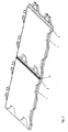
- FIG.1 . Fig.2 and Figure 3 a first embodiment of the plate according to the invention together with the plate-shaped carrier and FIGS. 4 . 5 . 6 and 7 modified formations of the plate-shaped carrier.
- Fig.1 is a plate, such as a granite slab for laying floors, designated 1.
- a plate-shaped carrier 2 On the underside of the plate 1, a plate-shaped carrier 2 is attached, which has locking members for the production of a snap connection with a further carrier 2.
- the further carrier 2 also carries a plate, which is not shown for clarity.
- the locking members are formed by projections 3, which are formed on elastically deflectable arms 4, and recesses 5.
- the arms 4 pivoted elastically inwardly be and engage the projections 3 in the corresponding recesses 5. In this case, the elastic arms 4 are deflected in the plane of the plate 1.
- the plates 1 can also be joined together in a direction perpendicular to the plane of the plate by inserting the projections 3 of one carrier 2 in the direction of the arrow 7 from above into the corresponding recesses 5 of the other carrier 2, without any deflection the arms 4 comes as is in Fig. 2 is shown.
- the carrier 2 is shown in the starting position with normal lines and in the assembled position with thin lines and denoted by 2 '.
- the elastically deflectable arms 4 project beyond the edge of the plate 1, the recesses 5 being formed in a rigid part of the plate-shaped carrier 2, namely in a region within the plate outline.
- the plate-shaped carrier 2 has a projecting over the edge of the plate 1 strip-like area 8, which extends at two adjacent edges 9 and 10 of the plate 1 and on which also the protruding arms 4 are formed.
- a joint seal can be arranged or molded by an injection molding process, as in Figure 3 is shown. In this case, two plates 1 are connected to each other and it can be seen that between the two plates 1 in the region 8, a gap is formed, which can be closed by a joint seal 17.
- the joint seal 17 can be used in this case when laying the plate in the appropriate joints.
- the joint seal is already factory-connected to the projecting portion 8 of the plate-shaped carrier 2 and / or with the edge 9 or 10 of the plate 1, wherein preferably the joint seal 17 is injection-molded or foamed by an injection molding process.
- arms 4 of the plate-shaped support 2 are arranged at an angle of 45 ° to the edge of the plate 1, so that a corresponding 45 ° -Fü deung according to the arrow 6 is favored.
- the arms 4 arranged in pairs, wherein the two arms 4 of a pair in mutually opposite directions directed projections 3 have. At two adjacent sides of the plate-shaped carrier 2 in each case two pairs of two arms 4 are arranged.
- the protruding arms 4 are arranged not only on two adjacent sides of the carrier 2 but on all sides, wherein corresponding recesses 5 are arranged on each side.
- the orientation of the plate 1 can be freely selected when joining with identically constructed plates.
- the resilient arms 11 of the plate-shaped carrier 2 are arranged in a region within the Plattenumrisses and there are the rigid locking members with the projections 12 on rigid parts 13 of the plate-shaped support 2 is formed.
- the projections 12 engage in corresponding recesses 14 of the elastically deflectable arms 11 a.
- the resilient arms are provided with projections or recesses.
- the projections are arranged on regions projecting beyond the plate edge or within the plate outline.
- both a male locking member 15 and a female locking member 16 are arranged, so that the orientation of the plate 1 can be freely selected when assembled with identically constructed plates. This is especially true of Advantage if certain structures or patterns applied to the plate surface are to be taken into consideration.
Abstract
Description
Die Erfindung betrifft eine Platte zur Verlegung auf Böden, Wänden, Decken, Fassaden oder dgl. im Innen- und Außenbereich, mit Verriegelungsgliedern, welche mit Verriegelungsgliedern benachbarter Platten zur Herstellung einer Schnappverbindung zwischen denselben zusammenwirken, wobei die Verriegelungsglieder wenigstens einen Vorsprung oder eine Ausnehmung umfassen und mit einem an der Unterseite der Platte angebrachten plattenförmigen Träger verbunden oder an diesem angeformt sind.The invention relates to a board for laying on floors, walls, ceilings, facades or the like. In the interior and exterior, with locking members which cooperate with locking members of adjacent plates for making a snap connection between them, wherein the locking members comprise at least one projection or a recess and are connected to or attached to a plate-shaped support attached to the underside of the plate.
Die Erfindung betrifft weiters einen plattenförmigen Träger zur Anbringung an der Unterseite einer Platte.The invention further relates to a plate-shaped carrier for attachment to the underside of a plate.
Auf Böden, Wänden, Decken, Fassaden und dgl. verlegbare Platten, wie beispielsweise Steinplatten, Keramikplatten, Holzplatten, Parkettplatten, Laminatplatten, Dekorplatten, Teppichfliesen und Glasfliesen, werden auf herkömmliche Art und Weise z.B. mit Hilfe eines Klebers am jeweiligen Untergrund befestigt und gegebenenfalls die Fugen mit einer Fugenmasse ausgefüllt. Diese Art der Verlegung weist jedoch einige Nachteile auf. Für das Verlegen der Platten sind fundierte Handwerkerkenntnisse erforder-lich, wobei kleine Fehler im Zuge des Verlegens der Platten, wie unregelmäßige Abstände, ungleichmäßiges Auftragen des Klebers etc., sich stark störend auswirken. Kleine Unebenheiten des Untergrundes und vor allem ein ungleichmäßiges Auftragen des Klebers und die dadurch hervorgerufenen Hohlräume unterhalb der Platte können bei Belastung der Platten zu einem Bruch der sel-ben führen. Weiters ist es nicht möglich bereits verlegte Platten zerstörungsfrei zu demontieren. Genau so wenig ist es möglich einzelne Platten mit geringem Aufwand auszutauschen.Floors, walls, ceilings, facades, and the like, such as flagstones, ceramic tiles, wooden panels, parquet panels, laminate panels, decorative panels, carpet tiles, and glass tiles are conventionally formed into e.g. fastened with the help of an adhesive to the respective substrate and, if necessary, filled the joints with a grout. However, this type of installation has some disadvantages. For the installation of the panels sound craftsmanship skills are required, with small errors in the course of laying the panels, such as irregular distances, uneven application of the adhesive, etc., have a strong disruptive effect. Small unevenness of the surface and above all an uneven application of the adhesive and the cavities caused thereby below the plate can lead to a break of the same when the plates are loaded. Furthermore, it is not possible to disassemble already laid plates non-destructive. Just as little is it possible to exchange individual plates with little effort.
Aus diesem Grund sind bereits Verlegesysteme für Platten der eingangs genannten Art bekannt geworden, bei welchen mit den Platten Verriegelungsglieder verbunden sind, mit deren Hilfe Schnappverbindungen zu benachbarten Platten hergestellt werden können, wobei die Verriegelungsglieder wenigstens einen Vorsprung oder eine Ausnehmung umfassen. So ist beispielsweise aus der
Die
Die
Die
Aus de
Auch der
Schließlich zeigt die
Die vorliegende Erfindung zielt nun darauf ab, eine Schnappverbindung zwischen den eingangs genannten Platten zu schaffen, welche eine größtmögliche Flexibilität hinsichtlich der Fügerichtung sicherstellt, wobei zumindest ein Zusammenfügen in einer Richtung parallel zur Plattenebene ermöglicht werden soll. Darüber hinaus sollen die Verriegelungskräfte im Vergleich zu den bekannten Verlegesystemen erhöht werden, sodass nicht nur Bodenbelege sondern auch Wandverkleidungen hergestellt werden können, bei welchen die Schnappverbindung zusätzlich durch das Eigengewicht der zu verlegenden Platten beansprucht wird.The present invention now aims to provide a snap connection between the plates mentioned above, which ensures the greatest possible flexibility in terms of joining direction, at least one assembly should be made possible in a direction parallel to the plane of the plate. In addition, the locking forces are to be increased in comparison to the known installation systems, so that not only floor coverings but also wall coverings can be produced in which the snap connection is additionally claimed by the weight of the plates to be laid.
Zur Lösung dieser Aufgabe besteht die Erfindung ausgehend von Platten der eingangs genannten Gattung mit Verriegelungsgliedern, welche wenigstens einen Vorsprung oder eine Ausnehmung umfassen, darin, dass der Vorsprung bzw. die Ausnehmung an wenigstens einem in der Ebene der Platte elastisch auslenkbaren Arm ausgebildet ist, sodass die Schnappverbindung durch Auslenken des Arms und anschließendes Einrasten der Verriegelungsglieder herstellbar ist. Dadurch, dass die Auslenkung des die Schnappverbindung ermöglichenden elastisch auslenkbaren Armes bei Zusammenfügen der Platten in der Ebene der Platte erfolgt, sind größere Ausweichbewegungen des auslenkbaren Arms möglich sodass die einander in der Verriegelungslage hintergreifenden Vorsprünge bzw. Ausnehmungen entsprechend größer ausgebildet werden können. Daraus folgt, dass die Schnappverbindung größere Verriegelungskräfte aufnehmen kann und ein stabilerer Verbund der Platten gewährleistet, ist. Im Gegensatz dazu ist bei einem System, bei welchem die Auslenkung der Schnappelemente in senkrechter Richtung zur Plattenebene erfolgt, auf Grund der zu erreichenden geringen Bauhöhe und der dadurch bedingten geringen Platzverhältnisse eine Auslenkung nur in geringem Maße möglich.To achieve this object, the invention, starting from plates of the type mentioned with locking members, which comprise at least one projection or a recess in that the projection or the recess is formed on at least one in the plane of the plate elastically deflectable arm, so the snap connection by deflecting the arm and subsequent engagement of the locking members can be produced. The fact that the deflection of the snap connection enabling elastically deflectable arm takes place when joining the plates in the plane of the plate, larger evasive movements of the deflectable arm are possible so that the engaging behind each other in the locking position projections or recesses can be made correspondingly larger. It follows that the snap connection can accommodate greater locking forces and ensures a more stable composite of the plates is. In contrast, in a system in which the deflection of the snap elements in the direction perpendicular to the plate plane, Due to the low height to be achieved and the consequent small space a deflection only to a small extent possible.
Als primäre Fügerichtung für die erfindungsgemäßen Platten ergibt sich eine Richtung parallel zur Plattenebene, sodass der zu verlegende Untergrund als Führungshilfe beim Ineinanderstecken der Platte dienen kann. Gleichzeitig ist jedoch durch die erfindungsgemäße Ausbildung ein Zusammenfügen in einer Weise möglich, bei welcher die Vorsprünge und Ausnehmungen der Verriegelungsglieder nicht durch Einschnappen in Eingriff miteinander gebracht werden, sondern ähnlich einem Puzzlespiel durch Einführen des Vorsprungs in senkrechter Richtung zur Plattenebene in die entsprechende Ausnehmung, wobei keine Auslenkung des elastischen Arms erfolgt. Dadurch kann bei Bedarf auch ein Auflegen von Platten in senkrechter Richtung zur Plattenebene erfolgen, sodass ein den Grundriß der Platte übersteigender Freiraum nicht benötigt wird.As a primary joining direction for the plates according to the invention, a direction results parallel to the plane of the plate, so that the substrate to be laid can serve as a guide when nesting the plate. At the same time, however, by the inventive construction joining in a manner possible in which the projections and recesses of the locking members are not brought into engagement with each other by snapping, but similar to a puzzle by inserting the projection in the direction perpendicular to the plate plane in the corresponding recess, said no deflection of the elastic arm takes place. As a result, if required, also a laying of plates in the direction perpendicular to the plane of the plate, so that the plan of the plate above free space is not needed.
Gemäß der Erfindung ist der elastisch auslenkbare Arm an der Unterseite der Platte angebracht, wobei der elastisch auslenkbare Arm mit einem an der Unterseite der Platte angebrachten plattenförmigen Träger verbunden oder an diesem angeformt ist. Bei dieser Ausbildung ist somit ein plattenförmiger Träger vorgesehen, auf welchen die zu verlegende Platte geklebt werden kann, sodass aufwändige Bearbeitungen der Platte selbst unterbleiben können. Der plattenförmige Träger und die mit diesem verbundenen oder an diesem angeformten Verriegelungsglieder, und insbesondere die elastisch auslenkbaren Arme, könnnen daher unabhängig von der Beschaffenheit des Materials und der Form der Platte aus einem geeigneten Material hergestellt werden, welches eine ausreichende Elastizität der Verriegelungsglieder und gleichzeitig eine ausreichende Stabilität der zu erzielenden Schnappverbindung sicherstellt.According to the invention, the elastically deflectable arm is attached to the underside of the plate, wherein the elastically deflectable arm is connected to or integrally formed with a plate-shaped support attached to the underside of the plate. In this embodiment, a plate-shaped support is thus provided, on which the plate to be laid can be glued, so that elaborate processing of the plate itself can be omitted. The plate-shaped support and the associated therewith or molded thereto locking members, and in particular the elastically deflectable arms, therefore, regardless of the nature of the material and the shape of the plate can be made of a suitable material, which has sufficient elasticity of the locking members and at the same time ensures sufficient stability of the snap connection to be achieved.
Der elastische Träger kann in einem eigenen Produktionsschritt hergestellt und beispielsweise mit der Unterseite der Platte verklebt werden. Bevorzugt ist erfindungsgemäß vorgesehen, dass der Träger an die Unterseite der Platte angeformt, angeschäumt oder angespritzt ausgebildet ist. Dadurch wird eine besonders einfache und kostensparende Herstellung ermöglicht, wobei lediglich Sorge dafür getragen werden muss, dass die elastisch auslenkbaren Bereiche des plattenförmigen Trägers nicht derart mit der Platte verbunden werden, dass eine Relativbewegung verhindert wird.The elastic carrier can be produced in a separate production step and glued, for example, with the underside of the plate. Preferably, the invention provides that the carrier is integrally formed, foamed or molded on the underside of the plate. As a result, a particularly simple and cost-saving production is made possible, whereby only care must be taken that the elastically deflectable areas of the plate-shaped carrier are not connected to the plate in such a way that a relative movement is prevented.
Die mit wenigstens einem Vorsprung oder einer Ausnehmung versehenen elastisch auslenkbaren Arme, können in verschiedenster Weise angeordnet werden und es ist beispielsweise möglich, dass sie über den Rand der Platte vorragend ausgebildet sind, wie dies einer bevorzugten Ausbildung der erfindungsgemäßen Platte entspricht. Der über den Rand der Platte vorragende Arm wirkt hierbei mit einem entsprechenden Gegenstück an einer benachbarten Platte zusammen, wobei das Gegenstück von einem starren Teil des plattenförmigen Trägers gebildet werden kann, welcher sich innerhalb des Grundrisses der Platte befindet. Die Anordnung von beweglichen Verriegelungsgliedern, welche über den Rand der Platte vorragen und von starren Verriegelungsgliedern, welche unterhalb der Platte und innerhalb des Grundrisses der Platte angeordnet sind, hat hierbei den Vorteil, dass oben erwähnte Problematik der freien Beweglichkeit von elastischen Armen relativ zur Platte nicht mehr auftritt. Da nun keine mit der Unterseite der Platte in Berührung stehende Bereiche des plattenförmigen Trägers benötigt werden, welche frei beweglich sein sollen, kann der plattenförmige Träger unmittelbar auf die Unterseite der zu verlegenden Platte mit Hilfe einens Spritzgußverfahrens angeformt werden, wodurch die Herstellungskosten wesentlich gesenkt werden können.The elastically deflectable arms provided with at least one projection or recess can be arranged in a great variety of ways and it is possible, for example, for them to be projecting beyond the edge of the plate, as corresponds to a preferred embodiment of the plate according to the invention. The protruding over the edge of the plate arm here cooperates with a corresponding counterpart on an adjacent plate, the counterpart can be formed by a rigid part of the plate-shaped support, which is located within the floor plan of the plate. The arrangement of movable locking members projecting beyond the edge of the plate and of rigid locking members located below the plate and within the outline of the plate has the advantage that the above-mentioned problem of free mobility of elastic arms relative to the plate does not exist more occurs. Since now no standing with the underside of the plate in contact areas of the plate-shaped support are to be freely movable, the plate-shaped support can be molded directly on the underside of the plate to be laid by means of an injection molding process, whereby the manufacturing cost can be significantly reduced ,
Gemäß einer anderen Ausbildung der erfindungsgemäßen Platte ist es jedoch auch denkbar, dass elastisch auslenkbare Arme unter der Platte innerhalb des Plattenumrisses angeordnet sind, wobei das jeweilige elastisch auslenkbare freie Ende dieser Arme zu einer Kante der Platte weist.According to another embodiment of the plate according to the invention, it is also conceivable that elastically deflectable arms are arranged under the plate within the Plattenumrisses, wherein the respective elastically deflectable free end of these arms facing an edge of the plate.
Um ein universelles Verlegesystem zu schaffen, bei welchem jede Platten an beliebigen Stellen innerhalb des Plattenrasters angeordnet werden kann, ist die Ausbildung bevorzugt derart getroffen, dass elastische auslenkbare Arme von lediglich zwei einander benachbarten Kanten der Platte vorragend oder zu diesen weisend angeordnet sind. Hierbei sind also zwei Seiten einer viereckigen Platte mit männlichen Verriegelungsgliedern und die anderen zwei Seiten der Platte mit weiblichen Verriegelungsgliedern versehen. Bei dieser Ausbildung ist die Orientierung einer Platte relativ zu den benachbarten Platten vorgegeben, da jeweils ein männliches mit einem weiblichen Verriegelungsglied verbunden werden muss. Bei Platten, welche eine Struktur bzw. ein Muster aufweisen, ist es jedoch wünschenswert eine viereckige Platte auch um 90°, 180° oder 370° verdreht anzuordnen. Zu diesem Zweck ist die Erfindung mit Vorteil darart weitergebildet, dass die Platte an jeder ihrer Kanten jeweils wenigstens einen von dieser Kante vorragenden oder zu dieser Kante weisenden elastisch auslenkbaren Arm und wenigstens ein mit den elastisch auslenkbaren Armen einer benachbarten Platte zusammenwirkender starres Verriegelungsglied aufweist. Dabei ist jede Kante mit einem männlichen und einem weiblichen Verriegelungsglied versehen, sodass die höchstmögliche Flexibilität gewährleistet ist.In order to provide a universal installation system in which each panel can be placed anywhere within the panel grid, the formation is preferably made such that resilient deflectable arms are projecting from or facing only two adjacent edges of the panel. In this case, therefore, two sides of a square plate with male locking members and the other two sides of the plate are provided with female locking members. In this embodiment, the orientation of a plate is predetermined relative to the adjacent plates, since in each case a male must be connected to a female locking member. In the case of plates which have a structure or a pattern, however, it is desirable to arrange a quadrangular plate also rotated by 90 °, 180 ° or 370 °. For this purpose, the invention is further developed with advantage such that the plate has at each of its edges at least one protruding from this edge or facing this edge elastically deflectable arm and at least one cooperating with the elastically deflectable arms of an adjacent plate rigid locking member. Each edge is provided with a male and a female locking member, so that the highest possible flexibility is guaranteed.
Um eine möglichst stabile Schnappverbindung herzustellen ist die Ausbildung bevorzugt derart getroffen, dass elastisch auslenkbare Arme paarweise mit in zueinander entgegengesetzte Richtungen gerichteten Vorsprüngen oder Ausnehmungen angeordnet sind.In order to produce the most stable snap connection, the design is preferably such that elastically deflectable arms are arranged in pairs with projections or recesses directed in mutually opposite directions.
Wie bereits erwähnt, verläuft die primäre Fügerichtung der erfindungsgemäßen Platten parallel zur Plattenebene. Nach der Verlegung einer ersten Reihe von Platten, muss nach Beginn der zweiten Reihe jede weitere zu verlegende Platte in der Plattenebenen unter Einhaltung einer Fügerichtung von 45° zu den Kanten der benachbarten Platten verlegt werden. Um dies zu erleichtern ist die Ausbildung mit Vorteil derart getroffen, dass die elastisch auslenkbaren Arme mit einer Seitenkante der Platte einen Winkel von 35° bis 55°, vorzugsweise 45°, einschließen.As already mentioned, the primary joining direction of the plates according to the invention runs parallel to the plate plane. After laying a first row of panels, after the beginning of the second row, each additional panel to be laid must be in the panel levels, observing a joining direction of 45 ° to the edges the adjacent panels are laid. To facilitate this, the training is advantageously made such that the elastically deflectable arms with an edge of the plate at an angle of 35 ° to 55 °, preferably 45 °, include.
Um in einfacher Weise eine Fugendichtung bereitzustellen ist mit Vorteil mit wenigstens zwei einander benachbarten Kanten der Platte und/oder mit einem über wenigstens zwei einander benachbarten Rändern der Platte vorragenden Bereich des plattenförmigen Trägers eine Fugendichtung verbunden, insbesondere angespritzt oder angeschäumt. Die Fugendichtung kann hierbei bei Zusammenfügen der Platten durch die Verriegelungskräfte etwas zusammengedrückt werden, sodass eine vollständige Abdichtung gelingt. Die Fugendichtung kann hierbei unmittelbar an einen über den Rand der Platte vorstehenden Bereich des plattenartigen Trägers durch Spritzgußverfahren angebracht werden, sodass keine gesonderten Stege, Randprofile oder dgl. benötigt werden, in welche Dichtungslippen eingesteckt werden müssen.To provide a joint seal in a simple manner is advantageously connected to at least two adjacent edges of the plate and / or with a projecting over at least two adjacent edges of the plate portion of the plate-shaped support a joint seal, in particular molded or foamed. The joint seal can in this case be slightly compressed by joining the plates by the locking forces, so that a complete seal succeeds. The joint seal can in this case be applied directly to an over the edge of the plate projecting portion of the plate-like support by injection molding, so that no separate webs, edge profiles or the like. Are needed in which sealing lips must be inserted.
Zur Lösung der eingangs genannten Aufgabe besteht die Erfindung auch in einem plattenförmigen Träger mit den Merkmalen des Anspruchs 11.To achieve the object mentioned above, the invention also consists in a plate-shaped carrier with the features of
Die Erfindung wird nachfolgend anhand von in der Zeichnung dargestellten Ausführungsbeispielen näher erläutert. In dieser zeigen
In
Bei Bedarf können die Platten 1 jedoch auch in senkrechter Richtung zur Plattenebene aneinander gefügt werden, indem die Vorsprünge 3 des einen Trägers 2 in Richtung des Pfeiles 7 von oben in die entsprechenden Ausnehmungen 5 des anderen Trägers 2 eingeführt werden, ohne dass es zu einer Auslenkung der Arme 4 kommt, wie dies in
Bei der Ausbildung gemäß den
Bei der Darstellung gemäß
Bei der Darstellung gemäß
Bei der Ausbildung gemäß
Bei der Ausbildung gemäß
Claims (16)
- A plate to be laid on floors, walls, ceilings, facades or the like, both inside and outside, which plate comprises locking members which cooperate with locking members of neighbouring plates (1) to produce a snap connection between the same, said locking members including at least one projection (3, 12) or recess (5, 14) and being connected with, or formed to, a plate-shaped carrier (2) attached to the lower side of the plate (1), characterized in that said projection (3, 12) or recess (5, 14), respectively, is formed on at least one arm (4, 11) which is elastically deflectable in the plane of the plate (1), so that said snap connection is producible by a deflection of the arm and the subsequent engagement of the locking members.
- A plate according to claim 1, characterized in that the carrier (2) is formed, foamed or injection-moulded to the lower side of the plate (1).
- A plate according to claim 1 or 2, characterized in that elastically deflectable arms (4, 11) are designed to project beyond the edge of the plate (1).
- A plate according to 1, 2 or 3, characterized in that elastically deflectable arms (11) are arranged below the plate (1) within the plate contour, with the respectively elastically deflectable free ends of said arms (11) being oriented towards an edge of the plate (1).
- A plate according to any one of claims 1 to 4, characterized in that elastically deflectable arms (4, 11) are arranged to project from, or be oriented to, only two adjacent edges (9, 10) of the plate (1).
- A plate according to any one of claims 1 to 5, characterized in that the projection (3, 12) or recess (5, 14), respectively, formed on an elastically deflectable arm (4, 11) cooperates with a recess (5, 14) or projection (3, 12), respectively, formed on a rigid portion (13) of a neighbouring plate (1).
- A plate according to any one of claims 1 to 6, characterized in that the plate (1) on each of its edges comprises at least one elastically deflectable arm each projecting (4) from, or oriented (11) to, the respective edge, and at least one rigid locking member (13) cooperating with the elastically deflectable arms (4, 11) of a neighbouring plate (1).
- A plate according to any one of claims 1 to 7, characterized in that elastically deflectable arms (4, 11) are arranged in pairs, including projections (3, 12) or recesses (5, 14) oriented in relatively opposite directions.
- A plate according to any one of claims 1 to 8, characterized in that the elastically deflectable arms (4, 11) enclose an angle of 35° to 55°, preferably 45°, with a lateral edge of the plate (1).
- A plate according to any one of claims 1 to 9, characterized in that a joint seal (17) is connected, particularly injection-moulded or foamed, to at least two adjacent edges (9, 10) of the plate (1) and/or to a portion (8) of the plate-shaped carrier (2) projecting beyond at least two adjacent edges (9, 10) of the plate (1).
- A plate-shaped carrier for attachment to the lower side of a plate (1) to be laid on floors, walls, ceilings, facades or the like, both inside and outside, to which plate-shaped carrier locking members comprising at least one projection (3, 12) or recess (5, 14) are connected or formed, said locking members cooperating with locking members of neighbouring carriers (2) to produce a snap connection between the same, characterized in that said projection (3, 12) or recess (5, 14), respectively, is formed on at least one arm (4, 11) which is elastically deflectable in the plane of the plate (1), so that said snap connection is producible by a deflection of the arm and the subsequent engagement of the locking members, wherein the elastically deflectable arm (4, 11) encloses an angle of 35° to 55°, preferably 45°, with a lateral edge of the carrier (2).
- A plate-shaped carrier according to claim 11, characterized in that elastically deflectable arms (4, 11) are arranged to project from, or be oriented to, only two adjacent edges (9, 10) of the plate-shaped carrier (2).
- A plate-shaped carrier according to claim 11 or 12, characterized in that the projection (3, 12) or recess (5, 14), respectively, formed on an elastically deflectable arm (4, 11) cooperates with a recess (5, 14) or projection (3, 12), respectively, formed on a rigid portion (13) of a neighbouring carrier (2).
- A plate-shaped carrier according to claim 11, 12 or 13, characterized in that the carrier (2) on each of its edges comprises at least one elastically deflectable arm each projecting (4) from, or oriented (11) to, the respective edge, and at least one rigid locking member (13) cooperating with the elastically deflectable arms (4, 11) of a neighbouring carrier (2).
- A plate-shaped carrier according to any one of claims 11 to 14, characterized in that elastically deflectable arms (4, 11) are arranged in pairs, including projections (3, 12) or recesses (5, 14) oriented in relatively opposite directions.
- A plate-shaped carrier according to any one of claims 11 to 15, characterized in that a joint seal (17) is connected, particularly injection-moulded or foamed, to a portion (8) of the plate-shaped carrier (2) projecting beyond at least two neighbouring edges (9, 10) of the plate (1).
Priority Applications (1)
| Application Number | Priority Date | Filing Date | Title |
|---|---|---|---|
| AT04737369T ATE424515T1 (en) | 2003-07-07 | 2004-07-05 | BOARD FOR LAYING ON FLOORS, WALLS, CEILINGS, FACADES OR THE LIKE |
Applications Claiming Priority (2)
| Application Number | Priority Date | Filing Date | Title |
|---|---|---|---|
| AT4782003 | 2003-07-07 | ||
| PCT/AT2004/000239 WO2005003574A1 (en) | 2003-07-07 | 2004-07-05 | Tile for application to floors, walls, ceilings, facades, or similar |
Publications (2)
| Publication Number | Publication Date |
|---|---|
| EP1642036A1 EP1642036A1 (en) | 2006-04-05 |
| EP1642036B1 true EP1642036B1 (en) | 2009-03-04 |
Family
ID=40427672
Family Applications (1)
| Application Number | Title | Priority Date | Filing Date |
|---|---|---|---|
| EP04737369A Active EP1642036B1 (en) | 2003-07-07 | 2004-07-05 | Tile for application to floors, walls, ceilings, facades, or similar |
Country Status (4)
| Country | Link |
|---|---|
| EP (1) | EP1642036B1 (en) |
| AT (1) | ATE424515T1 (en) |
| DE (1) | DE502004009090D1 (en) |
| WO (1) | WO2005003574A1 (en) |
Families Citing this family (15)
| Publication number | Priority date | Publication date | Assignee | Title |
|---|---|---|---|---|
| CN100425784C (en) * | 2005-03-11 | 2008-10-15 | 罗生权 | Wood floor board with plastic keel |
| EP1934417B1 (en) | 2005-10-03 | 2012-05-23 | Tarkett SAS | Kit for the construction of a covering surface |
| WO2007038989A1 (en) * | 2005-10-05 | 2007-04-12 | Penrose Parkettgestaltung Gmbh | Parquet area, parquet element, and combination of parquet elements |
| GB0520309D0 (en) * | 2005-10-06 | 2005-11-16 | Specialised Panel Products Ltd | Improvements in and relating to flooring |
| ES2310100B1 (en) * | 2006-07-31 | 2009-11-10 | Insca Internacional, S.L. | PARQUET. |
| DE102006027982B3 (en) * | 2006-06-14 | 2007-12-06 | Fritz Egger Gmbh & Co. | Component, preferably for the covering of floors, walls and ceilings, and method for its production |
| CN101523001B (en) * | 2006-10-03 | 2012-08-15 | 波斯查彻天然石料厂有限责任两合公司 | Plate for laying on floors, walls, ceilings, facades or the like |
| ATE544920T1 (en) * | 2006-10-05 | 2012-02-15 | Poschacher Natursteinwerke Gmbh & Co Kg | A METHOD FOR FIXING PLATES TO A SUPPORT AND A PLATE HAVING A DEVICE FOR SETTING THE SAME TO A SUPPORT |
| WO2008040041A1 (en) * | 2006-10-05 | 2008-04-10 | Poschacher Natursteinwerke Gmbh & Co Kg | Plate for laying especially on floors, walls, ceilings, façades or the like |
| CN101532331A (en) * | 2007-07-30 | 2009-09-16 | 诺瓦利斯股份有限公司 | Floor covering with interlocking design |
| JP2013515878A (en) * | 2009-12-23 | 2013-05-09 | ホンコン メイ リ シェン フローリング カンパニー リミテッド | Easy to lay flooring |
| WO2016001886A1 (en) * | 2014-07-04 | 2016-01-07 | Dessington, Antony John Lee | A support arrangement for a structural lining |
| GB201721514D0 (en) * | 2017-12-20 | 2018-01-31 | Winward Advantage Ltd | A set of parts and apparatus assembled therefrom |
| WO2023034261A1 (en) * | 2021-08-31 | 2023-03-09 | Plastic Safety Systems, Inc. | Temporary walkway system with modular tiles interlocking in three-dimensions |
| WO2023200367A1 (en) * | 2022-04-12 | 2023-10-19 | Денис САГИДУЛЛИН | Light-reflecting decorative panel |
Family Cites Families (8)
| Publication number | Priority date | Publication date | Assignee | Title |
|---|---|---|---|---|
| GB589635A (en) * | 1945-03-14 | 1947-06-25 | Laurence Victor Hughes | Improvements in or relating to floor-covering and the like material |
| US3657852A (en) * | 1969-09-15 | 1972-04-25 | Walter J Worthington | Floor tiles |
| DE29703123U1 (en) * | 1997-02-21 | 1997-06-05 | Emt Werkzeug Und Formenbau Gmb | Flooring |
| DE20107338U1 (en) * | 2001-04-28 | 2001-06-28 | Schulze Zuralst Karl | Flexible floor covering system |
| DE20114787U1 (en) * | 2001-09-06 | 2001-11-29 | Debolon Dessauer Bodenbelaege | Flat-shaped covering element for display surfaces in need of covering, which is designed as a partial surface and is ready for installation |
| ES2246746T1 (en) * | 2001-11-28 | 2006-03-01 | Meyer, Hans | PLACEMENT SYSTEM FOR TILES. |
| WO2003093605A1 (en) * | 2002-05-03 | 2003-11-13 | Westminster Products Pty Ltd | Interconnectable tiles and structures made therefrom |
| DE10243196B4 (en) * | 2002-09-18 | 2007-03-22 | Kaindl Flooring Gmbh | Panels with connection bracket |
-
2004
- 2004-07-05 DE DE502004009090T patent/DE502004009090D1/en active Active
- 2004-07-05 WO PCT/AT2004/000239 patent/WO2005003574A1/en active Search and Examination
- 2004-07-05 EP EP04737369A patent/EP1642036B1/en active Active
- 2004-07-05 AT AT04737369T patent/ATE424515T1/en not_active IP Right Cessation
Also Published As
| Publication number | Publication date |
|---|---|
| DE502004009090D1 (en) | 2009-04-16 |
| ATE424515T1 (en) | 2009-03-15 |
| EP1642036A1 (en) | 2006-04-05 |
| WO2005003574A1 (en) | 2005-01-13 |
Similar Documents
| Publication | Publication Date | Title |
|---|---|---|
| EP3298212B1 (en) | Covering of rectangular or square panels laid to form an assembly | |
| EP1642036B1 (en) | Tile for application to floors, walls, ceilings, facades, or similar | |
| DE10337352B3 (en) | Device for connecting and locking of especially floor panels has insert for fitting in slots in side edges of panels and provided with at least one spring lip orientated towards upper side or lower side of panel | |
| EP3321448B1 (en) | Panel | |
| EP1379739B1 (en) | Construction kit consisting of panel-shaped elements and connecting elements | |
| DE102005002297A1 (en) | Tile-shaped building parts e.g. laminated floor tiles, joint, has devices for horizontal and vertical interlocking, which is provided along part`s leading edges formed independent of elasticity of materials with which parts are made | |
| WO2006032378A1 (en) | Panel in particular floor panel | |
| WO2001051732A1 (en) | Panel element | |
| WO2001002670A1 (en) | Panel and panel fastening system | |
| EP1490566A1 (en) | Panel and interlocking system for panels | |
| DE202007018998U1 (en) | Connection for plate-shaped components | |
| DE102007019786A1 (en) | Connection for plate shaped elements, particularly floor panels, has lengthwise and front edge bolting mechanism that is formed for vertical bolting, and bolting cam in bolting position obstructs movement of spring guide toward unblocking | |
| WO2007014665A1 (en) | Floor covering | |
| AT413840B (en) | PLATE FOR LAYING ON FLOORS, WALLS, CEILINGS, FAÇADES OR DGL. | |
| WO2008040039A1 (en) | Plate for laying on floors, walls, ceilings, façades or the like | |
| EP2845965B1 (en) | Mounting of planks to a substructure | |
| EP3372749B1 (en) | Floorboard system | |
| EP0149443B1 (en) | Clamping connection between double-walled panels provided with cross-beams and a profile, especially for small greenhouses | |
| DE19640128A1 (en) | Floor lining for industrial constructions | |
| EP3748103B1 (en) | Floor covering with at least one connecting element | |
| WO2006002818A1 (en) | Surface coating | |
| AT9957U1 (en) | PLATES FOR LAYING ON FLOORS, WALLS, CEILINGS, FAÇADES OR DGL. | |
| EP3372750B1 (en) | Floorboard system | |
| DE19823357A1 (en) | Wall tile with spacers | |
| WO2004076775A1 (en) | Coverings consisting of covering panels |
Legal Events
| Date | Code | Title | Description |
|---|---|---|---|
| PUAI | Public reference made under article 153(3) epc to a published international application that has entered the european phase |
Free format text: ORIGINAL CODE: 0009012 |
|
| 17P | Request for examination filed |
Effective date: 20060121 |
|
| AK | Designated contracting states |
Kind code of ref document: A1 Designated state(s): AT BE BG CH CY CZ DE DK EE ES FI FR GB GR HU IE IT LI LU MC NL PL PT RO SE SI SK TR |
|
| AX | Request for extension of the european patent |
Extension state: LT LV |
|
| RAX | Requested extension states of the european patent have changed |
Extension state: LT Payment date: 20060121 Extension state: LV Payment date: 20060121 |
|
| 17Q | First examination report despatched |
Effective date: 20080401 |
|
| GRAP | Despatch of communication of intention to grant a patent |
Free format text: ORIGINAL CODE: EPIDOSNIGR1 |
|
| GRAS | Grant fee paid |
Free format text: ORIGINAL CODE: EPIDOSNIGR3 |
|
| GRAA | (expected) grant |
Free format text: ORIGINAL CODE: 0009210 |
|
| AK | Designated contracting states |
Kind code of ref document: B1 Designated state(s): AT BE BG CH CY CZ DE DK EE ES FI FR GB GR HU IE IT LI LU MC NL PL PT RO SE SI SK TR |
|
| AX | Request for extension of the european patent |
Extension state: LT LV |
|
| REG | Reference to a national code |
Ref country code: GB Ref legal event code: FG4D Free format text: NOT ENGLISH |
|
| REG | Reference to a national code |
Ref country code: CH Ref legal event code: EP |
|
| REG | Reference to a national code |
Ref country code: IE Ref legal event code: FG4D Free format text: LANGUAGE OF EP DOCUMENT: GERMAN |
|
| REF | Corresponds to: |
Ref document number: 502004009090 Country of ref document: DE Date of ref document: 20090416 Kind code of ref document: P |
|
| PG25 | Lapsed in a contracting state [announced via postgrant information from national office to epo] |
Ref country code: FI Free format text: LAPSE BECAUSE OF FAILURE TO SUBMIT A TRANSLATION OF THE DESCRIPTION OR TO PAY THE FEE WITHIN THE PRESCRIBED TIME-LIMIT Effective date: 20090304 Ref country code: SI Free format text: LAPSE BECAUSE OF FAILURE TO SUBMIT A TRANSLATION OF THE DESCRIPTION OR TO PAY THE FEE WITHIN THE PRESCRIBED TIME-LIMIT Effective date: 20090304 Ref country code: NL Free format text: LAPSE BECAUSE OF FAILURE TO SUBMIT A TRANSLATION OF THE DESCRIPTION OR TO PAY THE FEE WITHIN THE PRESCRIBED TIME-LIMIT Effective date: 20090304 |
|
| NLV1 | Nl: lapsed or annulled due to failure to fulfill the requirements of art. 29p and 29m of the patents act | ||
| LTIE | Lt: invalidation of european patent or patent extension |
Effective date: 20090304 |
|
| PG25 | Lapsed in a contracting state [announced via postgrant information from national office to epo] |
Ref country code: SE Free format text: LAPSE BECAUSE OF FAILURE TO SUBMIT A TRANSLATION OF THE DESCRIPTION OR TO PAY THE FEE WITHIN THE PRESCRIBED TIME-LIMIT Effective date: 20090604 Ref country code: PL Free format text: LAPSE BECAUSE OF FAILURE TO SUBMIT A TRANSLATION OF THE DESCRIPTION OR TO PAY THE FEE WITHIN THE PRESCRIBED TIME-LIMIT Effective date: 20090304 |
|
| REG | Reference to a national code |
Ref country code: IE Ref legal event code: FD4D |
|
| PG25 | Lapsed in a contracting state [announced via postgrant information from national office to epo] |
Ref country code: IE Free format text: LAPSE BECAUSE OF FAILURE TO SUBMIT A TRANSLATION OF THE DESCRIPTION OR TO PAY THE FEE WITHIN THE PRESCRIBED TIME-LIMIT Effective date: 20090304 Ref country code: EE Free format text: LAPSE BECAUSE OF FAILURE TO SUBMIT A TRANSLATION OF THE DESCRIPTION OR TO PAY THE FEE WITHIN THE PRESCRIBED TIME-LIMIT Effective date: 20090304 Ref country code: CZ Free format text: LAPSE BECAUSE OF FAILURE TO SUBMIT A TRANSLATION OF THE DESCRIPTION OR TO PAY THE FEE WITHIN THE PRESCRIBED TIME-LIMIT Effective date: 20090304 Ref country code: PT Free format text: LAPSE BECAUSE OF FAILURE TO SUBMIT A TRANSLATION OF THE DESCRIPTION OR TO PAY THE FEE WITHIN THE PRESCRIBED TIME-LIMIT Effective date: 20090819 Ref country code: ES Free format text: LAPSE BECAUSE OF FAILURE TO SUBMIT A TRANSLATION OF THE DESCRIPTION OR TO PAY THE FEE WITHIN THE PRESCRIBED TIME-LIMIT Effective date: 20090615 |
|
| PG25 | Lapsed in a contracting state [announced via postgrant information from national office to epo] |
Ref country code: RO Free format text: LAPSE BECAUSE OF FAILURE TO SUBMIT A TRANSLATION OF THE DESCRIPTION OR TO PAY THE FEE WITHIN THE PRESCRIBED TIME-LIMIT Effective date: 20090304 Ref country code: SK Free format text: LAPSE BECAUSE OF FAILURE TO SUBMIT A TRANSLATION OF THE DESCRIPTION OR TO PAY THE FEE WITHIN THE PRESCRIBED TIME-LIMIT Effective date: 20090304 |
|
| REG | Reference to a national code |
Ref country code: HU Ref legal event code: AG4A Ref document number: E006099 Country of ref document: HU |
|
| PLBE | No opposition filed within time limit |
Free format text: ORIGINAL CODE: 0009261 |
|
| STAA | Information on the status of an ep patent application or granted ep patent |
Free format text: STATUS: NO OPPOSITION FILED WITHIN TIME LIMIT |
|
| PG25 | Lapsed in a contracting state [announced via postgrant information from national office to epo] |
Ref country code: DK Free format text: LAPSE BECAUSE OF FAILURE TO SUBMIT A TRANSLATION OF THE DESCRIPTION OR TO PAY THE FEE WITHIN THE PRESCRIBED TIME-LIMIT Effective date: 20090304 Ref country code: BG Free format text: LAPSE BECAUSE OF FAILURE TO SUBMIT A TRANSLATION OF THE DESCRIPTION OR TO PAY THE FEE WITHIN THE PRESCRIBED TIME-LIMIT Effective date: 20090604 |
|
| BERE | Be: lapsed |
Owner name: POSCHACHER NATURSTEINWERKE GMBH & CO KG Effective date: 20090731 |
|
| 26N | No opposition filed |
Effective date: 20091207 |
|
| PG25 | Lapsed in a contracting state [announced via postgrant information from national office to epo] |
Ref country code: MC Free format text: LAPSE BECAUSE OF NON-PAYMENT OF DUE FEES Effective date: 20090731 |
|
| REG | Reference to a national code |
Ref country code: CH Ref legal event code: PL |
|
| GBPC | Gb: european patent ceased through non-payment of renewal fee |
Effective date: 20090705 |
|
| PG25 | Lapsed in a contracting state [announced via postgrant information from national office to epo] |
Ref country code: CH Free format text: LAPSE BECAUSE OF NON-PAYMENT OF DUE FEES Effective date: 20090731 Ref country code: LI Free format text: LAPSE BECAUSE OF NON-PAYMENT OF DUE FEES Effective date: 20090731 |
|
| PG25 | Lapsed in a contracting state [announced via postgrant information from national office to epo] |
Ref country code: GB Free format text: LAPSE BECAUSE OF NON-PAYMENT OF DUE FEES Effective date: 20090705 |
|
| PG25 | Lapsed in a contracting state [announced via postgrant information from national office to epo] |
Ref country code: BE Free format text: LAPSE BECAUSE OF NON-PAYMENT OF DUE FEES Effective date: 20090731 |
|
| PG25 | Lapsed in a contracting state [announced via postgrant information from national office to epo] |
Ref country code: GR Free format text: LAPSE BECAUSE OF FAILURE TO SUBMIT A TRANSLATION OF THE DESCRIPTION OR TO PAY THE FEE WITHIN THE PRESCRIBED TIME-LIMIT Effective date: 20090605 |
|
| PG25 | Lapsed in a contracting state [announced via postgrant information from national office to epo] |
Ref country code: AT Free format text: LAPSE BECAUSE OF NON-PAYMENT OF DUE FEES Effective date: 20090705 |
|
| PG25 | Lapsed in a contracting state [announced via postgrant information from national office to epo] |
Ref country code: IT Free format text: LAPSE BECAUSE OF FAILURE TO SUBMIT A TRANSLATION OF THE DESCRIPTION OR TO PAY THE FEE WITHIN THE PRESCRIBED TIME-LIMIT Effective date: 20090304 |
|
| PG25 | Lapsed in a contracting state [announced via postgrant information from national office to epo] |
Ref country code: LU Free format text: LAPSE BECAUSE OF NON-PAYMENT OF DUE FEES Effective date: 20090705 |
|
| PG25 | Lapsed in a contracting state [announced via postgrant information from national office to epo] |
Ref country code: TR Free format text: LAPSE BECAUSE OF FAILURE TO SUBMIT A TRANSLATION OF THE DESCRIPTION OR TO PAY THE FEE WITHIN THE PRESCRIBED TIME-LIMIT Effective date: 20090304 |
|
| PG25 | Lapsed in a contracting state [announced via postgrant information from national office to epo] |
Ref country code: CY Free format text: LAPSE BECAUSE OF FAILURE TO SUBMIT A TRANSLATION OF THE DESCRIPTION OR TO PAY THE FEE WITHIN THE PRESCRIBED TIME-LIMIT Effective date: 20090304 |
|
| PGFP | Annual fee paid to national office [announced via postgrant information from national office to epo] |
Ref country code: HU Payment date: 20110712 Year of fee payment: 8 |
|
| PGFP | Annual fee paid to national office [announced via postgrant information from national office to epo] |
Ref country code: FR Payment date: 20120711 Year of fee payment: 9 Ref country code: DE Payment date: 20120629 Year of fee payment: 9 |
|
| PG25 | Lapsed in a contracting state [announced via postgrant information from national office to epo] |
Ref country code: HU Free format text: LAPSE BECAUSE OF NON-PAYMENT OF DUE FEES Effective date: 20120706 |
|
| REG | Reference to a national code |
Ref country code: FR Ref legal event code: ST Effective date: 20140331 |
|
| PG25 | Lapsed in a contracting state [announced via postgrant information from national office to epo] |
Ref country code: DE Free format text: LAPSE BECAUSE OF NON-PAYMENT OF DUE FEES Effective date: 20140201 |
|
| REG | Reference to a national code |
Ref country code: DE Ref legal event code: R119 Ref document number: 502004009090 Country of ref document: DE Effective date: 20140201 |
|
| PG25 | Lapsed in a contracting state [announced via postgrant information from national office to epo] |
Ref country code: FR Free format text: LAPSE BECAUSE OF NON-PAYMENT OF DUE FEES Effective date: 20130731 |