EP1641580B1 - Device for the production of thin powder layers, in particular at high temperatures, during a method involving the use of a laser on a material - Google Patents
Device for the production of thin powder layers, in particular at high temperatures, during a method involving the use of a laser on a material Download PDFInfo
- Publication number
- EP1641580B1 EP1641580B1 EP04767492A EP04767492A EP1641580B1 EP 1641580 B1 EP1641580 B1 EP 1641580B1 EP 04767492 A EP04767492 A EP 04767492A EP 04767492 A EP04767492 A EP 04767492A EP 1641580 B1 EP1641580 B1 EP 1641580B1
- Authority
- EP
- European Patent Office
- Prior art keywords
- powder
- cylinder
- mixture
- powders
- enclosure
- Prior art date
- Legal status (The legal status is an assumption and is not a legal conclusion. Google has not performed a legal analysis and makes no representation as to the accuracy of the status listed.)
- Active
Links
- 239000000843 powder Substances 0.000 title claims abstract description 135
- 239000000463 material Substances 0.000 title claims description 7
- 238000000034 method Methods 0.000 title description 6
- 238000004519 manufacturing process Methods 0.000 title description 2
- 239000000203 mixture Substances 0.000 claims abstract description 49
- 230000008021 deposition Effects 0.000 claims abstract description 25
- 238000003860 storage Methods 0.000 claims description 9
- 238000005056 compaction Methods 0.000 claims description 8
- 238000009413 insulation Methods 0.000 claims description 4
- 238000001033 granulometry Methods 0.000 claims 1
- 239000000919 ceramic Substances 0.000 abstract description 8
- 238000000151 deposition Methods 0.000 description 17
- 238000006073 displacement reaction Methods 0.000 description 11
- 238000005299 abrasion Methods 0.000 description 5
- 239000002184 metal Substances 0.000 description 5
- 239000002245 particle Substances 0.000 description 5
- 238000003892 spreading Methods 0.000 description 5
- 238000005245 sintering Methods 0.000 description 4
- VYPSYNLAJGMNEJ-UHFFFAOYSA-N Silicium dioxide Chemical compound O=[Si]=O VYPSYNLAJGMNEJ-UHFFFAOYSA-N 0.000 description 2
- 230000010339 dilation Effects 0.000 description 2
- 238000009499 grossing Methods 0.000 description 2
- 238000010438 heat treatment Methods 0.000 description 2
- 210000000056 organ Anatomy 0.000 description 2
- 238000007789 sealing Methods 0.000 description 2
- 230000006835 compression Effects 0.000 description 1
- 238000007906 compression Methods 0.000 description 1
- 238000005520 cutting process Methods 0.000 description 1
- 230000003247 decreasing effect Effects 0.000 description 1
- 238000010586 diagram Methods 0.000 description 1
- 238000009826 distribution Methods 0.000 description 1
- 230000000694 effects Effects 0.000 description 1
- 239000007789 gas Substances 0.000 description 1
- 230000005484 gravity Effects 0.000 description 1
- 238000007373 indentation Methods 0.000 description 1
- 238000002955 isolation Methods 0.000 description 1
- 238000012423 maintenance Methods 0.000 description 1
- 238000010309 melting process Methods 0.000 description 1
- 239000012071 phase Substances 0.000 description 1
- 238000007790 scraping Methods 0.000 description 1
- 239000000377 silicon dioxide Substances 0.000 description 1
- 239000007790 solid phase Substances 0.000 description 1
- 230000035882 stress Effects 0.000 description 1
- 230000008646 thermal stress Effects 0.000 description 1
- 238000003466 welding Methods 0.000 description 1
Images


Classifications
-
- B—PERFORMING OPERATIONS; TRANSPORTING
- B23—MACHINE TOOLS; METAL-WORKING NOT OTHERWISE PROVIDED FOR
- B23K—SOLDERING OR UNSOLDERING; WELDING; CLADDING OR PLATING BY SOLDERING OR WELDING; CUTTING BY APPLYING HEAT LOCALLY, e.g. FLAME CUTTING; WORKING BY LASER BEAM
- B23K26/00—Working by laser beam, e.g. welding, cutting or boring
- B23K26/34—Laser welding for purposes other than joining
-
- B—PERFORMING OPERATIONS; TRANSPORTING
- B22—CASTING; POWDER METALLURGY
- B22F—WORKING METALLIC POWDER; MANUFACTURE OF ARTICLES FROM METALLIC POWDER; MAKING METALLIC POWDER; APPARATUS OR DEVICES SPECIALLY ADAPTED FOR METALLIC POWDER
- B22F10/00—Additive manufacturing of workpieces or articles from metallic powder
- B22F10/20—Direct sintering or melting
- B22F10/28—Powder bed fusion, e.g. selective laser melting [SLM] or electron beam melting [EBM]
-
- B—PERFORMING OPERATIONS; TRANSPORTING
- B22—CASTING; POWDER METALLURGY
- B22F—WORKING METALLIC POWDER; MANUFACTURE OF ARTICLES FROM METALLIC POWDER; MAKING METALLIC POWDER; APPARATUS OR DEVICES SPECIALLY ADAPTED FOR METALLIC POWDER
- B22F12/00—Apparatus or devices specially adapted for additive manufacturing; Auxiliary means for additive manufacturing; Combinations of additive manufacturing apparatus or devices with other processing apparatus or devices
- B22F12/60—Planarisation devices; Compression devices
- B22F12/63—Rollers
-
- B—PERFORMING OPERATIONS; TRANSPORTING
- B22—CASTING; POWDER METALLURGY
- B22F—WORKING METALLIC POWDER; MANUFACTURE OF ARTICLES FROM METALLIC POWDER; MAKING METALLIC POWDER; APPARATUS OR DEVICES SPECIALLY ADAPTED FOR METALLIC POWDER
- B22F3/00—Manufacture of workpieces or articles from metallic powder characterised by the manner of compacting or sintering; Apparatus specially adapted therefor ; Presses and furnaces
- B22F3/004—Filling molds with powder
-
- B—PERFORMING OPERATIONS; TRANSPORTING
- B23—MACHINE TOOLS; METAL-WORKING NOT OTHERWISE PROVIDED FOR
- B23K—SOLDERING OR UNSOLDERING; WELDING; CLADDING OR PLATING BY SOLDERING OR WELDING; CUTTING BY APPLYING HEAT LOCALLY, e.g. FLAME CUTTING; WORKING BY LASER BEAM
- B23K35/00—Rods, electrodes, materials, or media, for use in soldering, welding, or cutting
- B23K35/02—Rods, electrodes, materials, or media, for use in soldering, welding, or cutting characterised by mechanical features, e.g. shape
- B23K35/0222—Rods, electrodes, materials, or media, for use in soldering, welding, or cutting characterised by mechanical features, e.g. shape for use in soldering, brazing
- B23K35/0244—Powders, particles or spheres; Preforms made therefrom
-
- B—PERFORMING OPERATIONS; TRANSPORTING
- B23—MACHINE TOOLS; METAL-WORKING NOT OTHERWISE PROVIDED FOR
- B23K—SOLDERING OR UNSOLDERING; WELDING; CLADDING OR PLATING BY SOLDERING OR WELDING; CUTTING BY APPLYING HEAT LOCALLY, e.g. FLAME CUTTING; WORKING BY LASER BEAM
- B23K35/00—Rods, electrodes, materials, or media, for use in soldering, welding, or cutting
- B23K35/02—Rods, electrodes, materials, or media, for use in soldering, welding, or cutting characterised by mechanical features, e.g. shape
- B23K35/0255—Rods, electrodes, materials, or media, for use in soldering, welding, or cutting characterised by mechanical features, e.g. shape for use in welding
-
- B—PERFORMING OPERATIONS; TRANSPORTING
- B29—WORKING OF PLASTICS; WORKING OF SUBSTANCES IN A PLASTIC STATE IN GENERAL
- B29C—SHAPING OR JOINING OF PLASTICS; SHAPING OF MATERIAL IN A PLASTIC STATE, NOT OTHERWISE PROVIDED FOR; AFTER-TREATMENT OF THE SHAPED PRODUCTS, e.g. REPAIRING
- B29C64/00—Additive manufacturing, i.e. manufacturing of three-dimensional [3D] objects by additive deposition, additive agglomeration or additive layering, e.g. by 3D printing, stereolithography or selective laser sintering
- B29C64/10—Processes of additive manufacturing
- B29C64/106—Processes of additive manufacturing using only liquids or viscous materials, e.g. depositing a continuous bead of viscous material
- B29C64/124—Processes of additive manufacturing using only liquids or viscous materials, e.g. depositing a continuous bead of viscous material using layers of liquid which are selectively solidified
- B29C64/129—Processes of additive manufacturing using only liquids or viscous materials, e.g. depositing a continuous bead of viscous material using layers of liquid which are selectively solidified characterised by the energy source therefor, e.g. by global irradiation combined with a mask
- B29C64/135—Processes of additive manufacturing using only liquids or viscous materials, e.g. depositing a continuous bead of viscous material using layers of liquid which are selectively solidified characterised by the energy source therefor, e.g. by global irradiation combined with a mask the energy source being concentrated, e.g. scanning lasers or focused light sources
-
- B—PERFORMING OPERATIONS; TRANSPORTING
- B22—CASTING; POWDER METALLURGY
- B22F—WORKING METALLIC POWDER; MANUFACTURE OF ARTICLES FROM METALLIC POWDER; MAKING METALLIC POWDER; APPARATUS OR DEVICES SPECIALLY ADAPTED FOR METALLIC POWDER
- B22F12/00—Apparatus or devices specially adapted for additive manufacturing; Auxiliary means for additive manufacturing; Combinations of additive manufacturing apparatus or devices with other processing apparatus or devices
- B22F12/22—Driving means
- B22F12/224—Driving means for motion along a direction within the plane of a layer
-
- B—PERFORMING OPERATIONS; TRANSPORTING
- B22—CASTING; POWDER METALLURGY
- B22F—WORKING METALLIC POWDER; MANUFACTURE OF ARTICLES FROM METALLIC POWDER; MAKING METALLIC POWDER; APPARATUS OR DEVICES SPECIALLY ADAPTED FOR METALLIC POWDER
- B22F12/00—Apparatus or devices specially adapted for additive manufacturing; Auxiliary means for additive manufacturing; Combinations of additive manufacturing apparatus or devices with other processing apparatus or devices
- B22F12/22—Driving means
- B22F12/226—Driving means for rotary motion
-
- B—PERFORMING OPERATIONS; TRANSPORTING
- B22—CASTING; POWDER METALLURGY
- B22F—WORKING METALLIC POWDER; MANUFACTURE OF ARTICLES FROM METALLIC POWDER; MAKING METALLIC POWDER; APPARATUS OR DEVICES SPECIALLY ADAPTED FOR METALLIC POWDER
- B22F12/00—Apparatus or devices specially adapted for additive manufacturing; Auxiliary means for additive manufacturing; Combinations of additive manufacturing apparatus or devices with other processing apparatus or devices
- B22F12/50—Means for feeding of material, e.g. heads
-
- B—PERFORMING OPERATIONS; TRANSPORTING
- B22—CASTING; POWDER METALLURGY
- B22F—WORKING METALLIC POWDER; MANUFACTURE OF ARTICLES FROM METALLIC POWDER; MAKING METALLIC POWDER; APPARATUS OR DEVICES SPECIALLY ADAPTED FOR METALLIC POWDER
- B22F12/00—Apparatus or devices specially adapted for additive manufacturing; Auxiliary means for additive manufacturing; Combinations of additive manufacturing apparatus or devices with other processing apparatus or devices
- B22F12/60—Planarisation devices; Compression devices
- B22F12/67—Blades
-
- B—PERFORMING OPERATIONS; TRANSPORTING
- B22—CASTING; POWDER METALLURGY
- B22F—WORKING METALLIC POWDER; MANUFACTURE OF ARTICLES FROM METALLIC POWDER; MAKING METALLIC POWDER; APPARATUS OR DEVICES SPECIALLY ADAPTED FOR METALLIC POWDER
- B22F2999/00—Aspects linked to processes or compositions used in powder metallurgy
-
- B—PERFORMING OPERATIONS; TRANSPORTING
- B23—MACHINE TOOLS; METAL-WORKING NOT OTHERWISE PROVIDED FOR
- B23K—SOLDERING OR UNSOLDERING; WELDING; CLADDING OR PLATING BY SOLDERING OR WELDING; CUTTING BY APPLYING HEAT LOCALLY, e.g. FLAME CUTTING; WORKING BY LASER BEAM
- B23K2101/00—Articles made by soldering, welding or cutting
- B23K2101/04—Tubular or hollow articles
-
- Y—GENERAL TAGGING OF NEW TECHNOLOGICAL DEVELOPMENTS; GENERAL TAGGING OF CROSS-SECTIONAL TECHNOLOGIES SPANNING OVER SEVERAL SECTIONS OF THE IPC; TECHNICAL SUBJECTS COVERED BY FORMER USPC CROSS-REFERENCE ART COLLECTIONS [XRACs] AND DIGESTS
- Y02—TECHNOLOGIES OR APPLICATIONS FOR MITIGATION OR ADAPTATION AGAINST CLIMATE CHANGE
- Y02P—CLIMATE CHANGE MITIGATION TECHNOLOGIES IN THE PRODUCTION OR PROCESSING OF GOODS
- Y02P10/00—Technologies related to metal processing
- Y02P10/25—Process efficiency
Definitions
- the invention relates to a thin layering device for a powder, or a mixture of powders, and more particularly for the thin layering of powder, ceramic or metallic, or a mixture of ceramic powders. or metal, used in a process based on the action of a laser on the material contained in a thermal enclosure, in particular during a sintering process by a laser beam.
- WO-A-99/42421 a solid phase sintered rapid prototyping method is known, using a laser, a powder or a mixture of powders.
- a heating oven is used at 900 ° C and a powder, ceramic or metal, or a mixture of powders, ceramic or metal, of any grain size and granularity available commercially.
- a worktop is provided with two wells, the first forming a reservoir from which the powder, or mixture of powders, is brought over the second well to be spread in thin layers prior to its sintering. using a laser beam.
- the transport of the powder, or mixture of powders, between the two wells is carried out by a device described in WO-A-01/41939 .
- This device is guided in translation and mobile in rotation. Its face in contact with the powder is provided with three indentations ensuring the scraping of the powder or mixture of powders.
- the scraper thus formed moves at a given angle with respect to the plane of work, which ensures a partial compression of the powder on the latter.
- this scraper is connected to a free roller rotating and driven in translation by its own weight. This roller acts after the scraper and ensures the compacting of the powder or mixture of powders.
- the scraper and roller move on a work surface, provided with guide rails and lugs on the side of the rails which thus ensure the tilting of the scraper end of stroke.
- Such a device does not allow, from powders, or any powder mixtures, to reliably obtain a desired thickness, surface quality and geometry of the layer thus deposited.
- the layering by such a device is difficult. Indeed, after a few passages, a phenomenon of abrasion and wear on the various parts located in the enclosure appears. This abrasion and wear alter the homogeneity of the layers thus deposited.
- the guidance of these two members is within the thermal enclosure. Insofar as this is subjected to a temperature rise of up to 900 ° C, dilation of the guide means of the wiper and the roller is observed. These expansions do not necessarily have the same value, which affects the accuracy of the layering of the powder, or the mixture of powders.
- the drive of the roller by its own weight does not facilitate a regular and precise guidance of the latter.
- such a layering device comprises two distinct elements, the scraper and the compacting roller, whose total size requires a significant length of the worktop and the enclosure.
- This dimensioning of the apparatus, and in particular of the enclosure, does not facilitate the thermal regulation inside thereof. It is thus frequent that appears a temperature gradient which accentuates the dilations previously observed between the scraper and the roller.
- the powder is not held in place on the roll and its deposit is not suitable for producing thin layers with any type of powder.
- the invention more particularly intends to remedy by proposing a device enabling thin and homogeneous layers of powder or mixture of powders, of minimum thickness, to be placed in thin and homogeneous layers. about 5 microns, this up to high temperatures close to 1200 ° C, ensuring the required quality of the layers for a laser action on the material while allowing to overcome the consequences of a gradient and the effects of abrasion on the layering means.
- the invention relates to a device for setting at least one thin layer of a powder, or a mixture of powders, used during the action of a laser on the material contained in a chamber thermal device, comprising a storage means, a means for supplying powder, or a mixture of powders, a zone for depositing the powder or mixture from the storage means and means for compacting the powder or the powder.
- this device comprising a circular base cylinder provided, on the one hand, with at least one groove formed in an outer surface of the cylinder and, on the other hand, with a suitable surface to compact the powder or mixture of powders previously deposited on the deposition zone, the cylinder, the storage means, the deposition zone, the powder or the mixture of powders, being located in the enclosure adapted to be maintained in temperature while allowing guidance and coaching nt of the cylinder from outside the enclosure, the groove being oriented in a direction generally parallel to the longitudinal axis of said cylinder and being adapted to supply powder or powder mixture the deposit area from the means storing, by picking up the powder or mixture of powders, by moving the powder or mixture of powders by a translational movement of the cylinder, then ensuring a complete and rapid deposit of the powder or mixture of powders in the deposition zone, the roughness of the outer surface of said cylinder being lower than the roughness of the surface of said deposition zone, the roughness of the outer surface being adapted
- a device ensuring, by the same means and in a coordinated manner, the function of supply and compaction in a chamber maintained in temperature.
- a device allows a precise and constant guidance of the device ensuring the homogeneous layer, even for thin layers.
- the reduced size of such a device also makes it possible to overcome dimensional differences, different between a supply means and a compacting means, generated by the thermal gradient existing between the different zones of an enclosure.
- the use of a feed groove makes it possible to ensure optimized deposition of the powder, while the compaction surface may have a surface state adapted to its function.
- a single member allows the setting of the powder, its deposition and compaction.
- the device 1 represented at figure 1 comprises a thermally insulated enclosure and provided, in the upper part, a heating means, not shown.
- This enclosure supported by a fixed structure, comprises a bottom 2 generally configured hollow parallelepiped shape on which is positioned a cover 3.
- a port 4 made for example of silica, is formed in the cover 3. This port 4 allows the passing a laser beam when it acts on a powder or a mixture of powders.
- the bottom 2 is stationary and fixed to the carrying structure of the apparatus 1.
- the lid 3 is guided horizontally so as to completely free access to the interior volume of the bottom 2.
- the bottom 2 has a planar internal surface 5 provided, on a part, with two circular orifices 6, respectively 7, corresponding to the outlets of two wells formed in the apparatus 1.
- a piston 8, respectively 9 moves in a direction generally perpendicular to the plane B, in which moves the longitudinal axis AA 'of the layering member during its displacement, and provides, temporarily, the closure of the orifice 6 , respectively 7.
- the face 5 forms a continuous work plane.
- These pistons 8, 9 seal the wells and prevent the powder, or gases present in the chamber, pass through them.
- the displacement of these pistons 8, respectively 9, is effected between the orifice 6, respectively 7, and the inside of a cylindrical well with a circular base 10, respectively 11, extending the orifices 6, respectively 7.
- the pistons 8 , 9 move independently of each other and they are each actuated by a motorized system, including a stepper motor, a precision ball screw system or any other device for moving. These pistons are guided, during their movement, by a guiding means such as, for example, prestressed ball guide elements.
- the guiding device is not subjected to the thermal stresses encountered in the apparatus 1.
- the displacement of the pistons 8 and 9 between the bottom of the wells 10, respectively 11, and the orifices 6, respectively 7, is carried out accurately .
- the accuracy obtained for each piston is about plus or minus one micron over the thickness of a deposited powder layer.
- the upper face of the piston 8 located in the well 10 forms the bottom of a reservoir in which is stored a ceramic powder P or metal, or a mixture of ceramic or metal powders. These are usually commercially available products.
- the orifice 7, in which opens the piston 9 which moves inside the well 11, is located generally in line with the window 4 when the lid 3 is closed.
- This piston 9 supports a plate 90 which forms the deposition zone on which the powder P or the mixture of powders is deposited in thin layers prior to the action of the laser on the material.
- the plate 90 is removably positioned in the well 11, which allows the piece to be transported once made without having to manipulate the latter directly.
- the plate 90 is positioned accurately on the piston 9 to achieve a precise layer of the first layer of powder or mixture of powders. This first layer ensures the maintenance and positioning of the part to be made and conditions the quality of the following layers.
- the stroke of the pistons 8, respectively 9, is adapted so that the piston 8, respectively the plate 90, is flush with the face 5 at the high dead points of their respective trajectories.
- a drive and guide system ensures the displacement in rotation and in translation of a member 12 for feeding and compacting the powder P or the powder mixture between the pistons 8 and 9.
- the guidance system is adapted to provide guidance of the bottom 2 from the outside while maintaining a thermal insulation of the enclosure. This guidance from the outside makes it possible to overcome the thermal and mechanical stresses encountered inside the enclosure.
- the member 12 is a piece preferably made of ceramics. With such a material, and with suitable geometry and dimensions, the member 12 has significant dimensional and geometric stability which prevents it from being deformed when the enclosure is heated to a high temperature, for example at around 1200 ° C. Similarly, the member 12 provides resistance to significant abrasion.
- the member 12 is in the form of a cylinder with a circular base provided at each of its ends, in the central position, two axes 13,14 oriented along the longitudinal axis AA 'of the cylinder. These axes 13, 14 open out of the bottom 2 through the side walls of the latter and are associated, on the outside, with a motorized drive and guide device.
- the surface state of the outer surface 12a of the cylinder is of a quality close to the "mirror polish" or, at least, smoother than the surface state of the deposition zone 9.
- the surface 12a has a roughness Ra less than or equal to 0.06 microns.
- the thermal sealing, between the inside of the enclosure and the external guide and drive means, is achieved by the combination of flaps 20, respectively 21, of simple geometric shape, in particular in the form of a triangle or a parallelogram respectively. .
- These flaps 20, 21 are alternately arranged so as to form, on each side of the enclosure, a baffle.
- These shutters are in simple mechanical contact, which ensures between them a friction-free and wear-free operation.
- the flaps 20, in a right-angled triangle arranged so as to form a rectangle generally, are movable alternately in a direction generally parallel to the displacement of the pistons 8, 9.
- the flaps 21, in the form of a parallelogram are movable according to a direction generally perpendicular to the movement of the pistons 8, 9. In this way, the baffle formed by the flaps 20, 21 preserves the tightness of the enclosure.
- the size of the device is also reduced.
- the cylinder 12 which moves, in the plane B, above the face 5 with a stroke adapted to allow it to pass successively above the two wells 10,11.
- the control parameters of the cylinder 12, for example its position and speed of rotation, are defined as a function of the powder, or of the mixture of powders, of the thickness of the layer to be produced and other parameters of implementation. such as, for example, temperature.
- the cylinder 12 comprises, on its outer cylindrical surface, a longitudinal groove 15.
- This groove 15 is oriented in a direction generally parallel to the longitudinal axis AA 'of the cylinder 12.
- the groove 15 has a generally V-shaped section, of which a wall 15a is inclined with respect to a plane P 15 of the groove 15.
- the walls 15a, 15b converge towards the bottom 15c of the groove 15.
- One of the walls 15b of this groove terminates in an edge 16 issuing from the intersection of the plane P 15 with the outer cylindrical surface 12a of the cylinder 12. way the edge 16 forms a squeegee to pick up the powder P, or the mixture of powders, on the piston 8 and to direct the powder, or mixture of powders, to the bottom 15c of the groove 15.
- the circumference of the cylinder 12 is adapted so that, when it performs a complete rotation about its axis AA ', it moves a distance sufficient to cover the entire surface of one of the orifices 6 or 7.
- the inclination of the inner wall 15b of the groove 15 is adapted so as to ensure efficient removal of the powder, or mixture of powders, during the movement of the cylinder 12 above the piston 8, while ensuring then a deposit complete and fast powder P on the plate 90.
- the cylinder 12 is in the rest position at one end of the face 5, the groove 15 being empty.
- the powder P or the mixture of powders is stored on the piston 8, the latter being in a position sufficiently high so that the powder P, or the mixture of powders, forms a slight relief above the face 5.
- the plate 90 is, as for him, positioned in outcrop, in its orifice 7, with the face 5.
- the groove 15 is positioned in the vicinity of the edge of the piston 9 where the powder P is deposited on the plate 90 by gravity in the vicinity of the periphery of the latter.
- This rotation R 2 is in the opposite direction to the rotation R 1 and it returns, according to the arrow F 2 , the cylinder 12 to its initial position as illustrated in FIG. figure 4G .
- the piston 8 and the plate 90 moves from so as to respectively provide an interval with the cylinder 12 corresponding to the final thickness of the layer.
- the passage of the cylinder 12 on the plate 9 in the other direction ensures, by the outer surface 12a of the cylinder 12, smoothing and compacting of the powder P.
- the surface 16a also participates in the smoothing.
- the circumference of the cylinder 12 is, in development, greater than the diameter of the plate 90. If necessary, the compacting operation can be repeated until the desired thickness is obtained.
- the displacement F 3 of the piston 8 towards the orifice 6 makes it possible to put powder P in a position where it can be taken by the groove 15.
- the displacement along F 4 of the piston 9 makes it possible to put the upper surface of the layer previously deposited globally coplanar with the face 5.
- the layer of powder, or of the mixture of powders, thus spread can be subjected to the action of a laser beam, for example in a sintering or melting process, all the operations being carried out in the enclosure maintained in temperature and in a gastight manner.
- the layering of the powder, or of the mixture of powders is carried out at room temperature, for example with the open enclosure.
- the establishment, before the action of a laser on the powder, is carried out on the plate 90 of homogeneous layers whose thickness can be as low as 5 microns depending on the particle size of the powder P used. It is possible, as shown in figure 5 , to have a cylinder 12 whose squeegee is not formed by an edge 16 of the groove 15 but by a piece 18 attached to an edge of the groove 15. This piece 18 is fixed permanently, for example, by welding or screwing.
- Such a thin-layering device is therefore usable in a confined atmosphere, that is to say when the lid 3 is closed, possibly at high temperatures and even very high temperatures, or in the open air, especially if the particle size distribution and the nature of the powder allow it. In the latter case the lid 3 remains open.
- the guiding means, both cylinder 12 and pistons 8 and 9, are arranged outside the working chamber and sealing means and thermal insulation protect them from the powder and the possible high temperature .
- a cylinder 12 In another configuration and as a function of the diameters of the orifices 6 and 7 and / or their spacing, use is made of a cylinder 12 provided with several grooves 15 which may be identical or different.
- the shape of the groove 15 may be different from that shown.
- a groove 15 may be provided only over part of the length of the cylinder 12.
Abstract
Description
L'invention a trait à un dispositif de mise en couches minces d'une poudre, ou d'un mélange de poudres, et plus particulièrement de la mise en couches minces de poudre, céramique ou métallique, ou d'un mélange de poudres céramiques ou métalliques, utilisé lors d'un procédé basé sur l'action d'un laser sur de la matière contenue dans une enceinte thermique, notamment lors d'un procédé de frittage par un faisceau laser.The invention relates to a thin layering device for a powder, or a mixture of powders, and more particularly for the thin layering of powder, ceramic or metallic, or a mixture of ceramic powders. or metal, used in a process based on the action of a laser on the material contained in a thermal enclosure, in particular during a sintering process by a laser beam.
Par
Les irrégularités du positionnement du rouleau sur les rails de guidage, ainsi qu'un phénomène d'abrasion dû au glissement du racleur sur ces mêmes rails amplifient l'imprécision de la mise en couches.The irregularities of the positioning of the roller on the guide rails, as well as an abrasion phenomenon due to the sliding of the scraper on these same rails, amplify the imprecision of the layering.
De plus, un tel dispositif de mise en couches, comporte deux éléments distincts, le racleur et le rouleau de compactage, dont l'encombrement total nécessite une longueur importante du plan de travail et de l'enceinte. Ce dimensionnement de l'appareil, et notamment de l'enceinte, ne facilite pas la régulation thermique à l'intérieur de celle-ci. Il est ainsi fréquent qu'apparaisse un gradient de températures qui accentue les dilatations observées préalablement entre le racleur et le rouleau. En pratique, outre un coût élevé de fabrication, il n'est guère possible, avec un tel système, de réaliser plusieurs couches minces successives d'une épaisseur inférieure à 100 micromètres (microns). Même avec des couches supérieures à 100 microns, lorsque la granulométrie de la poudre, ou du mélange de poudres le permet, les épaisseurs et l'homogénéité des couches ainsi déposées sont souvent insuffisantes pour permettre l'action d'un laser sur de la matière, notamment un frittage des pièces.In addition, such a layering device comprises two distinct elements, the scraper and the compacting roller, whose total size requires a significant length of the worktop and the enclosure. This dimensioning of the apparatus, and in particular of the enclosure, does not facilitate the thermal regulation inside thereof. It is thus frequent that appears a temperature gradient which accentuates the dilations previously observed between the scraper and the roller. In practice, in addition to a high manufacturing cost, it is hardly possible, with such a system, to produce several successive thin layers with a thickness of less than 100 micrometers (microns). Even with layers greater than 100 microns, when the particle size of the powder, or the mixture of powders allows it, the thicknesses and the homogeneity of the deposited layers are often insufficient to allow the action of a laser on matter , including sintering of the pieces.
On connaît par,
Avec un tel appareil, la poudre n'est pas maintenue en place sur le rouleau et son dépôt n'est pas adapté à la réalisation de couches minces avec tout type de poudres.With such an apparatus, the powder is not held in place on the roll and its deposit is not suitable for producing thin layers with any type of powder.
C'est à ces inconvénients qu'entend plus particulièrement remédier l'invention en proposant un dispositif permettant la mise en couches minces et homogènes de poudre ou de mélange de poudres, d'épaisseur minimale d'environ 5 microns, cela jusqu'à des hautes températures voisines de 1200° C, en assurant la qualité requise des couches pour une action d'un laser sur de la matière tout en permettant de s'affranchir des conséquences d'un gradient thermique et des effets de l'abrasion sur les moyens de mise en couches.It is to these drawbacks that the invention more particularly intends to remedy by proposing a device enabling thin and homogeneous layers of powder or mixture of powders, of minimum thickness, to be placed in thin and homogeneous layers. about 5 microns, this up to high temperatures close to 1200 ° C, ensuring the required quality of the layers for a laser action on the material while allowing to overcome the consequences of a gradient and the effects of abrasion on the layering means.
A cet effet l'invention a pour objet un dispositif de mise en au moins une couche mince d'une poudre, ou d'un mélange de poudres, utilisé lors de l'action d'un laser sur de la matière contenue dans une enceinte thermique, comprenant un moyen de stockage, un moyen d'alimentation en poudre, ou en mélange de poudres, d'une zone de dépôt de la poudre ou du mélange à partir du moyen de stockage et un moyen de compactage de la poudre ou du mélange de poudres déposé sur la zone de dépôt, ce dispositif comprenant un cylindre à base circulaire pourvu, d'une part, d'au moins une rainure ménagée dans une surface externe du cylindre et, d'autre part, d'une surface adaptée pour compacter la poudre ou le mélange de poudres préalablement déposé sur la zone de dépôt, le cylindre, le moyen de stockage, la zone de dépôt, la poudre ou le mélange de poudres, étant situés dans l'enceinte adaptée pour être maintenue en température tout en permettant le guidage et l'entraînement du cylindre à partir de l'extérieur de l'enceinte, la rainure étant orientée selon une direction globalement parallèle à l'axe longitudinal dudit cylindre et étant adaptée pour alimenter en poudre ou en mélange de poudres la zone de dépôt à partir du moyen de stockage, en ramassant la poudre ou le mélange de poudres, en déplaçant la poudre ou le mélange de poudres par un mouvement de translation du cylindre, puis en assurant un dépôt complet et rapide de la poudre ou de mélange de poudres dans la zone de dépôt, la rugosité de la surface externe dudit cylindre étant plus faible que la rugosité de la surface de ladite zone de dépôt, la rugosité de la surface externe étant adaptée à la granulométrie minimale de la poudre (P) utilisée.For this purpose the invention relates to a device for setting at least one thin layer of a powder, or a mixture of powders, used during the action of a laser on the material contained in a chamber thermal device, comprising a storage means, a means for supplying powder, or a mixture of powders, a zone for depositing the powder or mixture from the storage means and means for compacting the powder or the powder. mixture of powders deposited on the deposition zone, this device comprising a circular base cylinder provided, on the one hand, with at least one groove formed in an outer surface of the cylinder and, on the other hand, with a suitable surface to compact the powder or mixture of powders previously deposited on the deposition zone, the cylinder, the storage means, the deposition zone, the powder or the mixture of powders, being located in the enclosure adapted to be maintained in temperature while allowing guidance and coaching nt of the cylinder from outside the enclosure, the groove being oriented in a direction generally parallel to the longitudinal axis of said cylinder and being adapted to supply powder or powder mixture the deposit area from the means storing, by picking up the powder or mixture of powders, by moving the powder or mixture of powders by a translational movement of the cylinder, then ensuring a complete and rapid deposit of the powder or mixture of powders in the deposition zone, the roughness of the outer surface of said cylinder being lower than the roughness of the surface of said deposition zone, the roughness of the outer surface being adapted to the minimum particle size of the powder (P) used.
Grâce à l'invention, on réalise un dispositif assurant, par un même moyen et de façon coordonnée, la fonction d'alimentation et de compactage dans une enceinte maintenue en température. Outre un encombrement réduit, un tel dispositif permet un guidage précis et constant du dispositif garantissant la mise en couches homogène, même pour des couches de faible épaisseur. L'encombrement réduit d'un tel dispositif permet également de s'affranchir des écarts dimensionnels, différents entre un moyen d'alimentation et un moyen de compactage, générés par le gradient thermique existant entre les différentes zones d'une enceinte. L'utilisation d'une rainure d'alimentation permet d'assurer un dépôt optimisé de la poudre, alors que la surface de compactage peut avoir un état de surface adapté à sa fonction. Ainsi, un unique organe permet la prise de la poudre, son dépôt et son compactage.Thanks to the invention, there is provided a device ensuring, by the same means and in a coordinated manner, the function of supply and compaction in a chamber maintained in temperature. In addition to a small footprint, such a device allows a precise and constant guidance of the device ensuring the homogeneous layer, even for thin layers. The reduced size of such a device also makes it possible to overcome dimensional differences, different between a supply means and a compacting means, generated by the thermal gradient existing between the different zones of an enclosure. The use of a feed groove makes it possible to ensure optimized deposition of the powder, while the compaction surface may have a surface state adapted to its function. Thus, a single member allows the setting of the powder, its deposition and compaction.
Selon des aspects avantageux mais non obligatoires de l'invention, le dispositif incorpore une ou plusieurs des caractéristiques suivantes :
- La surface adaptée pour assurer le compactage comprend au moins une partie d'une surface externe du cylindre
- La rainure s'étend, entre les deux extrémités du cylindre, selon une direction globalement parallèle à l'axe longitudinal de l'organe.
- La rainure présente une section transversale globalement configurée en V à fond plat.
- La circonférence du cylindre est sensiblement supérieure au diamètre de la zone de dépôt.
- La température à laquelle sont maintenus l'enceinte et les éléments qui y sont situés est comprise entre la température ambiante et environ 1200°
- Le positionnement, le guidage, et l'entraînement du cylindre sont effectués par des organes de positionnement, de guidage et par un actionneur situés à l'extérieur de l'enceinte du dispositif.
- Des volets disposés dans les flancs de l'enceinte sont mobiles selon des directions différentes par rapport à un plan dans lequel se déplace l'axe longitudinal du cylindre lors du déplacement de ce dernier. Avantageusement, ces volets sont en forme de triangle et de parallélogramme, disposés en chicane et en contact mutuel, de manière à assurer l'isolation thermique de l'enceinte tout en permettant une liaison entre les organes de positionnement, de guidage et d'entraînement du cylindre et le cylindre.
- The surface adapted for compacting comprises at least a portion of an outer surface of the cylinder
- The groove extends between the two ends of the cylinder in a direction generally parallel to the longitudinal axis of the member.
- The groove has a generally flat cross-sectional V-shaped cross-section.
- The circumference of the cylinder is substantially greater than the diameter of the deposition zone.
- The temperature at which the enclosure and the elements therein are maintained is between room temperature and approximately 1200 °
- The positioning, guiding, and driving of the cylinder are performed by positioning, guiding and actuator members located outside the enclosure of the device.
- Flaps disposed in the sides of the enclosure are movable in different directions with respect to a plane in which the longitudinal axis of the cylinder moves during the displacement of the latter. Advantageously, these flaps are triangular and parallelogram-shaped, arranged in a baffle and in mutual contact, so as to ensure the thermal insulation of the enclosure while allowing a connection between the positioning, guiding and driving members. of the cylinder and the cylinder.
L'invention sera mieux comprise et d'autres avantages de celle-ci apparaîtront plus clairement à la lumière de la description qui va suivre de deux modes de réalisation d'un dispositif conforme à l'invention, donnée uniquement à titre d'exemple et faite en référence aux dessins annexés dans lesquels :
- la
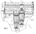
figure 1 est une coupe partielle d'un dispositif conforme à l'invention, où seule la partie comprenant le moyen de stockage, la zone de dépôt et l'organe de mise en couches ont été représentés, l'organe de mise en couches étant vu en coupe, en place dans une enceinte fermée, en position de dépose de la poudre au dessus de la zone de dépôt, le système de guidage extérieur à l'enceinte n'étant pas représenté, - la
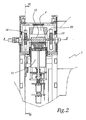
figure 2 est une coupe du dispositif représenté à la figure précédente, l'organe de mise en couches étant vu de face selon la flèche F à lafigure 1 , - la
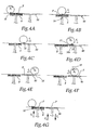
figure 3 est une représentation en perspective d'une partie de l'organe de mise en couches seul, - la
figure 3A est une coupe selon le plan III A à lafigure 3 , - les
figures 4A à 4G sont des schémas illustrant les différentes étapes de la prise de la poudre dans le moyen de stockage, de la dépose, de l'étalement, et du compactage de cette dernière sur la zone de dépôt, - la
figure 5 est une vue schématique partielle d'un organe de mise en couches conforme à un autre mode de réalisation et, - la
figure 6 est une coupe selon la ligne VI-VI à lafigure 2 , l'organe de mise en couches et les éléments de guidage et d'entraînement n'étant pas représentés.
- the
figure 1 is a partial section of a device according to the invention, where only the part comprising the storage means, the deposition zone and the layering member have been represented, the layering member being seen in FIG. cutting, in place in a closed chamber, in the powder depositing position above the deposition zone, the external guidance system to the enclosure not being shown, - the
figure 2 is a section of the device shown in the previous figure, the layering member being viewed from the front according to the arrow F at thefigure 1 , - the
figure 3 is a perspective representation of a portion of the layering member alone, - the
figure 3A is a cut according to the plan III A to thefigure 3 , - the
Figures 4A to 4G are diagrams illustrating the various steps of taking the powder in the storage means, the deposition, the spreading, and the compaction of the latter on the deposition zone, - the
figure 5 is a partial schematic view of a layering member according to another embodiment and, - the
figure 6 is a section along the line VI-VI to thefigure 2 , the layering member and the guiding and driving elements not being shown.
Le dispositif 1 représenté à la
Le fond 2 présente une face interne plane 5 pourvue, sur une partie, de deux orifices circulaires 6, respectivement 7, correspondant aux débouchés de deux puits ménagés dans l'appareil 1. Dans chaque orifice, un piston 8, respectivement 9, se déplace selon une direction globalement perpendiculaire au plan B, dans lequel se déplace l'axe longitudinal AA' de l'organe de mise en couches lors de son déplacement, et assure, temporairement, l'obturation de l'orifice 6, respectivement 7. Ainsi la face 5 forme un plan de travail continu. Ces pistons 8, 9 assurent l'étanchéité des puits et évitent que de la poudre, ou des gaz présent dans l'enceinte, passent dans ces derniers. Le déplacement de ces pistons 8, respectivement 9, s'effectue entre l'orifice 6, respectivement 7, et l'intérieur d'un puits cylindrique à base circulaire 10, respectivement 11, prolongeant les orifices 6, respectivement 7. Les pistons 8, 9 se déplacent indépendamment l'un de l'autre et ils sont actionnés chacun par un système motorisé, notamment par un moteur pas à pas, par un système vis écrou à billes de précision ou tout autre dispositif de mise en mouvement. Ces pistons sont guidés, lors de leur mouvement, par un moyen de guidage comme, par exemple, des éléments de guidage à billes précontraints. Le dispositif de guidage n'est pas soumis aux contraintes thermiques rencontrées dans l'appareil 1. Le déplacement des pistons 8 et 9 entre le fond des puits 10, respectivement 11, et les orifices 6, respectivement 7, s'effectue de manière précise. La précision obtenue, pour chaque piston, est d'environ plus ou moins un micron sur l'épaisseur d'une couche de poudre déposée.The
La face supérieure du piston 8 situé dans le puits 10 forme le fond d'un réservoir dans lequel est stocké une poudre P céramique ou métallique, ou un mélange de poudres céramiques ou métalliques. Il s'agit de produits habituellement disponibles dans le commerce.The upper face of the
L'orifice 7, dans lequel débouche le piston 9 qui se déplace à l'intérieur du puits 11, est situé globalement à l'aplomb du hublot 4 lorsque le couvercle 3 est fermé. Ce piston 9 supporte un plateau 90 qui forme la zone de dépôt sur laquelle la poudre P ou le mélange de poudres est déposé en couches minces préalablement à l'action du laser sur la matière.The
Le plateau 90 est positionné de façon amovible dans le puits 11, ce qui permet de transporter la pièce une fois réalisée sans avoir à manipuler directement cette dernière. Le plateau 90 est positionné avec précision sur le piston 9 afin de réaliser une mise en couche précise de la première couche de poudre, ou de mélange de poudres. Cette première couche assure le maintien et le positionnement de la pièce à réaliser et conditionne la qualité des couches suivantes.The
La course des pistons 8, respectivement 9, est adaptée pour que le piston 8, respectivement le plateau 90, affleurent à la face 5 aux points morts hauts de leurs trajectoires respectives.The stroke of the
A l'extérieur du fond 2, un système d'entraînement et de guidage, non représenté, assure le déplacement en rotation et en translation d'un organe 12 d'alimentation et de compactage de la poudre P ou du mélange de poudres entre les pistons 8 et 9. Le système de guidage est adapté pour assurer un guidage du fond 2 depuis l'extérieur tout en maintenant une isolation thermique de l'enceinte. Ce guidage à partir de l'extérieur permet de s'affranchir des contraintes thermiques et mécaniques rencontrées à l'intérieur de l'enceinte.Outside the
L'organe 12 est une pièce réalisée préférentiellement en céramiques. Avec un tel matériau, et avec une géométrie et des dimensions adaptées, l'organe 12 possède une stabilité dimensionnelle et géométrique importante qui lui évite de subir des déformations lorsque l'enceinte est chauffée à haute température, par exemple aux environ de 1200° C. De même, l'organe 12 offre une résistance à l'abrasion importante.The
L'organe 12 se présente sous la forme d'un cylindre à base circulaire pourvu à chacune de ses extrémités, en position centrale, de deux axes 13,14 orientés selon l'axe longitudinal AA' du cylindre. Ces axes 13, 14 débouchent sur l'extérieur du fond 2 en passant à travers les parois latérales de ce dernier et sont associés, à l'extérieur, à un dispositif d'entraînement et de guidage motorisé.The
L'état de surface de la surface externe 12a du cylindre est d'une qualité proche du « poli miroir » ou, pour le moins, plus lisse que l'état de surface de la zone de dépôt 9. Avantageusement, la surface 12a a une rugosité Ra inférieure ou égale à 0,06 microns.The surface state of the
L'étanchéité thermique, entre l'intérieur de l'enceinte et les moyens de guidage et d'entraînement extérieurs, est réalisés par la combinaison de volets 20, respectivement 21, de forme géométrique simple, notamment en forme de triangle, respectivement de parallélogramme. Ces volets 20, 21 sont disposés alternativement de manière à réaliser, de chaque côté de l'enceinte, une chicane. Ces volets sont en simple contact mécanique, ce qui assure entre eux un fonctionnement sans frottement et sans usure. Les volets 20, en triangle rectangle disposés de manière à former globalement un rectangle, sont mobiles alternativement selon une direction globalement parallèle au déplacement des pistons 8, 9. Les volets 21, en forme de parallélogramme, sont mobiles selon une direction globalement perpendiculaire au déplacement des pistons 8, 9. De cette manière, la chicane réalisée par les volets 20, 21 préserve l'étanchéité de l'enceinte.The thermal sealing, between the inside of the enclosure and the external guide and drive means, is achieved by the combination of
Avec une telle configuration, on réduit également l'encombrement du dispositif. Ainsi, on met en mouvement de manière précise le cylindre 12 qui se déplace, selon le plan B, au-dessus de la face 5 avec une course adaptée pour lui permettre de passer successivement au dessus des deux puits 10,11. Les paramètres d'asservissement du cylindre 12, par exemple sa position et sa vitesse de rotation, sont définis en fonction de la poudre, ou du mélange de poudres, de l'épaisseur de la couche à réaliser et d'autres paramètres de mise en oeuvre, comme, par exemple, la température.With such a configuration, the size of the device is also reduced. Thus, it moves in a precise manner the
Le cylindre 12 comprend, sur sa surface cylindrique externe, une rainure longitudinale 15. Cette rainure 15 est orientée selon une direction globalement parallèle à l'axe longitudinal AA' du cylindre 12. La rainure 15 présente une section globalement en forme de V, dont une paroi 15a est inclinée par rapport à un plan P15 de la rainure 15.The
Les parois 15a, 15b convergent en direction du fond 15c de la rainure 15. Une des parois 15b de cette rainure se termine par une arête 16 issue de l'intersection du plan P15 avec la surface cylindrique externe 12a du cylindre 12. De cette manière l'arête 16 forme une raclette permettant de ramasser la poudre P, ou le mélange de poudres, sur le piston 8 et de diriger la poudre, ou le mélange de poudres, vers le fond 15c de la rainure 15.The
La circonférence du cylindre 12 est adaptée pour que, lorsque celui-ci effectue une rotation complète autour de son axe AA', il se déplace d'une distance suffisante pour couvrir la totalité de la surface d'un des orifices 6 ou 7.The circumference of the
L'inclinaison de la paroi interne 15b de la rainure 15 est adaptée de manière à assurer un prélèvement efficace de la poudre, ou du mélange de poudres, lors du mouvement du cylindre 12 au-dessus du piston 8, tout en assurant ensuite un dépôt complet et rapide de la poudre P sur le plateau 90.The inclination of the
Dans un premier temps, représenté à la
Par rotation R1 du cylindre 12 autour de ses axes 13 et 14, on déplace angulairement ce dernier, ce qui amène en premier l'arête 16 de la rainure 15 au contact de la poudre P au voisinage de la périphérie du piston 8. Comme illustré à la
Comme représenté à la
On opère ensuite, comme illustré à la
De manière concomitante au dépôt de la poudre, le piston 9 s'est déplacé en direction de l'orifice 7, de manière à ce que l'intervalle entre le plateau 90 ou la couche précédemment déposée, et le cylindre 12 soit globalement égal à l'épaisseur de la couche de poudre étalée, avant compactage. Si nécessaire, on peut effectuer plusieurs opérations de ramassage et d'étalement de la poudre, ou du mélange de poudres. Pour cela, on fixe des épaisseurs intermédiaires des couches. En fonction de la nature de la poudre, ou du mélange de poudres, on paramètre la progression de l'épaisseur de la couche déposée. Cette progression est, par exemple, non linéaire décroissante du type y = (ax + b)/ (cx + d).Concomitantly with the deposition of the powder, the
Au terme de ce déplacement représenté à la
Cette rotation R2 est en sens inverse de la rotation R1 et elle ramène selon la flèche F2, le cylindre 12 à sa position initiale comme illustré à la
Lors du compactage, on déplace, si nécessaire, le piston 9 et le plateau 90 selon la direction F4 ou F'4 de manière concomitante au déplacement R2 , F2 du cylindre 12.During compaction, if necessary, the
Le déplacement F3 du piston 8 en direction de l'orifice 6 permet de remettre de la poudre P dans une position où elle peut être prélevée par la rainure 15.The displacement F 3 of the
Le déplacement selon F4 du piston 9 permet de mettre la surface supérieure de la couche précédemment déposée globalement coplanaire à la face 5.The displacement along F 4 of the
La couche de poudre, ou du mélange de poudres, ainsi étalée peut subir l'action d'un faisceau laser, par exemple dans un procédé de frittage ou de fusion, l'ensemble des opérations se faisant dans l'enceinte maintenue en température et de façon étanche aux gaz.The layer of powder, or of the mixture of powders, thus spread can be subjected to the action of a laser beam, for example in a sintering or melting process, all the operations being carried out in the enclosure maintained in temperature and in a gastight manner.
En variante la mise en couches de la poudre, ou du mélange de poudres, est réalisée à température ambiante, par exemple, avec l'enceinte ouverte.As a variant, the layering of the powder, or of the mixture of powders, is carried out at room temperature, for example with the open enclosure.
Il suffit alors de répéter les étapes précédentes pour étaler puis compacter successivement plusieurs couches de poudre P ou de mélange de poudres.It then suffices to repeat the previous steps to spread and then successively compact several layers of powder P or powder mixture.
Par un tel organe d'étalement et de compactage, on effectue la mise en place, avant l'action d'un laser sur la poudre, sur le plateau 90 de couches homogènes dont l'épaisseur peut descendre jusqu'à 5 microns selon la granulométrie de la poudre P utilisée. Il est possible, comme représenté à la
Un tel dispositif de mise en couches minces est donc utilisable en atmosphère confinée c'est-à-dire lorsque le couvercle 3 est fermé, éventuellement sous hautes températures et voire très hautes températures, ou à l'air libre notamment si la granulométrie et la nature de la poudre le permettent. Dans ce dernier cas le couvercle 3 reste ouvert. Les moyens de guidage, tant du cylindre 12 que des pistons 8 et 9, sont disposés à l'extérieur de l'enceinte de travail et des moyens d'étanchéité et d'isolation thermique les protègent de la poudre et de la haute température éventuelle.Such a thin-layering device is therefore usable in a confined atmosphere, that is to say when the
Dans une autre configuration et en fonction des diamètres des orifices 6 et 7 et/ou de leur entraxe, on utilise un cylindre 12 pourvu de plusieurs rainures 15 identiques ou non.In another configuration and as a function of the diameters of the
De même la forme de la rainure 15 peut être différente de celle représentée.Similarly, the shape of the
En variante, on peut ne ménager une rainure 15 que sur une partie de la longueur du cylindre 12.Alternatively, a
Claims (9)
- Device for putting into at least one thin layer a powder (P), or a mixture of powders, used during the action of a laser on material contained in a thermal enclosure, comprising a storage means (8), a means (12) for supplying with powder, or a mixture of powders, an area (9) for deposition of said powder or said mixture from said storage means and a means of compacting the powder or mixture of powders deposited on said deposition area, said device comprising a circular-based cylinder (12) provided, on the one hand, with at least one groove (15), made in an external surface of said cylinder (12), and, on the other hand, a surface (12a, 16a) adapted to compact the powder (P) or mixture of powders previously deposited on said deposition area (9), said cylinder (12), said storage means (8), said deposition area (9) and the powder (P) or mixture of powders being situated in said enclosure adapted to be temperature-maintained whilst allowing the guidance and driving of the cylinder (12) from the outside of said enclosure, said groove (15) being oriented in a direction overall parallel to the longitudinal axis (AA') of said cylinder (12) and being adapted to supply the deposition area (9) with powder or a mixture of powders from the storage means (8), by picking up the powder or mixture of powders (Figure 4B), moving the powder or mixture of powders by a translational movement of the cylinder (12), then providing a complete and rapid deposition (Figure 4D) of the powder or mixture of powders in the deposition area, the roughness of the external surface (12a) of said cylinder (12) being less than the roughness of the surface of said deposition area (9), the roughness of the external surface (12a) being adapted to the minimum granulometry of the powder (P) used.
- Device according to Claim 1, characterised in that said surface (12a, 16a) adapted to provide the compaction comprises at least one part (12a, 16a) of an external surface of said cylinder (12) in which at least one groove (15) is made.
- Device according to Claim 1, characterised in that said groove (15) extends, between the two ends of the cylinder (12), in a direction overall parallel to the longitudinal axis (AA') of said cylinder.
- Device according to one of the preceding claims, characterised in that said groove (15) has a cross-section configured overall as a flat-bottomed V.
- Device according to Claim 1, characterised in that the circumference of the cylinder (12) is substantially greater than the diameter of the deposition area (9).
- Device according to one of the preceding claims, characterised in that the temperature at which the enclosure and the elements (8, 9, 12, P) situated therein are maintained lies between the ambient temperature and approximately 1200°C.
- Device according to one of the preceding claims, characterised in that the positioning, guidance and driving of the cylinder (12) are performed by positioning and guidance members and an actuator which are situated outside the enclosure of the device.
- Device according to one of the preceding claims, characterised in that shutters (20, 21) disposed in the sides of the enclosure are movable in different directions with respect to a plane (B) in which the longitudinal axis (AA') of the cylinder (12) moves during movement of the latter.
- Device according to Claim 8, characterised in that the shutters (20, 21) are in the shape of a triangle (20) and a parallelogram (21), disposed in a staggered manner and in mutual contact, so as to provide the thermal insulation of the enclosure whilst allowing a connection between the positioning, guidance and driving members of said cylinder (12) and said cylinder.
Priority Applications (1)
| Application Number | Priority Date | Filing Date | Title |
|---|---|---|---|
| PL04767492T PL1641580T3 (en) | 2003-06-30 | 2004-06-28 | Device for the production of thin powder layers, in particular at high temperatures, during a method involving the use of a laser on a material |
Applications Claiming Priority (2)
| Application Number | Priority Date | Filing Date | Title |
|---|---|---|---|
| FR0307888A FR2856614B1 (en) | 2003-06-30 | 2003-06-30 | DEVICE FOR PRODUCING THIN LAYERS OF POWDER, PARTICULARLY AT HIGH TEMPERATURES, IN A PROCESS BASED ON THE ACTION OF A LASER ON THE MATERIAL |
| PCT/FR2004/001646 WO2005002764A1 (en) | 2003-06-30 | 2004-06-28 | Device for the production of thin powder layers, in particular at high temperatures, during a method involving the use of a laser on a material |
Publications (2)
| Publication Number | Publication Date |
|---|---|
| EP1641580A1 EP1641580A1 (en) | 2006-04-05 |
| EP1641580B1 true EP1641580B1 (en) | 2008-06-11 |
Family
ID=33515521
Family Applications (1)
| Application Number | Title | Priority Date | Filing Date |
|---|---|---|---|
| EP04767492A Active EP1641580B1 (en) | 2003-06-30 | 2004-06-28 | Device for the production of thin powder layers, in particular at high temperatures, during a method involving the use of a laser on a material |
Country Status (10)
| Country | Link |
|---|---|
| US (1) | US7789037B2 (en) |
| EP (1) | EP1641580B1 (en) |
| JP (1) | JP4778895B2 (en) |
| AT (1) | ATE397988T1 (en) |
| DE (1) | DE602004014376D1 (en) |
| DK (1) | DK1641580T3 (en) |
| ES (1) | ES2308232T3 (en) |
| FR (1) | FR2856614B1 (en) |
| PL (1) | PL1641580T3 (en) |
| WO (1) | WO2005002764A1 (en) |
Cited By (5)
| Publication number | Priority date | Publication date | Assignee | Title |
|---|---|---|---|---|
| WO2013092757A1 (en) | 2011-12-20 | 2013-06-27 | Compagnie Generale Des Etablissements Michelin | Machine and process for powder-based additive manufacturing |
| WO2013178825A2 (en) | 2012-06-01 | 2013-12-05 | Compagnie Generale Des Etablissements Michelin | Machine and method for powder-based additive manufacturing |
| WO2015082677A1 (en) | 2013-12-05 | 2015-06-11 | Compagnie Generale Des Etablissements Michelin | Machine and method for powder-based additive manufacturing |
| US9327451B2 (en) | 2011-04-19 | 2016-05-03 | Phenix Systems | Method for manufacturing an object by solidifying a powder using a laser |
| US11305349B2 (en) | 2016-03-14 | 2022-04-19 | Nanogrande | Method and apparatus for forming layers of particles for use in additive manufacturing |
Families Citing this family (53)
| Publication number | Priority date | Publication date | Assignee | Title |
|---|---|---|---|---|
| KR101307509B1 (en) * | 2005-05-11 | 2013-09-12 | 아르켐 에이비 | Powder application system |
| DE102006023484A1 (en) * | 2006-05-18 | 2007-11-22 | Eos Gmbh Electro Optical Systems | Apparatus and method for layering a three-dimensional object from a powdery building material |
| JP4882868B2 (en) * | 2007-05-24 | 2012-02-22 | パナソニック電工株式会社 | Manufacturing method of three-dimensional shaped object |
| FR2948044B1 (en) | 2009-07-15 | 2014-02-14 | Phenix Systems | THIN-LAYERING DEVICE AND METHOD OF USING SUCH A DEVICE |
| FR2949988B1 (en) | 2009-09-17 | 2011-10-07 | Phenix Systems | PROCESS FOR PRODUCING AN OBJECT BY LASER TREATMENT FROM AT LEAST TWO DIFFERENT PULVERULENT MATERIALS AND CORRESPONDING INSTALLATION |
| DE102010006939A1 (en) | 2010-02-04 | 2011-08-04 | Voxeljet Technology GmbH, 86167 | Device for producing three-dimensional models |
| GB201014950D0 (en) | 2010-09-08 | 2010-10-20 | Johnson Matthey Plc | Catalyst manufacturing method |
| DE102011007957A1 (en) | 2011-01-05 | 2012-07-05 | Voxeljet Technology Gmbh | Device and method for constructing a layer body with at least one body limiting the construction field and adjustable in terms of its position |
| FR2975319B1 (en) | 2011-05-17 | 2014-04-11 | Michelin Soc Tech | METHOD FOR MANUFACTURING LASER SINTER MOLDING ELEMENT |
| RU2487779C1 (en) * | 2012-05-11 | 2013-07-20 | Открытое акционерное общество "Национальный институт авиационных технологий" (ОАО НИАТ) | Plant for making parts by layer-by-layer synthesis |
| FR2996800B1 (en) | 2012-10-17 | 2014-11-14 | Michelin & Cie | MOLDING ELEMENT FOR A TIRE MOLD COMPRISING A POROUS ZONE |
| FR3002168B1 (en) | 2013-02-15 | 2016-12-23 | Michelin & Cie | PIECE OBTAINED BY SELECTIVE FUSION OF A POWDER COMPRISING A MAIN ELEMENT AND RIGID SECONDARY ELEMENTS |
| FR3002167B1 (en) | 2013-02-15 | 2016-12-23 | Michelin & Cie | PIECE OBTAINED BY SELECTIVE FUSION OF A POWDER COMPRISING A MAIN ELEMENT AND RIGID SECONDARY ELEMENTS |
| US11033961B2 (en) | 2014-01-09 | 2021-06-15 | Raytheon Technologies Corporation | Material and processes for additively manufacturing one or more parts |
| WO2015108849A1 (en) | 2014-01-14 | 2015-07-23 | United Technologies Corporation | Systems and processes for distributing material during additive manufacturing |
| US11235392B2 (en) | 2014-01-24 | 2022-02-01 | Raytheon Technologies Corporation | Monitoring material soldification byproducts during additive manufacturing |
| US10913129B2 (en) | 2014-01-24 | 2021-02-09 | Raytheon Technologies Corporation | Additive manufacturing an object from material with a selective diffusion barrier |
| WO2015112723A1 (en) | 2014-01-24 | 2015-07-30 | United Technologies Corporation | Conditioning one or more additive manufactured objects |
| US10576543B2 (en) | 2014-01-24 | 2020-03-03 | United Technologies Corporation | Alloying metal materials together during additive manufacturing or one or more parts |
| US9950392B2 (en) | 2014-03-04 | 2018-04-24 | Rohr, Inc. | Forming one or more apertures in a fiber-reinforced composite object with a laser |
| FR3018223B1 (en) | 2014-03-10 | 2017-11-03 | Michelin & Cie | PNEUMATIC COMPRISING A HIGH CONTRAST TEXTURE IN A GROOVE |
| FR3018224B1 (en) | 2014-03-10 | 2017-11-17 | Michelin & Cie | PNEUMATIC COMPRISING A HIGH-CONTRAST TEXTURE ON THE BEARING SURFACE |
| JP6390162B2 (en) * | 2014-05-16 | 2018-09-19 | 株式会社リコー | 3D modeling equipment |
| US9254535B2 (en) | 2014-06-20 | 2016-02-09 | Velo3D, Inc. | Apparatuses, systems and methods for three-dimensional printing |
| FR3030322B1 (en) | 2014-12-18 | 2019-03-15 | Compagnie Generale Des Etablissements Michelin | LASER SINKING PROCESS FOR THE PRODUCTION OF A BEARING BAND MOLDING MEMBER |
| GB201506325D0 (en) | 2015-04-14 | 2015-05-27 | Johnson Matthey Plc | Shaped catalyst particle |
| US10315408B2 (en) * | 2015-04-28 | 2019-06-11 | General Electric Company | Additive manufacturing apparatus and method |
| JP2017087469A (en) * | 2015-11-04 | 2017-05-25 | 株式会社リコー | Apparatus for three-dimensional fabrication |
| JP2018535121A (en) | 2015-11-06 | 2018-11-29 | ヴェロ・スリー・ディー・インコーポレイテッド | Proficient 3D printing |
| EP3386662A4 (en) | 2015-12-10 | 2019-11-13 | Velo3d Inc. | Skillful three-dimensional printing |
| US20170239891A1 (en) | 2016-02-18 | 2017-08-24 | Velo3D, Inc. | Accurate three-dimensional printing |
| EP3263300A1 (en) * | 2016-06-27 | 2018-01-03 | Siemens Aktiengesellschaft | Coating mechanism and apparatus for additive manufacturing |
| US11691343B2 (en) | 2016-06-29 | 2023-07-04 | Velo3D, Inc. | Three-dimensional printing and three-dimensional printers |
| US10286452B2 (en) | 2016-06-29 | 2019-05-14 | Velo3D, Inc. | Three-dimensional printing and three-dimensional printers |
| CN106001568B (en) * | 2016-07-07 | 2018-03-13 | 四川三阳激光增材制造技术有限公司 | A kind of functionally gradient material (FGM) metal die 3D printing integral preparation method |
| WO2018080507A1 (en) | 2016-10-27 | 2018-05-03 | Hewlett-Packard Development Company, L.P. | Recoater for 3d printers |
| US20180126462A1 (en) | 2016-11-07 | 2018-05-10 | Velo3D, Inc. | Gas flow in three-dimensional printing |
| US20180186082A1 (en) | 2017-01-05 | 2018-07-05 | Velo3D, Inc. | Optics in three-dimensional printing |
| US10569364B2 (en) | 2017-01-06 | 2020-02-25 | General Electric Company | Systems and methods for additive manufacturing recoating |
| US10315252B2 (en) | 2017-03-02 | 2019-06-11 | Velo3D, Inc. | Three-dimensional printing of three-dimensional objects |
| US20180281283A1 (en) | 2017-03-28 | 2018-10-04 | Velo3D, Inc. | Material manipulation in three-dimensional printing |
| WO2018182599A1 (en) * | 2017-03-29 | 2018-10-04 | Hewlett Packard Development Company, L.P. | Build material preparation in additive manufacturing |
| JP6904146B2 (en) * | 2017-08-01 | 2021-07-14 | トヨタ自動車株式会社 | 3D modeling equipment |
| AT520468B1 (en) | 2017-10-09 | 2021-02-15 | Weirather Maschb Und Zerspanungstechnik Gmbh | Device for the generative production of a component from a powdery starting material |
| US11225016B2 (en) * | 2017-10-20 | 2022-01-18 | Hewlett-Packard Development Company, L.P. | Additive manufacturing layers |
| US10272525B1 (en) | 2017-12-27 | 2019-04-30 | Velo3D, Inc. | Three-dimensional printing systems and methods of their use |
| US10144176B1 (en) | 2018-01-15 | 2018-12-04 | Velo3D, Inc. | Three-dimensional printing systems and methods of their use |
| EP3902645A1 (en) * | 2018-11-16 | 2021-11-03 | GMP Ingenierie | Removable adaptive additive manufacturing platform for equipment for metal additive manufacture by laser fusion |
| JP6958661B2 (en) * | 2020-02-10 | 2021-11-02 | 株式会社リコー | Three-dimensional modeling equipment |
| RU208175U1 (en) * | 2021-08-10 | 2021-12-07 | Федеральное государственное бюджетное образовательное учреждение высшего образования "Московский государственный технологический университет "СТАНКИН" (ФГБОУ ВО "МГТУ" СТАНКИН") | A device for obtaining products from polymers by layer-by-layer synthesis |
| US20230061660A1 (en) | 2021-08-26 | 2023-03-02 | The Goodyear Tire & Rubber Company | Mold segment and segmented tire mold with fluid-permeable infill |
| WO2023211317A1 (en) * | 2022-04-29 | 2023-11-02 | Общество с ограниченной ответственностью "АВП Инновации" | Method for additively manufacturing irregularly shaped articles |
| WO2023248524A1 (en) * | 2022-06-21 | 2023-12-28 | ローランドディー.ジー.株式会社 | Three-dimensional fabrication device |
Family Cites Families (12)
| Publication number | Priority date | Publication date | Assignee | Title |
|---|---|---|---|---|
| US1429089A (en) * | 1919-11-28 | 1922-09-12 | Francis R Schanck | Rotary scraper |
| US3854975A (en) * | 1971-06-30 | 1974-12-17 | Addressograph Multigraph | Pressure fixing of toners |
| US5876550A (en) * | 1988-10-05 | 1999-03-02 | Helisys, Inc. | Laminated object manufacturing apparatus and method |
| JPH0698690B2 (en) * | 1988-10-13 | 1994-12-07 | 松下電工株式会社 | Three-dimensional shape forming method |
| US5252264A (en) * | 1991-11-08 | 1993-10-12 | Dtm Corporation | Apparatus and method for producing parts with multi-directional powder delivery |
| DE19600075A1 (en) * | 1996-01-03 | 1997-07-10 | Hans Georg Platsch | Device for powdering printed matter |
| FR2774931B1 (en) * | 1998-02-19 | 2000-04-28 | Arnaud Hory | METHOD OF RAPID PROTOTYPING BY LASER POWDER SINTERING AND ASSOCIATED DEVICE |
| US6391251B1 (en) * | 1999-07-07 | 2002-05-21 | Optomec Design Company | Forming structures from CAD solid models |
| FR2802128B1 (en) * | 1999-12-10 | 2002-02-08 | Ecole Nale Sup Artes Metiers | DEVICE FOR DEPOSITING THIN LAYERS OF POWDER OR POWDER MATERIAL AND METHOD THEREOF |
| JP2001334581A (en) * | 2000-05-24 | 2001-12-04 | Minolta Co Ltd | Three-dimensional molding apparatus |
| US6533991B1 (en) * | 2000-06-20 | 2003-03-18 | Ipsen International, Inc. | Cooling gas injection nozzle for a vacuum heat treating furnace |
| JP3752427B2 (en) * | 2001-02-22 | 2006-03-08 | 株式会社日立製作所 | Solid object modeling method |
-
2003
- 2003-06-30 FR FR0307888A patent/FR2856614B1/en not_active Expired - Lifetime
-
2004
- 2004-06-28 JP JP2006518262A patent/JP4778895B2/en active Active
- 2004-06-28 DK DK04767492T patent/DK1641580T3/en active
- 2004-06-28 DE DE602004014376T patent/DE602004014376D1/en active Active
- 2004-06-28 WO PCT/FR2004/001646 patent/WO2005002764A1/en active IP Right Grant
- 2004-06-28 US US10/561,833 patent/US7789037B2/en active Active
- 2004-06-28 EP EP04767492A patent/EP1641580B1/en active Active
- 2004-06-28 PL PL04767492T patent/PL1641580T3/en unknown
- 2004-06-28 AT AT04767492T patent/ATE397988T1/en not_active IP Right Cessation
- 2004-06-28 ES ES04767492T patent/ES2308232T3/en active Active
Cited By (5)
| Publication number | Priority date | Publication date | Assignee | Title |
|---|---|---|---|---|
| US9327451B2 (en) | 2011-04-19 | 2016-05-03 | Phenix Systems | Method for manufacturing an object by solidifying a powder using a laser |
| WO2013092757A1 (en) | 2011-12-20 | 2013-06-27 | Compagnie Generale Des Etablissements Michelin | Machine and process for powder-based additive manufacturing |
| WO2013178825A2 (en) | 2012-06-01 | 2013-12-05 | Compagnie Generale Des Etablissements Michelin | Machine and method for powder-based additive manufacturing |
| WO2015082677A1 (en) | 2013-12-05 | 2015-06-11 | Compagnie Generale Des Etablissements Michelin | Machine and method for powder-based additive manufacturing |
| US11305349B2 (en) | 2016-03-14 | 2022-04-19 | Nanogrande | Method and apparatus for forming layers of particles for use in additive manufacturing |
Also Published As
| Publication number | Publication date |
|---|---|
| DE602004014376D1 (en) | 2008-07-24 |
| US7789037B2 (en) | 2010-09-07 |
| DK1641580T3 (en) | 2008-10-06 |
| ES2308232T3 (en) | 2008-12-01 |
| WO2005002764A1 (en) | 2005-01-13 |
| ATE397988T1 (en) | 2008-07-15 |
| FR2856614B1 (en) | 2006-08-11 |
| PL1641580T3 (en) | 2008-11-28 |
| US20070245950A1 (en) | 2007-10-25 |
| FR2856614A1 (en) | 2004-12-31 |
| EP1641580A1 (en) | 2006-04-05 |
| JP2007516342A (en) | 2007-06-21 |
| JP4778895B2 (en) | 2011-09-21 |
Similar Documents
| Publication | Publication Date | Title |
|---|---|---|
| EP1641580B1 (en) | Device for the production of thin powder layers, in particular at high temperatures, during a method involving the use of a laser on a material | |
| EP2454040B1 (en) | Device for forming thin films and method for using such a device | |
| EP1235650B1 (en) | Device for applying thin layers of a powder or pulverulent material and corresponding method | |
| EP2879819B1 (en) | Machine and method for powder-based additive manufacturing | |
| EP2367614B1 (en) | Device for depositing a powder mixture for forming an object with composition gradients, and related method | |
| FR2540471A1 (en) | REFRACTORY BOX LOADER, CONVEYOR APPARATUS AND METHOD | |
| EP2773475B1 (en) | Apparatus for manufacturing parts by selective melting of powder | |
| EP1058675A1 (en) | Fast prototyping method by laser sintering of powder and related device | |
| WO2020089538A1 (en) | Additive manufacturing machine with movable, controlled powder dispensing | |
| EP0743160A1 (en) | Apparatus for the manufacture of fiber reinforced thermoplastic articles for automobiles | |
| EP1568424B1 (en) | Press for holding and pressing a workpiece | |
| EP3758871B1 (en) | Additive manufacturing machine comprising a device for the distribution of powder onto a mobile surface using vibration | |
| EP0620061B1 (en) | Device for rapid changing and holding a side wall in a twin roll continuous casting machinen for casting a metallic product | |
| CH627668A5 (en) | METHOD AND DEVICE FOR OVERMOLDING SURFACES OF THERMOPLASTIC MATERIAL, ESPECIALLY SKIS SOLE. | |
| EP3787877B1 (en) | Additive manufacturing machine comprising a device for the distribution of powder onto a mobile surface using a screw distributor | |
| EP0679113B1 (en) | Method and plant for producing amorphous metal strips by ultrafast quenching | |
| EP3802130A1 (en) | Method for preparing the upper surface of an additive manufacturing platen by depositing a bed of powder | |
| EP0855206B1 (en) | Deaeration apparatus and process for viscous or pasty substances | |
| FR2672831A1 (en) | High-rate friction welding machine | |
| FR2757092A1 (en) | DEVICE FOR APPLYING A LIQUID TO AN OBJECT, APPLICATION TO BREWING A SOLID MATERIAL IN A SAMPLE HOLDER | |
| EP3953149A1 (en) | Additive manufacturing machine comprising a movable surface for receiving powder optimised to retain the grains of powder | |
| FR3098751A1 (en) | Additive manufacturing process using a stencil | |
| FR2702738A1 (en) | Method and machine for the manufacture of plastic pouches intended to serve as flexible fluid-tight packages for pasty products | |
| WO2016120562A1 (en) | Method and device for manufacturing a component from powder |
Legal Events
| Date | Code | Title | Description |
|---|---|---|---|
| PUAI | Public reference made under article 153(3) epc to a published international application that has entered the european phase |
Free format text: ORIGINAL CODE: 0009012 |
|
| 17P | Request for examination filed |
Effective date: 20051222 |
|
| AK | Designated contracting states |
Kind code of ref document: A1 Designated state(s): AT BE BG CH CY CZ DE DK EE ES FI FR GB GR HU IE IT LI LU MC NL PL PT RO SE SI SK TR |
|
| 17Q | First examination report despatched |
Effective date: 20060705 |
|
| DAX | Request for extension of the european patent (deleted) | ||
| 17Q | First examination report despatched |
Effective date: 20060705 |
|
| GRAP | Despatch of communication of intention to grant a patent |
Free format text: ORIGINAL CODE: EPIDOSNIGR1 |
|
| GRAS | Grant fee paid |
Free format text: ORIGINAL CODE: EPIDOSNIGR3 |
|
| GRAA | (expected) grant |
Free format text: ORIGINAL CODE: 0009210 |
|
| AK | Designated contracting states |
Kind code of ref document: B1 Designated state(s): AT BE BG CH CY CZ DE DK EE ES FI FR GB GR HU IE IT LI LU MC NL PL PT RO SE SI SK TR |
|
| REG | Reference to a national code |
Ref country code: GB Ref legal event code: FG4D Free format text: NOT ENGLISH |
|
| REG | Reference to a national code |
Ref country code: CH Ref legal event code: EP |
|
| REF | Corresponds to: |
Ref document number: 602004014376 Country of ref document: DE Date of ref document: 20080724 Kind code of ref document: P |
|
| REG | Reference to a national code |
Ref country code: RO Ref legal event code: EPE |
|
| REG | Reference to a national code |
Ref country code: IE Ref legal event code: FG4D Free format text: LANGUAGE OF EP DOCUMENT: FRENCH |
|
| PG25 | Lapsed in a contracting state [announced via postgrant information from national office to epo] |
Ref country code: SI Free format text: LAPSE BECAUSE OF FAILURE TO SUBMIT A TRANSLATION OF THE DESCRIPTION OR TO PAY THE FEE WITHIN THE PRESCRIBED TIME-LIMIT Effective date: 20080611 |
|
| PG25 | Lapsed in a contracting state [announced via postgrant information from national office to epo] |
Ref country code: AT Free format text: LAPSE BECAUSE OF FAILURE TO SUBMIT A TRANSLATION OF THE DESCRIPTION OR TO PAY THE FEE WITHIN THE PRESCRIBED TIME-LIMIT Effective date: 20080611 |
|
| REG | Reference to a national code |
Ref country code: PL Ref legal event code: T3 |
|
| REG | Reference to a national code |
Ref country code: ES Ref legal event code: FG2A Ref document number: 2308232 Country of ref document: ES Kind code of ref document: T3 |
|
| PG25 | Lapsed in a contracting state [announced via postgrant information from national office to epo] |
Ref country code: SE Free format text: LAPSE BECAUSE OF FAILURE TO SUBMIT A TRANSLATION OF THE DESCRIPTION OR TO PAY THE FEE WITHIN THE PRESCRIBED TIME-LIMIT Effective date: 20080911 Ref country code: PT Free format text: LAPSE BECAUSE OF FAILURE TO SUBMIT A TRANSLATION OF THE DESCRIPTION OR TO PAY THE FEE WITHIN THE PRESCRIBED TIME-LIMIT Effective date: 20081111 |
|
| REG | Reference to a national code |
Ref country code: IE Ref legal event code: FD4D |
|
| PG25 | Lapsed in a contracting state [announced via postgrant information from national office to epo] |
Ref country code: SK Free format text: LAPSE BECAUSE OF FAILURE TO SUBMIT A TRANSLATION OF THE DESCRIPTION OR TO PAY THE FEE WITHIN THE PRESCRIBED TIME-LIMIT Effective date: 20080611 |
|
| PLBE | No opposition filed within time limit |
Free format text: ORIGINAL CODE: 0009261 |
|
| STAA | Information on the status of an ep patent application or granted ep patent |
Free format text: STATUS: NO OPPOSITION FILED WITHIN TIME LIMIT |
|
| PG25 | Lapsed in a contracting state [announced via postgrant information from national office to epo] |
Ref country code: EE Free format text: LAPSE BECAUSE OF FAILURE TO SUBMIT A TRANSLATION OF THE DESCRIPTION OR TO PAY THE FEE WITHIN THE PRESCRIBED TIME-LIMIT Effective date: 20080611 Ref country code: IE Free format text: LAPSE BECAUSE OF FAILURE TO SUBMIT A TRANSLATION OF THE DESCRIPTION OR TO PAY THE FEE WITHIN THE PRESCRIBED TIME-LIMIT Effective date: 20080611 Ref country code: BG Free format text: LAPSE BECAUSE OF FAILURE TO SUBMIT A TRANSLATION OF THE DESCRIPTION OR TO PAY THE FEE WITHIN THE PRESCRIBED TIME-LIMIT Effective date: 20080911 |
|
| 26N | No opposition filed |
Effective date: 20090312 |
|
| PG25 | Lapsed in a contracting state [announced via postgrant information from national office to epo] |
Ref country code: HU Free format text: LAPSE BECAUSE OF FAILURE TO SUBMIT A TRANSLATION OF THE DESCRIPTION OR TO PAY THE FEE WITHIN THE PRESCRIBED TIME-LIMIT Effective date: 20081212 Ref country code: CY Free format text: LAPSE BECAUSE OF FAILURE TO SUBMIT A TRANSLATION OF THE DESCRIPTION OR TO PAY THE FEE WITHIN THE PRESCRIBED TIME-LIMIT Effective date: 20080611 |
|
| PG25 | Lapsed in a contracting state [announced via postgrant information from national office to epo] |
Ref country code: TR Free format text: LAPSE BECAUSE OF FAILURE TO SUBMIT A TRANSLATION OF THE DESCRIPTION OR TO PAY THE FEE WITHIN THE PRESCRIBED TIME-LIMIT Effective date: 20080611 |
|
| PG25 | Lapsed in a contracting state [announced via postgrant information from national office to epo] |
Ref country code: GR Free format text: LAPSE BECAUSE OF FAILURE TO SUBMIT A TRANSLATION OF THE DESCRIPTION OR TO PAY THE FEE WITHIN THE PRESCRIBED TIME-LIMIT Effective date: 20080912 |
|
| REG | Reference to a national code |
Ref country code: FR Ref legal event code: PLFP Year of fee payment: 13 |
|
| REG | Reference to a national code |
Ref country code: FR Ref legal event code: PLFP Year of fee payment: 14 |
|
| REG | Reference to a national code |
Ref country code: FR Ref legal event code: PLFP Year of fee payment: 15 |
|
| PGFP | Annual fee paid to national office [announced via postgrant information from national office to epo] |
Ref country code: RO Payment date: 20220609 Year of fee payment: 19 Ref country code: NL Payment date: 20220626 Year of fee payment: 19 Ref country code: MC Payment date: 20220603 Year of fee payment: 19 Ref country code: LU Payment date: 20220627 Year of fee payment: 19 Ref country code: IT Payment date: 20220621 Year of fee payment: 19 Ref country code: GB Payment date: 20220628 Year of fee payment: 19 Ref country code: DK Payment date: 20220629 Year of fee payment: 19 Ref country code: CZ Payment date: 20220610 Year of fee payment: 19 |
|
| PGFP | Annual fee paid to national office [announced via postgrant information from national office to epo] |
Ref country code: PL Payment date: 20220602 Year of fee payment: 19 Ref country code: FI Payment date: 20220629 Year of fee payment: 19 Ref country code: BE Payment date: 20220627 Year of fee payment: 19 |
|
| PGFP | Annual fee paid to national office [announced via postgrant information from national office to epo] |
Ref country code: FR Payment date: 20220627 Year of fee payment: 19 |
|
| PGFP | Annual fee paid to national office [announced via postgrant information from national office to epo] |
Ref country code: ES Payment date: 20220701 Year of fee payment: 19 Ref country code: DE Payment date: 20220629 Year of fee payment: 19 |
|
| PGFP | Annual fee paid to national office [announced via postgrant information from national office to epo] |
Ref country code: CH Payment date: 20220706 Year of fee payment: 19 |
|
| P01 | Opt-out of the competence of the unified patent court (upc) registered |
Effective date: 20230419 |
|
| REG | Reference to a national code |
Ref country code: DE Ref legal event code: R119 Ref document number: 602004014376 Country of ref document: DE |
|
| PG25 | Lapsed in a contracting state [announced via postgrant information from national office to epo] |
Ref country code: MC Free format text: LAPSE BECAUSE OF NON-PAYMENT OF DUE FEES Effective date: 20230630 |
|
| REG | Reference to a national code |
Ref country code: DK Ref legal event code: EBP Effective date: 20230630 |
|
| PG25 | Lapsed in a contracting state [announced via postgrant information from national office to epo] |
Ref country code: RO Free format text: LAPSE BECAUSE OF NON-PAYMENT OF DUE FEES Effective date: 20230628 Ref country code: MC Free format text: LAPSE BECAUSE OF NON-PAYMENT OF DUE FEES Effective date: 20230630 Ref country code: FI Free format text: LAPSE BECAUSE OF NON-PAYMENT OF DUE FEES Effective date: 20230628 Ref country code: CZ Free format text: LAPSE BECAUSE OF NON-PAYMENT OF DUE FEES Effective date: 20230628 |
|
| REG | Reference to a national code |
Ref country code: CH Ref legal event code: PL |
|
| REG | Reference to a national code |
Ref country code: NL Ref legal event code: MM Effective date: 20230701 |
|
| REG | Reference to a national code |
Ref country code: BE Ref legal event code: MM Effective date: 20230630 |
|
| GBPC | Gb: european patent ceased through non-payment of renewal fee |
Effective date: 20230628 |
|
| PG25 | Lapsed in a contracting state [announced via postgrant information from national office to epo] |
Ref country code: LU Free format text: LAPSE BECAUSE OF NON-PAYMENT OF DUE FEES Effective date: 20230628 |