EP1641534B1 - Multi-leaf collimator - Google Patents
Multi-leaf collimator Download PDFInfo
- Publication number
- EP1641534B1 EP1641534B1 EP04740746A EP04740746A EP1641534B1 EP 1641534 B1 EP1641534 B1 EP 1641534B1 EP 04740746 A EP04740746 A EP 04740746A EP 04740746 A EP04740746 A EP 04740746A EP 1641534 B1 EP1641534 B1 EP 1641534B1
- Authority
- EP
- European Patent Office
- Prior art keywords
- collimator
- leaves
- leaf
- leaf collimator
- radiation source
- Prior art date
- Legal status (The legal status is an assumption and is not a legal conclusion. Google has not performed a legal analysis and makes no representation as to the accuracy of the status listed.)
- Expired - Lifetime
Links
Images



Classifications
-
- G—PHYSICS
- G21—NUCLEAR PHYSICS; NUCLEAR ENGINEERING
- G21K—HANDLING OF PARTICLES OR IONISING RADIATION NOT OTHERWISE PROVIDED FOR; IRRADIATION DEVICES; GAMMA RAY OR X-RAY MICROSCOPES
- G21K1/00—Arrangements for handling particles or ionising radiation, e.g. focusing or moderating
- G21K1/02—Arrangements for handling particles or ionising radiation, e.g. focusing or moderating using diaphragms, collimators
- G21K1/04—Arrangements for handling particles or ionising radiation, e.g. focusing or moderating using diaphragms, collimators using variable diaphragms, shutters, choppers
- G21K1/046—Arrangements for handling particles or ionising radiation, e.g. focusing or moderating using diaphragms, collimators using variable diaphragms, shutters, choppers varying the contour of the field, e.g. multileaf collimators
-
- A—HUMAN NECESSITIES
- A61—MEDICAL OR VETERINARY SCIENCE; HYGIENE
- A61N—ELECTROTHERAPY; MAGNETOTHERAPY; RADIATION THERAPY; ULTRASOUND THERAPY
- A61N5/00—Radiation therapy
- A61N5/10—X-ray therapy; Gamma-ray therapy; Particle-irradiation therapy
- A61N5/1042—X-ray therapy; Gamma-ray therapy; Particle-irradiation therapy with spatial modulation of the radiation beam within the treatment head
-
- G—PHYSICS
- G21—NUCLEAR PHYSICS; NUCLEAR ENGINEERING
- G21K—HANDLING OF PARTICLES OR IONISING RADIATION NOT OTHERWISE PROVIDED FOR; IRRADIATION DEVICES; GAMMA RAY OR X-RAY MICROSCOPES
- G21K1/00—Arrangements for handling particles or ionising radiation, e.g. focusing or moderating
- G21K1/02—Arrangements for handling particles or ionising radiation, e.g. focusing or moderating using diaphragms, collimators
- G21K1/025—Arrangements for handling particles or ionising radiation, e.g. focusing or moderating using diaphragms, collimators using multiple collimators, e.g. Bucky screens; other devices for eliminating undesired or dispersed radiation
-
- G—PHYSICS
- G21—NUCLEAR PHYSICS; NUCLEAR ENGINEERING
- G21K—HANDLING OF PARTICLES OR IONISING RADIATION NOT OTHERWISE PROVIDED FOR; IRRADIATION DEVICES; GAMMA RAY OR X-RAY MICROSCOPES
- G21K1/00—Arrangements for handling particles or ionising radiation, e.g. focusing or moderating
- G21K1/02—Arrangements for handling particles or ionising radiation, e.g. focusing or moderating using diaphragms, collimators
- G21K1/04—Arrangements for handling particles or ionising radiation, e.g. focusing or moderating using diaphragms, collimators using variable diaphragms, shutters, choppers
Definitions
- the present invention relates to a multi-leaf collimator.
- Multi-leaf collimators are used (principally) in the field of radiotherapy.
- a beam of radiation is directed toward a patient and must be collimated to fit the shape of the area to be treated. It is important to ensure that the dose in the areas outside that shape is as low as possible, but also that the whole area is treated. If areas are left untreated then the likelihood of recurrence is increased, whereas if non-treatment regions are irradiated then damage will be caused to healthy tissue resulting in greater side effects and longer recovery times after treatment.
- multi-leaf collimator are employed. These comprise an array of finger-shaped leaves of a radiation-absorbing material, each disposed in a parallel relationship and each able to move longitudinally relative to the others. By moving each leaf to a selected position, a collimator is provided which can exhibit a non-linear edge. In general, one such array (or “bank”) will be provided on each side of the beam.
- Multi-leaf collimators generally suffer from two difficulties. One is the leakage of radiation between the leaves of the bank, and the other is that the leaves often have square ends and thus exhibit a pixellated pattern when aligned to an edge that is non-perpendicular to the leaf direction.
- IMRT Intensity Modulated Radiation Therapy
- JP03009767 suggests the use of two banks of leaves, offset so that the leaves of one cover the gaps between leaves of the other. This results in an improved resolution and reduced leakage, but still gives a pixellated effect.
- the present invention seeks to provide a multi-leaf collimator which further alleviates the problems of inter-leaf leakage and pixellation and provides improved resolution and large field size.
- the present invention therefore provides a collimator for a radiation beam comprising a first multi-leaf collimator set, a second multi-leaf collimator set with its leaves at an acute angle to the leaves of the first multi-leaf collimator, and a third multi-leaf collimator set with its leaves at an acute angle to the leaves of the second multi-leaf collimator.
- Each multi-leaf collimator set will usually Include a pair of leaf banks mutually opposed to each other.
- the acute angle between the first and the second multi-leaf collimator set is preferably the same as the acute angle between the second and the third set.
- a suitable angle is approximately 60°, however other suitable angles may also be used.
- the penumbra is the region close to the radiation field edge.
- the penumbral width is typically defined by the distance between the points where 20% and 80% of the dose at central axis is delivered.
- a small penumbra means a good beam definition which allows to give maximum dose to a target volume with a rapid dose fall off next to it towards the surrounding normal healthy tissue.
- the first multi-leaf collimator is closest to the radiation source, the third multi-leaf collimator is furthest from the radiation source, and the second multi-leaf collimator is between the first and third multi-leaf collimators.
- Figure 1 shows the relevant part of a beam collimator 1 of conventional design.
- the collimator 1 comprises a set of a pair of multi-leaf banks 2, 2a disposed in a plane orthogonal to the direction of the X-ray or other beam 3 exiting from the aperture 4.
- Figure 2 shows the collimator 10 according to the present invention, in a corresponding vertical plane (i.e. in the direction of the beam 3) to Figure 1 of the conventional type of collimator.
- the collimator comprises three multi-leaf sets, 11a, 11b and 11c, each set comprising a multi-leaf bank disposed on either side of the X-ray beam 3, and each disposed in a row in the vertical section.
- the three banks are arranged in different orientations, such as with their leaf direction at 60° to each other.
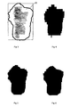
- Figure 3 shows a typical clinical sample 20 with an irregular, rectilinear shape, which is to be treated using treatment plans such as IMRT.
- the area inside the solid black line forming the perimeter of the shape is the tissue which must be treated with X-rays or other radiation.
- the tissue surrounding the treatment area i.e. the healthy tissue
- the area to be treated must receive the radiation treatment whilst the healthy tissue must be shielded from the radiation using suitable radiation-blocking material.
- Figure 4 shows the achieved irradiation pattern using a two-bank multi-leaf collimator such as the conventional type shown in JP03009767 .
- the width of the leaves in this particular example are of 10mm.
- the width of the leaves is measured in the plane orthogonal to the direction of the beam. As can be seen, large areas of healthy tissue will be irradiated due to the approximate boundary that is achieved using the conventional two-bank multi-leaf collimator.
- the width of the leaves is decreased, i.e. to achieve a better resolution, in this example to 4mm to produce a mini-collimator, the resulting irradiation pattern is closer to the pattern of the tissue to be treated, as shown in Figure 5.
- the narrower the leaves of the bank the better the resolution, however, the leaves of the bank can only be narrowed to a finite width as engineering challenges become insurmountable.
- the narrower the leaves of the bank the smaller becomes the practically achievable field size, thus making it difficult to treat large areas.
- the field size of the conventional two bank multi-leaf collimator is of the order of 40 x 40 cm 2 .
- the field size of the mini-collimator is of the order of 16 x 20 cm 2 .
- the field size of the collimator according to the present invention is at least 40cm diameter, and may be greater.
- Figure 6 shows the achieved irradiation pattern using a collimator according to the present invention, with 10mm wide leaves.
- the target irradiation pattern is improved substantially over that achieved by using either the 10mm width leaves of the conventional two-bank multi-leaf collimator or the narrower leaves of the mini-collimator used to achieve the pattern in Figure 5.
- Figure 7 shows the overdose, i.e. irradiation of healthy tissue, applied for a standard target and range of orientations.
- the overdose is minimum in only two orientations, i.e. when the area to be treated has a vertical or horizontal edge and thus the leaves of the conventional collimator may be placed in a close abutting relationship with the edge.
- the mini-collimator where again the overdose forms minima at two orientations.
- the results of the collimator according to the present invention show a marked and substantial improvement in the reduction of the overdose, as can be seen from the graph, most of the overdose line lies well below the line achieved using the mini-collimator.
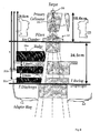
- FIG 8 shows the embodiment according to a second aspect of the invention.
- the multi-leaf collimator set is shown partially fitted into an accelerator.
- the accelerator comprises a target to generate the radiation, a primary collimator 31 which partially collimates the beam 3, and filters 32 to filter the beam.
- the beam then passes through the multi-leaf collimator according to a second aspect of the invention.
- the depth of the leaves is measured in a direction parallel to the direction of the X-ray beam 3.
- the depth of the bank of leaves 31a is the greatest, the depth of the second bank 31b is less than the depth of the first bank of leaves and the depth of bank of leaves 31c is less than the depth of the second bank of leaves.
- the leaves are also curved in the direction parallel to the direction of the beam, with the radius of curvature of the first bank of leaves 31a being greater than the radius of curvature of the second bank of leaves 31b.
- the radius of curvature of the third bank of leaves 31c is smaller than the radius of curvature of the second bank of leaves.
- Figure 9 shows the resulting penumbra for this second aspect of the invention, which is improved almost two-fold compared with the conventional two-bank collimator.
- the percentage of the area outside of the collimator pattern that receives between 20-100% of the radiation for a conventional two-bank collimator is typically of the order of 13%.
- the mini-collimator this is reduced to around 8%, but the multi-bank collimator according to the present invention, achieves a fluency of around 7%.
- the multi-bank multi-leaf collimator of the present invention includes the advantages of the large two-bank conventional collimator in terms of the field size and yet has the fluency, resolution and performance of the mini-collimator.
- the use of a collimator according to the present invention allows the design of MLC heads that are significantly simpler.
- the leaves need not employ tongue and groove mechanisms at their joint, as other banks of leaves above and/or below can cover these joins.
- the collimator head does not need to be rotateable as the collimator is less directional.
Landscapes
- Physics & Mathematics (AREA)
- Engineering & Computer Science (AREA)
- Health & Medical Sciences (AREA)
- Spectroscopy & Molecular Physics (AREA)
- General Engineering & Computer Science (AREA)
- High Energy & Nuclear Physics (AREA)
- Biomedical Technology (AREA)
- Nuclear Medicine, Radiotherapy & Molecular Imaging (AREA)
- Pathology (AREA)
- Radiology & Medical Imaging (AREA)
- Life Sciences & Earth Sciences (AREA)
- Animal Behavior & Ethology (AREA)
- General Health & Medical Sciences (AREA)
- Public Health (AREA)
- Veterinary Medicine (AREA)
- Radiation-Therapy Devices (AREA)
- Apparatus For Radiation Diagnosis (AREA)
- Nuclear Medicine (AREA)
- Optical Couplings Of Light Guides (AREA)
Abstract
Description
- The present invention relates to a multi-leaf collimator.
- Multi-leaf collimators (MLC) are used (principally) in the field of radiotherapy. A beam of radiation is directed toward a patient and must be collimated to fit the shape of the area to be treated. It is important to ensure that the dose in the areas outside that shape is as low as possible, but also that the whole area is treated. If areas are left untreated then the likelihood of recurrence is increased, whereas if non-treatment regions are irradiated then damage will be caused to healthy tissue resulting in greater side effects and longer recovery times after treatment.
- As the treatment area is rarely rectilinear, multi-leaf collimator are employed. These comprise an array of finger-shaped leaves of a radiation-absorbing material, each disposed in a parallel relationship and each able to move longitudinally relative to the others. By moving each leaf to a selected position, a collimator is provided which can exhibit a non-linear edge. In general, one such array (or "bank") will be provided on each side of the beam.
- Multi-leaf collimators generally suffer from two difficulties. One is the leakage of radiation between the leaves of the bank, and the other is that the leaves often have square ends and thus exhibit a pixellated pattern when aligned to an edge that is non-perpendicular to the leaf direction.
- Various designs are employed to resolve the leakage rate, including stepped edges to the leaves, which therefore interlock (to an extent) and limit the clear view between leaves. However, Inter-leaf leakage is a limiting factor in some treatment plans such as Intensity Modulated Radiation Therapy (IMRT) where the treatment time is relatively long.
- The pixellation issue is a factor related to the resolution of the leaf bank, and therefore efforts to alleviate this problem tend to involve the use of narrower leaves. This does, however, make the collimator more complex and present significant engineering challenges.
JP03009767 - A similar multiple layer multileaf collimator is also described in
WO-A-99/17305 - The present invention seeks to provide a multi-leaf collimator which further alleviates the problems of inter-leaf leakage and pixellation and provides improved resolution and large field size.
- The present invention therefore provides a collimator for a radiation beam comprising a first multi-leaf collimator set, a second multi-leaf collimator set with its leaves at an acute angle to the leaves of the first multi-leaf collimator, and a third multi-leaf collimator set with its leaves at an acute angle to the leaves of the second multi-leaf collimator.
- Each multi-leaf collimator set will usually Include a pair of leaf banks mutually opposed to each other.
- The acute angle between the first and the second multi-leaf collimator set is preferably the same as the acute angle between the second and the third set. A suitable angle is approximately 60°, however other suitable angles may also be used.
- The penumbra is the region close to the radiation field edge. The penumbral width is typically defined by the distance between the points where 20% and 80% of the dose at central axis is delivered. A small penumbra means a good beam definition which allows to give maximum dose to a target volume with a rapid dose fall off next to it towards the surrounding normal healthy tissue.
- A number of design features in such a collimator are preferred in order to improve the penumbra characteristics:
- The leaves of the multi-leaf collimator closest to the radiation source can be deeper in the direction of the radiation than the leaves of a multi-leaf collimator more distant from the radiation source.
- The leaves of the multi-leaf collimator furthest from the radiation source can be shallower in the direction of the radiation than the leaves of a multi-leaf collimator closer to the radiation source.
- The tips of the leaves of the multi-leaf collimators can be rounded.
- The radius of curvature of the tips of the leaves of the multi-leaf collimator closest to the radiation source can be greater than the radius of curvature of the tips of the leaves of a multi-leaf collimator more distant from the radiation source.
- The radius of curvature of the tips of the leaves of the multi-leaf collimator furthest from the radiation source can be less than the radius of curvature of the tips of the leaves of a multi-leaf collimator closer to the radiation source.
- In general, it is also preferred that the first multi-leaf collimator is closest to the radiation source, the third multi-leaf collimator is furthest from the radiation source, and the second multi-leaf collimator is between the first and third multi-leaf collimators.
- An embodiment of the present invention will now be described by way of example, with reference to the accompanying figures in which;
- Figure 1 shows a known single bank multi-leaf collimator in vertical section;
- Figure 2 shows a multi-leaf collimator according to the present invention in a corresponding vertical section;
- Figure 3 shows a typical clinical example;
- Figure 4 shows the achieved irradiation pattern using a two-bank multi-leaf collimator with 10mm leaves;
- Figure 5 shows the achieved irradiation pattern using a two-bank multi-leaf collimator with 4mm leaves;
- Figure 6 shows the achieved irradiation pattern using a three bank multi-leaf collimator according to the present invention with 10mm leaves;
- Figure 7 shows the overdose applied for a standard target at a range of orientations;
- Figure 8 shows a vertical section through an accelerator partially fitted with a multi-leaf collimator according to the second aspect of the invention; and
- Figure 9 shows the penumbra profile achieved by the multi-leaf collimator of figure 8.
- Figure 1 shows the relevant part of a
beam collimator 1 of conventional design. Thecollimator 1 comprises a set of a pair ofmulti-leaf banks other beam 3 exiting from theaperture 4. - Figure 2 shows the
collimator 10 according to the present invention, in a corresponding vertical plane (i.e. in the direction of the beam 3) to Figure 1 of the conventional type of collimator. The collimator comprises three multi-leaf sets, 11a, 11b and 11c, each set comprising a multi-leaf bank disposed on either side of theX-ray beam 3, and each disposed in a row in the vertical section. What is not visible in Figure 2 is that the three banks are arranged in different orientations, such as with their leaf direction at 60° to each other. - Figure 3 shows a typical
clinical sample 20 with an irregular, rectilinear shape, which is to be treated using treatment plans such as IMRT. The area inside the solid black line forming the perimeter of the shape is the tissue which must be treated with X-rays or other radiation. In order that the tissue surrounding the treatment area, i.e. the healthy tissue, is not affected, the area to be treated must receive the radiation treatment whilst the healthy tissue must be shielded from the radiation using suitable radiation-blocking material. - Figure 4 shows the achieved irradiation pattern using a two-bank multi-leaf collimator such as the conventional type shown in
JP03009767 - If the width of the leaves is decreased, i.e. to achieve a better resolution, in this example to 4mm to produce a mini-collimator, the resulting irradiation pattern is closer to the pattern of the tissue to be treated, as shown in Figure 5. Of course, the narrower the leaves of the bank, the better the resolution, however, the leaves of the bank can only be narrowed to a finite width as engineering challenges become insurmountable. Furthermore, the narrower the leaves of the bank, the smaller becomes the practically achievable field size, thus making it difficult to treat large areas.
- The field size of the conventional two bank multi-leaf collimator is of the order of 40 x 40 cm2. The field size of the mini-collimator is of the order of 16 x 20 cm2. The field size of the collimator according to the present invention, however, is at least 40cm diameter, and may be greater.
- Figure 6 shows the achieved irradiation pattern using a collimator according to the present invention, with 10mm wide leaves. As can be seen the target irradiation pattern is improved substantially over that achieved by using either the 10mm width leaves of the conventional two-bank multi-leaf collimator or the narrower leaves of the mini-collimator used to achieve the pattern in Figure 5.
- Figure 7 shows the overdose, i.e. irradiation of healthy tissue, applied for a standard target and range of orientations. As can be seen, using the conventional two-bank collimator, the overdose is minimum in only two orientations, i.e. when the area to be treated has a vertical or horizontal edge and thus the leaves of the conventional collimator may be placed in a close abutting relationship with the edge. The same is true of the mini-collimator, where again the overdose forms minima at two orientations. The results of the collimator according to the present invention, show a marked and substantial improvement in the reduction of the overdose, as can be seen from the graph, most of the overdose line lies well below the line achieved using the mini-collimator.
- Figure 8 shows the embodiment according to a second aspect of the invention. The multi-leaf collimator set is shown partially fitted into an accelerator. The accelerator comprises a target to generate the radiation, a
primary collimator 31 which partially collimates thebeam 3, and filters 32 to filter the beam. The beam then passes through the multi-leaf collimator according to a second aspect of the invention. The depth of the leaves is measured in a direction parallel to the direction of theX-ray beam 3. The depth of the bank ofleaves 31a is the greatest, the depth of thesecond bank 31b is less than the depth of the first bank of leaves and the depth of bank ofleaves 31c is less than the depth of the second bank of leaves. - The leaves are also curved in the direction parallel to the direction of the beam, with the radius of curvature of the first bank of
leaves 31a being greater than the radius of curvature of the second bank ofleaves 31b. The radius of curvature of the third bank ofleaves 31c, is smaller than the radius of curvature of the second bank of leaves. - Figure 9 shows the resulting penumbra for this second aspect of the invention, which is improved almost two-fold compared with the conventional two-bank collimator. The percentage of the area outside of the collimator pattern that receives between 20-100% of the radiation for a conventional two-bank collimator is typically of the order of 13%. For the mini-collimator this is reduced to around 8%, but the multi-bank collimator according to the present invention, achieves a fluency of around 7%.
- Therefore, it can be seen that the multi-bank multi-leaf collimator of the present invention includes the advantages of the large two-bank conventional collimator in terms of the field size and yet has the fluency, resolution and performance of the mini-collimator.
- In addition, the use of a collimator according to the present invention allows the design of MLC heads that are significantly simpler. The leaves need not employ tongue and groove mechanisms at their joint, as other banks of leaves above and/or below can cover these joins. Furthermore, the collimator head does not need to be rotateable as the collimator is less directional.
- It will of course be understood that many variations may be made to the above-described embodiment without departing from the scope of the present invention.
Claims (10)
- A collimator for a radiation beam comprising:a first multi-leaf collimator set (11a) ;a second multi-leaf collimator (11b) set with its leaves at an acute angle to the leaves of the first multi-leaf collimator (11a); anda third multi-leaf collimator set (11c) with its-leaves at an acute angle to the leaves of the second multi-leaf collimator (11b).
- A collimator according to claim 1 in which each multi-leaf collimator set (11a, 11b, 11c) includes a pair of leaf banks mutually opposed to each other.
- A collimator according to claim 1 or claim 2 in which the acute angle between the first and the second multi-leaf collimator set (11a, 11b) is the same as the acute angle between the second and the third set (11b, 11c).
- A collimator according to any one of the preceding claims in which the or one of the acute angles is 60°.
- A collimator according to any one of the preceding claims in which the leaves (31a) of the multi-leaf collimator closest to the radiation source (30) are deeper in the direction of the radiation than the leaves (31b, 31c) of a multi-leaf collimator more distant from the radiation source (30).
- A collimator according to any one of the preceding claims in which the leaves (31c) of the multi-leaf collimator furthest from the radiation source (30) are shallower in the direction of the radiation than the leaves (31a, 31b) of a multi-leaf collimator closer to the radiation source.
- A collimator according to any one of the preceding claims in which the tips of the leaves (31a, 31b, 31c) of the multi-leaf collimators are rounded.
- A collimator according to claim 7 in which the radius of curvature of the tips of the leaves (31a) of the multi-leaf collimator closest to the radiation source (30) is greater than the radius of curvature of the tips of the leaves (31b, 31c) of a multi-leaf collimator more distant from the radiation source (30).
- A collimator according to claim 7 or claim 8 in which the radius of curvature of the tips of the leaves (31c) of the multi-leaf collimator furthest from the radiation source (30) is less than the radius of curvature of the tips of the leaves (31a, 31b) of a multi-leaf collimator closer to the radiation source (30).
- A collimator according to any one of the preceding claims, in which the first multi-leaf collimator (11a) is closest to the radiation source (30), the third multi-leaf collimator (11b) is furthest from the radiation source (30), and the second multi-leaf collimator (11b) is between the first and third multi-leaf collimators (11a, 11c).
Applications Claiming Priority (2)
| Application Number | Priority Date | Filing Date | Title |
|---|---|---|---|
| GB0315909A GB2403884B (en) | 2003-07-08 | 2003-07-08 | Multi-leaf collimator |
| PCT/EP2004/007433 WO2005004987A1 (en) | 2003-07-08 | 2004-07-07 | Multi-leaf collimator |
Publications (2)
| Publication Number | Publication Date |
|---|---|
| EP1641534A1 EP1641534A1 (en) | 2006-04-05 |
| EP1641534B1 true EP1641534B1 (en) | 2007-09-12 |
Family
ID=27741747
Family Applications (1)
| Application Number | Title | Priority Date | Filing Date |
|---|---|---|---|
| EP04740746A Expired - Lifetime EP1641534B1 (en) | 2003-07-08 | 2004-07-07 | Multi-leaf collimator |
Country Status (8)
| Country | Link |
|---|---|
| US (1) | US7095823B2 (en) |
| EP (1) | EP1641534B1 (en) |
| JP (1) | JP2009513172A (en) |
| CN (1) | CN100569316C (en) |
| AT (1) | ATE372812T1 (en) |
| DE (1) | DE602004008918T2 (en) |
| GB (1) | GB2403884B (en) |
| WO (1) | WO2005004987A1 (en) |
Families Citing this family (45)
| Publication number | Priority date | Publication date | Assignee | Title |
|---|---|---|---|---|
| US7397903B2 (en) * | 2003-11-20 | 2008-07-08 | Ge Medical Systems Global Technology Company, Llc | Collimator and radiation irradiator |
| AU2005216070B2 (en) * | 2004-02-20 | 2012-01-19 | University Of Florida Research Foundation, Inc. | System for delivering conformal radiation therapy while simultaneously imaging soft tissue |
| GB2418828B (en) * | 2004-09-30 | 2008-07-09 | Elekta Ab | Anti reflective stepped profile for surfaces of radiotherapeutic apparatus |
| US9451928B2 (en) | 2006-09-13 | 2016-09-27 | Elekta Ltd. | Incorporating internal anatomy in clinical radiotherapy setups |
| US7826593B2 (en) | 2006-12-19 | 2010-11-02 | C-Rad Innovation Ab | Collimator |
| CA2688019C (en) | 2007-05-24 | 2014-08-05 | Elekta Ab (Publ) | Collimation apparatus for radiotherapy |
| CA2693351C (en) | 2007-07-20 | 2017-06-13 | Resonant Medical Inc. | Methods and systems for compensating for changes in anatomy of radiotherapy patients |
| US10531858B2 (en) | 2007-07-20 | 2020-01-14 | Elekta, LTD | Methods and systems for guiding the acquisition of ultrasound images |
| US8135198B2 (en) | 2007-08-08 | 2012-03-13 | Resonant Medical, Inc. | Systems and methods for constructing images |
| GB2457072A (en) | 2008-02-01 | 2009-08-05 | Elekta Ab | Fluorescence vision system |
| JP5509196B2 (en) * | 2008-04-21 | 2014-06-04 | エレクタ・アーベー・(ペーウーベーエル) | Improvement on multileaf collimator or improvement on multileaf collimator |
| US8938051B2 (en) | 2008-04-21 | 2015-01-20 | Elekta Ab (Publ) | Multi-leaf collimators |
| US8189738B2 (en) | 2008-06-02 | 2012-05-29 | Elekta Ltd. | Methods and systems for guiding clinical radiotherapy setups |
| US10542962B2 (en) | 2009-07-10 | 2020-01-28 | Elekta, LTD | Adaptive radiotherapy treatment using ultrasound |
| JP2011019633A (en) | 2009-07-14 | 2011-02-03 | Toshiba Corp | X-ray diagnostic apparatus and control program for reducing exposure dose |
| US20110172526A1 (en) | 2010-01-12 | 2011-07-14 | Martin Lachaine | Feature Tracking Using Ultrasound |
| US9248316B2 (en) | 2010-01-12 | 2016-02-02 | Elekta Ltd. | Feature tracking using ultrasound |
| US8537373B2 (en) * | 2010-03-02 | 2013-09-17 | Elekta Ab (Publ) | Position detection |
| US8637841B2 (en) | 2010-08-23 | 2014-01-28 | Varian Medical Systems, Inc. | Multi level multileaf collimators |
| US8519370B2 (en) | 2011-04-11 | 2013-08-27 | Elekta Ab (Publ) | Modifying radiation beam shapes |
| DE102011081038B4 (en) * | 2011-08-16 | 2015-06-18 | Siemens Aktiengesellschaft | multileaf collimator |
| US10561861B2 (en) | 2012-05-02 | 2020-02-18 | Viewray Technologies, Inc. | Videographic display of real-time medical treatment |
| JP6382208B2 (en) | 2012-10-26 | 2018-08-29 | ビューレイ・テクノロジーズ・インコーポレイテッドViewRay Technologies, Inc. | System and computer program product |
| US9446263B2 (en) | 2013-03-15 | 2016-09-20 | Viewray Technologies, Inc. | Systems and methods for linear accelerator radiotherapy with magnetic resonance imaging |
| US9962560B2 (en) * | 2013-12-20 | 2018-05-08 | Mevion Medical Systems, Inc. | Collimator and energy degrader |
| US10675487B2 (en) | 2013-12-20 | 2020-06-09 | Mevion Medical Systems, Inc. | Energy degrader enabling high-speed energy switching |
| US10071263B1 (en) | 2014-03-25 | 2018-09-11 | Varian Medical Systems, Inc. | Pivoting multileaf collimator and method for large field coverage |
| WO2017070433A1 (en) * | 2015-10-23 | 2017-04-27 | The Regents Of The University Of California | A platform for intensity modulated radiation therapy |
| US10786689B2 (en) | 2015-11-10 | 2020-09-29 | Mevion Medical Systems, Inc. | Adaptive aperture |
| CN108367160A (en) | 2015-11-24 | 2018-08-03 | 优瑞技术公司 | Collimation of radiation beams system and method |
| CN109310879A (en) | 2016-03-02 | 2019-02-05 | 优瑞技术公司 | Particle Therapy Using Magnetic Resonance Imaging |
| JP7098539B2 (en) | 2016-06-22 | 2022-07-11 | ビューレイ・テクノロジーズ・インコーポレイテッド | Magnetic resonance imaging |
| CN106139415A (en) * | 2016-07-06 | 2016-11-23 | 沈阳东软医疗系统有限公司 | The control method for movement of a kind of multi-diaphragm collimator movable support bracket and device |
| WO2018009779A1 (en) | 2016-07-08 | 2018-01-11 | Mevion Medical Systems, Inc. | Treatment planning |
| RU2019121943A (en) | 2016-12-13 | 2021-01-15 | Вьюрэй Текнолоджиз, Инк. | SYSTEMS AND METHODS OF RADIOTHERAPY |
| CN106693217A (en) * | 2017-02-16 | 2017-05-24 | 四川大学 | Radiotherapy system variable rectangular radiation field collimator |
| WO2019006253A1 (en) | 2017-06-30 | 2019-01-03 | Mevion Medical Systems, Inc. | Configurable collimator controlled using linear motors |
| JP7127126B2 (en) | 2017-12-06 | 2022-08-29 | ビューレイ・テクノロジーズ・インコーポレイテッド | Radiation therapy system, method and software |
| EP3546024B1 (en) | 2018-03-30 | 2020-10-21 | Varian Medical Systems Inc | Apparatus for using a multi-layer multi-leaf collimator as a virtual flattening filter |
| US11209509B2 (en) | 2018-05-16 | 2021-12-28 | Viewray Technologies, Inc. | Resistive electromagnet systems and methods |
| US10709905B2 (en) * | 2018-06-29 | 2020-07-14 | Victor Hernandez | Method of calculating a tongue-and-groove effect of a multi-leaf collimator |
| CN111643819A (en) * | 2019-03-04 | 2020-09-11 | 深圳市艾华联盟科技有限公司 | Multi-blade collimator with three-layer structure |
| US20210265071A1 (en) * | 2020-02-26 | 2021-08-26 | Varian Medical Systems International Ag | Beam-blocking leaf and multileaf collimator containing same |
| CN111714789B (en) * | 2020-06-19 | 2022-09-27 | 新里程医用加速器(无锡)有限公司 | Multi-blade grating and manufacturing method of grating blade thereof |
| EP4172603A4 (en) * | 2020-06-25 | 2024-08-07 | Smiths Detection Inc. | Systems and methods for real-time configurable backscatter scanners |
Family Cites Families (8)
| Publication number | Priority date | Publication date | Assignee | Title |
|---|---|---|---|---|
| GB2211710A (en) * | 1987-10-28 | 1989-07-05 | Philips Nv | Multileaf collimator |
| GB2211709B (en) * | 1987-10-28 | 1991-03-20 | Philips Electronic Associated | Multileaf collimator and related apparatus |
| EP0371303B1 (en) * | 1988-11-29 | 1994-04-27 | Varian International AG. | Radiation therapy apparatus |
| JPH0767491B2 (en) * | 1989-06-08 | 1995-07-26 | 三菱電機株式会社 | Multi-leaf collimator |
| US5166531A (en) * | 1991-08-05 | 1992-11-24 | Varian Associates, Inc. | Leaf-end configuration for multileaf collimator |
| US5748703A (en) * | 1994-03-22 | 1998-05-05 | Cosman; Eric R. | Dynamic collimator for a linear accelerator |
| CN1178711A (en) * | 1997-09-17 | 1998-04-15 | 戴建荣 | Use of independent collimator in adaptive radiotherapy |
| IL121866A (en) * | 1997-09-29 | 2000-11-21 | Ein Gal Moshe | Multiple layer multileaf collimator |
-
2003
- 2003-07-08 GB GB0315909A patent/GB2403884B/en not_active Expired - Fee Related
-
2004
- 2004-07-07 EP EP04740746A patent/EP1641534B1/en not_active Expired - Lifetime
- 2004-07-07 JP JP2006518132A patent/JP2009513172A/en active Pending
- 2004-07-07 AT AT04740746T patent/ATE372812T1/en not_active IP Right Cessation
- 2004-07-07 CN CNB2004800194497A patent/CN100569316C/en not_active Expired - Fee Related
- 2004-07-07 WO PCT/EP2004/007433 patent/WO2005004987A1/en not_active Ceased
- 2004-07-07 DE DE602004008918T patent/DE602004008918T2/en not_active Expired - Lifetime
- 2004-07-07 US US10/888,264 patent/US7095823B2/en not_active Expired - Lifetime
Also Published As
| Publication number | Publication date |
|---|---|
| JP2009513172A (en) | 2009-04-02 |
| GB0315909D0 (en) | 2003-08-13 |
| EP1641534A1 (en) | 2006-04-05 |
| GB2403884B (en) | 2006-03-01 |
| CN100569316C (en) | 2009-12-16 |
| ATE372812T1 (en) | 2007-09-15 |
| US7095823B2 (en) | 2006-08-22 |
| US20050008123A1 (en) | 2005-01-13 |
| DE602004008918D1 (en) | 2007-10-25 |
| WO2005004987A1 (en) | 2005-01-20 |
| CN1819856A (en) | 2006-08-16 |
| GB2403884A (en) | 2005-01-12 |
| DE602004008918T2 (en) | 2008-06-12 |
Similar Documents
| Publication | Publication Date | Title |
|---|---|---|
| US7095823B2 (en) | Multi-leaf collimator | |
| US5166531A (en) | Leaf-end configuration for multileaf collimator | |
| US10773102B2 (en) | Radiotherapy and imaging apparatus | |
| US10722732B2 (en) | Multi level multileaf collimator leaf tip shape effects and penumbra optimization | |
| US11975216B2 (en) | Radiation treatment head and radiation treatment device | |
| US6449336B2 (en) | Multi-source intensity-modulated radiation beam delivery system and method | |
| US7977657B2 (en) | Ion radiation therapy system with distal gradient tracking | |
| CN114452550B (en) | Beam flow distribution system for ion Flash treatment | |
| US20050058245A1 (en) | Intensity-modulated radiation therapy with a multilayer multileaf collimator | |
| JP5095816B2 (en) | Aiming device for radiation therapy | |
| US10583311B2 (en) | Collimation apparatus for radiotherapy | |
| US12285631B2 (en) | Adjustable multi-slit collimators | |
| GB2341301A (en) | Collimator for radiotherapy apparatus | |
| CN113692303B (en) | Multileaf collimator cones for stereotactic radiosurgery | |
| Lv et al. | Performance study of the dynamic multi-leaf collimator system (DMLC-120) | |
| US20130034211A1 (en) | Radiotherapy | |
| US12233284B2 (en) | SRS contoured multi-layer multileaf collimator | |
| Gao et al. | Proton beam spatially fractionated radiotherapy | |
| JP2006081800A (en) | Multistage multileaf collimator and radiotherapy device | |
| Galvin et al. | Dosimetric characterization of a multileaf collimator system | |
| Kligerman et al. | Initiation of multileaf collimator-based conformal radiation therapy |
Legal Events
| Date | Code | Title | Description |
|---|---|---|---|
| PUAI | Public reference made under article 153(3) epc to a published international application that has entered the european phase |
Free format text: ORIGINAL CODE: 0009012 |
|
| 17P | Request for examination filed |
Effective date: 20051207 |
|
| AK | Designated contracting states |
Kind code of ref document: A1 Designated state(s): AT BE BG CH CY CZ DE DK EE ES FI FR GB GR HU IE IT LI LU MC NL PL PT RO SE SI SK TR |
|
| 17Q | First examination report despatched |
Effective date: 20060831 |
|
| DAX | Request for extension of the european patent (deleted) | ||
| GRAP | Despatch of communication of intention to grant a patent |
Free format text: ORIGINAL CODE: EPIDOSNIGR1 |
|
| GRAS | Grant fee paid |
Free format text: ORIGINAL CODE: EPIDOSNIGR3 |
|
| GRAA | (expected) grant |
Free format text: ORIGINAL CODE: 0009210 |
|
| AK | Designated contracting states |
Kind code of ref document: B1 Designated state(s): AT BE BG CH CY CZ DE DK EE ES FI FR GB GR HU IE IT LI LU MC NL PL PT RO SE SI SK TR |
|
| REG | Reference to a national code |
Ref country code: GB Ref legal event code: FG4D |
|
| REG | Reference to a national code |
Ref country code: CH Ref legal event code: EP |
|
| REF | Corresponds to: |
Ref document number: 602004008918 Country of ref document: DE Date of ref document: 20071025 Kind code of ref document: P |
|
| REG | Reference to a national code |
Ref country code: IE Ref legal event code: FG4D |
|
| PG25 | Lapsed in a contracting state [announced via postgrant information from national office to epo] |
Ref country code: FI Free format text: LAPSE BECAUSE OF FAILURE TO SUBMIT A TRANSLATION OF THE DESCRIPTION OR TO PAY THE FEE WITHIN THE PRESCRIBED TIME-LIMIT Effective date: 20070912 |
|
| PG25 | Lapsed in a contracting state [announced via postgrant information from national office to epo] |
Ref country code: CH Free format text: LAPSE BECAUSE OF FAILURE TO SUBMIT A TRANSLATION OF THE DESCRIPTION OR TO PAY THE FEE WITHIN THE PRESCRIBED TIME-LIMIT Effective date: 20070912 Ref country code: AT Free format text: LAPSE BECAUSE OF FAILURE TO SUBMIT A TRANSLATION OF THE DESCRIPTION OR TO PAY THE FEE WITHIN THE PRESCRIBED TIME-LIMIT Effective date: 20070912 Ref country code: PL Free format text: LAPSE BECAUSE OF FAILURE TO SUBMIT A TRANSLATION OF THE DESCRIPTION OR TO PAY THE FEE WITHIN THE PRESCRIBED TIME-LIMIT Effective date: 20070912 Ref country code: LI Free format text: LAPSE BECAUSE OF FAILURE TO SUBMIT A TRANSLATION OF THE DESCRIPTION OR TO PAY THE FEE WITHIN THE PRESCRIBED TIME-LIMIT Effective date: 20070912 |
|
| NLV1 | Nl: lapsed or annulled due to failure to fulfill the requirements of art. 29p and 29m of the patents act | ||
| PG25 | Lapsed in a contracting state [announced via postgrant information from national office to epo] |
Ref country code: BE Free format text: LAPSE BECAUSE OF FAILURE TO SUBMIT A TRANSLATION OF THE DESCRIPTION OR TO PAY THE FEE WITHIN THE PRESCRIBED TIME-LIMIT Effective date: 20070912 |
|
| REG | Reference to a national code |
Ref country code: CH Ref legal event code: PL |
|
| PG25 | Lapsed in a contracting state [announced via postgrant information from national office to epo] |
Ref country code: NL Free format text: LAPSE BECAUSE OF FAILURE TO SUBMIT A TRANSLATION OF THE DESCRIPTION OR TO PAY THE FEE WITHIN THE PRESCRIBED TIME-LIMIT Effective date: 20070912 Ref country code: ES Free format text: LAPSE BECAUSE OF FAILURE TO SUBMIT A TRANSLATION OF THE DESCRIPTION OR TO PAY THE FEE WITHIN THE PRESCRIBED TIME-LIMIT Effective date: 20071223 Ref country code: GR Free format text: LAPSE BECAUSE OF FAILURE TO SUBMIT A TRANSLATION OF THE DESCRIPTION OR TO PAY THE FEE WITHIN THE PRESCRIBED TIME-LIMIT Effective date: 20071213 |
|
| PG25 | Lapsed in a contracting state [announced via postgrant information from national office to epo] |
Ref country code: PT Free format text: LAPSE BECAUSE OF FAILURE TO SUBMIT A TRANSLATION OF THE DESCRIPTION OR TO PAY THE FEE WITHIN THE PRESCRIBED TIME-LIMIT Effective date: 20080212 Ref country code: CZ Free format text: LAPSE BECAUSE OF FAILURE TO SUBMIT A TRANSLATION OF THE DESCRIPTION OR TO PAY THE FEE WITHIN THE PRESCRIBED TIME-LIMIT Effective date: 20070912 Ref country code: SK Free format text: LAPSE BECAUSE OF FAILURE TO SUBMIT A TRANSLATION OF THE DESCRIPTION OR TO PAY THE FEE WITHIN THE PRESCRIBED TIME-LIMIT Effective date: 20070912 |
|
| PG25 | Lapsed in a contracting state [announced via postgrant information from national office to epo] |
Ref country code: SE Free format text: LAPSE BECAUSE OF FAILURE TO SUBMIT A TRANSLATION OF THE DESCRIPTION OR TO PAY THE FEE WITHIN THE PRESCRIBED TIME-LIMIT Effective date: 20071212 Ref country code: RO Free format text: LAPSE BECAUSE OF FAILURE TO SUBMIT A TRANSLATION OF THE DESCRIPTION OR TO PAY THE FEE WITHIN THE PRESCRIBED TIME-LIMIT Effective date: 20070912 |
|
| PLBE | No opposition filed within time limit |
Free format text: ORIGINAL CODE: 0009261 |
|
| STAA | Information on the status of an ep patent application or granted ep patent |
Free format text: STATUS: NO OPPOSITION FILED WITHIN TIME LIMIT |
|
| PG25 | Lapsed in a contracting state [announced via postgrant information from national office to epo] |
Ref country code: DK Free format text: LAPSE BECAUSE OF FAILURE TO SUBMIT A TRANSLATION OF THE DESCRIPTION OR TO PAY THE FEE WITHIN THE PRESCRIBED TIME-LIMIT Effective date: 20070912 |
|
| 26N | No opposition filed |
Effective date: 20080613 |
|
| PG25 | Lapsed in a contracting state [announced via postgrant information from national office to epo] |
Ref country code: MC Free format text: LAPSE BECAUSE OF NON-PAYMENT OF DUE FEES Effective date: 20080731 |
|
| PG25 | Lapsed in a contracting state [announced via postgrant information from national office to epo] |
Ref country code: EE Free format text: LAPSE BECAUSE OF FAILURE TO SUBMIT A TRANSLATION OF THE DESCRIPTION OR TO PAY THE FEE WITHIN THE PRESCRIBED TIME-LIMIT Effective date: 20070912 |
|
| PG25 | Lapsed in a contracting state [announced via postgrant information from national office to epo] |
Ref country code: SI Free format text: LAPSE BECAUSE OF FAILURE TO SUBMIT A TRANSLATION OF THE DESCRIPTION OR TO PAY THE FEE WITHIN THE PRESCRIBED TIME-LIMIT Effective date: 20070912 |
|
| PG25 | Lapsed in a contracting state [announced via postgrant information from national office to epo] |
Ref country code: CY Free format text: LAPSE BECAUSE OF FAILURE TO SUBMIT A TRANSLATION OF THE DESCRIPTION OR TO PAY THE FEE WITHIN THE PRESCRIBED TIME-LIMIT Effective date: 20070912 Ref country code: IE Free format text: LAPSE BECAUSE OF NON-PAYMENT OF DUE FEES Effective date: 20080707 |
|
| PG25 | Lapsed in a contracting state [announced via postgrant information from national office to epo] |
Ref country code: BG Free format text: LAPSE BECAUSE OF FAILURE TO SUBMIT A TRANSLATION OF THE DESCRIPTION OR TO PAY THE FEE WITHIN THE PRESCRIBED TIME-LIMIT Effective date: 20071212 |
|
| PG25 | Lapsed in a contracting state [announced via postgrant information from national office to epo] |
Ref country code: LU Free format text: LAPSE BECAUSE OF NON-PAYMENT OF DUE FEES Effective date: 20080707 Ref country code: HU Free format text: LAPSE BECAUSE OF FAILURE TO SUBMIT A TRANSLATION OF THE DESCRIPTION OR TO PAY THE FEE WITHIN THE PRESCRIBED TIME-LIMIT Effective date: 20080313 |
|
| PG25 | Lapsed in a contracting state [announced via postgrant information from national office to epo] |
Ref country code: TR Free format text: LAPSE BECAUSE OF FAILURE TO SUBMIT A TRANSLATION OF THE DESCRIPTION OR TO PAY THE FEE WITHIN THE PRESCRIBED TIME-LIMIT Effective date: 20070912 |
|
| PGFP | Annual fee paid to national office [announced via postgrant information from national office to epo] |
Ref country code: GB Payment date: 20100517 Year of fee payment: 7 |
|
| PG25 | Lapsed in a contracting state [announced via postgrant information from national office to epo] |
Ref country code: IT Free format text: LAPSE BECAUSE OF NON-PAYMENT OF DUE FEES Effective date: 20080731 |
|
| PGFP | Annual fee paid to national office [announced via postgrant information from national office to epo] |
Ref country code: DE Payment date: 20100930 Year of fee payment: 7 |
|
| GBPC | Gb: european patent ceased through non-payment of renewal fee |
Effective date: 20110707 |
|
| PG25 | Lapsed in a contracting state [announced via postgrant information from national office to epo] |
Ref country code: DE Free format text: LAPSE BECAUSE OF NON-PAYMENT OF DUE FEES Effective date: 20120201 |
|
| REG | Reference to a national code |
Ref country code: DE Ref legal event code: R119 Ref document number: 602004008918 Country of ref document: DE Effective date: 20120201 |
|
| PG25 | Lapsed in a contracting state [announced via postgrant information from national office to epo] |
Ref country code: GB Free format text: LAPSE BECAUSE OF NON-PAYMENT OF DUE FEES Effective date: 20110707 |
|
| PG25 | Lapsed in a contracting state [announced via postgrant information from national office to epo] |
Ref country code: FR Free format text: LAPSE BECAUSE OF FAILURE TO SUBMIT A TRANSLATION OF THE DESCRIPTION OR TO PAY THE FEE WITHIN THE PRESCRIBED TIME-LIMIT Effective date: 20070912 |
|
| P01 | Opt-out of the competence of the unified patent court (upc) registered |
Effective date: 20230529 |