EP1641511B1 - Catheter with occlusion resistant tip - Google Patents
Catheter with occlusion resistant tip Download PDFInfo
- Publication number
- EP1641511B1 EP1641511B1 EP04776849A EP04776849A EP1641511B1 EP 1641511 B1 EP1641511 B1 EP 1641511B1 EP 04776849 A EP04776849 A EP 04776849A EP 04776849 A EP04776849 A EP 04776849A EP 1641511 B1 EP1641511 B1 EP 1641511B1
- Authority
- EP
- European Patent Office
- Prior art keywords
- lumen
- catheter
- wall extension
- cavity
- wall
- Prior art date
- Legal status (The legal status is an assumption and is not a legal conclusion. Google has not performed a legal analysis and makes no representation as to the accuracy of the status listed.)
- Expired - Lifetime
Links
- 239000012530 fluid Substances 0.000 claims description 76
- 230000017531 blood circulation Effects 0.000 description 47
- 208000007536 Thrombosis Diseases 0.000 description 17
- 239000008280 blood Substances 0.000 description 12
- 210000004369 blood Anatomy 0.000 description 12
- 230000002441 reversible effect Effects 0.000 description 9
- 238000000502 dialysis Methods 0.000 description 6
- 238000001631 haemodialysis Methods 0.000 description 6
- 238000000034 method Methods 0.000 description 6
- 239000002245 particle Substances 0.000 description 6
- 210000004204 blood vessel Anatomy 0.000 description 5
- 230000007704 transition Effects 0.000 description 4
- 238000011282 treatment Methods 0.000 description 4
- 230000001154 acute effect Effects 0.000 description 3
- -1 for example Substances 0.000 description 3
- 210000003734 kidney Anatomy 0.000 description 3
- 238000004519 manufacturing process Methods 0.000 description 3
- 239000000463 material Substances 0.000 description 3
- 230000004888 barrier function Effects 0.000 description 2
- 230000000322 hemodialysis Effects 0.000 description 2
- 238000012986 modification Methods 0.000 description 2
- 230000004048 modification Effects 0.000 description 2
- 229920000642 polymer Polymers 0.000 description 2
- 238000004804 winding Methods 0.000 description 2
- 239000004743 Polypropylene Substances 0.000 description 1
- FAPWRFPIFSIZLT-UHFFFAOYSA-M Sodium chloride Chemical compound [Na+].[Cl-] FAPWRFPIFSIZLT-UHFFFAOYSA-M 0.000 description 1
- 230000003187 abdominal effect Effects 0.000 description 1
- 230000008321 arterial blood flow Effects 0.000 description 1
- 210000001124 body fluid Anatomy 0.000 description 1
- 230000000747 cardiac effect Effects 0.000 description 1
- 230000001684 chronic effect Effects 0.000 description 1
- 239000000470 constituent Substances 0.000 description 1
- 238000003745 diagnosis Methods 0.000 description 1
- 201000010099 disease Diseases 0.000 description 1
- 208000037265 diseases, disorders, signs and symptoms Diseases 0.000 description 1
- 229940079593 drug Drugs 0.000 description 1
- 239000003814 drug Substances 0.000 description 1
- 230000009977 dual effect Effects 0.000 description 1
- 238000001802 infusion Methods 0.000 description 1
- 230000000968 intestinal effect Effects 0.000 description 1
- 229910052751 metal Inorganic materials 0.000 description 1
- 239000002184 metal Substances 0.000 description 1
- 150000002739 metals Chemical class 0.000 description 1
- 229920001155 polypropylene Polymers 0.000 description 1
- 239000012858 resilient material Substances 0.000 description 1
- 239000011780 sodium chloride Substances 0.000 description 1
- 229910001220 stainless steel Inorganic materials 0.000 description 1
- 239000010935 stainless steel Substances 0.000 description 1
- 238000001356 surgical procedure Methods 0.000 description 1
- 230000002485 urinary effect Effects 0.000 description 1
- 210000002700 urine Anatomy 0.000 description 1
- 230000008320 venous blood flow Effects 0.000 description 1
- 239000002699 waste material Substances 0.000 description 1
- XLYOFNOQVPJJNP-UHFFFAOYSA-N water Substances O XLYOFNOQVPJJNP-UHFFFAOYSA-N 0.000 description 1
Images



Classifications
-
- A—HUMAN NECESSITIES
- A61—MEDICAL OR VETERINARY SCIENCE; HYGIENE
- A61M—DEVICES FOR INTRODUCING MEDIA INTO, OR ONTO, THE BODY; DEVICES FOR TRANSDUCING BODY MEDIA OR FOR TAKING MEDIA FROM THE BODY; DEVICES FOR PRODUCING OR ENDING SLEEP OR STUPOR
- A61M25/00—Catheters; Hollow probes
- A61M25/0067—Catheters; Hollow probes characterised by the distal end, e.g. tips
- A61M25/0068—Static characteristics of the catheter tip, e.g. shape, atraumatic tip, curved tip or tip structure
-
- A—HUMAN NECESSITIES
- A61—MEDICAL OR VETERINARY SCIENCE; HYGIENE
- A61M—DEVICES FOR INTRODUCING MEDIA INTO, OR ONTO, THE BODY; DEVICES FOR TRANSDUCING BODY MEDIA OR FOR TAKING MEDIA FROM THE BODY; DEVICES FOR PRODUCING OR ENDING SLEEP OR STUPOR
- A61M1/00—Suction or pumping devices for medical purposes; Devices for carrying-off, for treatment of, or for carrying-over, body-liquids; Drainage systems
- A61M1/14—Dialysis systems; Artificial kidneys; Blood oxygenators ; Reciprocating systems for treatment of body fluids, e.g. single needle systems for hemofiltration or pheresis
- A61M1/28—Peritoneal dialysis ; Other peritoneal treatment, e.g. oxygenation
-
- A—HUMAN NECESSITIES
- A61—MEDICAL OR VETERINARY SCIENCE; HYGIENE
- A61M—DEVICES FOR INTRODUCING MEDIA INTO, OR ONTO, THE BODY; DEVICES FOR TRANSDUCING BODY MEDIA OR FOR TAKING MEDIA FROM THE BODY; DEVICES FOR PRODUCING OR ENDING SLEEP OR STUPOR
- A61M1/00—Suction or pumping devices for medical purposes; Devices for carrying-off, for treatment of, or for carrying-over, body-liquids; Drainage systems
- A61M1/36—Other treatment of blood in a by-pass of the natural circulatory system, e.g. temperature adaptation, irradiation ; Extra-corporeal blood circuits
- A61M1/3621—Extra-corporeal blood circuits
- A61M1/3653—Interfaces between patient blood circulation and extra-corporal blood circuit
- A61M1/3659—Cannulae pertaining to extracorporeal circulation
-
- A—HUMAN NECESSITIES
- A61—MEDICAL OR VETERINARY SCIENCE; HYGIENE
- A61M—DEVICES FOR INTRODUCING MEDIA INTO, OR ONTO, THE BODY; DEVICES FOR TRANSDUCING BODY MEDIA OR FOR TAKING MEDIA FROM THE BODY; DEVICES FOR PRODUCING OR ENDING SLEEP OR STUPOR
- A61M1/00—Suction or pumping devices for medical purposes; Devices for carrying-off, for treatment of, or for carrying-over, body-liquids; Drainage systems
- A61M1/36—Other treatment of blood in a by-pass of the natural circulatory system, e.g. temperature adaptation, irradiation ; Extra-corporeal blood circuits
- A61M1/3621—Extra-corporeal blood circuits
- A61M1/3653—Interfaces between patient blood circulation and extra-corporal blood circuit
- A61M1/3659—Cannulae pertaining to extracorporeal circulation
- A61M1/3661—Cannulae pertaining to extracorporeal circulation for haemodialysis
-
- A—HUMAN NECESSITIES
- A61—MEDICAL OR VETERINARY SCIENCE; HYGIENE
- A61M—DEVICES FOR INTRODUCING MEDIA INTO, OR ONTO, THE BODY; DEVICES FOR TRANSDUCING BODY MEDIA OR FOR TAKING MEDIA FROM THE BODY; DEVICES FOR PRODUCING OR ENDING SLEEP OR STUPOR
- A61M25/00—Catheters; Hollow probes
- A61M25/0021—Catheters; Hollow probes characterised by the form of the tubing
- A61M25/0023—Catheters; Hollow probes characterised by the form of the tubing by the form of the lumen, e.g. cross-section, variable diameter
- A61M25/0026—Multi-lumen catheters with stationary elements
- A61M25/003—Multi-lumen catheters with stationary elements characterized by features relating to least one lumen located at the distal part of the catheter, e.g. filters, plugs or valves
-
- A—HUMAN NECESSITIES
- A61—MEDICAL OR VETERINARY SCIENCE; HYGIENE
- A61M—DEVICES FOR INTRODUCING MEDIA INTO, OR ONTO, THE BODY; DEVICES FOR TRANSDUCING BODY MEDIA OR FOR TAKING MEDIA FROM THE BODY; DEVICES FOR PRODUCING OR ENDING SLEEP OR STUPOR
- A61M25/00—Catheters; Hollow probes
- A61M25/0021—Catheters; Hollow probes characterised by the form of the tubing
- A61M25/0023—Catheters; Hollow probes characterised by the form of the tubing by the form of the lumen, e.g. cross-section, variable diameter
- A61M25/0026—Multi-lumen catheters with stationary elements
- A61M25/003—Multi-lumen catheters with stationary elements characterized by features relating to least one lumen located at the distal part of the catheter, e.g. filters, plugs or valves
- A61M2025/0031—Multi-lumen catheters with stationary elements characterized by features relating to least one lumen located at the distal part of the catheter, e.g. filters, plugs or valves characterized by lumina for withdrawing or delivering, i.e. used for extracorporeal circuit treatment
-
- A—HUMAN NECESSITIES
- A61—MEDICAL OR VETERINARY SCIENCE; HYGIENE
- A61M—DEVICES FOR INTRODUCING MEDIA INTO, OR ONTO, THE BODY; DEVICES FOR TRANSDUCING BODY MEDIA OR FOR TAKING MEDIA FROM THE BODY; DEVICES FOR PRODUCING OR ENDING SLEEP OR STUPOR
- A61M25/00—Catheters; Hollow probes
- A61M25/0021—Catheters; Hollow probes characterised by the form of the tubing
- A61M25/0023—Catheters; Hollow probes characterised by the form of the tubing by the form of the lumen, e.g. cross-section, variable diameter
- A61M25/0026—Multi-lumen catheters with stationary elements
- A61M2025/0037—Multi-lumen catheters with stationary elements characterized by lumina being arranged side-by-side
-
- A—HUMAN NECESSITIES
- A61—MEDICAL OR VETERINARY SCIENCE; HYGIENE
- A61M—DEVICES FOR INTRODUCING MEDIA INTO, OR ONTO, THE BODY; DEVICES FOR TRANSDUCING BODY MEDIA OR FOR TAKING MEDIA FROM THE BODY; DEVICES FOR PRODUCING OR ENDING SLEEP OR STUPOR
- A61M25/00—Catheters; Hollow probes
- A61M25/0067—Catheters; Hollow probes characterised by the distal end, e.g. tips
- A61M25/0068—Static characteristics of the catheter tip, e.g. shape, atraumatic tip, curved tip or tip structure
- A61M2025/0073—Tip designed for influencing the flow or the flow velocity of the fluid, e.g. inserts for twisted or vortex flow
Definitions
- the present disclosure relates generally to medical catheter apparatus, and more particularly to a catheter including a catheter tip that prevents occlusion during use.
- Some known catheters are tubular, flexible medical devices for administration of fluids (withdrawal, introduction, etc) within cavities, ducts, vessels, etc. of a body.
- catheter devices may be employed for administration of fluids that includes the simultaneous introduction and withdrawal of fluid for applications such as, surgery, treatment, diagnosis, etc.
- blood is withdrawn from a blood vessel for treatment by an artificial kidney device and the treated blood is introduced back into the blood vessel.
- Various known catheter devices have been employed for simultaneous withdrawal and introduction of fluid with a body. These devices may utilise multiple lumens, such as dual lumen catheters that facilitate bi-directional fluid flow whereby one lumen performs withdrawal of blood and the other lumen introduces treated blood to the vessel.
- a multiple lumen catheter is inserted into a body and blood is withdrawn through an arterial lumen of the catheter. This blood is supplied to a haemodialysis unit which dialyses, or cleans, the blood to remove waste and excess water. The dialysed blood is returned to the patient through a venous lumen of the catheter.
- the venous lumen is separated from the arterial lumen by an inner catheter wall, called a septum.
- the efficiency of a haemodialysis procedure may be reduced by undesirable recirculation of blood flow whereby the dialysed blood exiting the venous lumen is directly returned to the arterial lumen.
- some catheter devices stagger the openings of the lumens such that the opening of the venous lumen is disposed distally beyond the opening of the arterial lumen.
- a catheter including a catheter tip that prevents occlusion during use to facilitate unobstructed fluid flow. It would be desirable if such a catheter included concave surfaces adjacent the catheter tip to prevent occlusion and undesirable recirculation. The catheter may also facilitate reversible flow between lumens of the catheter. It would be highly desirable if the catheter and its constituent parts are easily and efficiently manufactured and assembled.
- the present invention provides a catheter comprising:
- a catheter including a catheter tip that prevents occlusion during use to facilitate unobstructed fluid flow to overcome the disadvantages and drawbacks of the prior art.
- a catheter includes concave surfaces adjacent the catheter tip to prevent occlusion and undesirable recirculation.
- the catheter may also facilitate reversible flow between lumens of the catheter.
- the catheter is easily and efficiently manufactured and assembled. The present disclosure resolves related disadvantages and drawbacks experienced in the art.
- the present disclosure provides, among other things, a multiple lumen dialysis catheter with a tip configuration such that the distal ends of the lumens terminate in symmetrical angled relationships. Distal wall extensions of the lumens are at the same longitudinal position along the catheter.
- the catheter may include sideholes.
- the catheter tip configuration of the present disclosure advantageously reduces the potential for positional occlusion.
- the design of the catheter tip helps to keep the tip away from the sidewall of the vessel, eliminating the potential for the catheter to adhere to the vessel wall when suction is applied.
- the symmetrical catheter tip design also advantageously facilitates the capability of bi-directional fluid flow for each lumen of the catheter.
- the symmetrical configuration of the catheter tip overcomes the disadvantages of dedicating a particular lumen to a flow direction, such as, for example, inflow, outflow, etc. This configuration results in similar recirculation in either direction of the blood flow (inflow lumen used for inflow and outflow lumen used for outflow, or outflow lumen used for inflow and inflow lumen used for outflow).
- blood clots attached to the catheter, including the septum may be washed away by alternating and/or reversing flow directions with consecutive dialysis. It is contemplated that the alternating and/or reversible flow may be provided by a source outside the body of the catheter such as, for example, a dialysis machine, etc. connected thereto.
- a catheter in accordance with the principles of the present disclosure.
- the catheter includes an elongated tubular body extending to a distal end thereof.
- the tubular body has a first lumen and a second lumen with a septum disposed therebetween.
- the tubular body includes a first wall that defines the first lumen and a second wall that defines the second lumen. A portion of the septum extending distally beyond the first lumen and the second lumen.
- the first wall includes a first wall extension that extends distally beyond the first lumen and is spaced apart from the portion of the septum.
- the first wall extension defines a concave surface facing the portion of the septum.
- the portion of the septum may define a planar surface that faces the concave surface of the first wall extension.
- the first wall extension may include a planar end surface that forms a boundary about the concave surface of the first wall extension.
- the planar end surface can be disposed at an angular orientation relative to a planar surface of the portion of the septum that faces the concave surface of the first wall extension.
- the second wall includes a second wall extension that extends distally beyond the second lumen and is spaced apart from the portion of the septum.
- the second wall extension defines a concave surface facing the portion of the septum.
- the portion of the septum may define a planar surface that faces the concave surface of the second wall extension.
- the second wall extension may include a planar end surface that forms a boundary about the concave surface of the second wall extension. The planar end surface can be disposed at an angular orientation relative to a planar surface of the portion of the septum that faces the concave surface of the second wall extension.
- the concave surface of the first wall extension may define a first cavity and the concave surface of the second wall extension may define a second cavity.
- the first cavity and the second cavity are symmetrical.
- the first wall extension and the second wall extension may be symmetrically disposed about the portion of the septum.
- the first wall extension may include a first step extending a first distance beyond the first lumen and a second step extending a second distance beyond the first lumen.
- the second wall extension may include a first step extending a first distance beyond the second lumen and a second step extending a second distance beyond the second lumen.
- the septum has a septum extension disposed adjacent to a distal tip of the catheter and extends distally beyond the first lumen and the second lumen.
- the first wall extends distally beyond the first lumen and is spaced apart from the septum extension.
- the first wall extension defines a concave surface facing the septum extension.
- the second wall extends distally beyond the second lumen and is spaced apart from the septum extension.
- the second wall extension defines a concave surface facing the septum extension.
- the septum extension defines a first planar surface and an opposing second planar surface.
- the first wall includes a first wall extension that extends distally beyond the first lumen and the second lumen. The first wall is spaced apart from the septum extension.
- the first wall extension defines a concave surface facing the first planar surface of the septum extension and is bounded by a planar end surface of the first wall extension. The planar end surface of the first wall extension is disposed at an angular orientation relative to the first planar surface of the septum extension.
- the second wall includes a second wall extension that extends distally beyond the first lumen and the second lumen. The second wall is spaced apart from the septum extension.
- the second wall extension defines a concave surface facing the second planar surface of the septum extension and is bounded by a planar end surface of the second wall extension.
- the planar end surface of the second wall extension is disposed at an angular orientation relative to the second planar surface of the septum extension.
- the concave surface of the first wall extension defines a first cavity and the concave surface of the second wall extension defines a second cavity.
- the first wall extension includes a first base that defines an inlet opening of the first cavity.
- the first base is disposed proximal to fluid flow being expelled from the second wall extension.
- the second wall extension may include a second base that defines an inlet opening of the second cavity.
- the second base is disposed proximal to fluid flow being expelled from the first cavity of the second wall extension.
- the first base and/or the second base may have an arcuate configuration.
- the first wall includes a first wall extension that extends in a spiral configuration from the first lumen and is spaced apart from the portion of the septum.
- the second wall may include a second wall extension that extends in a spiral configuration from the second lumen and is spaced apart from the portion of the septum.
- the first wall extension may include a planar end surface that forms a boundary about the first wall extension and defines the spiral configuration of the first wall extension.
- the second wall extension may include a planar end surface that forms a boundary about the second wall extension and defines the spiral configuration of the second wall extension.
- the exemplary forms of the catheter and methods of use disclosed are discussed in terms of medical catheters for the administration of fluids (withdrawal, introduction, etc.) with the body of a subject and more particularly, in terms of a catheter including a catheter tip that prevents occlusion during use to facilitate unobstructed fluid flow.
- the catheter is advantageously configured to facilitate reversible fluid flow between lumens thereof. It is envisioned that the present disclosure may be employed with a range of catheters, such as, for example, hemodialysis, peritoneal, infusion, PICC, CVC, port, etc. and catheter applications including surgical, diagnostic and related treatments of diseases, body ailments, etc. of a subject.
- the principles relating to the catheter disclosed include employment with various catheter related procedures, such as, for example, hemodialysis, cardiac, abdominal, urinary, intestinal, etc., in chronic, acute, etc. applications. It is contemplated that the catheter can be used for administration of fluids such as, for example, medication, saline, bodily fluids such as, blood, urine, etc. The catheter may also be used to monitor subject condition.
- proximal will refer to the portion of a structure that is closer to a practitioner, while the term “distal” will refer to the portion that is further from the practitioner.
- distal will refer to the portion that is further from the practitioner.
- subject refers to a human patient or other animal.
- prtitioner refers to a doctor, nurse or other care provider and may include support personnel.
- a catheter 10 includes an elongated tubular body 12 that extends to a distal end 14.
- Body 12 has a first lumen 16 and a second lumen 18, with a septum 20 disposed therebetween.
- Body 12 includes a first wall 22 that defines first lumen 16 and a second wall 24 that defines second lumen 18.
- a portion, such as, for example, septum extension 26 of septum 20 extends distally beyond first lumen 16 and second lumen 18.
- Septum 20 is medially disposed, along a substantial portion of the longitudinal length of body 12, between first lumen 16 and second lumen 18. Septum 20 may be variously disposed with body 12, such as, for example, angularly offset relative to extended portions of the first and second walls, etc.
- First wall 22 includes a first wall extension 28 that extends distally beyond first lumen 16 and is spaced apart from septum extension 26.
- First wall extension 28 defines a concave surface 30 that faces septum extension 26.
- Second wall 24 includes a second wall extension 32 that extends distally beyond second lumen 18 and is spaced apart from septum extension 26.
- Second wall extension 32 defines a concave surface 34 that faces septum extension 26.
- Septum extension 26 extends beyond first wall extension 28 and second wall extension 32. Septum extension 26 is medially disposed, as extending from body 12, between first wall extension 28 and second wall extension 32. Septum extension 26 may be variously disposed for extension from body 12.
- the disclosed configuration of catheter 10 advantageously prevents occlusion of first lumen 16 and second lumen 18, as will be discussed.
- One or a plurality of wall extensions may be employed with catheter 10, according to the particular requirements of a catheter application.
- Body 12 has a cylindrical outer surface 36. It is contemplated that body 12 may be variously dimensioned and attachable to other medical devices. It is further contemplated that outer surface 36 may have various cross-sectional configurations, such as, for example, oval, rectangular, elliptical, polygonal, etc. Body 12 may also include lateral openings.
- First wall 22 has a wall surface 38 that defines first lumen 16 in cooperation with a surface 40 of septum 20.
- Second wall 24 has a wall surface 42 that defines second lumen 18 in cooperation with a surface 44 of septum 20.
- Lumens 16, 18 each may have a substantially D-shaped or semi-circular configuration. Lumens 16, 18 are elongated with body 12 and surfaces 38,40,42,44 are configured to facilitate fluid flow within lumens 16, 18. It is contemplated that lumens 16, 18 may be configured for arterial and/or venous flow. It is envisioned that lumens 16, 18 may have various configurations, such as, for example, cylindrical, rectangular, elliptical, polygonal, etc. The first and second lumens may be configured for various forms of fluid flow in various directions and orientations, according to the requirements of a particular catheter application.
- Lumens 16, 18 may be uniformly dimensioned or include alternative dimensional cross sections within body 12, such as, narrow and broad portions, converging surfaces, undulating surfaces, etc. according to the particular flow indications and/or flow rate requirements. It is contemplated lumen 16 and lumen 18 may extend alternative lengths. It is further contemplated that body 12 may include one or a plurality of lumens, such as, for example, a triple lumen configuration, etc.
- First lumen 16 includes a first opening, such as, for example, an inlet opening 46 that is disposed adjacent to distal end 14 of body 12.
- An outlet opening (not shown) of first lumen 16 is disposed adjacent a proximal end 48 of body 12.
- Inlet opening 46 is configured for suction and may be inserted with a blood vessel of a subject (not shown) such that blood is withdrawn, by for example, arterial blood flow in a first direction, from the blood vessel for treatment by an artificial kidney device (not shown).
- Inlet opening 46 may be variously dimensioned and configured, such as, for example, rectangular, elliptical, polygonal, etc. and may include adapters, clips, etc. to facilitate fluid flow and/or attachment to other structure. It is contemplated that inlet opening 46 may be configured for expulsion of fluid.
- Second lumen 18 includes a second opening, such as, for example, an outlet opening 50 that is disposed adjacent to distal end 14 and in substantial longitudinal alignment, along body 12, with inlet opening 46.
- An inlet opening (not shown) of second lumen 18 is disposed adjacent proximal end 48.
- Outlet opening 50 is configured for expulsion of fluid and introduces the treated blood from the artificial kidney device back into the blood vessel, by for example, venous blood flow in a second opposite direction.
- Outlet opening 50 may be variously dimensioned and configured, such as, for example, rectangular, elliptical, polygonal, etc. and may include adapters, clips, etc. to facilitate fluid flow and/or attachment to other structure. It is contemplated that outlet opening 50 may be configured for withdrawal of fluid.
- catheter 10 are fabricated from materials suitable for medical applications, such as, for example, polymerics or metals, such as stainless steel, depending on the particular catheter application and/or preference of a practitioner.
- materials suitable for medical applications such as, for example, polymerics or metals, such as stainless steel, depending on the particular catheter application and/or preference of a practitioner.
- Semi-rigid and rigid polymerics are contemplated for fabrication, as well as resilient materials, such as molded medical grade polypropylene.
- resilient materials such as molded medical grade polypropylene.
- First wall extension 28 extends distally, a distance a , beyond inlet opening 46 of first lumen 16 and outlet opening 50 of second lumen 18. It is contemplated that distance a may extend various lengths according to the requirements of a particular catheter application, such as, for example, approximately 0,003-0,005 cm (.100-.200 inches). Concave surface 30 faces a first planar surface 52 of septum extension 26 and is spaced apart therefrom a distance b. It is contemplated that distance b may extend various lengths. It is further contemplated that surface 52 may be non-planar, such as, for example, arcuate, undulating, textured, etc.
- Concave surface 30 is bounded by a planar end surface 54 of first wall extension 28 and spans a radial distance c .
- End surface 54 extends about the perimeter of concave surface 30 such that first wall extension 28 has a scoop-like configuration that facilitates fluid flow through first lumen 16. It is contemplated that first wall extension 28 may form alternate configurations, such as, for example, spherical, rectangular, etc.
- End surface 54 includes a radial portion 55 adjacent a distal end of first wall extension 28.
- Radial portion 55 extends to the longitudinally oriented outer surface 36 of body 12 in an arcuate configuration. This configuration advantageously prevents a vessel wall (not shown) from becoming disposed within the inlet of first lumen 16.
- a radial portion 155 extends to the longitudinally oriented outer surface 3 6 of body 12 in a perpendicular convergence.
- Planar end surface 54 is disposed at an angular orientation ⁇ relative to first planar surface 52. It is envisioned that end surface 54 may be disposed at various angular orientations ⁇ , such as, for example, 5-20 degrees.
- Concave surface 30 and first planar surface 52 cooperate to define a first cavity 56.
- First cavity 56 is disposed distally beyond inlet opening 46.
- First cavity 56 is dimensioned and configured according to the bounds of one or all of inlet opening 46, concave surface 30, planar end surface 54 and septum extension 26, according to the particular requirements of a catheter application.
- the extension of first cavity 56 distally beyond inlet opening 46 prevents undesirable recirculation of fluid flow between first lumen 16 and second lumen 18 as facilitated by the barrier provided by septum extension 26.
- Second wall extension 32 extends distally, a distance d , beyond outlet opening 50 of second lumen 18 and inlet opening 46 of first lumen 16. It is contemplated that distance d may extend various lengths according to the requirements of a particular catheter application, such as, for example, approximately 0,003-0,005 cm (.100-.200 inches). Concave surface 34 faces a second planar surface 58 of septum extension 26, opposing first planar surface 52, and is spaced apart therefrom a distance e .
- distance e may extend various lengths. It is further contemplated that surface 58 may be non-planar, such as, for example, arcuate, undulating, textured, etc. It is envisioned that surface 52 may be disposed at angular orientations relative to surface 58.
- Concave surface 34 is bounded by a planar end surface 60 of second wall extension 32 and spans a radial distance f .
- End surface 60 extends about the perimeter of concave surface 34 such that second wall extension 32 has a scoop-like configuration that facilitates fluid flow through second lumen 18. It is envisioned that second wall extension 32 may form alternate configurations, such as, for example, spherical, rectangular, etc.
- End surface 60 includes a radial portion 61 adjacent a distal end of second wall extension 32. Radial portion 61 extends to the longitudinally oriented outer surface 36 of body 12 in an arcuate configuration.
- a radial portion 161 extends to the longitudinally oriented outer surface 36 in a perpendicular intersection.
- Planar end surface 60 is disposed at an angular orientation ⁇ relative to second planar surface 58. It is envisioned that end surface 60 may be disposed at various orientations ⁇ , such as, for example, 5-20 degrees.
- Second cavity 62 is disposed distally beyond outlet opening 50.
- Second cavity 62 is dimensioned and configured according to the bounds of one or all of outlet opening 50, concave surface 34, planar end surface 60 and septum extension 26, according to the particular requirements of a catheter application.
- the extension of second cavity 62 distally beyond outlet opening 50 prevents undesirable recirculation of fluid flow between second lumen 18 and first lumen 16 as facilitated by the barrier provided by septum extension 26.
- First wall extension 28 and second wall extension 32 are symmetrically disposed about septum extension 26 such that first cavity 56 and second cavity 62 are symmetrical.
- First cavity 56 and second cavity 62 bound an equivalent space to facilitate inflow and outflow capability for each lumen.
- the space bounded by first cavity 56 and second cavity 62 have an angular orientation as facilitated by respective planar end surfaces 54, 60, discussed above.
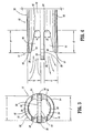
- the angular orientations of planar end surfaces 54, 60 ( ⁇ , ⁇ ) cause cavities 56, 62 to direct fluid in the direction shown by the arrows in FIGURE 4 .
- catheter 10 advantageously facilitates reversible flow between first lumen 16 and second lumen 18 such that, for example, blood clots attaching to catheter 10, including septum 20, may be washed away by alternating blood flow directions.
- second lumen 18 expels blood flow for introduction to the body vessel, blood flow is forced out of second lumen 18.
- the blood flow is axially directed out of cavity 62 past second wall extension 32. It is envisioned that such axially directed blood flow washes away any blood clots disposed adjacent cavity 62.
- fluid flow exiting second lumen 18 may wash other particles undesirably attached to catheter 10. This configuration prevents undesirable recirculation of fluid flow between second lumen 18 and first lumen 16. Thus, blood clots, etc.
- catheter 10 attached to catheter 10, including septum 20 may be washed away by alternating and/or reversing flow directions with consecutive dialysis. It is contemplated that the alternating and/or reversible flow may be provided by a source outside the body of catheter 10 such as, for example, a dialysis machine, etc. connected thereto.
- First lumen 16 is provided with suction to withdraw fluids from the body vessel. Efficiency of fluid inflow through cavity 56 to first lumen 16 is improved due to the configuration of cavity 56 and consequent fluid direction. It is contemplated that blood clots, or other undesired particles, disposed adjacent cavity 56 of first lumen 16 may be washed away by reversing blood flow direction of lumens 16, 18 with consecutive dialysis procedures. Upon reversal of blood flow direction, blood flow is expelled from cavity 56 and the axially directed blood flow washes away blood clots, similar to that described above. Second lumen 18 is provided with suction to withdraw fluids from the body vessel and into opening 50.
- first wall extension 28 and second wall extension 32 supports a vessel wall of a body vessel (not shown). This configuration spaces the vessel wall from inlet opening 46 and outlet opening 50 to prevent vessel wall occlusion of openings 46, 50 during for example, suction through the lumens. It is further envisioned that first wall extension 28 and second wall extension 32 may have sufficient thickness and/or be fabricated from semi-rigid or rigid materials to prevent undesired deformation thereof.
- First wall 22 includes a first wall extension 228 that extends distally beyond first lumen 16 and is spaced apart from septum extension 26.
- First wall extension 228 defines a concave surface 230 that faces septum extension 26.
- Second wall 24 includes a second wall extension 232 that extends distally beyond second lumen 18 and is spaced apart from septum extension 26.
- Second wall extension 32 defines a concave surface 234 that faces septum extension 26.
- First wall extension 228 includes a first step 212 and a second step 214 formed therewith.
- First step 212 is formed with septum extension 26.
- First step 212 and second step 214 are circumferentially disposed about septum extension 26. It is envisioned that first step 212 and/or second step 214 may have alternate configurations, such as, for example, planar, etc.
- First step 212 extends distally, a distance aa , beyond inlet opening 46 of first lumen 16 and outlet opening 50 of second lumen 18.
- Second step 214 extends distally a distance bb, beyond inlet opening 46 and outlet opening 50. It is contemplated that distance aa and bb may extend various lengths.
- Concave surface 230 faces first planar surface 52 of septum extension 26 and is spaced apart therefrom. Concave surface 230 spans across approximately one-quarter of the circumference of body 12 or a substantially 90° arc as extended from septum extension 26. It is envisioned that first step 212 and/or second step 214, or other portions of concave surface 230 may be variously disposed about body 12.
- Concave surface 230 is bounded by a planar end surface 254 of first wall extension 228. End surface 254 extends about the perimeter of concave surface 230 to facilitate fluid flow through first lumen 16. Concave surface 230 and first planar surface 52 cooperate to define first cavity 56, similar to that described above. First cavity 56 is further bounded by a proximal base 264. Proximal base 264 defines a proximal inlet portion for first lumen 16 during withdrawal of fluids. It is contemplated that suction provided with first lumen 16 has a greater fluid flow rate adjacent proximal base 264.
- Second wall extension 232 includes a first step 216 and a second step 218 formed therewith.
- First step 216 is formed with septum extension 26.
- First step 216 and second step 218 are circumferentially disposed about septum extension 26. It is contemplated that first step 216 and/or second step 218 may have alternate configurations, such as, for example, planar, etc.
- First step 216 extends distally, a distance dd , beyond outlet opening 50 and inlet opening 46.
- Second step 218 extends distally a distance ee, beyond inlet opening 46 and outlet opening 50. It is contemplated that distances dd and ee may extend various lengths.
- Concave surface 234 faces second planar surface 58 of septum extension 26, opposing first planar surface 52, and is spaced apart therefrom. Concave surface 234 spans across approximately one-quarter of the circumference of body 12 or a substantially 90° arc, as extended from septum extension 26. It is envisioned that first step 216 and/or second step 218, or other portions of concave surface 234 may be variously disposed about body 12.
- Concave surface 234 is bounded by a planar end surface 260 of second wall extension 232. End surface 260 extends about the perimeter of concave surface 234 to facilitate fluid flow through second lumen 18. Concave surface 234 and second planar surface 58 cooperate to define second cavity 62, similar to that described above. Second cavity 62 is further bounded by a proximal base 266. For example, if fluid flow is reversed with catheter 10, proximal base 266 defines a proximal inlet portion for second lumen 18 during withdrawal of fluids. It is contemplated that suction provided with second lumen 18 has a greater fluid flow rate adjacent proximal base 266.
- First wall extension 228 and second wall extension 232 are symmetrically disposed about septum extension 26 such that first cavity 56 and second cavity 62 are symmetrical.
- First cavity 56 and second cavity 62 bound an equivalent space to facilitate inflow and outflow capability for each lumen.
- catheter 10 advantageously facilitates reversible flow between first lumen 16 and second lumen 18 such that, for example, blood clots attaching to catheter 10 may be washed away by alternating blood flow directions.
- second lumen 18 expels blood flow for introduction to the body vessel, blood flow is forced out of second lumen 18.
- the blood flow is axially directed out of cavity 62 past second wall extension 232. It is envisioned that such axially directed blood flow washes away any blood clots disposed adjacent cavity 62. It is further envisioned that fluid flow exiting second lumen 18 may wash other particles undesirably attached to catheter 10.
- First lumen 16 is provided with suction to withdraw fluids from the body vessel.
- the suction draws blood flow from various directions and orientations into inlet opening 46.
- Suction is greater adjacent proximal base 264 due to its closer proximity to a suction source (not shown). Fluid flow is greater adjacent to proximal base 264 and therefore, advantageously disposed proximal to the blood flow being expelled from cavity 62 of second lumen 18. This configuration minimizes recirculation between lumens 16, 18.
- blood clots, or other undesired particles, disposed adjacent cavity 56 of first lumen 16 may be washed away by reversing blood flow direction of lumens 16, 18. Upon reversal of blood flow direction, blood flow is expelled from cavity 56 and the axially directed blood flow washes away blood clots, similar to that described above.
- Second lumen 18 is provided with suction to withdraw fluids from the body vessel and into opening 50.
- Second wall extension 232 is symmetrical with first wall extension 228, and therefore, similar to proximal base 264, suction is greater adjacent proximal base 266. Fluid flow is greater adjacent to proximal base 266 and therefore, advantageously disposed proximal to the blood flow being expelled from cavity 56. This configuration minimizes recirculation between lumens 16, 18.
- First wall 22 includes a first wall extension 328 that extends distally beyond first lumen 16 and is spaced apart from septum extension 26.
- First wall extension 328 defines a concave surface 330 that faces septum extension 26.
- Second wall 24 includes a second wall extension 332 that extends distally beyond second lumen 18 and is spaced apart from septum extension 26.
- Second wall extension 32 defines a concave surface 334 that faces septum extension 26.
- First wall extension 328 includes a first step 312 and a second step 314 formed therewith in an arcuate transition.
- First step 312 is formed with septum extension 26 in an arcuate transition.
- First step 312 and second step 314 are circumferentially disposed about septum extension 26. It is envisioned that first step 312 and/or second step 314 may have alternate configurations, such as, for example, planar, etc.
- First step 312 extends distally, a distance aa , beyond inlet opening 46 of first lumen 16 and outlet opening 50 of second lumen 18.
- Second step 314 extends distally a distance bb , beyond inlet opening 46 and outlet opening 50. It is contemplated that distance aa and bb may extend various lengths.
- Concave surface 330 faces first planar surface 52 of septum extension 26 and is spaced apart therefrom. Concave surface 330 spans across approximately one-quarter of the circumference of body 12 or a substantially 90° arc as extended from septum extension 26. It is envisioned that first step 312 and/or second step 314, or other portions of concave surface 330 may be variously disposed about body 12.
- Concave surface 330 is bounded by a planar end surface 354 of first wall extension 328. End surface 354 extends about the perimeter of concave surface 330 to facilitate fluid flow through first lumen 16. Concave surface 330 and first planar surface 52 cooperate to define first cavity 56, similar to that described above. First cavity 56 is further bounded by a proximal base 364. Proximal base 364 has an arcuate configuration and defines a proximal inlet portion for first lumen 16 during withdrawal of fluids. It is contemplated that suction provided with first lumen 16 has a greater fluid flow rate adjacent proximal base 364.
- Second wall extension 332 includes a first step 316 and a second step 318 formed therewith in an arcuate transition.
- First step 316 is formed with septum extension 26.
- First step 316 and second step 318 are circumferentially disposed about septum extension 26. It is contemplated that first step 316 and/or second step 318 may have alternate configurations, such as, for example, planar, etc.
- First step 316 extends distally, a distance dd , beyond outlet opening 50 and inlet opening 46.
- Second step 318 extends distally a distance ee , beyond inlet opening 46 and outlet opening 50. It is contemplated that distances dd and ee may extend various lengths.
- Concave surface 334 faces second planar surface 58 of septum extension 26, opposing first planar surface 52, and is spaced apart therefrom. Concave surface 334 spans across approximately one-quarter of the circumference of body 12 or a substantially 90° arc, as extended from septum extension 26. It is envisioned that first step 316 and/or second step 318, or other portions of concave surface 334 may be variously disposed about body 12.
- Concave surface 334 is bounded by a planar end surface 360 of second wall extension 332. End surface 360 extends about the perimeter of concave surface 334 to facilitate fluid flow through second lumen 18. Concave surface 334 and second planar surface 58 cooperate to define second cavity 62, similar to that described above. Second cavity 62 is further bounded by a proximal base 366. For example, if fluid flow is reversed with catheter 10, proximal base 366 has an arcuate configuration and defines a proximal inlet portion for second lumen 18 during withdrawal of fluids. It is contemplated that suction provided with second lumen 18 has a greater fluid flow rate adjacent proximal base 366.
- First wall extension 328 and second wall extension 332 are symmetrically disposed about septum extension 26 such that first cavity 56 and second cavity 62 are symmetrical.
- First cavity 56 and second cavity 62 bound an equivalent space to facilitate inflow and outflow capability for each lumen.
- catheter 10 advantageously facilitates reversible flow between first lumen 16 and second lumen 18 by alternating blood flow directions.
- second lumen 18 expels blood flow for introduction to the body vessel, blood flow is forced out of second lumen 18.
- the blood flow is axially directed out of cavity 62 past second wall extension 332. It is envisioned that such axially directed blood flow washes away any blood clots disposed adjacent cavity 62.
- First lumen 16 is provided with suction to withdraw fluids from the body vessel.
- the suction draws blood flow from various directions and orientations into inlet opening 46.
- Suction is greater adjacent proximal base 364 due to its closer proximity to a suction source (not shown). Fluid flow is greater adjacent to proximal base 364 and therefore, advantageously disposed proximal to the blood flow being expelled from cavity 62 of second lumen 18. This configuration minimises recirculation between lumens 16, 18.
- blood clots, or other undesired particles, disposed adjacent cavity 56 of first lumen 16 may be washed away by reversing blood flow direction of lumens 16, 18. Upon reversal of blood flow direction, blood flow is expelled from cavity 56 and the axially directed blood flow washes away blood clots, similar to that described above.
- Second lumen 18 is provided with suction to withdraw fluids from the body vessel and into opening 50.
- Second wall extension 332 is symmetrical with first wall extension 328, and therefore, similar to proximal base 364, suction is greater adjacent proximal base 366. Fluid flow is greater adjacent to proximal base 366 and therefore, advantageously disposed proximal to the blood flow being expelled from cavity 56. This configuration minimises recirculation between lumens 16, 18.
- First wall 22 includes a first wall extension 428 that extends distally beyond first lumen 16 and is spaced apart from septum extension 26.
- First wall extension 428 defines a concave surface 430 that faces septum extension 26.
- Second wall 24 includes a second wall extension 432 that extends distally beyond second lumen 18 and is spaced apart from septum extension 26.
- Second wall extension 432 defines a concave surface 434 that faces septum extension 26.
- First wall extension 428 is circumferentially disposed about septum extension 26 in a spiral configuration to facilitate fluid flow and prevent recirculation between lumens 16,18. It is envisioned that first wall extension 428 may include various spiral configurations, such as, for example, a more elongated spiral, a spiral having a more acute winding type design, helical, etc. First wall extension 428 extends distally, a distance aaa, beyond inlet opening 46 of first lumen 16 and outlet opening 50 (shown in phantom) of second lumen 18. It is contemplated that distance aaa may extend various lengths. Concave surface 430 faces first planar surface 52 of septum extension 26 and is spaced apart therefrom.
- Concave surface 430 is bounded by a planar end surface 454 of first wall extension 428. End surface 454 extends about the perimeter of concave surface 430 in a spiral configuration, as described above, to facilitate fluid flow through first lumen 16. Concave surface 430 and first planar surface 52 cooperate to define first cavity 56, similar to that described above. First cavity 56 is further bounded by a proximal base 464 of end surface 454. Proximal base 464 is formed with septum extension 26 in an arcuate transition. Proximal base 464 has an arcuate configuration and defines a proximal inlet portion for first lumen 16 during withdrawal of fluids. It is contemplated that suction provided with first lumen 16 has a greater fluid flow rate adjacent proximal base 464.
- Second wall extension 432 is circumferentially disposed about septum extension 26 in a spiral configuration to facilitate fluid flow and prevent recirculation between lumens 16,18. It is envisioned that first wall extension 432 may include various spiral configurations, such as, for example, a more elongated spiral, a spiral having a more acute winding type design, helical, etc. Second wall extension 432 extends distally, a distance bbb, beyond outlet opening 50 (shown in phantom and similarly configured to inlet opening 46) and inlet opening 46. It is contemplated that distance bbb may extend various lengths. Concave surface 434 faces second planar surface 58, opposing first planar surface 52, of septum extension 26 and is spaced apart therefrom.
- Concave surface 434 is bounded by a planar end surface 460 of second wall extension 432.
- End surface 460 (similarly configured to end surface 454, although end surfaces 454,460 may include alternative or distinct structure) extends about the perimeter of concave surface 434 in a spiral configuration, as described above, to facilitate fluid flow through second lumen 18.
- Concave surface 434 and second planar surface 58 cooperate to define second cavity 62 (shown in phantom), similar to that described above.
- Second cavity 62 is further bounded by a proximal base 466 of end surface 460 (shown in phantom and similarly configured to base 464, although bases 464,466 may include alternative or distinct structure).
- proximal base 466 has an arcuate configuration and defines a proximal inlet portion for second lumen 18 during withdrawal of fluids. It is contemplated that suction provided with second lumen 18 has a greater fluid flow rate adjacent proximal base 466.
- First wall extension 428 and second wall extension 432 are symmetrically disposed about septum extension 26 such that first cavity 56 and second cavity 62 are symmetrical.
- First cavity 56 and second cavity 62 bound an equivalent space to facilitate inflow and outflow capability for each lumen.
- catheter 10 advantageously facilitates reversible flow between first lumen 16 and second lumen 18 by alternating blood flow directions.
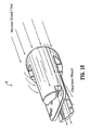
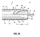
- second lumen 18 expels blood flow for introduction to the body vessel (shown by arrows A in FIG. 19 ), blood flow is forced out of second lumen 18.
- the blood flow is axially directed out of cavity 62 past second wall extension 432. It is envisioned that such axially directed blood flow washes away any blood clots disposed adjacent cavity 62.
- First lumen 16 is provided with suction to withdraw fluids from the body vessel.
- the suction draws blood flow from various directions and orientations into inlet opening 46 (shown by arrows B in FIG. 19 ).
- Suction is greater adjacent proximal base 464 due to its closer proximity to a suction source (not shown). Fluid flow is greater adjacent to proximal base 464 and therefore, advantageously disposed proximal to the blood flow being expelled from cavity 62 of second lumen 18. This configuration minimizes recirculation between lumens 16, 18.
- blood clots, or other undesired particles, disposed adjacent cavity 56 of first lumen 16 may be washed away by reversing blood flow direction of lumens 16, 18. Upon reversal of blood flow direction, blood flow is expelled from cavity 56 and the axially directed blood flow washes away blood clots, similar to that described above.
- Second lumen 18 is provided with suction to withdraw fluids from the body vessel and into opening 50.
- Second wall extension 432 is symmetrical with first wall extension 428, and therefore, similar to proximal base 464, suction is greater adjacent proximal base 466. Fluid flow is greater adjacent to proximal base 466 and therefore, advantageously disposed proximal to the blood flow being expelled from cavity 56. This configuration minimizes recirculation between lumens 16, 18.
Landscapes
- Health & Medical Sciences (AREA)
- Life Sciences & Earth Sciences (AREA)
- Heart & Thoracic Surgery (AREA)
- Animal Behavior & Ethology (AREA)
- Public Health (AREA)
- Engineering & Computer Science (AREA)
- Anesthesiology (AREA)
- Biomedical Technology (AREA)
- Hematology (AREA)
- Veterinary Medicine (AREA)
- General Health & Medical Sciences (AREA)
- Vascular Medicine (AREA)
- Biophysics (AREA)
- Pulmonology (AREA)
- Urology & Nephrology (AREA)
- Cardiology (AREA)
- Emergency Medicine (AREA)
- External Artificial Organs (AREA)
- Media Introduction/Drainage Providing Device (AREA)
- Materials For Medical Uses (AREA)
Abstract
Description
- The present disclosure relates generally to medical catheter apparatus, and more particularly to a catheter including a catheter tip that prevents occlusion during use.
- Some known catheters are tubular, flexible medical devices for administration of fluids (withdrawal, introduction, etc) within cavities, ducts, vessels, etc. of a body.
- These catheter devices may be employed for administration of fluids that includes the simultaneous introduction and withdrawal of fluid for applications such as, surgery, treatment, diagnosis, etc. In one particular haemodialysis application, blood is withdrawn from a blood vessel for treatment by an artificial kidney device and the treated blood is introduced back into the blood vessel.
- Various known catheter devices have been employed for simultaneous withdrawal and introduction of fluid with a body. These devices may utilise multiple lumens, such as dual lumen catheters that facilitate bi-directional fluid flow whereby one lumen performs withdrawal of blood and the other lumen introduces treated blood to the vessel. During an exemplary haemodialysis procedure, a multiple lumen catheter is inserted into a body and blood is withdrawn through an arterial lumen of the catheter. This blood is supplied to a haemodialysis unit which dialyses, or cleans, the blood to remove waste and excess water. The dialysed blood is returned to the patient through a venous lumen of the catheter. Typically, the venous lumen is separated from the arterial lumen by an inner catheter wall, called a septum.
- The efficiency of a haemodialysis procedure may be reduced by undesirable recirculation of blood flow whereby the dialysed blood exiting the venous lumen is directly returned to the arterial lumen. To overcome this drawback some catheter devices stagger the openings of the lumens such that the opening of the venous lumen is disposed distally beyond the opening of the arterial lumen.
- These catheter devices, however, also suffer from various additional drawbacks. For example, blood clots can form adjacent to or on the opening of both lumens and at locations between the openings of the lumens. Another drawback that may arise, due to the dedicated flow direction for a particular lumen, is recirculation if the flow direction is reversed. Further, suction introduced through lumen openings of the prior art may draw portions of a body vessel wall therein. These drawbacks can disadvantageously result in flow occlusion.
- Therefore, it would be desirable to overcome the disadvantages and drawbacks of the prior art with a catheter including a catheter tip that prevents occlusion during use to facilitate unobstructed fluid flow. It would be desirable if such a catheter included concave surfaces adjacent the catheter tip to prevent occlusion and undesirable recirculation. The catheter may also facilitate reversible flow between lumens of the catheter. It would be highly desirable if the catheter and its constituent parts are easily and efficiently manufactured and assembled.
- Known catheters are described in
WO 95/10317 US-A-2541691 ,FR-A-2326941 US-A-5571093 ,WO 2004/096334 andUS 5961486 , the latter disclosing the features of the preamble of claim 1. - The present invention provides a catheter comprising:
- an elongate tubular body defining a longitudinal axis and extending to a distal end thereof, the tubular body having a first lumen and a second lumen with a septum disposed therebetween, the tubular body including a first wall that defines the first lumen and a second wall that defines the second lumen, a portion of the septum extending distally beyond the first lumen and the second lumen;
- wherein the first wall includes a first wall extension that extends in a spiral configuration from the first lumen about the longitudinal axis, and is spaced apart from said portion of the septum.
- Accordingly, a catheter is provided including a catheter tip that prevents occlusion during use to facilitate unobstructed fluid flow to overcome the disadvantages and drawbacks of the prior art. Desirably, such a catheter includes concave surfaces adjacent the catheter tip to prevent occlusion and undesirable recirculation. The catheter may also facilitate reversible flow between lumens of the catheter. Most desirably, the catheter is easily and efficiently manufactured and assembled. The present disclosure resolves related disadvantages and drawbacks experienced in the art.
- The present disclosure provides, among other things, a multiple lumen dialysis catheter with a tip configuration such that the distal ends of the lumens terminate in symmetrical angled relationships. Distal wall extensions of the lumens are at the same longitudinal position along the catheter. The catheter may include sideholes.
- Thus, the catheter tip configuration of the present disclosure advantageously reduces the potential for positional occlusion. The design of the catheter tip helps to keep the tip away from the sidewall of the vessel, eliminating the potential for the catheter to adhere to the vessel wall when suction is applied.
- The symmetrical catheter tip design also advantageously facilitates the capability of bi-directional fluid flow for each lumen of the catheter. The symmetrical configuration of the catheter tip overcomes the disadvantages of dedicating a particular lumen to a flow direction, such as, for example, inflow, outflow, etc. This configuration results in similar recirculation in either direction of the blood flow (inflow lumen used for inflow and outflow lumen used for outflow, or outflow lumen used for inflow and inflow lumen used for outflow). Thus, blood clots attached to the catheter, including the septum may be washed away by alternating and/or reversing flow directions with consecutive dialysis. It is contemplated that the alternating and/or reversible flow may be provided by a source outside the body of the catheter such as, for example, a dialysis machine, etc. connected thereto.
- In one particular embodiment, a catheter is provided, in accordance with the principles of the present disclosure. The catheter includes an elongated tubular body extending to a distal end thereof. The tubular body has a first lumen and a second lumen with a septum disposed therebetween. The tubular body includes a first wall that defines the first lumen and a second wall that defines the second lumen. A portion of the septum extending distally beyond the first lumen and the second lumen. The first wall includes a first wall extension that extends distally beyond the first lumen and is spaced apart from the portion of the septum. The first wall extension defines a concave surface facing the portion of the septum.
- The portion of the septum may define a planar surface that faces the concave surface of the first wall extension. The first wall extension may include a planar end surface that forms a boundary about the concave surface of the first wall extension. The planar end surface can be disposed at an angular orientation relative to a planar surface of the portion of the septum that faces the concave surface of the first wall extension.
- Alternatively, the second wall includes a second wall extension that extends distally beyond the second lumen and is spaced apart from the portion of the septum. The second wall extension defines a concave surface facing the portion of the septum. The portion of the septum may define a planar surface that faces the concave surface of the second wall extension. The second wall extension may include a planar end surface that forms a boundary about the concave surface of the second wall extension. The planar end surface can be disposed at an angular orientation relative to a planar surface of the portion of the septum that faces the concave surface of the second wall extension.
- The concave surface of the first wall extension may define a first cavity and the concave surface of the second wall extension may define a second cavity. The first cavity and the second cavity are symmetrical. The first wall extension and the second wall extension may be symmetrically disposed about the portion of the septum. The first wall extension may include a first step extending a first distance beyond the first lumen and a second step extending a second distance beyond the first lumen. The second wall extension may include a first step extending a first distance beyond the second lumen and a second step extending a second distance beyond the second lumen.
- In an alternate embodiment, the septum has a septum extension disposed adjacent to a distal tip of the catheter and extends distally beyond the first lumen and the second lumen. The first wall extends distally beyond the first lumen and is spaced apart from the septum extension. The first wall extension defines a concave surface facing the septum extension. The second wall extends distally beyond the second lumen and is spaced apart from the septum extension. The second wall extension defines a concave surface facing the septum extension.
- In another alternate embodiment, the septum extension defines a first planar surface and an opposing second planar surface. The first wall includes a first wall extension that extends distally beyond the first lumen and the second lumen. The first wall is spaced apart from the septum extension. The first wall extension defines a concave surface facing the first planar surface of the septum extension and is bounded by a planar end surface of the first wall extension. The planar end surface of the first wall extension is disposed at an angular orientation relative to the first planar surface of the septum extension. The second wall includes a second wall extension that extends distally beyond the first lumen and the second lumen. The second wall is spaced apart from the septum extension. The second wall extension defines a concave surface facing the second planar surface of the septum extension and is bounded by a planar end surface of the second wall extension. The planar end surface of the second wall extension is disposed at an angular orientation relative to the second planar surface of the septum extension.
- In another alternate embodiment, the concave surface of the first wall extension defines a first cavity and the concave surface of the second wall extension defines a second cavity. The first wall extension includes a first base that defines an inlet opening of the first cavity. The first base is disposed proximal to fluid flow being expelled from the second wall extension. The second wall extension may include a second base that defines an inlet opening of the second cavity. The second base is disposed proximal to fluid flow being expelled from the first cavity of the second wall extension. The first base and/or the second base may have an arcuate configuration.
- In another alternative embodiment, the first wall includes a first wall extension that extends in a spiral configuration from the first lumen and is spaced apart from the portion of the septum. The second wall may include a second wall extension that extends in a spiral configuration from the second lumen and is spaced apart from the portion of the septum. The first wall extension may include a planar end surface that forms a boundary about the first wall extension and defines the spiral configuration of the first wall extension. The second wall extension may include a planar end surface that forms a boundary about the second wall extension and defines the spiral configuration of the second wall extension.
- The aims and features of the present invention, which are believed to be novel, are set forth with particularity in the claims. The present invention, both as to its organisation and manner of operation, together with further aims and advantages, may be best understood by reference to the following description, taken in connection with the accompanying drawings, as set forth below.
-
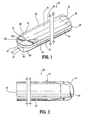
Figure 1 is a perspective view of a catheter which is not falling within the scope of the invention, showing a septum in phantom; -
Figure 2 is a side view of a distal end of the catheter shown inFigure 1 ; -
Figure 3 is a front view of the catheter shown inFigure 1 ; -
Figure 4 is an enlarged side view of the distal end of the catheter shown inFigure 1 ; -
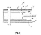
Figure 5 is an enlarged side view of an alternative form of the distal end of the catheter shown inFigure 1 ; -
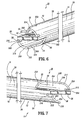
Figure 6 is an enlarged perspective view of another alternative form of the catheter shown inFigure 1 ; -
Figure 7 is an enlarged alternate perspective view of the catheter shown inFigure 6 ; -
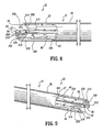
Figure 8 is an enlarged alternate perspective view of the catheter shown inFigure 6 ; -
Figure 9 is an enlarged alternate perspective view of the catheter shown inFigure 6 ; -
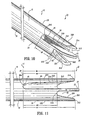
Figure 10 is a perspective view of another alternative form of the catheter shown inFigure 1 ; -
Figure 11 is a side view of the catheter shown inFigure 10 ; -
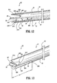
Figure 12 is an alternative perspective view of the catheter shown inFigure 10 ; -
Figure 13 is an alternative perspective view of the catheter shown inFigure 10 ; -
Figure 14 is an alternative perspective view of the catheter shown inFigure 10 ; -
Figure 15 is an alternative side view of the catheter shown inFigure 10 ; -
Figure 16 is a perspective view of the catheter shown inFigure 10 , illustrating fluid flow; -
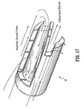
Figure 17 is a perspective view of the catheter shown inFigure 10 , illustrating fluid flow; -
Figure 18 is a perspective side view of the catheter shown inFigure 10 , illustrating fluid flow; -
Figure 19 is a perspective view of a catheter constructed according to the invention, the catheter being a modified form of that shown inFigure 1 ; -
Figure 20 is a side view of the catheter shown inFigure 19 ; and -
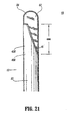
Figure 21 is an alternative side view of the catheter shown inFigure 19 . - The exemplary forms of the catheter and methods of use disclosed are discussed in terms of medical catheters for the administration of fluids (withdrawal, introduction, etc.) with the body of a subject and more particularly, in terms of a catheter including a catheter tip that prevents occlusion during use to facilitate unobstructed fluid flow. The catheter is advantageously configured to facilitate reversible fluid flow between lumens thereof. It is envisioned that the present disclosure may be employed with a range of catheters, such as, for example, hemodialysis, peritoneal, infusion, PICC, CVC, port, etc. and catheter applications including surgical, diagnostic and related treatments of diseases, body ailments, etc. of a subject. It is further envisioned that the principles relating to the catheter disclosed include employment with various catheter related procedures, such as, for example, hemodialysis, cardiac, abdominal, urinary, intestinal, etc., in chronic, acute, etc. applications. It is contemplated that the catheter can be used for administration of fluids such as, for example, medication, saline, bodily fluids such as, blood, urine, etc. The catheter may also be used to monitor subject condition.
- In the discussion that follows, the term "proximal" will refer to the portion of a structure that is closer to a practitioner, while the term "distal" will refer to the portion that is further from the practitioner. As used herein, the term "subject" refers to a human patient or other animal. According to the present disclosure, the term "practitioner" refers to a doctor, nurse or other care provider and may include support personnel.
- The following discussion includes a description of the catheter, in accordance with the principles of the present disclosure. Reference will now be made in detail to the exemplary embodiments of the disclosure, which are illustrated in the accompanying figures.
- Turning now to the figures, wherein like components are designated by like reference numerals throughout the several views.
Figures 1-18 show illustrative examples not falling within the scope of the invention. Referring initially toFIGURES 1-4 , acatheter 10 includes an elongatedtubular body 12 that extends to adistal end 14.Body 12 has afirst lumen 16 and asecond lumen 18, with aseptum 20 disposed therebetween.Body 12 includes afirst wall 22 that definesfirst lumen 16 and asecond wall 24 that definessecond lumen 18. A portion, such as, for example,septum extension 26 ofseptum 20 extends distally beyondfirst lumen 16 andsecond lumen 18.Septum 20 is medially disposed, along a substantial portion of the longitudinal length ofbody 12, betweenfirst lumen 16 andsecond lumen 18.Septum 20 may be variously disposed withbody 12, such as, for example, angularly offset relative to extended portions of the first and second walls, etc. -
First wall 22 includes afirst wall extension 28 that extends distally beyondfirst lumen 16 and is spaced apart fromseptum extension 26.First wall extension 28 defines aconcave surface 30 that facesseptum extension 26.Second wall 24 includes asecond wall extension 32 that extends distally beyondsecond lumen 18 and is spaced apart fromseptum extension 26.Second wall extension 32 defines aconcave surface 34 that facesseptum extension 26. -
Septum extension 26 extends beyondfirst wall extension 28 andsecond wall extension 32.Septum extension 26 is medially disposed, as extending frombody 12, betweenfirst wall extension 28 andsecond wall extension 32.Septum extension 26 may be variously disposed for extension frombody 12. The disclosed configuration ofcatheter 10 advantageously prevents occlusion offirst lumen 16 andsecond lumen 18, as will be discussed. One or a plurality of wall extensions may be employed withcatheter 10, according to the particular requirements of a catheter application. -
Body 12 has a cylindricalouter surface 36. It is contemplated thatbody 12 may be variously dimensioned and attachable to other medical devices. It is further contemplated thatouter surface 36 may have various cross-sectional configurations, such as, for example, oval, rectangular, elliptical, polygonal, etc.Body 12 may also include lateral openings.First wall 22 has awall surface 38 that definesfirst lumen 16 in cooperation with asurface 40 ofseptum 20.Second wall 24 has awall surface 42 that definessecond lumen 18 in cooperation with asurface 44 ofseptum 20. -
Lumens Lumens body 12 and surfaces 38,40,42,44 are configured to facilitate fluid flow withinlumens lumens lumens -
Lumens body 12, such as, narrow and broad portions, converging surfaces, undulating surfaces, etc. according to the particular flow indications and/or flow rate requirements. It is contemplatedlumen 16 andlumen 18 may extend alternative lengths. It is further contemplated thatbody 12 may include one or a plurality of lumens, such as, for example, a triple lumen configuration, etc. -
First lumen 16 includes a first opening, such as, for example, aninlet opening 46 that is disposed adjacent todistal end 14 ofbody 12. An outlet opening (not shown) offirst lumen 16 is disposed adjacent aproximal end 48 ofbody 12.Inlet opening 46 is configured for suction and may be inserted with a blood vessel of a subject (not shown) such that blood is withdrawn, by for example, arterial blood flow in a first direction, from the blood vessel for treatment by an artificial kidney device (not shown).Inlet opening 46 may be variously dimensioned and configured, such as, for example, rectangular, elliptical, polygonal, etc. and may include adapters, clips, etc. to facilitate fluid flow and/or attachment to other structure. It is contemplated that inlet opening 46 may be configured for expulsion of fluid. -
First lumen 16 is separated fromsecond lumen 18 byseptum 20.Second lumen 18 includes a second opening, such as, for example, anoutlet opening 50 that is disposed adjacent todistal end 14 and in substantial longitudinal alignment, alongbody 12, withinlet opening 46. An inlet opening (not shown) ofsecond lumen 18 is disposed adjacentproximal end 48.Outlet opening 50 is configured for expulsion of fluid and introduces the treated blood from the artificial kidney device back into the blood vessel, by for example, venous blood flow in a second opposite direction.Outlet opening 50 may be variously dimensioned and configured, such as, for example, rectangular, elliptical, polygonal, etc. and may include adapters, clips, etc. to facilitate fluid flow and/or attachment to other structure. It is contemplated that outlet opening 50 may be configured for withdrawal of fluid. - The components of
catheter 10 are fabricated from materials suitable for medical applications, such as, for example, polymerics or metals, such as stainless steel, depending on the particular catheter application and/or preference of a practitioner. Semi-rigid and rigid polymerics are contemplated for fabrication, as well as resilient materials, such as molded medical grade polypropylene. One skilled in the art, however, will realize that other materials and fabrication methods suitable for assembly and manufacture, in accordance with the present disclosure, also would be appropriate. -
First wall extension 28 extends distally, a distance a, beyond inlet opening 46 offirst lumen 16 and outlet opening 50 ofsecond lumen 18. It is contemplated that distance a may extend various lengths according to the requirements of a particular catheter application, such as, for example, approximately 0,003-0,005 cm (.100-.200 inches).Concave surface 30 faces a firstplanar surface 52 ofseptum extension 26 and is spaced apart therefrom a distance b. It is contemplated that distance b may extend various lengths. It is further contemplated thatsurface 52 may be non-planar, such as, for example, arcuate, undulating, textured, etc. -
Concave surface 30 is bounded by aplanar end surface 54 offirst wall extension 28 and spans a radial distance c.End surface 54 extends about the perimeter ofconcave surface 30 such thatfirst wall extension 28 has a scoop-like configuration that facilitates fluid flow throughfirst lumen 16. It is contemplated thatfirst wall extension 28 may form alternate configurations, such as, for example, spherical, rectangular, etc.End surface 54 includes aradial portion 55 adjacent a distal end offirst wall extension 28.Radial portion 55 extends to the longitudinally orientedouter surface 36 ofbody 12 in an arcuate configuration. This configuration advantageously prevents a vessel wall (not shown) from becoming disposed within the inlet offirst lumen 16. In an alternate embodiment, as shown inFIGURE 5 , aradial portion 155 extends to the longitudinally oriented outer surface 3 6 ofbody 12 in a perpendicular convergence. - It is contemplated that distance c may extend various lengths.
Planar end surface 54 is disposed at an angular orientation α relative to firstplanar surface 52. It is envisioned thatend surface 54 may be disposed at various angular orientations α, such as, for example, 5-20 degrees. -
Concave surface 30 and firstplanar surface 52 cooperate to define afirst cavity 56.First cavity 56 is disposed distally beyondinlet opening 46.First cavity 56 is dimensioned and configured according to the bounds of one or all of inlet opening 46,concave surface 30,planar end surface 54 andseptum extension 26, according to the particular requirements of a catheter application. The extension offirst cavity 56 distally beyond inlet opening 46 prevents undesirable recirculation of fluid flow betweenfirst lumen 16 andsecond lumen 18 as facilitated by the barrier provided byseptum extension 26. -
Second wall extension 32 extends distally, a distance d, beyond outlet opening 50 ofsecond lumen 18 and inlet opening 46 offirst lumen 16. It is contemplated that distance d may extend various lengths according to the requirements of a particular catheter application, such as, for example, approximately 0,003-0,005 cm (.100-.200 inches).Concave surface 34 faces a secondplanar surface 58 ofseptum extension 26, opposing firstplanar surface 52, and is spaced apart therefrom a distance e. - It is contemplated that distance e may extend various lengths. It is further contemplated that
surface 58 may be non-planar, such as, for example, arcuate, undulating, textured, etc. It is envisioned thatsurface 52 may be disposed at angular orientations relative tosurface 58. -
Concave surface 34 is bounded by aplanar end surface 60 ofsecond wall extension 32 and spans a radial distance f.End surface 60 extends about the perimeter ofconcave surface 34 such thatsecond wall extension 32 has a scoop-like configuration that facilitates fluid flow throughsecond lumen 18. It is envisioned thatsecond wall extension 32 may form alternate configurations, such as, for example, spherical, rectangular, etc.End surface 60 includes aradial portion 61 adjacent a distal end ofsecond wall extension 32.Radial portion 61 extends to the longitudinally orientedouter surface 36 ofbody 12 in an arcuate configuration. This configuration advantageously prevents, for example, a vessel wall (not shown) from becoming disposed within the distal opening ofsecond lumen 18 in the event fluid is reversed and suction is provided for withdrawal of fluid therethrough. In an alternate example, as shown inFIGURE 5 , aradial portion 161 extends to the longitudinally orientedouter surface 36 in a perpendicular intersection. - It is contemplated that distance f may extend various lengths.
Planar end surface 60 is disposed at an angular orientation β relative to secondplanar surface 58. It is envisioned thatend surface 60 may be disposed at various orientations β, such as, for example, 5-20 degrees. -
Concave surface 34 and secondplanar surface 58 cooperate to define asecond cavity 62.Second cavity 62 is disposed distally beyondoutlet opening 50.Second cavity 62 is dimensioned and configured according to the bounds of one or all ofoutlet opening 50,concave surface 34,planar end surface 60 andseptum extension 26, according to the particular requirements of a catheter application. The extension ofsecond cavity 62 distally beyond outlet opening 50 prevents undesirable recirculation of fluid flow betweensecond lumen 18 andfirst lumen 16 as facilitated by the barrier provided byseptum extension 26. -
First wall extension 28 andsecond wall extension 32 are symmetrically disposed aboutseptum extension 26 such thatfirst cavity 56 andsecond cavity 62 are symmetrical.First cavity 56 andsecond cavity 62 bound an equivalent space to facilitate inflow and outflow capability for each lumen. The space bounded byfirst cavity 56 andsecond cavity 62 have an angular orientation as facilitated by respective planar end surfaces 54, 60, discussed above. The angular orientations of planar end surfaces 54, 60 (α, β)cause cavities FIGURE 4 . - The configuration of
catheter 10 advantageously facilitates reversible flow betweenfirst lumen 16 andsecond lumen 18 such that, for example, blood clots attaching tocatheter 10, includingseptum 20, may be washed away by alternating blood flow directions. Assecond lumen 18 expels blood flow for introduction to the body vessel, blood flow is forced out ofsecond lumen 18. The blood flow is axially directed out ofcavity 62 pastsecond wall extension 32. It is envisioned that such axially directed blood flow washes away any blood clots disposedadjacent cavity 62. It is further envisioned that fluid flow exitingsecond lumen 18 may wash other particles undesirably attached tocatheter 10. This configuration prevents undesirable recirculation of fluid flow betweensecond lumen 18 andfirst lumen 16. Thus, blood clots, etc. attached tocatheter 10, includingseptum 20 may be washed away by alternating and/or reversing flow directions with consecutive dialysis. It is contemplated that the alternating and/or reversible flow may be provided by a source outside the body ofcatheter 10 such as, for example, a dialysis machine, etc. connected thereto. -
First lumen 16 is provided with suction to withdraw fluids from the body vessel. Efficiency of fluid inflow throughcavity 56 tofirst lumen 16 is improved due to the configuration ofcavity 56 and consequent fluid direction. It is contemplated that blood clots, or other undesired particles, disposedadjacent cavity 56 offirst lumen 16 may be washed away by reversing blood flow direction oflumens cavity 56 and the axially directed blood flow washes away blood clots, similar to that described above.Second lumen 18 is provided with suction to withdraw fluids from the body vessel and intoopening 50. - The symmetrical configuration of
first wall extension 28 andsecond wall extension 32 supports a vessel wall of a body vessel (not shown). This configuration spaces the vessel wall from inlet opening 46 and outlet opening 50 to prevent vessel wall occlusion ofopenings first wall extension 28 andsecond wall extension 32 may have sufficient thickness and/or be fabricated from semi-rigid or rigid materials to prevent undesired deformation thereof. - Referring to
FIGURES 6-9 , another alternate example ofcatheter 10 is shown, similar to that described above.First wall 22 includes afirst wall extension 228 that extends distally beyondfirst lumen 16 and is spaced apart fromseptum extension 26.First wall extension 228 defines aconcave surface 230 that facesseptum extension 26.Second wall 24 includes asecond wall extension 232 that extends distally beyondsecond lumen 18 and is spaced apart fromseptum extension 26.Second wall extension 32 defines aconcave surface 234 that facesseptum extension 26. -
First wall extension 228 includes afirst step 212 and asecond step 214 formed therewith.First step 212 is formed withseptum extension 26.First step 212 andsecond step 214 are circumferentially disposed aboutseptum extension 26. It is envisioned thatfirst step 212 and/orsecond step 214 may have alternate configurations, such as, for example, planar, etc. -
First step 212 extends distally, a distance aa, beyond inlet opening 46 offirst lumen 16 and outlet opening 50 ofsecond lumen 18.Second step 214 extends distally a distance bb, beyond inlet opening 46 andoutlet opening 50. It is contemplated that distance aa and bb may extend various lengths.Concave surface 230 faces firstplanar surface 52 ofseptum extension 26 and is spaced apart therefrom.Concave surface 230 spans across approximately one-quarter of the circumference ofbody 12 or a substantially 90° arc as extended fromseptum extension 26. It is envisioned thatfirst step 212 and/orsecond step 214, or other portions ofconcave surface 230 may be variously disposed aboutbody 12. -
Concave surface 230 is bounded by aplanar end surface 254 offirst wall extension 228.End surface 254 extends about the perimeter ofconcave surface 230 to facilitate fluid flow throughfirst lumen 16.Concave surface 230 and firstplanar surface 52 cooperate to definefirst cavity 56, similar to that described above.First cavity 56 is further bounded by aproximal base 264.Proximal base 264 defines a proximal inlet portion forfirst lumen 16 during withdrawal of fluids. It is contemplated that suction provided withfirst lumen 16 has a greater fluid flow rate adjacentproximal base 264. -
Second wall extension 232 includes afirst step 216 and asecond step 218 formed therewith.First step 216 is formed withseptum extension 26.First step 216 andsecond step 218 are circumferentially disposed aboutseptum extension 26. It is contemplated thatfirst step 216 and/orsecond step 218 may have alternate configurations, such as, for example, planar, etc. -
First step 216 extends distally, a distance dd, beyond outlet opening 50 andinlet opening 46.Second step 218 extends distally a distance ee, beyond inlet opening 46 andoutlet opening 50. It is contemplated that distances dd and ee may extend various lengths.Concave surface 234 faces secondplanar surface 58 ofseptum extension 26, opposing firstplanar surface 52, and is spaced apart therefrom.Concave surface 234 spans across approximately one-quarter of the circumference ofbody 12 or a substantially 90° arc, as extended fromseptum extension 26. It is envisioned thatfirst step 216 and/orsecond step 218, or other portions ofconcave surface 234 may be variously disposed aboutbody 12. -
Concave surface 234 is bounded by aplanar end surface 260 ofsecond wall extension 232.End surface 260 extends about the perimeter ofconcave surface 234 to facilitate fluid flow throughsecond lumen 18.Concave surface 234 and secondplanar surface 58 cooperate to definesecond cavity 62, similar to that described above.Second cavity 62 is further bounded by aproximal base 266. For example, if fluid flow is reversed withcatheter 10,proximal base 266 defines a proximal inlet portion forsecond lumen 18 during withdrawal of fluids. It is contemplated that suction provided withsecond lumen 18 has a greater fluid flow rate adjacentproximal base 266. -
First wall extension 228 andsecond wall extension 232 are symmetrically disposed aboutseptum extension 26 such thatfirst cavity 56 andsecond cavity 62 are symmetrical.First cavity 56 andsecond cavity 62 bound an equivalent space to facilitate inflow and outflow capability for each lumen. - The configuration of
catheter 10 advantageously facilitates reversible flow betweenfirst lumen 16 andsecond lumen 18 such that, for example, blood clots attaching tocatheter 10 may be washed away by alternating blood flow directions. Assecond lumen 18 expels blood flow for introduction to the body vessel, blood flow is forced out ofsecond lumen 18. The blood flow is axially directed out ofcavity 62 pastsecond wall extension 232. It is envisioned that such axially directed blood flow washes away any blood clots disposedadjacent cavity 62. It is further envisioned that fluid flow exitingsecond lumen 18 may wash other particles undesirably attached tocatheter 10. -
First lumen 16 is provided with suction to withdraw fluids from the body vessel. The suction draws blood flow from various directions and orientations intoinlet opening 46. Suction is greater adjacentproximal base 264 due to its closer proximity to a suction source (not shown). Fluid flow is greater adjacent toproximal base 264 and therefore, advantageously disposed proximal to the blood flow being expelled fromcavity 62 ofsecond lumen 18. This configuration minimizes recirculation betweenlumens - It is contemplated that blood clots, or other undesired particles, disposed
adjacent cavity 56 offirst lumen 16 may be washed away by reversing blood flow direction oflumens cavity 56 and the axially directed blood flow washes away blood clots, similar to that described above. -
Second lumen 18 is provided with suction to withdraw fluids from the body vessel and intoopening 50.Second wall extension 232 is symmetrical withfirst wall extension 228, and therefore, similar toproximal base 264, suction is greater adjacentproximal base 266. Fluid flow is greater adjacent toproximal base 266 and therefore, advantageously disposed proximal to the blood flow being expelled fromcavity 56. This configuration minimizes recirculation betweenlumens - Referring to
FIGURES 10-18 , another alternate example ofcatheter 10 is shown, similar to that described above.First wall 22 includes afirst wall extension 328 that extends distally beyondfirst lumen 16 and is spaced apart fromseptum extension 26.First wall extension 328 defines aconcave surface 330 that facesseptum extension 26.Second wall 24 includes asecond wall extension 332 that extends distally beyondsecond lumen 18 and is spaced apart fromseptum extension 26.Second wall extension 32 defines aconcave surface 334 that facesseptum extension 26. -
First wall extension 328 includes afirst step 312 and asecond step 314 formed therewith in an arcuate transition.First step 312 is formed withseptum extension 26 in an arcuate transition.First step 312 andsecond step 314 are circumferentially disposed aboutseptum extension 26. It is envisioned thatfirst step 312 and/orsecond step 314 may have alternate configurations, such as, for example, planar, etc. -
First step 312 extends distally, a distance aa, beyond inlet opening 46 offirst lumen 16 and outlet opening 50 ofsecond lumen 18.Second step 314 extends distally a distance bb, beyond inlet opening 46 andoutlet opening 50. It is contemplated that distance aa and bb may extend various lengths.Concave surface 330 faces firstplanar surface 52 ofseptum extension 26 and is spaced apart therefrom.Concave surface 330 spans across approximately one-quarter of the circumference ofbody 12 or a substantially 90° arc as extended fromseptum extension 26. It is envisioned thatfirst step 312 and/orsecond step 314, or other portions ofconcave surface 330 may be variously disposed aboutbody 12. -
Concave surface 330 is bounded by aplanar end surface 354 offirst wall extension 328.End surface 354 extends about the perimeter ofconcave surface 330 to facilitate fluid flow throughfirst lumen 16.Concave surface 330 and firstplanar surface 52 cooperate to definefirst cavity 56, similar to that described above.First cavity 56 is further bounded by aproximal base 364.Proximal base 364 has an arcuate configuration and defines a proximal inlet portion forfirst lumen 16 during withdrawal of fluids. It is contemplated that suction provided withfirst lumen 16 has a greater fluid flow rate adjacentproximal base 364. -
Second wall extension 332 includes afirst step 316 and asecond step 318 formed therewith in an arcuate transition.First step 316 is formed withseptum extension 26.First step 316 andsecond step 318 are circumferentially disposed aboutseptum extension 26. It is contemplated thatfirst step 316 and/orsecond step 318 may have alternate configurations, such as, for example, planar, etc. -
First step 316 extends distally, a distance dd, beyond outlet opening 50 andinlet opening 46.Second step 318 extends distally a distance ee, beyond inlet opening 46 andoutlet opening 50. It is contemplated that distances dd and ee may extend various lengths.Concave surface 334 faces secondplanar surface 58 ofseptum extension 26, opposing firstplanar surface 52, and is spaced apart therefrom.Concave surface 334 spans across approximately one-quarter of the circumference ofbody 12 or a substantially 90° arc, as extended fromseptum extension 26. It is envisioned thatfirst step 316 and/orsecond step 318, or other portions ofconcave surface 334 may be variously disposed aboutbody 12. -
Concave surface 334 is bounded by aplanar end surface 360 ofsecond wall extension 332.End surface 360 extends about the perimeter ofconcave surface 334 to facilitate fluid flow throughsecond lumen 18.Concave surface 334 and secondplanar surface 58 cooperate to definesecond cavity 62, similar to that described above.Second cavity 62 is further bounded by aproximal base 366. For example, if fluid flow is reversed withcatheter 10,proximal base 366 has an arcuate configuration and defines a proximal inlet portion forsecond lumen 18 during withdrawal of fluids. It is contemplated that suction provided withsecond lumen 18 has a greater fluid flow rate adjacentproximal base 366. -
First wall extension 328 andsecond wall extension 332 are symmetrically disposed aboutseptum extension 26 such thatfirst cavity 56 andsecond cavity 62 are symmetrical.First cavity 56 andsecond cavity 62 bound an equivalent space to facilitate inflow and outflow capability for each lumen. - The configuration of
catheter 10 advantageously facilitates reversible flow betweenfirst lumen 16 andsecond lumen 18 by alternating blood flow directions. Assecond lumen 18 expels blood flow for introduction to the body vessel, blood flow is forced out ofsecond lumen 18. The blood flow is axially directed out ofcavity 62 pastsecond wall extension 332. It is envisioned that such axially directed blood flow washes away any blood clots disposedadjacent cavity 62. -
First lumen 16 is provided with suction to withdraw fluids from the body vessel. The suction draws blood flow from various directions and orientations intoinlet opening 46. Suction is greater adjacentproximal base 364 due to its closer proximity to a suction source (not shown). Fluid flow is greater adjacent toproximal base 364 and therefore, advantageously disposed proximal to the blood flow being expelled fromcavity 62 ofsecond lumen 18. This configuration minimises recirculation betweenlumens - It is contemplated that blood clots, or other undesired particles, disposed
adjacent cavity 56 offirst lumen 16 may be washed away by reversing blood flow direction oflumens cavity 56 and the axially directed blood flow washes away blood clots, similar to that described above. -
Second lumen 18 is provided with suction to withdraw fluids from the body vessel and intoopening 50.Second wall extension 332 is symmetrical withfirst wall extension 328, and therefore, similar toproximal base 364, suction is greater adjacentproximal base 366. Fluid flow is greater adjacent toproximal base 366 and therefore, advantageously disposed proximal to the blood flow being expelled fromcavity 56. This configuration minimises recirculation betweenlumens - Referring to
Figures 19-21 , acatheter 10 is shown, similar to that described above, this catheter being constructed in accordance with the invention.First wall 22 includes afirst wall extension 428 that extends distally beyondfirst lumen 16 and is spaced apart fromseptum extension 26.First wall extension 428 defines aconcave surface 430 that facesseptum extension 26.Second wall 24 includes asecond wall extension 432 that extends distally beyondsecond lumen 18 and is spaced apart fromseptum extension 26.Second wall extension 432 defines aconcave surface 434 that facesseptum extension 26. -
First wall extension 428 is circumferentially disposed aboutseptum extension 26 in a spiral configuration to facilitate fluid flow and prevent recirculation betweenlumens first wall extension 428 may include various spiral configurations, such as, for example, a more elongated spiral, a spiral having a more acute winding type design, helical, etc.First wall extension 428 extends distally, a distance aaa, beyond inlet opening 46 offirst lumen 16 and outlet opening 50 (shown in phantom) ofsecond lumen 18. It is contemplated that distance aaa may extend various lengths.Concave surface 430 faces firstplanar surface 52 ofseptum extension 26 and is spaced apart therefrom. -
Concave surface 430 is bounded by aplanar end surface 454 offirst wall extension 428.End surface 454 extends about the perimeter ofconcave surface 430 in a spiral configuration, as described above, to facilitate fluid flow throughfirst lumen 16.Concave surface 430 and firstplanar surface 52 cooperate to definefirst cavity 56, similar to that described above.First cavity 56 is further bounded by aproximal base 464 ofend surface 454.Proximal base 464 is formed withseptum extension 26 in an arcuate transition.Proximal base 464 has an arcuate configuration and defines a proximal inlet portion forfirst lumen 16 during withdrawal of fluids. It is contemplated that suction provided withfirst lumen 16 has a greater fluid flow rate adjacentproximal base 464. -
Second wall extension 432 is circumferentially disposed aboutseptum extension 26 in a spiral configuration to facilitate fluid flow and prevent recirculation betweenlumens first wall extension 432 may include various spiral configurations, such as, for example, a more elongated spiral, a spiral having a more acute winding type design, helical, etc.Second wall extension 432 extends distally, a distance bbb, beyond outlet opening 50 (shown in phantom and similarly configured to inlet opening 46) andinlet opening 46. It is contemplated that distance bbb may extend various lengths.Concave surface 434 faces secondplanar surface 58, opposing firstplanar surface 52, ofseptum extension 26 and is spaced apart therefrom. -
Concave surface 434 is bounded by aplanar end surface 460 ofsecond wall extension 432. End surface 460 (similarly configured to endsurface 454, although end surfaces 454,460 may include alternative or distinct structure) extends about the perimeter ofconcave surface 434 in a spiral configuration, as described above, to facilitate fluid flow throughsecond lumen 18.Concave surface 434 and secondplanar surface 58 cooperate to define second cavity 62 (shown in phantom), similar to that described above.Second cavity 62 is further bounded by aproximal base 466 of end surface 460 (shown in phantom and similarly configured to base 464, although bases 464,466 may include alternative or distinct structure). For example, if fluid flow is reversed withcatheter 10,proximal base 466 has an arcuate configuration and defines a proximal inlet portion forsecond lumen 18 during withdrawal of fluids. It is contemplated that suction provided withsecond lumen 18 has a greater fluid flow rate adjacentproximal base 466. -
First wall extension 428 andsecond wall extension 432 are symmetrically disposed aboutseptum extension 26 such thatfirst cavity 56 andsecond cavity 62 are symmetrical.First cavity 56 andsecond cavity 62 bound an equivalent space to facilitate inflow and outflow capability for each lumen. - The configuration of
catheter 10 advantageously facilitates reversible flow betweenfirst lumen 16 andsecond lumen 18 by alternating blood flow directions. Assecond lumen 18 expels blood flow for introduction to the body vessel (shown by arrows A inFIG. 19 ), blood flow is forced out ofsecond lumen 18. The blood flow is axially directed out ofcavity 62 pastsecond wall extension 432. It is envisioned that such axially directed blood flow washes away any blood clots disposedadjacent cavity 62. -
First lumen 16 is provided with suction to withdraw fluids from the body vessel. The suction draws blood flow from various directions and orientations into inlet opening 46 (shown by arrows B inFIG. 19 ). Suction is greater adjacentproximal base 464 due to its closer proximity to a suction source (not shown). Fluid flow is greater adjacent toproximal base 464 and therefore, advantageously disposed proximal to the blood flow being expelled fromcavity 62 ofsecond lumen 18. This configuration minimizes recirculation betweenlumens - It is contemplated that blood clots, or other undesired particles, disposed
adjacent cavity 56 offirst lumen 16 may be washed away by reversing blood flow direction oflumens cavity 56 and the axially directed blood flow washes away blood clots, similar to that described above. -
Second lumen 18 is provided with suction to withdraw fluids from the body vessel and intoopening 50.Second wall extension 432 is symmetrical withfirst wall extension 428, and therefore, similar toproximal base 464, suction is greater adjacentproximal base 466. Fluid flow is greater adjacent toproximal base 466 and therefore, advantageously disposed proximal to the blood flow being expelled fromcavity 56. This configuration minimizes recirculation betweenlumens - It will be understood that various modifications may be made to the embodiments disclosed herein. Therefore, the above description should not be construed as limiting, but merely as exemplification of the various embodiments. Those skilled in the art will envision other modifications within the scope of the claims appended hereto.
Claims (15)
- A catheter (10) comprising:an elongate tubular body (12) defining a longitudinal axis and extending to a distal end thereof, the tubular body having a first lumen (16) and a second lumen (18) with a septum (20) disposed therebetween, the tubular body including a first wall (22) that defines the first lumen and a second wall (24) that defines the second lumen, a portion of the septum extending distally beyond the first lumen and the second lumen;characterised in that the first wall includes a first wall extension (428) that extends in a spiral configuration from the first lumen about the longitudinal axis, and is spaced apart from said portion of the septum (20).
- A catheter as claimed in claim 1, wherein the first wall extension (428) includes a planar end surface (454) that forms a boundary about the first wall extension, and defines the spiral configuration of the first wall extension.
- A catheter as claimed in claim 1 or claim 2, wherein the second wall (24) includes a second wall extension (432) that extends in a spiral configuration from the second lumen (18), and is spaced apart from said portion of the septum (20).
- A catheter as claimed in claim 3, wherein the second wall extension (432) includes a planar end surface (460) that forms a boundary about the second wall extension, and defines the spiral configuration of the second wall extension.
- A catheter as claimed in claim or claim 4, wherein the first wall extension (428) defines a first cavity (56), and the second wall extension (432) defines a second cavity (62), the first cavity and the second cavity being symmetrical.
- A catheter as claimed in any one of claims 3 to 5, wherein the first wall extension (428) and the second wall extension (432) are symmetrically disposed about said portion of the septum (20).
- A catheter as claimed in claim 5, wherein the first wall extension (428) includes a base that defines an inlet opening (46) of the first cavity (56), the base being disposed proximal to fluid flow being expelled from the second cavity (62) of the second wall extension (432).
- A catheter as claimed in claim 3, wherein the first wall extension (428) defines a concave surface (430) facing said portion of the septum (20), and the second wall extension (432) defines a concave surface (434) facing said portion of the septum.
- A catheter as claimed in claim 8, wherein the first wall extension (428) and the second wall extension (432) each include planar end surfaces (454, 460) that form a boundary about their respective concave surfaces (20, 34) and define the spiral configuration of the respective first and second wall extensions.
- A catheter as claimed in claim 8 or claim 9, wherein the concave surface (30) of the first wall extension (428) defines a first cavity (56), and the concave surface (34) of the second wall extension (432) defines a second cavity (62), the first cavity and the second cavity being symmetrical.
- A catheter as claimed in claim 10, wherein the first wall extension (428) includes a first base that defines an inlet opening (46) of the first cavity (56), the first base being disposed proximal to fluid flow being expelled from the second cavity (62) of the second wall extension (432), and the second wall extension includes a second base that defines an inlet opening (50) of the second cavity (62), the second base being disposed proximal to fluid flow being expelled from the first cavity of the second wall extension.
- A catheter as claimed in any one of claims 8 to 11, wherein the first wall extension (428) and the second wall extension (432) are symmetrically disposed about said portion of the septum (20).
- A catheter as claimed in claim 11, wherein the first base has an arcuate configuration.
- A catheter as claimed in claim 13, wherein the second base has an arcuate configuration.
- A catheter as claimed in claim 10, wherein the first cavity (56) and the second cavity (62) are symmetrical.
Applications Claiming Priority (2)
| Application Number | Priority Date | Filing Date | Title |
|---|---|---|---|
| US10/602,897 US7141035B2 (en) | 2003-03-28 | 2003-06-24 | Catheter with occlusion resistant tip |
| PCT/US2004/019763 WO2004112876A1 (en) | 2003-06-24 | 2004-06-21 | Catheter with occlusion resistant tip |
Publications (2)
| Publication Number | Publication Date |
|---|---|
| EP1641511A1 EP1641511A1 (en) | 2006-04-05 |
| EP1641511B1 true EP1641511B1 (en) | 2010-02-24 |
Family
ID=32991118
Family Applications (1)
| Application Number | Title | Priority Date | Filing Date |
|---|---|---|---|
| EP04776849A Expired - Lifetime EP1641511B1 (en) | 2003-06-24 | 2004-06-21 | Catheter with occlusion resistant tip |
Country Status (16)
| Country | Link |
|---|---|
| US (1) | US7141035B2 (en) |
| EP (1) | EP1641511B1 (en) |
| JP (1) | JP4571630B2 (en) |
| KR (1) | KR101042371B1 (en) |
| CN (1) | CN100522280C (en) |
| AT (1) | ATE458521T1 (en) |
| AU (1) | AU2004249282B2 (en) |
| BR (1) | BRPI0408850B8 (en) |
| CA (1) | CA2521163C (en) |
| CO (1) | CO5690621A2 (en) |
| DE (1) | DE602004025702D1 (en) |
| ES (1) | ES2341651T3 (en) |
| MX (1) | MXPA05010427A (en) |
| NZ (1) | NZ543013A (en) |
| WO (1) | WO2004112876A1 (en) |
| ZA (1) | ZA200508693B (en) |
Families Citing this family (52)
| Publication number | Priority date | Publication date | Assignee | Title |
|---|---|---|---|---|
| US6758836B2 (en) | 2002-02-07 | 2004-07-06 | C. R. Bard, Inc. | Split tip dialysis catheter |
| US9132262B2 (en) * | 2002-06-04 | 2015-09-15 | Irwin R. Berman | Applicator for dispensing a medicinal substance |
| US6991625B1 (en) * | 2002-08-23 | 2006-01-31 | Medical Components, Inc. | Shielded tip catheter |
| US7393339B2 (en) | 2003-02-21 | 2008-07-01 | C. R. Bard, Inc. | Multi-lumen catheter with separate distal tips |
| US7776005B2 (en) * | 2003-03-28 | 2010-08-17 | Covidien Ag | Triple lumen catheter with occlusion resistant tip |
| US20040243095A1 (en) | 2003-05-27 | 2004-12-02 | Shekhar Nimkar | Methods and apparatus for inserting multi-lumen spit-tip catheters into a blood vessel |
| US9333321B2 (en) * | 2004-04-12 | 2016-05-10 | Aegis Medical Technologies, Llc | Multi-lumen catheter |
| US7569029B2 (en) * | 2004-04-12 | 2009-08-04 | Clark Timothy W I | Multi-lumen catheter |
| US8992454B2 (en) | 2004-06-09 | 2015-03-31 | Bard Access Systems, Inc. | Splitable tip catheter with bioresorbable adhesive |
| US8323227B2 (en) | 2004-07-02 | 2012-12-04 | C. R. Bard, Inc. | Tip configurations for a multi-lumen catheter |
| CN101107023B (en) | 2004-11-04 | 2010-06-09 | 科维蒂恩股份公司 | catheterization device |
| US9126011B2 (en) | 2006-03-24 | 2015-09-08 | Merit Medical Systems, Inc. | Anti-clotting indwelling catheter |
| US8029457B2 (en) | 2006-03-24 | 2011-10-04 | Aat Catheter Technologies, Llc | Indwelling catheter with anti-clotting features |
| US9168355B2 (en) * | 2006-09-29 | 2015-10-27 | Covidien Lp | Acute hemodialysis catheter assembly |
| JP2008295825A (en) * | 2007-05-31 | 2008-12-11 | Asahi Intecc Co Ltd | Catheter and catheter assembly |
| USD581529S1 (en) | 2007-10-12 | 2008-11-25 | C. R. Bard, Inc. | Catheter tip |
| US8500939B2 (en) | 2007-10-17 | 2013-08-06 | Bard Access Systems, Inc. | Manufacture of split tip catheters |
| US8066660B2 (en) | 2007-10-26 | 2011-11-29 | C. R. Bard, Inc. | Split-tip catheter including lateral distal openings |
| US8292841B2 (en) | 2007-10-26 | 2012-10-23 | C. R. Bard, Inc. | Solid-body catheter including lateral distal openings |
| US9579485B2 (en) * | 2007-11-01 | 2017-02-28 | C. R. Bard, Inc. | Catheter assembly including a multi-lumen configuration |
| US8092415B2 (en) | 2007-11-01 | 2012-01-10 | C. R. Bard, Inc. | Catheter assembly including triple lumen tip |
| US9399112B2 (en) | 2008-04-22 | 2016-07-26 | Becton, Dickinson And Company | Catheter hole having an inclined trailing edge |
| US8496629B2 (en) | 2008-04-22 | 2013-07-30 | Becton, Dickinson And Company | Catheter hole having a flow breaking feature |
| US9364634B2 (en) | 2008-04-22 | 2016-06-14 | Becton, Dickinson And Company | Systems and methods for improving catheter hole array efficiency |
| EP2445547B1 (en) | 2009-06-26 | 2017-08-02 | Covidien LP | Catheterization system |
| US20110004197A1 (en) | 2009-07-02 | 2011-01-06 | Tyco Healthcare Group Lp | Catheter Having an Expandable Lumen and Method of Manufacture |
| CA2715857A1 (en) | 2009-09-30 | 2011-03-30 | Tyco Healthcare Group Lp | Medical catheter having a design providing low recirculation and reversibility |
| WO2011081859A2 (en) * | 2009-12-14 | 2011-07-07 | Tal Michael G | Intravascular catheter with positioning markers and method of placement |
| JP2012065861A (en) | 2010-09-24 | 2012-04-05 | Nihon Covidien Kk | Dialysis catheter |
| US9717883B2 (en) | 2011-02-10 | 2017-08-01 | C. R. Bard, Inc. | Multi-lumen catheter with enhanced flow features |
| WO2012109462A2 (en) | 2011-02-10 | 2012-08-16 | C. R. Bard, Inc. | Multi-lumen catheter including an elliptical profile |
| US9656043B2 (en) | 2011-03-08 | 2017-05-23 | Cook Medical Technologies Llc | Multi-split-tipped catheter |
| US8951218B2 (en) | 2011-03-09 | 2015-02-10 | Cook Medical Technologies Llc | Multi-path catheter |
| EP2741806B1 (en) * | 2011-08-11 | 2018-11-07 | Medical Components, Inc. | Apparatus for the dialysis of blood |
| US9402975B2 (en) * | 2011-08-31 | 2016-08-02 | Becton, Dickinson And Company | Systems and methods to increase rigidity and snag-resistance of catheter tip |
| US9554822B2 (en) * | 2011-09-02 | 2017-01-31 | Abbott Cardiovascular Systems Inc. | Thrombectomy catheter with aspiration and guidewire lumens defining an asymmetrical taper and cutting edge with offset tip |
| US20130085477A1 (en) * | 2011-09-29 | 2013-04-04 | Tyco Healthcare Group Lp | Catheter with tapering surfaces |
| US20130085451A1 (en) | 2011-09-29 | 2013-04-04 | Tyco Healthcare Group Lp | Plasma-treated dialysis catheter cuff |
| US8747343B2 (en) | 2011-09-30 | 2014-06-10 | Covidien Lp | Hemodialysis catheter with improved side opening design |
| US9072867B2 (en) | 2011-09-30 | 2015-07-07 | Covidien Lp | Catheter with external flow channel |
| JP6529905B2 (en) * | 2012-04-23 | 2019-06-12 | イージス メディカル テクノロジーズ、エルエルシー | Multi-lumen catheter |
| US9155862B2 (en) | 2012-09-28 | 2015-10-13 | Covidien Lp | Symmetrical tip acute catheter |
| USD748252S1 (en) | 2013-02-08 | 2016-01-26 | C. R. Bard, Inc. | Multi-lumen catheter tip |
| US10155100B2 (en) | 2014-03-27 | 2018-12-18 | Covidien Lp | Catheter positioning |
| US10258768B2 (en) | 2014-07-14 | 2019-04-16 | C. R. Bard, Inc. | Apparatuses, systems, and methods for inserting catheters having enhanced stiffening and guiding features |
| WO2016073954A1 (en) | 2014-11-07 | 2016-05-12 | C. R. Bard, Inc. | Connection system for tunneled catheters |
| US10610668B2 (en) | 2016-10-05 | 2020-04-07 | Becton, Dickinson And Company | Catheter with an asymmetric tip |
| US11027095B2 (en) * | 2016-12-19 | 2021-06-08 | Medical Components Inc. | Archflo midline catheter |
| DE102017118819B3 (en) * | 2017-08-17 | 2019-02-14 | Joline Gmbh & Co. Kg | Dialysis catheter, especially for long-term use |
| WO2019040801A1 (en) | 2017-08-23 | 2019-02-28 | C.R. Bard, Inc. | Catheter assemblies and methods thereof |
| USD905853S1 (en) | 2018-02-27 | 2020-12-22 | Medical Components, Inc. | Catheter tip |
| USD984880S1 (en) | 2020-11-06 | 2023-05-02 | Medical Components, Inc. | Clamp with indicator |
Citations (2)
| Publication number | Priority date | Publication date | Assignee | Title |
|---|---|---|---|---|
| US5961486A (en) * | 1995-02-09 | 1999-10-05 | Twardowski; Zbylut J. | Clot resistant multiple lumen catheter |
| WO2004096234A2 (en) * | 2003-04-25 | 2004-11-11 | Gilead Sciences, Inc. | Kinase inhibitor phosphonate conjugates |
Family Cites Families (90)
| Publication number | Priority date | Publication date | Assignee | Title |
|---|---|---|---|---|
| US701075A (en) | 1902-02-19 | 1902-05-27 | Richard P Mccully | Catheter or like instrument. |
| US2541691A (en) | 1949-06-24 | 1951-02-13 | Clarence D Eicher | Embalmer's drainage instrument |
| DE2643594A1 (en) * | 1975-10-06 | 1977-04-14 | Roger Beelen | HAEMODIALYSIS NEEDLE |
| US4134402A (en) | 1976-02-11 | 1979-01-16 | Mahurkar Sakharam D | Double lumen hemodialysis catheter |
| USD254270S (en) | 1977-10-03 | 1980-02-19 | American Hospital Supply Corporation | Catheter deflector assembly for endoscopic instruments and the like |
| GB2028136A (en) | 1978-08-04 | 1980-03-05 | Wallace Ltd H G | Improvements in intravascular catheters |
| DE3010841A1 (en) * | 1980-03-21 | 1981-10-08 | Ulrich Dr.med. 6936 Haag Uthmann | CATHEDER |
| US4443333A (en) | 1981-09-24 | 1984-04-17 | Mahurkar Sakharam D | Portable dialysis system and pump therefor |
| USD272651S (en) | 1981-11-02 | 1984-02-14 | Mahurkar Sakharam D | Double lumen catheter |
| US4568329A (en) | 1982-03-08 | 1986-02-04 | Mahurkar Sakharam D | Double lumen catheter |
| US4692141A (en) | 1982-03-08 | 1987-09-08 | Mahurkar Sakharam D | Double lumen catheter |
| DE3364080D1 (en) | 1982-10-29 | 1986-07-17 | Miles Lab | Long indwelling double bore catheter |
| US4583968A (en) * | 1983-10-03 | 1986-04-22 | Mahurkar Sakharam D | Smooth bore double lumen catheter |
| US5197951A (en) | 1983-12-14 | 1993-03-30 | Mahurkar Sakharam D | Simple double lumen catheter |
| CA1219785A (en) | 1984-05-24 | 1987-03-31 | Geoffrey S. Martin | Dual lumen cannula |
| US4604379A (en) | 1984-06-18 | 1986-08-05 | Curators Of The University Of Missouri | Dialysis solutions containing cross-linked gelatin |
| USD289682S (en) | 1984-07-16 | 1987-05-05 | Dragan William B | Dental nozzle tip |
| US4770652A (en) | 1985-02-12 | 1988-09-13 | Mahurkar Sakharam D | Method and apparatus for using dual-lumen catheters for extracorporeal treatment |
| US4842582A (en) | 1985-02-12 | 1989-06-27 | Mahurkar Sakharam D | Method and apparatus for using dual-lumen catheters for extracorporeal treatment |
| US4675004A (en) | 1985-04-16 | 1987-06-23 | Quinton Instrument Company | Dual-lumen fistula needle |
| US4687471A (en) | 1985-05-01 | 1987-08-18 | Curators Of The University Of Missouri | Peritoneal dialysis catheter |
| US4772269A (en) | 1985-05-01 | 1988-09-20 | Curators Of The University Of Missouri | Peritoneal dialysis catheter |
| USD292825S (en) | 1985-10-30 | 1987-11-17 | Dragan William B | Dental tip |
| US4808155A (en) | 1986-02-27 | 1989-02-28 | Mahurkar Sakharam D | Simple double lumen catheter |
| USD298461S (en) | 1986-05-06 | 1988-11-08 | Vitalmetrics, Inc | Probe for surgical instrument |
| USD312872S (en) | 1987-11-09 | 1990-12-11 | Thomas Mahl | Dental suction head |
| US4883426A (en) | 1987-12-03 | 1989-11-28 | Ferrer Euler R | Dental implement for fluid aspiration and tissue retraction |
| US4904238A (en) | 1987-12-21 | 1990-02-27 | Alcon Laboratories, Inc. | Irrigation/aspiration handpiece |
| US5057073A (en) * | 1988-04-21 | 1991-10-15 | Vas-Cath Incorporated | Dual lumen catheter |
| DE3816441A1 (en) | 1988-05-13 | 1989-11-16 | Tomic Dobrivoje | DENTAL TREATMENT INSTRUMENTS WITH SUCTION DEVICE |
| US4895561A (en) | 1988-05-16 | 1990-01-23 | Mahurkar Sakharam D | Dual-lumen catheter-connecting system |
| US5009636A (en) | 1989-12-06 | 1991-04-23 | The Kendall Company | Dual-lumen catheter apparatus and method |
| US5405320A (en) | 1990-01-08 | 1995-04-11 | The Curators Of The University Of Missouri | Multiple lumen catheter for hemodialysis |
| US5209723A (en) | 1990-01-08 | 1993-05-11 | The Curators Of The University Of Missouri | Multiple lumen catheter for hemodialysis |
| US5374245A (en) * | 1990-01-10 | 1994-12-20 | Mahurkar; Sakharam D. | Reinforced multiple-lumen catheter and apparatus and method for making the same |
| US5221255A (en) | 1990-01-10 | 1993-06-22 | Mahurkar Sakharam D | Reinforced multiple lumen catheter |
| US5015184A (en) | 1990-02-12 | 1991-05-14 | Lanny Perry | Evacuator tube tip guard |
| NL9000356A (en) * | 1990-02-14 | 1991-09-02 | Cordis Europ | DRAINAGE CATHETER. |
| AT397911B (en) | 1990-07-04 | 1994-08-25 | Avl Verbrennungskraft Messtech | TWO TUMBLE NEEDLE FOR BODY LIQUIDS |
| US5273527A (en) | 1992-05-12 | 1993-12-28 | Ovamed Corporation | Delivery catheter |
| DE4037641C2 (en) | 1990-11-27 | 1995-06-14 | Haindl Hans | catheter |
| US5171227A (en) | 1991-04-16 | 1992-12-15 | The Curators Of The University Of Missouri | Separable peritoneal dialysis catheter |
| DE4126886A1 (en) * | 1991-08-14 | 1993-02-18 | Hp Medica Gmbh | RINSING CATHETER |
| US5336165A (en) | 1991-08-21 | 1994-08-09 | Twardowski Zbylut J | Artificial kidney for frequent (daily) Hemodialysis |
| US5902476A (en) | 1991-08-21 | 1999-05-11 | Twardowski; Zbylut J. | Artificial kidney for frequent (daily) hemodialysis |
| AU656628B2 (en) | 1991-10-18 | 1995-02-09 | United States Surgical Corporation | Endoscopic surgical instrument for aspiration and irrigation |
| US5281134A (en) | 1991-11-19 | 1994-01-25 | Schultz Allen J | Fiber optic illumination system for dental instruments |
| US5221256A (en) | 1992-02-10 | 1993-06-22 | Mahurkar Sakharam D | Multiple-lumen catheter |
| US5232440A (en) | 1992-02-26 | 1993-08-03 | Wilk Peter J | Method and device for draining abscess |
| US5509900A (en) | 1992-03-02 | 1996-04-23 | Kirkman; Thomas R. | Apparatus and method for retaining a catheter in a blood vessel in a fixed position |
| US5843028A (en) | 1992-05-11 | 1998-12-01 | Medical Innovations Corporation | Multi-lumen endoscopic catheter |
| US5290282A (en) | 1992-06-26 | 1994-03-01 | Christopher D. Casscells | Coagulating cannula |
| US5392765A (en) | 1993-02-11 | 1995-02-28 | Circon Corporation | Continuous flow cystoscope |
| US5405341A (en) | 1993-06-03 | 1995-04-11 | Med-Pro Design, Inc. | Catheter with multiple lumens |
| US5451216A (en) * | 1993-06-15 | 1995-09-19 | Radius International Limited Partnership | Non-occluding catheter bolus |
| US5403291A (en) | 1993-08-02 | 1995-04-04 | Quinton Instrument Company | Catheter with elongated side holes |
| EP0714255A4 (en) | 1993-08-18 | 1997-06-11 | Vista Medical Tech | Optical surgical device |
| US5486159A (en) | 1993-10-01 | 1996-01-23 | Mahurkar; Sakharam D. | Multiple-lumen catheter |
| US5378230A (en) | 1993-11-01 | 1995-01-03 | Mahurkar; Sakharam D. | Triple-lumen critical care catheter |
| DE4408108A1 (en) | 1994-03-10 | 1995-09-14 | Bavaria Med Tech | Catheter for injecting a fluid or a drug |
| EP0688536B1 (en) | 1994-03-23 | 2000-08-02 | Erbe Elektromedizin GmbH | Multifunctional instrument for ultrasonic surgery |
| WO1995026763A1 (en) | 1994-04-04 | 1995-10-12 | Loggie Brian W | Multi-lumen catheter system |
| US5545150A (en) | 1994-05-06 | 1996-08-13 | Endoscopic Concepts, Inc. | Trocar |
| US5554136A (en) | 1994-09-07 | 1996-09-10 | Luther Medical Products, Inc. | Dual lumen infusion/aspiration catheter |
| US5522807A (en) * | 1994-09-07 | 1996-06-04 | Luther Medical Products, Inc. | Dual lumen infusion/aspiration catheter |
| US5571093A (en) * | 1994-09-21 | 1996-11-05 | Cruz; Cosme | Multiple-lumen catheter |
| JPH08308933A (en) * | 1995-05-22 | 1996-11-26 | Piolax Inc | Medical tube |
| JPH08308934A (en) * | 1995-05-22 | 1996-11-26 | Piolax Inc | Medical tube |
| WO1996038091A1 (en) | 1995-06-02 | 1996-12-05 | Surgical Design Corporation | Phacoemulsification handpiece, sleeve, and tip |
| US5707351A (en) | 1995-06-06 | 1998-01-13 | C.R. Bard, Inc. | Remote tubing assembly |
| EP0861099B1 (en) | 1995-09-21 | 2006-07-05 | Sherwood Services AG | Tapered and reinforced catheter |
| US5782797A (en) | 1996-06-06 | 1998-07-21 | Scimed Life Systems, Inc. | Therapeutic infusion device |
| US5788680A (en) | 1996-07-09 | 1998-08-04 | Linder; Gerald Seymour | Dual-lumen suction catheter with multiple apertures in the vent lumen |
| US5921971A (en) | 1996-09-13 | 1999-07-13 | Boston Scientific Corporation | Single operator exchange biliary catheter |
| US5801012A (en) | 1996-09-17 | 1998-09-01 | Northwestern University | Methods and compositions for generating angiostatin |
| US5968009A (en) * | 1997-01-29 | 1999-10-19 | Baxter International Inc. | Double lumen tubing design for catheter |
| US5858009A (en) | 1997-08-14 | 1999-01-12 | Medtronic, Inc. | Multi-lumen cannula |
| JP3345317B2 (en) | 1997-10-09 | 2002-11-18 | 旭光学工業株式会社 | Endoscope injection tool |
| US6190357B1 (en) | 1998-04-21 | 2001-02-20 | Cardiothoracic Systems, Inc. | Expandable cannula for performing cardiopulmonary bypass and method for using same |
| US6409700B1 (en) * | 1999-03-22 | 2002-06-25 | Cfd Research Corporation | Double lumen catheter |
| US6428502B1 (en) * | 1999-06-25 | 2002-08-06 | Alcon Manufacturing, Ltd. | Punctal cannula |
| US6183254B1 (en) | 1999-08-04 | 2001-02-06 | East Coast Medical And Dental Devices, Inc. | Dental strainer unit for an aspirator |
| US6786884B1 (en) * | 1999-10-29 | 2004-09-07 | Bard Access Systems, Inc. | Bolus tip design for a multi-lumen catheter |
| US6540714B1 (en) * | 1999-11-24 | 2003-04-01 | Radius International Limited Partnership | Blood vessel catheter |
| US6517529B1 (en) * | 1999-11-24 | 2003-02-11 | Radius International Limited Partnership | Hemodialysis catheter |
| EP1231979A4 (en) * | 1999-11-24 | 2008-01-23 | Radius Int Lp | CATHETER FOR BLOOD VESSEL |
| US6423050B1 (en) | 2000-06-16 | 2002-07-23 | Zbylut J. Twardowski | Method and apparatus for locking of central-vein catheters |
| US6461321B1 (en) * | 2000-08-30 | 2002-10-08 | Radius International Limited Partnership | Hemodialysis catheter |
| US6976973B1 (en) * | 2000-10-12 | 2005-12-20 | Baxter International Inc. | Peritoneal dialysis catheters |
| US6592565B2 (en) | 2001-04-26 | 2003-07-15 | Zbylut J. Twardowski | Patient-tailored, central-vein catheters |
-
2003
- 2003-06-24 US US10/602,897 patent/US7141035B2/en not_active Expired - Lifetime
-
2004
- 2004-06-21 AT AT04776849T patent/ATE458521T1/en not_active IP Right Cessation
- 2004-06-21 CN CNB2004800140853A patent/CN100522280C/en not_active Expired - Fee Related
- 2004-06-21 KR KR1020057018387A patent/KR101042371B1/en not_active Expired - Fee Related
- 2004-06-21 WO PCT/US2004/019763 patent/WO2004112876A1/en not_active Ceased
- 2004-06-21 DE DE602004025702T patent/DE602004025702D1/en not_active Expired - Lifetime
- 2004-06-21 AU AU2004249282A patent/AU2004249282B2/en not_active Ceased
- 2004-06-21 EP EP04776849A patent/EP1641511B1/en not_active Expired - Lifetime
- 2004-06-21 BR BRPI0408850A patent/BRPI0408850B8/en not_active IP Right Cessation
- 2004-06-21 NZ NZ543013A patent/NZ543013A/en not_active IP Right Cessation
- 2004-06-21 CA CA002521163A patent/CA2521163C/en not_active Expired - Fee Related
- 2004-06-21 ES ES04776849T patent/ES2341651T3/en not_active Expired - Lifetime
- 2004-06-21 JP JP2006517480A patent/JP4571630B2/en not_active Expired - Fee Related
- 2004-06-21 MX MXPA05010427A patent/MXPA05010427A/en active IP Right Grant
-
2005
- 2005-10-26 ZA ZA200508693A patent/ZA200508693B/en unknown
- 2005-10-26 CO CO05109229A patent/CO5690621A2/en not_active Application Discontinuation
Patent Citations (2)
| Publication number | Priority date | Publication date | Assignee | Title |
|---|---|---|---|---|
| US5961486A (en) * | 1995-02-09 | 1999-10-05 | Twardowski; Zbylut J. | Clot resistant multiple lumen catheter |
| WO2004096234A2 (en) * | 2003-04-25 | 2004-11-11 | Gilead Sciences, Inc. | Kinase inhibitor phosphonate conjugates |
Also Published As
| Publication number | Publication date |
|---|---|
| NZ543013A (en) | 2008-12-24 |
| BRPI0408850B8 (en) | 2021-06-22 |
| US7141035B2 (en) | 2006-11-28 |
| CN100522280C (en) | 2009-08-05 |
| CN1795023A (en) | 2006-06-28 |
| AU2004249282B2 (en) | 2009-03-05 |
| CA2521163C (en) | 2008-06-17 |
| ATE458521T1 (en) | 2010-03-15 |
| EP1641511A1 (en) | 2006-04-05 |
| BRPI0408850B1 (en) | 2015-03-03 |
| CA2521163A1 (en) | 2004-12-29 |
| ZA200508693B (en) | 2007-07-25 |
| JP2007524452A (en) | 2007-08-30 |
| DE602004025702D1 (en) | 2010-04-08 |
| KR20060016747A (en) | 2006-02-22 |
| MXPA05010427A (en) | 2005-11-04 |
| HK1083320A1 (en) | 2006-06-30 |
| US20040193102A1 (en) | 2004-09-30 |
| KR101042371B1 (en) | 2011-06-17 |
| ES2341651T3 (en) | 2010-06-24 |
| CO5690621A2 (en) | 2006-10-31 |
| AU2004249282A1 (en) | 2004-12-29 |
| WO2004112876A1 (en) | 2004-12-29 |
| JP4571630B2 (en) | 2010-10-27 |
| BRPI0408850A (en) | 2006-04-04 |
Similar Documents
| Publication | Publication Date | Title |
|---|---|---|
| AU2004249282B2 (en) | Catheter with occlusion resistant tip | |
| EP1694382B1 (en) | Triple lumen catheter with occlusion resistant tip | |
| US7090654B2 (en) | Catheter with occlusion resistant tip | |
| EP1610853B1 (en) | Catheter with occlusion resistant tip | |
| JP2008503274A5 (en) | ||
| JP2007524452A5 (en) | ||
| HK1083320B (en) | Catheter with occlusion resistant tip | |
| HK1079468B (en) | Catheter with occlusion resistant tip | |
| HK1095103B (en) | Triple lumen catheter with occlusion resistant tip | |
| ZA200508692B (en) | Catheter with occlusion resistant tip | |
| NZ543012A (en) | Catheter with occlusion resistant tip |
Legal Events
| Date | Code | Title | Description |
|---|---|---|---|
| PUAI | Public reference made under article 153(3) epc to a published international application that has entered the european phase |
Free format text: ORIGINAL CODE: 0009012 |
|
| 17P | Request for examination filed |
Effective date: 20060123 |
|
| AK | Designated contracting states |
Kind code of ref document: A1 Designated state(s): AT BE BG CH CY CZ DE DK EE ES FI FR GB GR HU IE IT LI LU MC NL PL PT RO SE SI SK TR |
|
| RIN1 | Information on inventor provided before grant (corrected) |
Inventor name: HAGGSTROM, KURT |
|
| REG | Reference to a national code |
Ref country code: HK Ref legal event code: DE Ref document number: 1083320 Country of ref document: HK |
|
| DAX | Request for extension of the european patent (deleted) | ||
| RAP1 | Party data changed (applicant data changed or rights of an application transferred) |
Owner name: COVIDIEN AG |
|
| 17Q | First examination report despatched |
Effective date: 20070806 |
|
| GRAP | Despatch of communication of intention to grant a patent |
Free format text: ORIGINAL CODE: EPIDOSNIGR1 |
|
| GRAS | Grant fee paid |
Free format text: ORIGINAL CODE: EPIDOSNIGR3 |
|
| GRAA | (expected) grant |
Free format text: ORIGINAL CODE: 0009210 |
|
| AK | Designated contracting states |
Kind code of ref document: B1 Designated state(s): AT BE BG CH CY CZ DE DK EE ES FI FR GB GR HU IE IT LI LU MC NL PL PT RO SE SI SK TR |
|
| REG | Reference to a national code |
Ref country code: GB Ref legal event code: FG4D |
|
| REG | Reference to a national code |
Ref country code: CH Ref legal event code: EP |
|
| REG | Reference to a national code |
Ref country code: IE Ref legal event code: FG4D |
|
| REF | Corresponds to: |
Ref document number: 602004025702 Country of ref document: DE Date of ref document: 20100408 Kind code of ref document: P |
|
| REG | Reference to a national code |
Ref country code: CH Ref legal event code: NV Representative=s name: E. BLUM & CO. AG PATENT- UND MARKENANWAELTE VSP |
|
| REG | Reference to a national code |
Ref country code: NL Ref legal event code: T3 |
|
| REG | Reference to a national code |
Ref country code: ES Ref legal event code: FG2A Ref document number: 2341651 Country of ref document: ES Kind code of ref document: T3 |
|
| PG25 | Lapsed in a contracting state [announced via postgrant information from national office to epo] |
Ref country code: PT Free format text: LAPSE BECAUSE OF FAILURE TO SUBMIT A TRANSLATION OF THE DESCRIPTION OR TO PAY THE FEE WITHIN THE PRESCRIBED TIME-LIMIT Effective date: 20100625 |
|
| PG25 | Lapsed in a contracting state [announced via postgrant information from national office to epo] |
Ref country code: PL Free format text: LAPSE BECAUSE OF FAILURE TO SUBMIT A TRANSLATION OF THE DESCRIPTION OR TO PAY THE FEE WITHIN THE PRESCRIBED TIME-LIMIT Effective date: 20100224 Ref country code: FI Free format text: LAPSE BECAUSE OF FAILURE TO SUBMIT A TRANSLATION OF THE DESCRIPTION OR TO PAY THE FEE WITHIN THE PRESCRIBED TIME-LIMIT Effective date: 20100224 Ref country code: AT Free format text: LAPSE BECAUSE OF FAILURE TO SUBMIT A TRANSLATION OF THE DESCRIPTION OR TO PAY THE FEE WITHIN THE PRESCRIBED TIME-LIMIT Effective date: 20100224 Ref country code: SI Free format text: LAPSE BECAUSE OF FAILURE TO SUBMIT A TRANSLATION OF THE DESCRIPTION OR TO PAY THE FEE WITHIN THE PRESCRIBED TIME-LIMIT Effective date: 20100224 |
|
| PG25 | Lapsed in a contracting state [announced via postgrant information from national office to epo] |
Ref country code: SE Free format text: LAPSE BECAUSE OF FAILURE TO SUBMIT A TRANSLATION OF THE DESCRIPTION OR TO PAY THE FEE WITHIN THE PRESCRIBED TIME-LIMIT Effective date: 20100224 Ref country code: BE Free format text: LAPSE BECAUSE OF FAILURE TO SUBMIT A TRANSLATION OF THE DESCRIPTION OR TO PAY THE FEE WITHIN THE PRESCRIBED TIME-LIMIT Effective date: 20100224 Ref country code: CY Free format text: LAPSE BECAUSE OF FAILURE TO SUBMIT A TRANSLATION OF THE DESCRIPTION OR TO PAY THE FEE WITHIN THE PRESCRIBED TIME-LIMIT Effective date: 20100224 Ref country code: EE Free format text: LAPSE BECAUSE OF FAILURE TO SUBMIT A TRANSLATION OF THE DESCRIPTION OR TO PAY THE FEE WITHIN THE PRESCRIBED TIME-LIMIT Effective date: 20100224 Ref country code: GR Free format text: LAPSE BECAUSE OF FAILURE TO SUBMIT A TRANSLATION OF THE DESCRIPTION OR TO PAY THE FEE WITHIN THE PRESCRIBED TIME-LIMIT Effective date: 20100525 Ref country code: RO Free format text: LAPSE BECAUSE OF FAILURE TO SUBMIT A TRANSLATION OF THE DESCRIPTION OR TO PAY THE FEE WITHIN THE PRESCRIBED TIME-LIMIT Effective date: 20100224 |
|
| PG25 | Lapsed in a contracting state [announced via postgrant information from national office to epo] |
Ref country code: SK Free format text: LAPSE BECAUSE OF FAILURE TO SUBMIT A TRANSLATION OF THE DESCRIPTION OR TO PAY THE FEE WITHIN THE PRESCRIBED TIME-LIMIT Effective date: 20100224 Ref country code: BG Free format text: LAPSE BECAUSE OF FAILURE TO SUBMIT A TRANSLATION OF THE DESCRIPTION OR TO PAY THE FEE WITHIN THE PRESCRIBED TIME-LIMIT Effective date: 20100524 Ref country code: CZ Free format text: LAPSE BECAUSE OF FAILURE TO SUBMIT A TRANSLATION OF THE DESCRIPTION OR TO PAY THE FEE WITHIN THE PRESCRIBED TIME-LIMIT Effective date: 20100224 |
|
| PLBE | No opposition filed within time limit |
Free format text: ORIGINAL CODE: 0009261 |
|
| STAA | Information on the status of an ep patent application or granted ep patent |
Free format text: STATUS: NO OPPOSITION FILED WITHIN TIME LIMIT |
|
| PG25 | Lapsed in a contracting state [announced via postgrant information from national office to epo] |
Ref country code: DK Free format text: LAPSE BECAUSE OF FAILURE TO SUBMIT A TRANSLATION OF THE DESCRIPTION OR TO PAY THE FEE WITHIN THE PRESCRIBED TIME-LIMIT Effective date: 20100224 Ref country code: MC Free format text: LAPSE BECAUSE OF NON-PAYMENT OF DUE FEES Effective date: 20100630 |
|
| 26N | No opposition filed |
Effective date: 20101125 |
|
| REG | Reference to a national code |
Ref country code: HK Ref legal event code: GR Ref document number: 1083320 Country of ref document: HK |
|
| PG25 | Lapsed in a contracting state [announced via postgrant information from national office to epo] |
Ref country code: LU Free format text: LAPSE BECAUSE OF NON-PAYMENT OF DUE FEES Effective date: 20100621 Ref country code: HU Free format text: LAPSE BECAUSE OF FAILURE TO SUBMIT A TRANSLATION OF THE DESCRIPTION OR TO PAY THE FEE WITHIN THE PRESCRIBED TIME-LIMIT Effective date: 20100825 |
|
| PG25 | Lapsed in a contracting state [announced via postgrant information from national office to epo] |
Ref country code: TR Free format text: LAPSE BECAUSE OF FAILURE TO SUBMIT A TRANSLATION OF THE DESCRIPTION OR TO PAY THE FEE WITHIN THE PRESCRIBED TIME-LIMIT Effective date: 20100224 |
|
| REG | Reference to a national code |
Ref country code: FR Ref legal event code: PLFP Year of fee payment: 13 |
|
| REG | Reference to a national code |
Ref country code: FR Ref legal event code: PLFP Year of fee payment: 14 |
|
| REG | Reference to a national code |
Ref country code: FR Ref legal event code: PLFP Year of fee payment: 15 |
|
| PGFP | Annual fee paid to national office [announced via postgrant information from national office to epo] |
Ref country code: CH Payment date: 20180528 Year of fee payment: 15 |
|
| PGFP | Annual fee paid to national office [announced via postgrant information from national office to epo] |
Ref country code: IT Payment date: 20180523 Year of fee payment: 15 Ref country code: NL Payment date: 20180528 Year of fee payment: 15 |
|
| REG | Reference to a national code |
Ref country code: CH Ref legal event code: PL |
|
| REG | Reference to a national code |
Ref country code: NL Ref legal event code: MM Effective date: 20190701 |
|
| GBPC | Gb: european patent ceased through non-payment of renewal fee |
Effective date: 20190621 |
|
| PG25 | Lapsed in a contracting state [announced via postgrant information from national office to epo] |
Ref country code: IT Free format text: LAPSE BECAUSE OF NON-PAYMENT OF DUE FEES Effective date: 20190621 Ref country code: NL Free format text: LAPSE BECAUSE OF NON-PAYMENT OF DUE FEES Effective date: 20190701 Ref country code: GB Free format text: LAPSE BECAUSE OF NON-PAYMENT OF DUE FEES Effective date: 20190621 |
|
| PG25 | Lapsed in a contracting state [announced via postgrant information from national office to epo] |
Ref country code: LI Free format text: LAPSE BECAUSE OF NON-PAYMENT OF DUE FEES Effective date: 20190630 Ref country code: CH Free format text: LAPSE BECAUSE OF NON-PAYMENT OF DUE FEES Effective date: 20190630 |
|
| PGFP | Annual fee paid to national office [announced via postgrant information from national office to epo] |
Ref country code: FR Payment date: 20210519 Year of fee payment: 18 |
|
| PGFP | Annual fee paid to national office [announced via postgrant information from national office to epo] |
Ref country code: IE Payment date: 20210521 Year of fee payment: 18 |
|
| PGFP | Annual fee paid to national office [announced via postgrant information from national office to epo] |
Ref country code: ES Payment date: 20210701 Year of fee payment: 18 |
|
| PG25 | Lapsed in a contracting state [announced via postgrant information from national office to epo] |
Ref country code: IE Free format text: LAPSE BECAUSE OF NON-PAYMENT OF DUE FEES Effective date: 20220621 Ref country code: FR Free format text: LAPSE BECAUSE OF NON-PAYMENT OF DUE FEES Effective date: 20220630 |
|
| REG | Reference to a national code |
Ref country code: ES Ref legal event code: FD2A Effective date: 20230728 |
|
| PGFP | Annual fee paid to national office [announced via postgrant information from national office to epo] |
Ref country code: DE Payment date: 20230523 Year of fee payment: 20 |
|
| PG25 | Lapsed in a contracting state [announced via postgrant information from national office to epo] |
Ref country code: ES Free format text: LAPSE BECAUSE OF NON-PAYMENT OF DUE FEES Effective date: 20220622 |
|
| REG | Reference to a national code |
Ref country code: DE Ref legal event code: R081 Ref document number: 602004025702 Country of ref document: DE Owner name: MOZARC MEDICAL US LLC (N.D.GES. DES STAATES DE, US Free format text: FORMER OWNER: COVIDIEN AG, NEUHAUSEN AM RHEINFALL, CH |
|
| REG | Reference to a national code |
Ref country code: DE Ref legal event code: R071 Ref document number: 602004025702 Country of ref document: DE |