EP1641021A1 - Photo-detecting tube - Google Patents
Photo-detecting tube Download PDFInfo
- Publication number
- EP1641021A1 EP1641021A1 EP04745912A EP04745912A EP1641021A1 EP 1641021 A1 EP1641021 A1 EP 1641021A1 EP 04745912 A EP04745912 A EP 04745912A EP 04745912 A EP04745912 A EP 04745912A EP 1641021 A1 EP1641021 A1 EP 1641021A1
- Authority
- EP
- European Patent Office
- Prior art keywords
- sapphire plate
- plate
- peripheral part
- sapphire
- window
- Prior art date
- Legal status (The legal status is an assumption and is not a legal conclusion. Google has not performed a legal analysis and makes no representation as to the accuracy of the status listed.)
- Granted
Links
Images
Classifications
-
- H—ELECTRICITY
- H01—ELECTRIC ELEMENTS
- H01J—ELECTRIC DISCHARGE TUBES OR DISCHARGE LAMPS
- H01J40/00—Photoelectric discharge tubes not involving the ionisation of a gas
- H01J40/16—Photoelectric discharge tubes not involving the ionisation of a gas having photo- emissive cathode, e.g. alkaline photoelectric cell
-
- H—ELECTRICITY
- H01—ELECTRIC ELEMENTS
- H01J—ELECTRIC DISCHARGE TUBES OR DISCHARGE LAMPS
- H01J43/00—Secondary-emission tubes; Electron-multiplier tubes
- H01J43/04—Electron multipliers
- H01J43/28—Vessels, e.g. wall of the tube; Windows; Screens; Suppressing undesired discharges or currents
Definitions
- the present invention relates to a light detection tube in which a sapphire plate as a photoreceiving face plate is attached to a light entering window of a vacuum vessel.
- the peripheral part of the photoreceiving face plate is usually brazed to a window peripheral part made of metal or ceramics, surrounding the light entering window of the vacuum vessel. In this case, so as to firmly braze and fix, the peripheral part of the photoreceiving face plate is previously subjected to metallizing treatment.
- Patent Document 1 Patent Publication No. 2690658
- Patent Document 2 Japanese Published Examined Patent Application No. Sho-58-38903
- the present inventors have conducted earnest investigations into the cause of the phosphorescence or fluorescence generated from the sapphire plate in detecting the ultraviolet rays. As a result, the present inventors have found that impurities are diffused on the sapphire plate by metallizing treatment and the cause of the phosphorescence or fluorescence generated is due to a lattice defect occurring on the sapphire plate by the impurities. The present invention was accomplished based on this finding.
- a light detection tube in which a sapphire plate, on which a photoelectric face is formed, as a photoreceiving face plate is attached to a light entering window of a vacuum vessel, wherein a peripheral part of the sapphire plate is airtightly thermally crimped to a window peripheral part made of metal or ceramics, surrounding the light entering window via a seal ring made of aluminum.
- the peripheral part of the sapphire plate is airtightly thermally crimped to the window peripheral part made of metal or ceramics, surrounding the light entering window via the seal ring made of aluminum, the lattice defect is prevented from occurring on the sapphire plate due to diffusion of impurities on the sapphire plate. As a result, a situation is prevented, wherein the phosphorescence or fluorescence is generated from the sapphire plate in detecting the ultraviolet rays.
- the sapphire plate having a thickness of 0.5 mm or less is easily damaged and the sapphire plate having a thickness of 1.0 mm or more is reduced in transmissivity of an ultraviolet ray, it is preferable that the sapphire plate has the thickness of 0.5 to 1.0 mm, and more preferably about 0.7 mm.
- the peripheral part of the sapphire plate is airtightly thermally crimped to the window peripheral part made of metal or ceramics, surrounding the light entering window via the seal ring made of aluminum, the lattice defect is prevented from occurring on the sapphire plate due to diffusion of impurities on the sapphire plate. Therefore, according to the present invention, the situation can be prevented, wherein the phosphorescence or fluorescence is generated from the sapphire plate in detecting an ultraviolet ray, and the dark noise can be reduced.
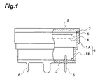
- Fig. 1 is a side view shown by partly breaking the light detection tube according to an embodiment
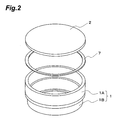
- Fig. 2 is an exploded perspective view showing a thermocompression bonding structure of a sapphire plate shown in Fig. 1.
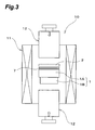
- Fig. 3 shows a schematic configuration diagram of a thermocompression bonding apparatus for obtaining the thermocompression bonding structure shown in Fig. 2.
- the light detection tube As shown in Fig. 1, the light detection tube according to the embodiment is provided with a vacuum vessel having a structure where a sapphire plate 2 as a photoreceiving face plate 2 is airtightly fixed to one end opening of a cylindrical side tube 1 forming a light entering window, and a stem plate 3 is airtightly fixed to the other end opening.
- a reflected type dynode 4 and anode 5 are accommodated in the vacuum vessel.
- the side tube 1 is integrally composed by brazing or the like a large diameter kovar metal tube 1A to which the sapphire plate 2 is fixed, and a small diameter kovar metal tube 1B to which the stem plate 3 is fixed.
- the sapphire plate 2 is attached to a light entering window of the vacuum vessel as a window material having good ultraviolet ray transmitting efficiency. Since the sapphire plate 2 having a thickness of 0.5 mm or less is easily damaged, and the sapphire plate 2 having a thickness of 1.0 mm or more is reduced in transmissivity of a ultraviolet ray, the thickness of the sapphire plate 2 is set to about 0.7 mm. Incidentally, although the transmissivity of the ultraviolet ray of 270 nm is 85% in the sapphire plate 2 having the thickness of 0.7 mm, the transmissivity of the ultraviolet ray of 270 nm is reduced to 80% in the sapphire plate 2 having the thickness of 1.0 mm.
- a photoelectric face for generating photoelectrons by the absorption of the ultraviolet ray is formed on the inner surface of the sapphire plate 2. Therefore, a single crystal sapphire plate suitable for the formation of the photoelectric face is used as the sapphire plate 2.
- the photoelectric face is composed of a semiconductor photoelectric face having an activity layer of, for example, AlGaN.
- the stem plate 3 is formed of borosilicate glass, and a plurality of stem pins 6 are airtightly penetrated in the stem plate 3. Each stem pin 6 is connected to the dynode 4 and anode 5 arranged in the kovar metal tube 1A constituting the side tube 1.
- the sapphire plate 2 is formed in a circular shape.
- the peripheral part of the inner surface is airtightly thermally crimped to the window peripheral part surrounding the light entering window of the vacuum vessel, that is, to the opening side end face of the large diameter kovar metal tube 1A constituting the side tube 1 via a circular seal ring 7 made of aluminum.
- thermocompression bonding work of the sapphire plate 2 is executed by a thermocompression bonding apparatus 10 shown in Fig. 3.
- This thermocompression bonding apparatus 10 is provided with a pair of pressurizing mechanisms 12 and 12 pressing the sapphire plate 2 and the side tube 1 via the seal ring 7, and an electric furnace 11 surrounding the pressurizing mechanisms 12 and 12.
- thermocompression bonding work of the sapphire plate 2 using the thermocompression bonding apparatus 10 first, the sapphire plate 2, the seal ring 7 and the side tube 1 are heated to 470°C from a room temperature by the electric furnace 11, and are held as they are for about 25 minutes in that state.
- the peripheral part of the sapphire plate 2 with the seal ring 7 sandwiched is then pressurized to the end face of the opening of the large diameter kovar metal tube 1A constituting the side tube 1 with pressure of about 2 kPa, and is held as they are for about 25 minutes in that state.
- the peripheral part of the sapphire plate 2 is airtightly thermally crimped to the opening side end face of the kovar metal tube 1A via the seal ring 7 made of aluminum by slowly cooling to around the room temperature to release the pressurized state.
- the sapphire plate 2 is not subjected to metallizing treatment in the light detection tube of the embodiment, a lattice defect is prevented from occurring on the sapphire plate due to diffusion of impurities on the sapphire plate 2. Therefore, even when the sapphire plate 2 is irradiated with the ultraviolet ray as a light to be measured, the generation of the phosphorescence or fluorescence from the sapphire plate 2 is prevented, and the generation of the unnecessary dark noise is prevented from the photoelectric face of the rear surface of the sapphire plate 2.
- the light detection tube according to the prevent invention is not limited to the embodiment.
- the kovar metal tube 1A in which the sapphire plate 2 as the photoreceiving face plate is thermally crimped via the seal ring 7 made of aluminum can be changed into a ceramic tube.
- the seal ring 7 is formed in a square-ring-shape, and the sapphire plate 2 is formed in a square shape.
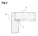
- the peripheral part of the sapphire plate 2 may be thermally crimped to the opening side end face of the kovar metal tube 1A or ceramic pipe via the seal ring 7 in a state where the peripheral part is fitted into the opening side end face by a spigot.
- the present invention can provide the light detection tube capable of preventing the situation wherein phosphorescence or fluorescence is generated from the sapphire plate in detecting the ultraviolet rays, and of reducing the dark noise.
Landscapes
- Photometry And Measurement Of Optical Pulse Characteristics (AREA)
Abstract
Description
- The present invention relates to a light detection tube in which a sapphire plate as a photoreceiving face plate is attached to a light entering window of a vacuum vessel.
- In the light detection tube in which the photoreceiving face plate is attached to the light entering window of the vacuum vessel, when the photoreceiving face plate is composed of the sapphire plate so as to detect an ultraviolet ray, the peripheral part of the photoreceiving face plate is usually brazed to a window peripheral part made of metal or ceramics, surrounding the light entering window of the vacuum vessel. In this case, so as to firmly braze and fix, the peripheral part of the photoreceiving face plate is previously subjected to metallizing treatment.
- When the photoreceiving face plate is made of quartz and the window peripheral part surrounding the light entering window of the vacuum vessel is made of kovar metal, a technique has been conventionally known, which airtightly thermally crimps the peripheral part of the photoreceiving face plate to the window peripheral part via a seal ring made of aluminum (for example, refer to a Patent Document 1). Similarly, another technique has also been known, which airtightly thermally crimps the peripheral part of the photoreceiving face plate made of glass and the window peripheral part made of metal or ceramics via the seal ring made of aluminum (for example, refer to a Patent Document 2).
Patent Document 1: Patent Publication No. 2690658
Patent Document 2: Japanese Published Examined Patent Application No. Sho-58-38903 - Herein, a demand for detecting feebler ultraviolet rays with high sensitivity has increased in recent years, and in the conventional light detection tube in which the photoreceiving face plate is composed of the sapphire plate and the peripheral part is subjected to metallizing treatment, feeble phosphorescence or fluorescence is generated from the sapphire plate in detecting the ultraviolet rays. As a result, the phosphorescence or fluorescence was found to become a dark noise in detecting feebler luminescence.
- Then, it is an object of the present invention to provide a light detection tube capable of preventing a situation wherein the phosphorescence or fluorescence is generated from the sapphire plate, and of reducing dark noise.
- The present inventors have conducted earnest investigations into the cause of the phosphorescence or fluorescence generated from the sapphire plate in detecting the ultraviolet rays. As a result, the present inventors have found that impurities are diffused on the sapphire plate by metallizing treatment and the cause of the phosphorescence or fluorescence generated is due to a lattice defect occurring on the sapphire plate by the impurities. The present invention was accomplished based on this finding.
- That is, a light detection tube according to the present invention, in which a sapphire plate, on which a photoelectric face is formed, as a photoreceiving face plate is attached to a light entering window of a vacuum vessel, wherein a peripheral part of the sapphire plate is airtightly thermally crimped to a window peripheral part made of metal or ceramics, surrounding the light entering window via a seal ring made of aluminum.
- In the light detection tube according to the present invention, since the peripheral part of the sapphire plate is airtightly thermally crimped to the window peripheral part made of metal or ceramics, surrounding the light entering window via the seal ring made of aluminum, the lattice defect is prevented from occurring on the sapphire plate due to diffusion of impurities on the sapphire plate. As a result, a situation is prevented, wherein the phosphorescence or fluorescence is generated from the sapphire plate in detecting the ultraviolet rays.
- In the light detection tube of the present invention, since the sapphire plate having a thickness of 0.5 mm or less is easily damaged and the sapphire plate having a thickness of 1.0 mm or more is reduced in transmissivity of an ultraviolet ray, it is preferable that the sapphire plate has the thickness of 0.5 to 1.0 mm, and more preferably about 0.7 mm.
- In the light detection tube according to the present invention, since the peripheral part of the sapphire plate is airtightly thermally crimped to the window peripheral part made of metal or ceramics, surrounding the light entering window via the seal ring made of aluminum, the lattice defect is prevented from occurring on the sapphire plate due to diffusion of impurities on the sapphire plate. Therefore, according to the present invention, the situation can be prevented, wherein the phosphorescence or fluorescence is generated from the sapphire plate in detecting an ultraviolet ray, and the dark noise can be reduced.
-
- Fig. 1 is a side view shown by partly breaking a light detection tube according to an embodiment;
- Fig. 2 is an exploded perspective view showing a thermocompression bonding structure of a sapphire plate shown in Fig. 1;
- Fig. 3 shows a schematic configuration diagram of a thermocompression bonding apparatus for obtaining the thermocompression bonding structure shown in Fig. 2; and
- Fig. 4 is a partial enlarged sectional view showing a modification of the thermocompression bonding structure of the sapphire plate.
- Hereinafter, an embodiment of the light detection tube according to the present invention will be described with reference to the drawings. In the referred to drawings, Fig. 1 is a side view shown by partly breaking the light detection tube according to an embodiment, and Fig. 2 is an exploded perspective view showing a thermocompression bonding structure of a sapphire plate shown in Fig. 1. Fig. 3 shows a schematic configuration diagram of a thermocompression bonding apparatus for obtaining the thermocompression bonding structure shown in Fig. 2.
- As shown in Fig. 1, the light detection tube according to the embodiment is provided with a vacuum vessel having a structure where a
sapphire plate 2 as aphotoreceiving face plate 2 is airtightly fixed to one end opening of acylindrical side tube 1 forming a light entering window, and astem plate 3 is airtightly fixed to the other end opening. Areflected type dynode 4 andanode 5 are accommodated in the vacuum vessel. - The
side tube 1 is integrally composed by brazing or the like a large diameterkovar metal tube 1A to which thesapphire plate 2 is fixed, and a small diameterkovar metal tube 1B to which thestem plate 3 is fixed. - The
sapphire plate 2 is attached to a light entering window of the vacuum vessel as a window material having good ultraviolet ray transmitting efficiency. Since thesapphire plate 2 having a thickness of 0.5 mm or less is easily damaged, and thesapphire plate 2 having a thickness of 1.0 mm or more is reduced in transmissivity of a ultraviolet ray, the thickness of thesapphire plate 2 is set to about 0.7 mm. Incidentally, although the transmissivity of the ultraviolet ray of 270 nm is 85% in thesapphire plate 2 having the thickness of 0.7 mm, the transmissivity of the ultraviolet ray of 270 nm is reduced to 80% in thesapphire plate 2 having the thickness of 1.0 mm. - A photoelectric face for generating photoelectrons by the absorption of the ultraviolet ray is formed on the inner surface of the
sapphire plate 2. Therefore, a single crystal sapphire plate suitable for the formation of the photoelectric face is used as thesapphire plate 2. The photoelectric face is composed of a semiconductor photoelectric face having an activity layer of, for example, AlGaN. - The
stem plate 3 is formed of borosilicate glass, and a plurality ofstem pins 6 are airtightly penetrated in thestem plate 3. Eachstem pin 6 is connected to thedynode 4 andanode 5 arranged in thekovar metal tube 1A constituting theside tube 1. - Herein, as shown in Fig. 2, the
sapphire plate 2 is formed in a circular shape. The peripheral part of the inner surface is airtightly thermally crimped to the window peripheral part surrounding the light entering window of the vacuum vessel, that is, to the opening side end face of the large diameterkovar metal tube 1A constituting theside tube 1 via acircular seal ring 7 made of aluminum. - The thermocompression bonding work of the
sapphire plate 2 is executed by athermocompression bonding apparatus 10 shown in Fig. 3. Thisthermocompression bonding apparatus 10 is provided with a pair of pressurizingmechanisms sapphire plate 2 and theside tube 1 via theseal ring 7, and anelectric furnace 11 surrounding thepressurizing mechanisms - In the thermocompression bonding work of the
sapphire plate 2 using thethermocompression bonding apparatus 10, first, thesapphire plate 2, theseal ring 7 and theside tube 1 are heated to 470°C from a room temperature by theelectric furnace 11, and are held as they are for about 25 minutes in that state. The peripheral part of thesapphire plate 2 with theseal ring 7 sandwiched is then pressurized to the end face of the opening of the large diameterkovar metal tube 1A constituting theside tube 1 with pressure of about 2 kPa, and is held as they are for about 25 minutes in that state. The peripheral part of thesapphire plate 2 is airtightly thermally crimped to the opening side end face of thekovar metal tube 1A via theseal ring 7 made of aluminum by slowly cooling to around the room temperature to release the pressurized state. - Herein, since the
sapphire plate 2 is not subjected to metallizing treatment in the light detection tube of the embodiment, a lattice defect is prevented from occurring on the sapphire plate due to diffusion of impurities on thesapphire plate 2. Therefore, even when thesapphire plate 2 is irradiated with the ultraviolet ray as a light to be measured, the generation of the phosphorescence or fluorescence from thesapphire plate 2 is prevented, and the generation of the unnecessary dark noise is prevented from the photoelectric face of the rear surface of thesapphire plate 2. - The light detection tube according to the prevent invention is not limited to the embodiment. For example, the
kovar metal tube 1A in which thesapphire plate 2 as the photoreceiving face plate is thermally crimped via theseal ring 7 made of aluminum can be changed into a ceramic tube. - When the
kovar metal tube 1A and the ceramic tube are formed in a square cylindrical shape, theseal ring 7 is formed in a square-ring-shape, and thesapphire plate 2 is formed in a square shape. - Furthermore, as shown in Fig. 4, the peripheral part of the
sapphire plate 2 may be thermally crimped to the opening side end face of thekovar metal tube 1A or ceramic pipe via theseal ring 7 in a state where the peripheral part is fitted into the opening side end face by a spigot. - Since the peripheral part of the sapphire plate is airtightly thermally crimped to the window peripheral part made of metal or ceramics, surrounding the light entering window via the seal ring made of aluminum in the present invention, the lattice defect is prevented from occurring on the sapphire plate due to diffusion of impurities on the sapphire plate. Therefore, the present invention can provide the light detection tube capable of preventing the situation wherein phosphorescence or fluorescence is generated from the sapphire plate in detecting the ultraviolet rays, and of reducing the dark noise.
Claims (2)
- A light detection tube in which a sapphire plate, on which a photoelectric face is formed, as a photoreceiving face plate is attached to a light entering window of a vacuum vessel,
wherein a peripheral part of the sapphire plate is airtightly thermally crimped to a window peripheral part made of metal or ceramics, surrounding the light entering window via a seal ring made of aluminum. - The light detection tube according to Claim 1, wherein the sapphire plate has a thickness of 0.5 to 1.0 mm.
Applications Claiming Priority (2)
| Application Number | Priority Date | Filing Date | Title |
|---|---|---|---|
| JP2003172504A JP4256212B2 (en) | 2003-06-17 | 2003-06-17 | Photodetector tube |
| PCT/JP2004/008358 WO2004114359A1 (en) | 2003-06-17 | 2004-06-15 | Photo-detecting tube |
Publications (3)
| Publication Number | Publication Date |
|---|---|
| EP1641021A1 true EP1641021A1 (en) | 2006-03-29 |
| EP1641021A4 EP1641021A4 (en) | 2008-05-28 |
| EP1641021B1 EP1641021B1 (en) | 2014-12-31 |
Family
ID=33534675
Family Applications (1)
| Application Number | Title | Priority Date | Filing Date |
|---|---|---|---|
| EP04745912.8A Expired - Lifetime EP1641021B1 (en) | 2003-06-17 | 2004-06-15 | Photo-detecting tube |
Country Status (4)
| Country | Link |
|---|---|
| US (1) | US20070272832A1 (en) |
| EP (1) | EP1641021B1 (en) |
| JP (1) | JP4256212B2 (en) |
| WO (1) | WO2004114359A1 (en) |
Families Citing this family (4)
| Publication number | Priority date | Publication date | Assignee | Title |
|---|---|---|---|---|
| JP2007157442A (en) * | 2005-12-02 | 2007-06-21 | Hamamatsu Photonics Kk | Photomultiplier tube |
| JP5575355B2 (en) * | 2006-10-06 | 2014-08-20 | 株式会社 資生堂 | UV protection effect evaluation device |
| US9500808B2 (en) * | 2012-05-09 | 2016-11-22 | The Boeing Company | Ruggedized photonic crystal sensor packaging |
| US10109473B1 (en) | 2018-01-26 | 2018-10-23 | Excelitas Technologies Corp. | Mechanically sealed tube for laser sustained plasma lamp and production method for same |
Family Cites Families (7)
| Publication number | Priority date | Publication date | Assignee | Title |
|---|---|---|---|---|
| US3424568A (en) * | 1965-09-09 | 1969-01-28 | Corning Glass Works | Method of sealing and resilient seal for elements having different coefficients of expansion |
| JP3466712B2 (en) * | 1994-06-28 | 2003-11-17 | 浜松ホトニクス株式会社 | Electron tube |
| US5594301A (en) * | 1994-06-30 | 1997-01-14 | Hamamatsu Photonics K.K. | Electron tube including aluminum seal ring |
| JP2000048743A (en) * | 1998-05-26 | 2000-02-18 | Futaba Corp | Planar imaging device and method of manufacturing the same |
| US6166365A (en) * | 1998-07-16 | 2000-12-26 | Schlumberger Technology Corporation | Photodetector and method for manufacturing it |
| JP2002150928A (en) * | 2000-11-15 | 2002-05-24 | Hamamatsu Photonics Kk | Semiconductor photocathode |
| JP2003014849A (en) * | 2001-06-28 | 2003-01-15 | Hamamatsu Photonics Kk | Electron tube |
-
2003
- 2003-06-17 JP JP2003172504A patent/JP4256212B2/en not_active Expired - Lifetime
-
2004
- 2004-06-15 EP EP04745912.8A patent/EP1641021B1/en not_active Expired - Lifetime
- 2004-06-15 WO PCT/JP2004/008358 patent/WO2004114359A1/en not_active Ceased
- 2004-06-15 US US10/560,921 patent/US20070272832A1/en not_active Abandoned
Also Published As
| Publication number | Publication date |
|---|---|
| US20070272832A1 (en) | 2007-11-29 |
| EP1641021A4 (en) | 2008-05-28 |
| EP1641021B1 (en) | 2014-12-31 |
| JP2005011593A (en) | 2005-01-13 |
| WO2004114359A1 (en) | 2004-12-29 |
| JP4256212B2 (en) | 2009-04-22 |
Similar Documents
| Publication | Publication Date | Title |
|---|---|---|
| CN100399585C (en) | UV sensor | |
| TWI631722B (en) | Light multiplier tube, image sensor and detection system using photomultiplier tube (PMT) or image sensor | |
| KR100492139B1 (en) | Photocathodes and electron tubes containing them | |
| EP4143868B1 (en) | Electronically addressable display incorporated into a transmission mode secondary electron image intensifier | |
| EP1641021B1 (en) | Photo-detecting tube | |
| CN110870041B (en) | Electron tube | |
| JP2001507498A (en) | Integrated photocathode | |
| US6580215B2 (en) | Photocathode | |
| KR100822139B1 (en) | Photocathode cathode and electron tube using polycrystalline diamond thin film | |
| JP2003338260A (en) | Semiconductor photocathode, method of manufacturing the same, and photodetector tube using this semiconductor photocathode | |
| JPH09213206A (en) | Transmissive photocathode, method for manufacturing the same, and photoelectric conversion tube using the same | |
| JP4611562B2 (en) | Luminescent reaction measuring device | |
| JP5000216B2 (en) | Photocathode and electron tube | |
| JPH06163968A (en) | Ultraviolet radiation detecting device and its manufacture | |
| WO2007063678A1 (en) | Photomultiplier | |
| TWI877437B (en) | Light-emitting element, light detection module, method for manufacturing light-emitting element, and scanning electron microscope | |
| JPH11102658A (en) | Light detection tube | |
| JP2003014849A (en) | Electron tube | |
| JPH10149761A (en) | Photocathode and electron tube having the same | |
| CN121954215A (en) | Vacuum solid integrated light digital solar blind ultraviolet device | |
| US20060033432A1 (en) | Photomultiplier tube with improved light collection | |
| JPH11102660A (en) | Light detection tube | |
| JP2006302843A (en) | Photoelectric surface and electron tube provided with it | |
| JPH11102659A (en) | Light detection tube | |
| Kern et al. | Expected progress based on aluminium galium nitride Focal Plan Array for near and deep Ultraviolet |
Legal Events
| Date | Code | Title | Description |
|---|---|---|---|
| PUAI | Public reference made under article 153(3) epc to a published international application that has entered the european phase |
Free format text: ORIGINAL CODE: 0009012 |
|
| 17P | Request for examination filed |
Effective date: 20060104 |
|
| AK | Designated contracting states |
Kind code of ref document: A1 Designated state(s): DE GB NL |
|
| DAX | Request for extension of the european patent (deleted) | ||
| RBV | Designated contracting states (corrected) |
Designated state(s): DE GB NL |
|
| A4 | Supplementary search report drawn up and despatched |
Effective date: 20080429 |
|
| 17Q | First examination report despatched |
Effective date: 20081008 |
|
| GRAP | Despatch of communication of intention to grant a patent |
Free format text: ORIGINAL CODE: EPIDOSNIGR1 |
|
| INTG | Intention to grant announced |
Effective date: 20140905 |
|
| GRAS | Grant fee paid |
Free format text: ORIGINAL CODE: EPIDOSNIGR3 |
|
| GRAA | (expected) grant |
Free format text: ORIGINAL CODE: 0009210 |
|
| AK | Designated contracting states |
Kind code of ref document: B1 Designated state(s): DE GB NL |
|
| REG | Reference to a national code |
Ref country code: GB Ref legal event code: FG4D |
|
| REG | Reference to a national code |
Ref country code: NL Ref legal event code: T3 |
|
| REG | Reference to a national code |
Ref country code: DE Ref legal event code: R096 Ref document number: 602004046429 Country of ref document: DE Effective date: 20150226 |
|
| REG | Reference to a national code |
Ref country code: DE Ref legal event code: R097 Ref document number: 602004046429 Country of ref document: DE |
|
| PLBE | No opposition filed within time limit |
Free format text: ORIGINAL CODE: 0009261 |
|
| STAA | Information on the status of an ep patent application or granted ep patent |
Free format text: STATUS: NO OPPOSITION FILED WITHIN TIME LIMIT |
|
| 26N | No opposition filed |
Effective date: 20151001 |
|
| P01 | Opt-out of the competence of the unified patent court (upc) registered |
Effective date: 20230509 |
|
| PGFP | Annual fee paid to national office [announced via postgrant information from national office to epo] |
Ref country code: NL Payment date: 20230515 Year of fee payment: 20 Ref country code: DE Payment date: 20230502 Year of fee payment: 20 |
|
| PGFP | Annual fee paid to national office [announced via postgrant information from national office to epo] |
Ref country code: GB Payment date: 20230427 Year of fee payment: 20 |
|
| REG | Reference to a national code |
Ref country code: DE Ref legal event code: R071 Ref document number: 602004046429 Country of ref document: DE |
|
| REG | Reference to a national code |
Ref country code: NL Ref legal event code: MK Effective date: 20240614 |
|
| PG25 | Lapsed in a contracting state [announced via postgrant information from national office to epo] |
Ref country code: GB Free format text: LAPSE BECAUSE OF EXPIRATION OF PROTECTION Effective date: 20240614 |
|
| PG25 | Lapsed in a contracting state [announced via postgrant information from national office to epo] |
Ref country code: GB Free format text: LAPSE BECAUSE OF EXPIRATION OF PROTECTION Effective date: 20240614 |