EP1640983B1 - Method and apparatus for controlling reproduction speed of an optical disk - Google Patents
Method and apparatus for controlling reproduction speed of an optical disk Download PDFInfo
- Publication number
- EP1640983B1 EP1640983B1 EP05007877A EP05007877A EP1640983B1 EP 1640983 B1 EP1640983 B1 EP 1640983B1 EP 05007877 A EP05007877 A EP 05007877A EP 05007877 A EP05007877 A EP 05007877A EP 1640983 B1 EP1640983 B1 EP 1640983B1
- Authority
- EP
- European Patent Office
- Prior art keywords
- optical disk
- read
- data
- speed
- set forth
- Prior art date
- Legal status (The legal status is an assumption and is not a legal conclusion. Google has not performed a legal analysis and makes no representation as to the accuracy of the status listed.)
- Expired - Lifetime
Links
Images



Classifications
-
- G—PHYSICS
- G11—INFORMATION STORAGE
- G11B—INFORMATION STORAGE BASED ON RELATIVE MOVEMENT BETWEEN RECORD CARRIER AND TRANSDUCER
- G11B19/00—Driving, starting, stopping record carriers not specifically of filamentary or web form, or of supports therefor; Control thereof; Control of operating function ; Driving both disc and head
- G11B19/02—Control of operating function, e.g. switching from recording to reproducing
- G11B19/04—Arrangements for preventing, inhibiting, or warning against double recording on the same blank or against other recording or reproducing malfunctions
-
- G—PHYSICS
- G11—INFORMATION STORAGE
- G11B—INFORMATION STORAGE BASED ON RELATIVE MOVEMENT BETWEEN RECORD CARRIER AND TRANSDUCER
- G11B19/00—Driving, starting, stopping record carriers not specifically of filamentary or web form, or of supports therefor; Control thereof; Control of operating function ; Driving both disc and head
- G11B19/02—Control of operating function, e.g. switching from recording to reproducing
- G11B19/06—Control of operating function, e.g. switching from recording to reproducing by counting or timing of machine operations
-
- G—PHYSICS
- G11—INFORMATION STORAGE
- G11B—INFORMATION STORAGE BASED ON RELATIVE MOVEMENT BETWEEN RECORD CARRIER AND TRANSDUCER
- G11B19/00—Driving, starting, stopping record carriers not specifically of filamentary or web form, or of supports therefor; Control thereof; Control of operating function ; Driving both disc and head
- G11B19/20—Driving; Starting; Stopping; Control thereof
- G11B19/26—Speed-changing arrangements; Reversing arrangements; Drive-transfer means therefor
-
- G—PHYSICS
- G11—INFORMATION STORAGE
- G11B—INFORMATION STORAGE BASED ON RELATIVE MOVEMENT BETWEEN RECORD CARRIER AND TRANSDUCER
- G11B19/00—Driving, starting, stopping record carriers not specifically of filamentary or web form, or of supports therefor; Control thereof; Control of operating function ; Driving both disc and head
- G11B19/20—Driving; Starting; Stopping; Control thereof
- G11B19/28—Speed controlling, regulating, or indicating
Definitions
- the invention relates to a method and apparatus for controlling reproduction speed of an optical disk.
- an optical disk reproducing apparatus For read-out of information recorded on an optical disk, such as compact disc (CD) or digital versatile disc (DVD), an optical disk reproducing apparatus irradiates a laser beam onto the optical disk through an objective lens and collects the reflected beam while rotating the optical disk at an appropriate speed using a spindle motor.
- the rotational speed of the optical disk determines the data reproduction speed, which is controlled by a servo control circuit that provides drive voltage to the spindle motor.
- Maximum-speed data reproduction requires maximum-speed rotation of the optical disk, which entails more vibration and noise generated by the rotation mechanism. If a host computer that requested data read-out from an optical disk does not take the data temporarily stored in a buffer on time, the optical disk reproducing apparatus should conduct backward track jumps, in which case the benefit of the maximum-speed rotation disappears.
- the optical disk reproducing apparatus therefore, performs data read-out not with the maximum rotational speed but with a rather lower speed with a view to decreasing noise.
- an optical disk reproducing apparatus with maximum rotational speeds approximately - 24X-52X (rotational speed expressed in terms of CLV speed) in the CAV mode rotates the optical disk with - 20X-48X speeds, - 4X lower than the maximum speed at each location, as shown in FIG. 1 .
- test program such as a Landmark test (bench mark) program
- the test program issues disk read commands to the optical disk drive for measuring data read performance.
- the optical disk drive responsive to the commands performs data read-out at a speed rather lower than the maximum speed. Because the optical disk drive with maximum CAV speeds of ⁇ 24X-52X performs data read-out with speeds of ⁇ 20X-48X, the performance index obtained by the test program does not reflect the actual maximum performance of the optical disk drive.
- the performance index obtained by the test program which is lower than the expected value, makes users doubt the performance of their disk drives, which may lead to unnecessary requests for repair service.
- Document US 2004/0141438 A1 relates to a method for controlling a play speed in an optical disc device.
- An object of the invention is to solve at least the above problems and/or disadvantages and to provide at least the advantages described hereinafter.
- a method for controlling reproduction speed of an optical disk in accordance with an embodiment of the invention that includes (a) checking whether a read command has been received and (b) examining whether the received read command is intended for performance evaluation based on the number of backward track jumps of a laser beam irradiated on the optical disk.
- a method for controlling reproduction speed of an optical disk in accordance with another embodiment of the invention that includes (a) checking whether a read command has been received sequentially more than a predefined number of times, and (b) reproducing data recorded on the optical disk with a maximum rotational speed depending on the checking result.
- a method for controlling reproduction speed of an optical disk in accordance with another embodiment of the invention includes (a) examining whether a received read command is intended for performance evaluation based on how many times the read command has been received sequentially, (b) examining whether the received read command is intended for performance evaluation based on a number of backward track jumps of a laser beam irradiated on the optical disk, and (c) reproducing data recorded on the optical disk with a maximum rotational speed if both step (a) and step (b) confirm that the received read command is intended for performance evaluation.
- an apparatus for reproducing an optical disk in accordance with an embodiment of the invention that includes a motor configured to rotate the optical disk, a reader configured to read signals recorded on the optical disk, a servo unit configured to control the reader and drive the motor, a signal processor configured to demodulate the signals read by the reader into digital data, and a controller configured to check whether a read command has been received sequentially more than a predefined number of times and reproduce data recorded on the optical disk with a maximum rotational speed by controlling the servo unit depending on the checking result.
- an apparatus for reproducing an optical disk in accordance with an embodiment of the invention that includes a motor configured to rotate the optical disk, a reader configured to read signals recorded on the optical disk, a servo unit configured to control the reader and drive the motor, a signal processor configured to demodulate the signals read by the reader into digital data, a controller configured to examine whether a received read command is intended for performance evaluation based on how many times the read command has been received sequentially, examine whether the received read command is intended for performance evaluation based on a number of backward track jumps of the reader, and reproduce data recorded on the optical disk with a maximum rotational speed by controlling the servo unit if both said examinations confirm that the received read command is intended for performance evaluation.
- FIG. 1 is a graph illustrating maximum reproduction speed and actual reproduction speed of an optical disk in a related art optical disk reproducing apparatus
- FIG. 2 is a block diagram of an optical disk reproducing apparatus in accordance with an embodiment of the invention.
- FIG. 3 is a flowchart of a method of controlling reproduction speed of an optical disk in accordance with an embodiment of the invention
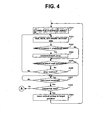
- FIG. 4 is a detailed flowchart of a maximum speed reproduction mode in the method of FIG. 3 ;
- FIG. 5 illustrates an example showing the change of reproduction speed in accordance with embodiments of the invention.
- FIG. 2 is a block diagram of an optical disk reproducing apparatus in accordance with an embodiment of the invention.
- the optical disk reproducing apparatus of FIG. 2 includes an optical pickup 12 for reproducing recorded signals from an optical disk 10, an RF unit 14 for generating a binary signal conveying recorded data and focus/tracking error signals from the output of the optical pickup 12, a DSP 15 for retrieving digital data from the binary signal, a memory 16 for temporarily storing the retrieved digital data, a buffer 17 for buffering data to be transferred to an external host, an interface unit 18 for exchanging data and commands with external devices, a servo control unit 20 for controlling the optical pickup 12, a spindle motor M for rotating the optical disk 10, and a microprocessor 26 for supervising the overall operation of the apparatus.
- an optical pickup 12 for reproducing recorded signals from an optical disk 10
- an RF unit 14 for generating a binary signal conveying recorded data and focus/tracking error signals from the output of the optical pickup 12
- a DSP 15 for retrieving digital data from the binary signal
- FIGS. 3 and 4 are flowcharts of a method of controlling reproduction speed of an optical disk in accordance with an embodiment of the invention.
- step S10 the microprocessor 26 initializes 'seq_read_cnt', which is a variable for storing the number of received sequential read commands, and 'backjump_cnt, which is a variable for storing the number of backward track jumps, to 0 , in step S12.
- the microprocessor 26 then waits for a command from an external host after performing initialization for servo control.
- the microprocessor 26 After receiving a command for reading a particular area of the optical disk 10 from an external host through the interface unit 18, the microprocessor 26 checks whether the command is for a sequential read operation, in step S14. The type of read command can be identified by the code thereof. If the received command is for other actions, such as random read, the microprocessor 26 performs the requested operation, in step S15. If the received command is a command for sequential read, the microprocessor 26 increments the variable 'seq_read_cnt', in step S16, and moves the optical pickup 12 to the area specified by the command through the servo control unit 20, in step S18.
- the rotational speed of the optical disk 10 is not set to the maximum possible speed at the targeted area but a rather lower speed (for example, a speed - 4X lower than the maximum possible speed).
- the signals read by the optical pickup 12 are converted into a binary signal by the RF unit 14 and then demodulated into digital data by the DSP 15.
- the retrieved digital data is stored sequentially in the memory in order of demodulation, in step S20.
- the data stored in the memory 16 is moved to the buffer 17 by the microprocessor 26 and the data in the buffer 17 is transferred to the external host PC through the interface unit 18.
- the microprocessor 26 loads the buffer 17 with the digital data stored in the memory 16.
- the microprocessor 26 measures the elapsed time (RT) since the data read-out initiated by the first sequential read command using an internal timer.
- the microprocessor 26 While executing the aforementioned steps, the microprocessor 26 checks whether the size of data stored in the memory 16 exceeds a predefined limit (for example, ⁇ 80 % of the memory size), in step S22. If the predefined limit is exceeded, the microprocessor 26 instructs the servo control unit 20 to perform a backward jump of the optical pickup 12, in step S24, and increments the variable 'backjump_cnt', in step S26.
- a predefined limit for example, ⁇ 80 % of the memory size
- the microprocessor 26 checks whether the sequential read of the data block requested by the read command has been completed, in step S34. If the requested sequential read operation has not been completed and no request to stop the data read operation has been received, in step S36, the microprocessor 26 repeats the aforementioned steps from step S20 until the requested sequential read operation is completed or a request to stop the data read operation is received.
- a predefined limit for example, - 5 seconds
- step S34 the microprocessor 26 waits for a next command. If a next command is received and the command is not for a sequential read operation, the microprocessor performs the requested operation, in step S15, and initializes the variables 'seq_read_cnt' and 'backjump_cnt', in step S12. If the next command is for a sequential read operation, the microprocessor 26 leaves the variables 'seq_read_cnt' and 'backjump_cnt' unchanged and repeats the aforementioned steps from step S16.
- step S27 the microprocessor 26 reads the content of the variable 'seq_read_cnt', in step S28. If the value stored therein is less than a predefined number (N), the microprocessor 26 continues the current sequential read operation; otherwise, the microprocessor 26 guesses that the repeated sequential read command is intended for performance evaluation and reads the content of the variable 'backjump_cnt', in step S30. If the value stored therein is less than a predefined number (M), the microprocessor 26 concludes the repeated sequential read command to be intended for performance evaluation; otherwise, the microprocessor 26 continues the current read operation.
- N a predefined number
- M the microprocessor 26 concludes the repeated sequential read command to be intended for performance evaluation; otherwise, the microprocessor 26 continues the current read operation.
- the sequential read command is probably intended for performance evaluation. Moreover, if the number of backward track jumps conducted during the sequential read operation is less than the predefined number M, it is almost certain that the read command is intended for performance evaluation because the data read from the optical disk is transferred to the external host through the buffer 17 sufficiently fast at the current rotational speed. Because read operations for evaluating performance simply repeat overwriting data blocks that were read sequentially from the optical disk on a same storing space without moving the read data blocks to another storage medium, interpreting or decoding of the read data blocks, the external host can focus only on the read operations and therefore the read throughput is usually very high.
- the read operations intended for performance evaluation do not cause backward track jumps. In reality, however, backward jumps are sometimes required due to disk read errors resulting from disk defects. In the embodiments of the invention, therefore, the read operations are considered to be intended for performance evaluation if the number of backward track jumps conducted during the predefined period Tref is less than the predefined number M. If the number of sequential read commands received during the predefined period Tref exceeds N and the number of backward track jumps conducted during Tref is less than the predefined number M, the microprocessor 26 regards the situation as a performance evaluation operation and executes the maximum-speed data reproduction routine, in step S32.
- FIG. 4 is a detailed flowchart of the maximum-speed reproduction mode in the method of FIG. 3 .
- the microprocessor 26 controls the servo control unit 20 to rotate the optical disk 10 with a maximum possible speed at the current position.
- the rotational speed is increased to ⁇ 36X (vj in FIG. 5 ).
- the microprocessor 26 While reproducing the optical disk 10 with the maximum rotational speed, the microprocessor 26 does not examine the values of the variables (seq_read_cnt and backjump_cnt) and conducts backward track jumps only if needed, in steps S323 and S324. If a command received during the maximum-speed reproduction operation is also for sequential read, in step S328, the microprocessor 26 moves the optical pickup 12 to the target position, in step S329, and continues the maximum-speed reproduction operation at the position, in step S321; otherwise, the microprocessor 26 performs the requested operation, in step S15, and exits the maximum-speed reproduction routine. The microprocessor 26 then rotates the optical disk with a speed lower than the maximum rotational speed, in step S18, and determines whether to enter the maximum-speed reproduction mode as described before.
- the microprocessor 26 rotates the optical disk with a speed lower than the maximum rotational speed, in step S18, and determines whether to enter the maximum-speed reproduction mode as described before.
- the method and apparatus for controlling reproduction speed of an optical disk according to embodiments of the invention provide at least the following advantages.
- the method and apparatus for controlling reproduction speed of an optical disk according to embodiments of the invention are capable of coping with performance evaluation by adjusting the rotational speed of the optical disk. Further, the method and apparatus for controlling reproduction speed of an optical disk according to embodiments of the invention provide designed read performance when an external host executes a performance test.
Landscapes
- Optical Recording Or Reproduction (AREA)
Description
- The invention relates to a method and apparatus for controlling reproduction speed of an optical disk.
- For read-out of information recorded on an optical disk, such as compact disc (CD) or digital versatile disc (DVD), an optical disk reproducing apparatus irradiates a laser beam onto the optical disk through an objective lens and collects the reflected beam while rotating the optical disk at an appropriate speed using a spindle motor. The rotational speed of the optical disk determines the data reproduction speed, which is controlled by a servo control circuit that provides drive voltage to the spindle motor.
- With the advancement of servo technology, the access speed of an optical disk reproducing apparatus has improved rapidly. As a result, data recorded on an optical disk can be retrieved more rapidly than the normal 1X speed.
- Maximum-speed data reproduction requires maximum-speed rotation of the optical disk, which entails more vibration and noise generated by the rotation mechanism. If a host computer that requested data read-out from an optical disk does not take the data temporarily stored in a buffer on time, the optical disk reproducing apparatus should conduct backward track jumps, in which case the benefit of the maximum-speed rotation disappears.
- The optical disk reproducing apparatus, therefore, performs data read-out not with the maximum rotational speed but with a rather lower speed with a view to decreasing noise. For example, an optical disk reproducing apparatus with maximum rotational speeds approximately - 24X-52X (rotational speed expressed in terms of CLV speed) in the CAV mode rotates the optical disk with - 20X-48X speeds, - 4X lower than the maximum speed at each location, as shown in
FIG. 1 . - Users sometimes execute a test program, such as a Landmark test (bench mark) program, to measure the performance of their optical disk drives installed in their PCs. When executed, the test program issues disk read commands to the optical disk drive for measuring data read performance. The optical disk drive responsive to the commands performs data read-out at a speed rather lower than the maximum speed. Because the optical disk drive with maximum CAV speeds of ~ 24X-52X performs data read-out with speeds of ~ 20X-48X, the performance index obtained by the test program does not reflect the actual maximum performance of the optical disk drive.
- The performance index obtained by the test program, which is lower than the expected value, makes users doubt the performance of their disk drives, which may lead to unnecessary requests for repair service.
- Document
US 2004/0141438 A1 relates to a method for controlling a play speed in an optical disc device. - An object of the invention is to solve at least the above problems and/or disadvantages and to provide at least the advantages described hereinafter.
- The object of the invention is achieved by the features of the appended claims.
- To achieve at least the above objects, in whole or in part, and in accordance with the purposes of the invention, as embodied and broadly described herein, there is provided a method for controlling reproduction speed of an optical disk in accordance with an embodiment of the invention that includes (a) checking whether a read command has been received and (b) examining whether the received read command is intended for performance evaluation based on the number of backward track jumps of a laser beam irradiated on the optical disk.
- To further achieve at least the above objects, in whole or in part, and in accordance with the purposes of the invention, as embodied and broadly described herein, there is provided a method for controlling reproduction speed of an optical disk in accordance with another embodiment of the invention that includes (a) checking whether a read command has been received sequentially more than a predefined number of times, and (b) reproducing data recorded on the optical disk with a maximum rotational speed depending on the checking result.
- To further achieve at least the above objects, in whole or in part, and in accordance with the purposes of the invention, as embodied and broadly described herein, a method for controlling reproduction speed of an optical disk in accordance with another embodiment of the invention is provided that includes (a) examining whether a received read command is intended for performance evaluation based on how many times the read command has been received sequentially, (b) examining whether the received read command is intended for performance evaluation based on a number of backward track jumps of a laser beam irradiated on the optical disk, and (c) reproducing data recorded on the optical disk with a maximum rotational speed if both step (a) and step (b) confirm that the received read command is intended for performance evaluation.
- To further achieve at least the above objects, in whole or in part, and in accordance with the purposes of the invention, as embodied and broadly described herein, there is provided an apparatus for reproducing an optical disk in accordance with an embodiment of the invention that includes a motor configured to rotate the optical disk, a reader configured to read signals recorded on the optical disk, a servo unit configured to control the reader and drive the motor, a signal processor configured to demodulate the signals read by the reader into digital data, and a controller configured to check whether a read command has been received sequentially more than a predefined number of times and reproduce data recorded on the optical disk with a maximum rotational speed by controlling the servo unit depending on the checking result.
- To further achieve at least the above objects, in whole or in part, and in accordance with the purposes of the invention, as embodied and broadly described herein, there is provided an apparatus for reproducing an optical disk in accordance with an embodiment of the invention that includes a motor configured to rotate the optical disk, a reader configured to read signals recorded on the optical disk, a servo unit configured to control the reader and drive the motor, a signal processor configured to demodulate the signals read by the reader into digital data, a controller configured to examine whether a received read command is intended for performance evaluation based on how many times the read command has been received sequentially, examine whether the received read command is intended for performance evaluation based on a number of backward track jumps of the reader, and reproduce data recorded on the optical disk with a maximum rotational speed by controlling the servo unit if both said examinations confirm that the received read command is intended for performance evaluation.
- Additional advantages, objects, and features of the invention will be set forth in part in the description which follows and in part will become apparent to those having ordinary skill in the art upon examination of the following or may be learned from practice of the invention. The objects and advantages of the invention may be realized and attained as particularly pointed out in the appended claims.
- The invention will be described in detail with reference to the following drawings in which like reference numerals refer to like elements wherein:
-
FIG. 1 is a graph illustrating maximum reproduction speed and actual reproduction speed of an optical disk in a related art optical disk reproducing apparatus; -
FIG. 2 is a block diagram of an optical disk reproducing apparatus in accordance with an embodiment of the invention; -
FIG. 3 is a flowchart of a method of controlling reproduction speed of an optical disk in accordance with an embodiment of the invention; -
FIG. 4 is a detailed flowchart of a maximum speed reproduction mode in the method ofFIG. 3 ; and -
FIG. 5 illustrates an example showing the change of reproduction speed in accordance with embodiments of the invention. - Now, a method and apparatus for controlling reproduction speed of an optical disk in accordance with embodiments of the invention will now be described in detail with reference to the drawings, in which like reference numerals have been used to designate like elements.
-
FIG. 2 is a block diagram of an optical disk reproducing apparatus in accordance with an embodiment of the invention. The optical disk reproducing apparatus ofFIG. 2 includes anoptical pickup 12 for reproducing recorded signals from anoptical disk 10, anRF unit 14 for generating a binary signal conveying recorded data and focus/tracking error signals from the output of theoptical pickup 12, aDSP 15 for retrieving digital data from the binary signal, amemory 16 for temporarily storing the retrieved digital data, abuffer 17 for buffering data to be transferred to an external host, aninterface unit 18 for exchanging data and commands with external devices, aservo control unit 20 for controlling theoptical pickup 12, a spindle motor M for rotating theoptical disk 10, and amicroprocessor 26 for supervising the overall operation of the apparatus. -
FIGS. 3 and4 are flowcharts of a method of controlling reproduction speed of an optical disk in accordance with an embodiment of the invention. - If the
optical disk 10 is loaded, in step S10, themicroprocessor 26 initializes 'seq_read_cnt', which is a variable for storing the number of received sequential read commands, and 'backjump_cnt, which is a variable for storing the number of backward track jumps, to 0 , in step S12. Themicroprocessor 26 then waits for a command from an external host after performing initialization for servo control. - After receiving a command for reading a particular area of the
optical disk 10 from an external host through theinterface unit 18, themicroprocessor 26 checks whether the command is for a sequential read operation, in step S14. The type of read command can be identified by the code thereof. If the received command is for other actions, such as random read, themicroprocessor 26 performs the requested operation, in step S15. If the received command is a command for sequential read, themicroprocessor 26 increments the variable 'seq_read_cnt', in step S16, and moves theoptical pickup 12 to the area specified by the command through theservo control unit 20, in step S18. The rotational speed of theoptical disk 10 is not set to the maximum possible speed at the targeted area but a rather lower speed (for example, a speed - 4X lower than the maximum possible speed). - The signals read by the
optical pickup 12 are converted into a binary signal by theRF unit 14 and then demodulated into digital data by theDSP 15. The retrieved digital data is stored sequentially in the memory in order of demodulation, in step S20. - The data stored in the
memory 16 is moved to thebuffer 17 by themicroprocessor 26 and the data in thebuffer 17 is transferred to the external host PC through theinterface unit 18. Each time thebuffer 17 becomes empty, themicroprocessor 26 loads thebuffer 17 with the digital data stored in thememory 16. Themicroprocessor 26 measures the elapsed time (RT) since the data read-out initiated by the first sequential read command using an internal timer. - While executing the aforementioned steps, the
microprocessor 26 checks whether the size of data stored in thememory 16 exceeds a predefined limit (for example, ~ 80 % of the memory size), in step S22. If the predefined limit is exceeded, themicroprocessor 26 instructs theservo control unit 20 to perform a backward jump of theoptical pickup 12, in step S24, and increments the variable 'backjump_cnt', in step S26. - If the elapsed time (RT) measured by the
microprocessor 26 is within a predefined limit (for example, - 5 seconds), themicroprocessor 26 checks whether the sequential read of the data block requested by the read command has been completed, in step S34. If the requested sequential read operation has not been completed and no request to stop the data read operation has been received, in step S36, themicroprocessor 26 repeats the aforementioned steps from step S20 until the requested sequential read operation is completed or a request to stop the data read operation is received. - If the sequential read of the requested data block has been completed, in step S34, the
microprocessor 26 waits for a next command. If a next command is received and the command is not for a sequential read operation, the microprocessor performs the requested operation, in step S15, and initializes the variables 'seq_read_cnt' and 'backjump_cnt', in step S12. If the next command is for a sequential read operation, themicroprocessor 26 leaves the variables 'seq_read_cnt' and 'backjump_cnt' unchanged and repeats the aforementioned steps from step S16. - If the sequential read command is repeated several times and the elapsed time (RT) since the initial sequential read command exceeds a predefined duration (Tref), in step S27, the
microprocessor 26 reads the content of the variable 'seq_read_cnt', in step S28. If the value stored therein is less than a predefined number (N), themicroprocessor 26 continues the current sequential read operation; otherwise, themicroprocessor 26 guesses that the repeated sequential read command is intended for performance evaluation and reads the content of the variable 'backjump_cnt', in step S30. If the value stored therein is less than a predefined number (M), themicroprocessor 26 concludes the repeated sequential read command to be intended for performance evaluation; otherwise, themicroprocessor 26 continues the current read operation. - If the sequential read operation has been continued during the predefined period Tref, the sequential read command is probably intended for performance evaluation. Moreover, if the number of backward track jumps conducted during the sequential read operation is less than the predefined number M, it is almost certain that the read command is intended for performance evaluation because the data read from the optical disk is transferred to the external host through the
buffer 17 sufficiently fast at the current rotational speed. Because read operations for evaluating performance simply repeat overwriting data blocks that were read sequentially from the optical disk on a same storing space without moving the read data blocks to another storage medium, interpreting or decoding of the read data blocks, the external host can focus only on the read operations and therefore the read throughput is usually very high. - Theoretically, read operations intended for performance evaluation do not cause backward track jumps. In reality, however, backward jumps are sometimes required due to disk read errors resulting from disk defects. In the embodiments of the invention, therefore, the read operations are considered to be intended for performance evaluation if the number of backward track jumps conducted during the predefined period Tref is less than the predefined number M. If the number of sequential read commands received during the predefined period Tref exceeds N and the number of backward track jumps conducted during Tref is less than the predefined number M, the
microprocessor 26 regards the situation as a performance evaluation operation and executes the maximum-speed data reproduction routine, in step S32. -
FIG. 4 is a detailed flowchart of the maximum-speed reproduction mode in the method ofFIG. 3 . Once the maximum-speed reproduction mode starts, themicroprocessor 26 controls theservo control unit 20 to rotate theoptical disk 10 with a maximum possible speed at the current position. In the example shown inFIG. 5 , if theoptical disk 10 has been rotated at ~ 32X speed, the rotational speed is increased to ~ 36X (vj inFIG. 5 ). - While reproducing the
optical disk 10 with the maximum rotational speed, themicroprocessor 26 does not examine the values of the variables (seq_read_cnt and backjump_cnt) and conducts backward track jumps only if needed, in steps S323 and S324. If a command received during the maximum-speed reproduction operation is also for sequential read, in step S328, themicroprocessor 26 moves theoptical pickup 12 to the target position, in step S329, and continues the maximum-speed reproduction operation at the position, in step S321; otherwise, themicroprocessor 26 performs the requested operation, in step S15, and exits the maximum-speed reproduction routine. Themicroprocessor 26 then rotates the optical disk with a speed lower than the maximum rotational speed, in step S18, and determines whether to enter the maximum-speed reproduction mode as described before. - The method and apparatus for controlling reproduction speed of an optical disk according to embodiments of the invention provide at least the following advantages.
- The method and apparatus for controlling reproduction speed of an optical disk according to embodiments of the invention are capable of coping with performance evaluation by adjusting the rotational speed of the optical disk. Further, the method and apparatus for controlling reproduction speed of an optical disk according to embodiments of the invention provide designed read performance when an external host executes a performance test.
- The foregoing embodiments and advantages are merely exemplary and are not to be construed as limiting the invention. The present teaching can be readily applied to other types of apparatuses. The description of the invention is intended to be illustrative, and not to limit the scope of the claims. Many alternatives, modifications, and variations will be apparent to those skilled in the art. In the claims, means-plus-function clauses are intended to cover the structures described herein as performing the recited function and not only structural equivalents but also equivalent structures.
Claims (7)
- A method for controlling reproduction speed of an optical disk, comprising:(a) examining whether an elapsed time since an initial sequential read command (Tref) exceeds a predefined duration;(b) examining whether the received sequential read command is intended for performance evaluation based on how many times (N) the read command has been received sequentially;(c) examining whether the received sequential read command is intended for performance evaluation based on a number of backward track jumps (M) of a laser beam irradiated on the optical disk, and(d) performing maximum speed reproduction if all of the above conditions are fulfilled.
- The method as set forth in claim 1, wherein step (a) is executed while reproducing data recorded on the optical disk at a speed less than the maximum rotational speed.
- The method as set forth in claim 1 wherein step (a) additionally checks whether a size of data that remains in a memory exceeds a predefined reference size.
- The method as set forth in claim 3, wherein the memory temporarily storing data read from the optical disk before the data is transferred to an external host.
- An apparatus for reproducing an optical disk (10), comprising:a motor (M) configured to rotate the optical disk,a reader (12,14) configured to read signals recorded on the optical disk,a servo unit (20) configured to control the reader and drive the motor;a signal processor (15) configured to demodulate the signals read by the reader into digital data; anda controller (26) configured to control the servo unit according to a method as set forth in any of claims 1 to 4.
- The apparatus as set forth in claim 5, further comprising;an interface unit (18) configured to exchange data with an external host.
- The apparatus as set forth in claim 6, further comprising;a storage device (17) configured to temporarily store the digital data that will be transferred to the external host through the interface unit.
Applications Claiming Priority (1)
| Application Number | Priority Date | Filing Date | Title |
|---|---|---|---|
| KR1020040076278A KR101114943B1 (en) | 2004-09-23 | 2004-09-23 | Method and apparatus for controlling reproducing speed of a disk recording medium |
Publications (3)
| Publication Number | Publication Date |
|---|---|
| EP1640983A2 EP1640983A2 (en) | 2006-03-29 |
| EP1640983A3 EP1640983A3 (en) | 2007-09-05 |
| EP1640983B1 true EP1640983B1 (en) | 2009-10-21 |
Family
ID=36145147
Family Applications (1)
| Application Number | Title | Priority Date | Filing Date |
|---|---|---|---|
| EP05007877A Expired - Lifetime EP1640983B1 (en) | 2004-09-23 | 2005-04-11 | Method and apparatus for controlling reproduction speed of an optical disk |
Country Status (6)
| Country | Link |
|---|---|
| US (1) | US7800995B2 (en) |
| EP (1) | EP1640983B1 (en) |
| KR (1) | KR101114943B1 (en) |
| CN (1) | CN1753088B (en) |
| DE (1) | DE602005017231D1 (en) |
| TW (1) | TWI361428B (en) |
Families Citing this family (1)
| Publication number | Priority date | Publication date | Assignee | Title |
|---|---|---|---|---|
| US10031850B2 (en) * | 2011-06-07 | 2018-07-24 | Sandisk Technologies Llc | System and method to buffer data |
Family Cites Families (17)
| Publication number | Priority date | Publication date | Assignee | Title |
|---|---|---|---|---|
| US5592446A (en) * | 1993-06-14 | 1997-01-07 | Sony Corporation | Dual mode recording and reproducing apparatus having two recording regions using differing reproduction principles |
| JP3430911B2 (en) * | 1998-03-24 | 2003-07-28 | ティアック株式会社 | Optical disk drive |
| JPH11296990A (en) * | 1998-04-07 | 1999-10-29 | Sanyo Electric Co Ltd | Disk reproducing device |
| KR20010004773A (en) * | 1999-06-29 | 2001-01-15 | 구자홍 | Method for controling velocity of reproducing speed on disc player |
| JP4538907B2 (en) * | 1999-06-29 | 2010-09-08 | ソニー株式会社 | Recording apparatus and reproducing apparatus |
| KR100558986B1 (en) * | 1999-09-30 | 2006-03-10 | 엘지전자 주식회사 | Optical Disc Playback Speed Control Device and Control Method According to Battery Charge |
| JP3544504B2 (en) * | 2000-02-16 | 2004-07-21 | 松下電器産業株式会社 | Data reproduction device, data reproduction method, and recording medium |
| US6836454B2 (en) * | 2000-03-08 | 2004-12-28 | Hitachi, Ltd. | Method and apparatus for reading and writing information onto and from information recording disks |
| JP3860394B2 (en) * | 2000-06-20 | 2006-12-20 | 株式会社リコー | Information reproducing method and information reproducing apparatus |
| TW519619B (en) * | 2001-05-23 | 2003-02-01 | Lite On It Corp | Method for determining rotating speed of compact disc player by system detection |
| EP1262975A2 (en) * | 2001-05-31 | 2002-12-04 | Matsushita Electric Industrial Co., Ltd. | Disc drive device with speed control means |
| US7403459B2 (en) * | 2002-01-22 | 2008-07-22 | Lite-On It Corp. | Rotational speed control method for a disk player |
| JP4273693B2 (en) * | 2002-02-12 | 2009-06-03 | ティアック株式会社 | Information recording and / or reproducing method and information recording and / or reproducing apparatus |
| US7254525B2 (en) * | 2002-10-17 | 2007-08-07 | Hitachi Global Storage Technologies Netherlands B.V. | Method and apparatus for automated analysis of hard disk drive performance |
| KR100499584B1 (en) * | 2003-01-03 | 2005-07-07 | 주식회사 히타치엘지 데이터 스토리지 코리아 | Method for controlling data read speed for medium |
| KR100532457B1 (en) * | 2003-08-06 | 2005-11-30 | 삼성전자주식회사 | Apparatus and method for handling reading failure of storage medium having moving image and for reproducing the storage medium |
| DE602004026745D1 (en) * | 2003-09-16 | 2010-06-02 | Koninkl Philips Electronics Nv | METHOD AND DEVICE FOR PLAYING OPTICAL DATA CARRIER AND METHOD FOR DETERMINING THE TRACKING QUALITY |
-
2004
- 2004-09-23 KR KR1020040076278A patent/KR101114943B1/en not_active Expired - Fee Related
-
2005
- 2005-04-11 DE DE602005017231T patent/DE602005017231D1/en not_active Expired - Lifetime
- 2005-04-11 EP EP05007877A patent/EP1640983B1/en not_active Expired - Lifetime
- 2005-04-13 TW TW094111722A patent/TWI361428B/en not_active IP Right Cessation
- 2005-05-18 US US11/131,216 patent/US7800995B2/en not_active Expired - Fee Related
- 2005-06-06 CN CN2005100749764A patent/CN1753088B/en not_active Expired - Fee Related
Also Published As
| Publication number | Publication date |
|---|---|
| EP1640983A2 (en) | 2006-03-29 |
| TW200611260A (en) | 2006-04-01 |
| US20060077832A1 (en) | 2006-04-13 |
| EP1640983A3 (en) | 2007-09-05 |
| US7800995B2 (en) | 2010-09-21 |
| TWI361428B (en) | 2012-04-01 |
| CN1753088B (en) | 2010-10-13 |
| DE602005017231D1 (en) | 2009-12-03 |
| CN1753088A (en) | 2006-03-29 |
| KR20060027497A (en) | 2006-03-28 |
| KR101114943B1 (en) | 2012-03-06 |
Similar Documents
| Publication | Publication Date | Title |
|---|---|---|
| JPH04245026A (en) | Device and method of controlling disk-recorder | |
| JPH08329597A (en) | Disc inspection method | |
| US7130255B2 (en) | Method of CD/DVD vibration detection by monitoring motor conditions | |
| US6697310B1 (en) | Storage apparatus and calibrating method | |
| EP1640983A2 (en) | Method and apparatus for controlling reproduction speed of an optical disk | |
| US6836454B2 (en) | Method and apparatus for reading and writing information onto and from information recording disks | |
| US6977873B2 (en) | System and method to adjust the level of re-calibration effort based on disc drive performance | |
| KR100457140B1 (en) | Method and system for controlling disk servo | |
| US7057983B2 (en) | System and method for controlling tracking and seeking in an optical disc drive | |
| KR100524932B1 (en) | Speed control method of disc drive and apparatus therefor, and recording media which a program therefor is recorded | |
| US8520480B2 (en) | Optical disc apparatus, method of controlling the same, and information storage medium | |
| CN100424762C (en) | Power regulating method for optical disc accessed by reading head and relevant optical disc information reproducing device | |
| KR100498479B1 (en) | Method and apparatus for controlling spindle speed for enhance readability of disc | |
| CN100527235C (en) | Optical disk recording/reproducing apparatus and test writing method thereof | |
| JP2004110962A (en) | Information recording / reproducing device | |
| US20080002539A1 (en) | Optical disk apparatus and an alternation process method for the same | |
| JP4202874B2 (en) | Optical recording apparatus and method | |
| JPH0883430A (en) | Information recording / reproducing device | |
| US20070121441A1 (en) | Optical disk recording/reproducing apparatus and seek control method thereof | |
| JP2000003548A (en) | Disk unit | |
| KR20060098866A (en) | How to set the optimal recording speed for high speed digital video discs | |
| JP2003006882A (en) | Optical disk drive | |
| KR20120057956A (en) | Apparatus and method for reducing current consumption in optical disc drive | |
| JP2007102839A (en) | Information recording / reproducing device | |
| JPH09282782A (en) | Optical disc device and optical disc startup method |
Legal Events
| Date | Code | Title | Description |
|---|---|---|---|
| PUAI | Public reference made under article 153(3) epc to a published international application that has entered the european phase |
Free format text: ORIGINAL CODE: 0009012 |
|
| AK | Designated contracting states |
Kind code of ref document: A2 Designated state(s): AT BE BG CH CY CZ DE DK EE ES FI FR GB GR HU IE IS IT LI LT LU MC NL PL PT RO SE SI SK TR |
|
| AX | Request for extension of the european patent |
Extension state: AL BA HR LV MK YU |
|
| PUAL | Search report despatched |
Free format text: ORIGINAL CODE: 0009013 |
|
| AK | Designated contracting states |
Kind code of ref document: A3 Designated state(s): AT BE BG CH CY CZ DE DK EE ES FI FR GB GR HU IE IS IT LI LT LU MC NL PL PT RO SE SI SK TR |
|
| AX | Request for extension of the european patent |
Extension state: AL BA HR LV MK YU |
|
| RIC1 | Information provided on ipc code assigned before grant |
Ipc: G11B 19/06 20060101ALI20070730BHEP Ipc: G11B 19/28 20060101ALI20070730BHEP Ipc: G11B 19/26 20060101AFI20051220BHEP Ipc: G11B 19/04 20060101ALI20070730BHEP |
|
| 17P | Request for examination filed |
Effective date: 20080225 |
|
| AKX | Designation fees paid |
Designated state(s): DE FR GB NL |
|
| 17Q | First examination report despatched |
Effective date: 20080618 |
|
| GRAP | Despatch of communication of intention to grant a patent |
Free format text: ORIGINAL CODE: EPIDOSNIGR1 |
|
| GRAS | Grant fee paid |
Free format text: ORIGINAL CODE: EPIDOSNIGR3 |
|
| GRAA | (expected) grant |
Free format text: ORIGINAL CODE: 0009210 |
|
| AK | Designated contracting states |
Kind code of ref document: B1 Designated state(s): DE FR GB NL |
|
| REG | Reference to a national code |
Ref country code: GB Ref legal event code: FG4D |
|
| REF | Corresponds to: |
Ref document number: 602005017231 Country of ref document: DE Date of ref document: 20091203 Kind code of ref document: P |
|
| PLBE | No opposition filed within time limit |
Free format text: ORIGINAL CODE: 0009261 |
|
| STAA | Information on the status of an ep patent application or granted ep patent |
Free format text: STATUS: NO OPPOSITION FILED WITHIN TIME LIMIT |
|
| 26N | No opposition filed |
Effective date: 20100722 |
|
| PGFP | Annual fee paid to national office [announced via postgrant information from national office to epo] |
Ref country code: GB Payment date: 20120330 Year of fee payment: 8 |
|
| PGFP | Annual fee paid to national office [announced via postgrant information from national office to epo] |
Ref country code: NL Payment date: 20120403 Year of fee payment: 8 Ref country code: DE Payment date: 20120329 Year of fee payment: 8 |
|
| PGFP | Annual fee paid to national office [announced via postgrant information from national office to epo] |
Ref country code: FR Payment date: 20120419 Year of fee payment: 8 |
|
| REG | Reference to a national code |
Ref country code: NL Ref legal event code: V1 Effective date: 20131101 |
|
| GBPC | Gb: european patent ceased through non-payment of renewal fee |
Effective date: 20130411 |
|
| PG25 | Lapsed in a contracting state [announced via postgrant information from national office to epo] |
Ref country code: DE Free format text: LAPSE BECAUSE OF NON-PAYMENT OF DUE FEES Effective date: 20131101 Ref country code: GB Free format text: LAPSE BECAUSE OF NON-PAYMENT OF DUE FEES Effective date: 20130411 |
|
| REG | Reference to a national code |
Ref country code: FR Ref legal event code: ST Effective date: 20131231 |
|
| REG | Reference to a national code |
Ref country code: DE Ref legal event code: R119 Ref document number: 602005017231 Country of ref document: DE Effective date: 20131101 |
|
| PG25 | Lapsed in a contracting state [announced via postgrant information from national office to epo] |
Ref country code: NL Free format text: LAPSE BECAUSE OF NON-PAYMENT OF DUE FEES Effective date: 20131101 Ref country code: FR Free format text: LAPSE BECAUSE OF NON-PAYMENT OF DUE FEES Effective date: 20130430 |