EP1640733A1 - Method and device for digitally measuring the phase of a signal - Google Patents
Method and device for digitally measuring the phase of a signal Download PDFInfo
- Publication number
- EP1640733A1 EP1640733A1 EP04292278A EP04292278A EP1640733A1 EP 1640733 A1 EP1640733 A1 EP 1640733A1 EP 04292278 A EP04292278 A EP 04292278A EP 04292278 A EP04292278 A EP 04292278A EP 1640733 A1 EP1640733 A1 EP 1640733A1
- Authority
- EP
- European Patent Office
- Prior art keywords
- frequency
- phase
- sampling
- signal
- counter
- Prior art date
- Legal status (The legal status is an assumption and is not a legal conclusion. Google has not performed a legal analysis and makes no representation as to the accuracy of the status listed.)
- Granted
Links
- 238000000034 method Methods 0.000 title claims abstract description 49
- 238000005070 sampling Methods 0.000 claims abstract description 81
- 230000005540 biological transmission Effects 0.000 claims abstract description 18
- 230000001360 synchronised effect Effects 0.000 claims description 32
- 238000001914 filtration Methods 0.000 claims description 12
- 230000008569 process Effects 0.000 claims description 6
- 238000005259 measurement Methods 0.000 description 21
- 230000000737 periodic effect Effects 0.000 description 18
- 230000003595 spectral effect Effects 0.000 description 7
- 230000008929 regeneration Effects 0.000 description 5
- 238000011069 regeneration method Methods 0.000 description 5
- 230000007704 transition Effects 0.000 description 4
- 230000000630 rising effect Effects 0.000 description 3
- 230000001419 dependent effect Effects 0.000 description 2
- 230000000694 effects Effects 0.000 description 2
- RGNPBRKPHBKNKX-UHFFFAOYSA-N hexaflumuron Chemical compound C1=C(Cl)C(OC(F)(F)C(F)F)=C(Cl)C=C1NC(=O)NC(=O)C1=C(F)C=CC=C1F RGNPBRKPHBKNKX-UHFFFAOYSA-N 0.000 description 2
- 230000003247 decreasing effect Effects 0.000 description 1
- 230000008713 feedback mechanism Effects 0.000 description 1
- 230000010354 integration Effects 0.000 description 1
- 238000013507 mapping Methods 0.000 description 1
- 230000010355 oscillation Effects 0.000 description 1
- 229920000729 poly(L-lysine) polymer Polymers 0.000 description 1
- 230000001902 propagating effect Effects 0.000 description 1
- 238000011084 recovery Methods 0.000 description 1
- 230000001172 regenerating effect Effects 0.000 description 1
Images





Classifications
-
- G—PHYSICS
- G01—MEASURING; TESTING
- G01R—MEASURING ELECTRIC VARIABLES; MEASURING MAGNETIC VARIABLES
- G01R25/00—Arrangements for measuring phase angle between a voltage and a current or between voltages or currents
- G01R25/08—Arrangements for measuring phase angle between a voltage and a current or between voltages or currents by counting of standard pulses
-
- G—PHYSICS
- G01—MEASURING; TESTING
- G01R—MEASURING ELECTRIC VARIABLES; MEASURING MAGNETIC VARIABLES
- G01R25/00—Arrangements for measuring phase angle between a voltage and a current or between voltages or currents
- G01R25/005—Circuits for comparing several input signals and for indicating the result of this comparison, e.g. equal, different, greater, smaller, or for passing one of the input signals as output signal
-
- H—ELECTRICITY
- H03—ELECTRONIC CIRCUITRY
- H03L—AUTOMATIC CONTROL, STARTING, SYNCHRONISATION OR STABILISATION OF GENERATORS OF ELECTRONIC OSCILLATIONS OR PULSES
- H03L7/00—Automatic control of frequency or phase; Synchronisation
- H03L7/06—Automatic control of frequency or phase; Synchronisation using a reference signal applied to a frequency- or phase-locked loop
- H03L7/08—Details of the phase-locked loop
- H03L7/085—Details of the phase-locked loop concerning mainly the frequency- or phase-detection arrangement including the filtering or amplification of its output signal
- H03L7/091—Details of the phase-locked loop concerning mainly the frequency- or phase-detection arrangement including the filtering or amplification of its output signal the phase or frequency detector using a sampling device
-
- H—ELECTRICITY
- H04—ELECTRIC COMMUNICATION TECHNIQUE
- H04J—MULTIPLEX COMMUNICATION
- H04J3/00—Time-division multiplex systems
- H04J3/16—Time-division multiplex systems in which the time allocation to individual channels within a transmission cycle is variable, e.g. to accommodate varying complexity of signals, to vary number of channels transmitted
- H04J3/1605—Fixed allocated frame structures
- H04J3/1611—Synchronous digital hierarchy [SDH] or SONET
-
- H—ELECTRICITY
- H04—ELECTRIC COMMUNICATION TECHNIQUE
- H04L—TRANSMISSION OF DIGITAL INFORMATION, e.g. TELEGRAPHIC COMMUNICATION
- H04L7/00—Arrangements for synchronising receiver with transmitter
- H04L7/02—Speed or phase control by the received code signals, the signals containing no special synchronisation information
- H04L7/033—Speed or phase control by the received code signals, the signals containing no special synchronisation information using the transitions of the received signal to control the phase of the synchronising-signal-generating means, e.g. using a phase-locked loop
-
- H—ELECTRICITY
- H04—ELECTRIC COMMUNICATION TECHNIQUE
- H04L—TRANSMISSION OF DIGITAL INFORMATION, e.g. TELEGRAPHIC COMMUNICATION
- H04L7/00—Arrangements for synchronising receiver with transmitter
- H04L7/02—Speed or phase control by the received code signals, the signals containing no special synchronisation information
- H04L7/033—Speed or phase control by the received code signals, the signals containing no special synchronisation information using the transitions of the received signal to control the phase of the synchronising-signal-generating means, e.g. using a phase-locked loop
- H04L7/0334—Processing of samples having at least three levels, e.g. soft decisions
Definitions
- the present invention relates to the field of telecommunication networks and, in particular, to a method and a device for digitally measuring the phase of a signal.
- a synchronous transmission network implements a "master-slave" synchronization scheme, wherein all the local timing signals (slave) of the single network nodes are recovered by locally regenerating a reference timing signal (master), which propagates across the network through the data flows.
- a network element of a synchronous network e.g. SDH or Sonet
- functions such as measurement of the reference frequency or regeneration of the reference timing signal.
- functions must be performed by each network element as accurately as possible.
- the ITU-T Recommendation G.813 for SDH standard establishes the requirements of the frequency of the reference timing signal measured by each network element. For instance, the accuracy is fixed to 4,6 ppm for a 2048 kbit/s-operation optimised SDH hierarchy.
- the ITU-T Recommendation G.813 also defines the requirements of the locally-regenerated timing signals ("Slave Equipment Clock" or SEC), as a function of wander and jitter of the recovered signal phase.
- SEC locally-regenerated timing signals
- the maximum wander is 40 ns over a 0,1-1 s observation interval
- the maximum jitter is defined by a maximum peak-to-peak amplitude of 0,50 Ul over a 60 s interval with a band-pass filter having a 20 Hz-100 KHz passing band, for a 2048 kbit/s-operation optimised SDH hierarchy.
- Devices for phase measurement are known in the art, which can recover the phase of a signal both digitally or analogically. Said devices recover the phase as a function of time ⁇ x(t) of an incoming signal x(t) and, optionally, they estimate its frequency fx by suitably processing the phase.
- said devices for phase measurement can be employed into the network elements:
- timing signals propagate across the network through data flows having bit-rate equal to the frequency of the timing signals.
- signal x(t) with frequency fx will indicate a data flow with bit-rate fx.
- a device for phase measurement receives a signal x(t) and outputs, for example, the measurement of its frequency fx.
- said device may for instance provide a measurement of the phase or frequency of the reference timing signal contained in the synchronous data flow; alternatively, said device may provide a measurement of the phase or frequency of an asynchronous data flow coming from asynchronous local networks connected to the synchronous network.
- the measured frequency for example can be stored by the network element which can use it in case of need, for example when the network element eventually looses all the reference timing signals ("holdover operation" in SDH Recommendation ITU-T G.813).
- the measured frequency can be used to perform mapping/demapping of asynchronous tributaries into the synchronous numerical structures.
- a PLL receives a signal x(t) with a frequency fx and, by a proper feedback mechanism, the PLL outputs a local periodic signal xloc(t) having the same frequency fx of the signal x(t).
- a PLL comprises a Phase Detector device and a Voltage Controlled Oscillator (or VCO) in a feedback configuration.
- the Phase Detector compares the phase of the incoming signal x(t) to the phase of the local signal xloc(t) generated by the VCO and propagating into the loop of the PLL.
- the phase error signal between the two compared signals is used to modify the operation frequency of the VCO.
- the PLL is "phase-locked" when the frequency of the local signal xloc(t) is equal to the frequency of the incoming signal x(t).
- PLLs are placed into the network elements to recover a local timing signal (xloc(t)) from the synchronous data flow (x(t)).
- the local timing signal can then be used to synchronise the switching functions.
- the devices for phase measurement can be digital or analog.
- devices for phase measurement are preferably digital, for an easier integration with the other components of the network element, which mainly perform digital signal processing.
- a known method for digitally measuring the phase ⁇ x(t) of a signal x(t) provides a counter which evolves at each event marking the evolution of the signal x(t). Afterwards, the counter is sampled at a sampling frequency fs. Ideally, if the frequency fs is equal to an integer sub-multiple of the frequency fx, the sample sequence allows to recover the phase as a function of time ⁇ x(t).
- the frequency fs is not exactly an integer sub-multiple of the frequency fx.
- the incoming signal x(t) may be an asynchronous data flow, whose frequency significantly differs from the synchronous frequencies synchronizing the network element, from which the frequency fs is derived.
- the incoming signal x(t) may be a synchronous data flow, whose bit-rate is affected by the aforementioned tolerance compliant with the Recommendation ITU-T G.813 (a few parts per million).
- the measured phase is affected by a periodic error, for reasons which will be explained in details herein after.
- the period of the phase error increases by decreasing the detuning between fs and fx. For instance, with formulas that will be reported herein after, it is shown that when measuring the phase of an asynchronous signal with a frequency of the synchronous hierarchy (detuning of a few percentage points), the oscillation has a period of a few nanoseconds, corresponding to a spectral distribution of the order of 100 MHz, which is rather easy to filter.
- phase error when measuring the phase of a synchronous signal through a frequency of the synchronous hierarchy (detuning of a few parts per million), the phase error has a period of a few seconds, corresponding to a spectral distribution in the Hz range, which cannot be filtered by a digital low-pass filter.
- the general object of the present invention is to provide a method and a device for digitally measuring the phase of a data signal in a transmission network which overcomes the aforesaid problem.
- an object of the present invention is to provide a method and a device for digitally measuring the phase of a data signal in a transmission network in which the phase error due to the detuning between the sampling frequency and the frequency of the signal under measurement has a spectral distribution which is independent from said detuning and which can be easily filtered by low-pass digital filters.
- such digital filters are similar to those already present into the network elements of a synchronous network.
- a method for digitally measuring the phase of a signal including an additional step compared with the known method, wherein the counter is sampled at a first sampling frequency uncorrelated from the frequency of the data signal.
- phase error can be modified, as it now mainly depends on ⁇ .
- ⁇ can be chosen in order to shift the spectral distribution of the phase error towards a frequency range which can be easily filtered by an electronic low-pass filter.
- the present invention provides a method for digitally measuring the phase of a data signal with frequency fx in a transmission network.
- the method comprises the following steps: providing a counter; increasing the counter upon each occurrence of an event marking the evolution of the data signal with frequency fx and sampling the counter at a first sampling frequency fc, thus obtaining a first sample sequence.
- the first sample frequency fc is uncorrelated from the frequency fx.
- the method according to the invention further comprises the steps of sampling the first sample sequence at a second sampling frequency fs, thus obtaining a second sample sequence; and digitally processing said second sample sequence in order to estimate said phase of said data signal.
- the step of digitally processing said second sample sequence comprises digitally filtering said second sample sequence.
- the step of digitally processing said second sample sequence comprises estimating said frequency fx of said data signal.
- said frequency fx of said data signal and said second sampling frequency fs are frequencies of a synchronous transmission system.
- the present invention provides a device for digitally measuring the phase of a data signal with frequency fx in a transmission network.
- the device comprises: a counter block, said counter block increasing a counter upon each occurrence of an event marking the evolution of the data signal with frequency fx; and a register, said register sampling the counter at a first sampling frequency fc, thus obtaining a first sample sequence.
- the first sample frequency fc is uncorrelated from the frequency fx.
- the device further comprises: a sampler for sampling the first sample sequence at a second sampling frequency fs, thus obtaining a second sample sequence; and a processor for digitally processing the second sample sequence in order to estimate the phase of the data signal.
- the processor digitally processes the second sample sequence by digitally filtering the second sample sequence.
- the processor digitally processes the second sample sequence by estimating said frequency fx of said data signal.
- said device is a part of a Phase Locked Loop.
- said device is comprised in a network element.
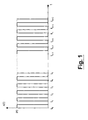
- Figure 1 shows a graph of a periodic signal x(t) with amplitude P0 and frequency fx.
- each period of the periodic signal x(t) starts with a rising edge.
- the normalised phase ⁇ x(t)/2 ⁇ of the signal x(t) is equal to an integer value, as shown in Figure 2.
- a counter is firstly provided.
- the counter value is increased upon each occurrence of an event marking the evolution of the data signal.
- Figure 2 shows for example a counter c(t) which is increased at each rising edge of the periodic signal x(t).
- the counter c(t) is equal to the normalised phase ⁇ x(t)/2 ⁇ with a phase error ⁇ (t).
- x(t) is a periodic signal.
- the method of measurement according to the present invention can be applied to data signals, i.e. to signals which comprise a sequence of bit with bit-rate fx.
- each bit “1” or “0” must be encoded so that in each period there occurs an event for incrementing the counter c(t). It is the case, for example, of bipolar encodings, wherein the bit "1” is encoded as a "high-low” transition and the bit "0” is encoded as a "low-high” transition. Therefore, independently of the bit sequence, each period includes a transition; the counter c(t) is then increased each time a transition occurs.
- fs sampling frequency
- the counter c(t) is the normalised phase ⁇ x(t)/2 ⁇ affected by an error ⁇ (t).
- the sampling frequency fs is such that the sampling instants always occur in the same position relatively to the signal periods, the phase error affecting each sample of the sequence ⁇ s n ⁇ is the same for all the samples.
- the sampling frequency fs is equal to fx or to an integer sub-multiple of the frequency fx, the sequence ⁇ s n ⁇ allows to recover the normalised phase ⁇ x(t)/2 ⁇ , shifted by a phase offset.
- Figure 3 shows an ideal case, in which fs is exactly equal to fx. It can be noticed that all the sampling instants are placed in the middle of each period; therefore, the sample sequence ⁇ s n ⁇ is a ramp, which is analogous to the normalised phase ⁇ x(t)/2 ⁇ ramp, shifted by a constant phase offset.
- fs is not exactly equal to fx (or to an integer sub-multiple of fx).
- the frequency fs is derived from the reference timing signal, thus being a sub-multiple of one of the synchronous hierarchy frequencies.
- the signal x(t) may be either a synchronous signal, or an asynchronous signal.
- the detuning between fs and fx may be of a few parts per million; in the second case, the detuning between fs and fx may be of a few percentage points.
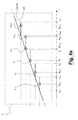
- Figures 4a and 4b show the effect of sampling in two real cases, wherein the sampling frequency fs and the frequency fx are detuned.
- Figure 4a refers to the case wherein fs is higher than fx. It is assumed that in a certain signal period, for example the period comprised between t n-3 e t n-2 , the sampling instant ts n-2 is placed in the middle of the period. As fs is higher than fx, in the following signal periods the sampling instants will tend to move towards the beginning of the period. Therefore, each sample of the sequence ⁇ S n ⁇ is affected by a phase error, with respect to the normalised phase ⁇ x(t)/2 ⁇ , that changes for each sample.
- sampling period 1/fs is lower than the signal period, after a certain number of sampling instants there will be a signal period (between t n e t n+1 in Figure 4a) comprising two sampling instants (ts n+1 e ts n+2 ).
- the resulting sample sequence ⁇ s n ⁇ thus exhibits an anomaly with respect to the linear trend of the normalised phase ramp.
- Figure 4b shows the case wherein fs is lower than fx.
- the sampling instant in a certain signal period, for instance the one included between t n-3 e t n-2 , the sampling instant is placed exactly in the middle of the signal period.
- the following sampling instants tend to move toward the end of the signal period.
- each sample of the sequence ⁇ S n ⁇ is affected by a different phase error.
- the sampling period 1/fs is higher than the signal period, after a certain number of sampling instants there will be a signal period (between t n e t n+1 in Figure 4b) comprising no sampling instants.
- the resulting sample sequence ⁇ S n ⁇ thus exhibits an anomaly with respect to the linear trend of the normalised phase ramp.
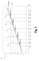
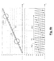
- Figures 5, 6a and 6b show the effect of the detuning between fs and fx over the phase error occurring when considering at each sampling instant ts n the sample s n instead of the actual value of normalised phase ⁇ x(ts n )/2 ⁇ , according to the known method.
- Figure 5 is referred to the ideal case wherein fs is equal to fx.
- Figures 6a and 6b are referred to two real cases wherein fs is respectively higher and lower than fx.
- Figure 6a shows a real case in which fs is higher than fx.
- the sample sequence ⁇ s n ⁇ exhibits anomalies, as described by reference to Figure 4a.
- Such anomalies are periodic with a period WTJ.
- the sequence of phase errors ⁇ n ⁇ has a saw-tooth shape with period WTJ. Filtering such a phase error thus requires filtering a 1/WTJ frequency component.
- Figure 6b shows a second real case in which fs is lower than fx.
- the sample sequence ⁇ s n ⁇ exhibits anomalies, as described by reference to Figure 4b.
- Such anomalies are periodic with a period WTJ.
- the sequence of phase errors ⁇ n ⁇ has a saw-tooth shape with period WTJ. Filtering such a phase error thus requires filtering a 1/WTJ frequency component.
- N ( 1 / fx ) / ⁇ T .
- sampling frequency fs it is not possible to modify the sampling frequency fs, as it is derived by the synchronous hierarchy frequencies by means of dividers, which provides integer sub-multiples of fs. Using a sub-multiple of fs, however, does not eliminate anomalies of the sequence ⁇ s n ⁇ and the consequent periodicity of the sequence of phase errors ⁇ n ⁇ .
- a method for digitally measuring the phase of a signal wherein the spectral distribution of the phase error can be modified.
- the method according to the invention comprise an additional step with respect to the known method, wherein the counter c(t) is sampled at a first sampling frequency fc uncorrelated from the signal frequency fx, thus obtaining a first sample sequence ⁇ c n ⁇ .
- Said first sample sequence ⁇ c n ⁇ is in turn sampled at a second sampling frequency fs, thus obtaining a second sample sequence ⁇ s n ⁇ , which is finally digitally processed.
- the second sequence ⁇ S n ⁇ exhibits anomalies with respect to the ramp of the normalised phase with a period WTJ mainly dependent on the ratio between the first sampling frequency fc and the signal frequency fx.
- WTJ the ratio between the first sampling frequency fc and the signal frequency fx.
- phase error ⁇ (t) phase error ⁇ (t).
- the sequence ( ⁇ n' ), represented by triangles in Figure 7, is the sequence of phase errors affecting the sequence ⁇ s n ⁇ in the ideal case, wherein fs is equal to fx.
- each phase error ⁇ n' affecting each sample s n is constant, the sequence ⁇ s n ⁇ thus corresponding to the normalised phase shifted by an offset.
- the sequence ⁇ n" ⁇ is the sequence of phase errors affecting the sequence ⁇ s n ⁇ in a real case, wherein fs and fx are detuned.
- the phase error ⁇ n" affecting each sample s n is not constant, and the sequence ⁇ n" ⁇ has period WTJ.
- the sequence ⁇ n"' ⁇ is the sequence of phase errors affecting the sequence ⁇ s n ⁇ in an embodiment of the method according to the present invention.
- the sequence ⁇ n"' ⁇ is not periodic, since the sampling time instants always fall in different positions of the signal period.
- the formulas describing ⁇ n"' ) will be derived.
- n ⁇ K ⁇ ⁇ ⁇ mn m + 1 + Km m + 1 ⁇ m + 1 m ⁇ n ⁇ .
- the sequence of phase errors when filtered, is substantially independent from K, i.e. from d; in other words, the sequence of phase errors is independent from the detuning between fs and fx.
- the first two terms of the summation are always integer numbers, while the third term provides a fractional number.
- the third term is an integer number only when multiplied by a number higher than m, i.e. the two following conditions must be satisfied:
- the filtered sequence ⁇ n "' ⁇ filt depends on m, which is related to the ratio between the first sampling frequency fc and the signal frequency fx.
- the weak dependence of the sequence on d is expressed by the term ⁇ .
- the maximum value of the phase error is about 2/m.
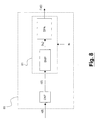
- FIG. 8 shows a known device for digitally measuring the phase of a signal.
- the device 80 comprises a counter block CNT, with an input port for receiving a signal, and an output port connected to the input port of a digital device 81, in turn comprising a sampler SMP connected to a processor DPA, which implements a digital processing algorithm.
- a signal x(t) at the input of the device 80 is received from the counter CNT, which outputs a counter c(t).
- Said counter c(t) is sent to the digital device 81, which is synchronised by a timing signal with frequency fs.
- the counter c(t) is firstly sampled by the sampler SMP with the sampling frequency fs, thus obtaining a sample sequence ⁇ S n ⁇ .
- the sampler then sends the sample sequence ⁇ S n ⁇ to the processor DPA, which digitally processes the sequence and possibly estimates the frequency of the input signal x(t).
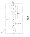
- FIG 9 shows a device for digitally measuring the phase of a signal according to the present invention.
- Said device is advantageously employed into a network element of a synchronous transmission network.
- the device 90 comprises a counter block CNT, with an input port for receiving a signal and an output port connected to an input port of a register RG.
- the register RG has an output port which is connected to an input of a digital device 91, in turn comprising a sampler SMP connected to a processor DPA, which implements a digital processing algorithm.
- a signal x(t) at the input of the device 90 is received by the counter block CNT, which extrapolates a counter c(t) from the signal x(t).
- Said counter c(t) is sent to the register RG, which samples it at a first sampling frequency fc, thus obtaining a first sample sequence ⁇ C n ⁇ .
- Said first sample sequence ⁇ C n ⁇ is sent to the digital device 91, which is synchronised by a timing signal with frequency fs.
- the sequence ⁇ C n ⁇ is firstly sampled by the sampler SMP with the sampling frequency fs, thus obtaining a sample sequence ⁇ S n ⁇ .
- the sampler then sends the sample sequence ⁇ S n ⁇ to the processor DPA, which digitally processes the sequence and possibly estimates the frequency of the input signal x(t).
- Such a device can be employed, for example, in network nodes of a synchronous network, as mentioned before.
- the frequency fs is obtained by a frequency of the synchronous hierarchy by suitable dividers, fs thus being an integer sub-multiple of a frequency of the synchronous hierarchy.
- fc is generated by a local oscillator uncorrelated from the timing signal available in the network element. This guarantees the uncorrelation between fc and fx.
- the device for digitally measuring the phase according to the invention can be employed into a device for the regeneration of a periodic signal x(t), and, more in particular, into devices such as the so-called “Phase Locked Loop” (PLL).
- Figure 10 shows a PLL 100 wherein the phase recovery is performed according to the method of the present invention.
- the PLL 100 comprises a phase device for phase digital measurement 101, a low-pass digital filter LPDF and a voltage-controlled local oscillator VCO.
- a junction 102 with two branches is provided, wherein a first branch is the output port of the PLL, while the second branch is connected to the device for phase digital measurement 101.
- the device for phase digital measurement 101 in turn comprises a phase detector PD, a register RG operating at a first sampling frequency fc and a sampler SMP working at a second sampling frequency fs.
- the PD outputs a signal proportional to the phase difference between x(t) and xloc(t).
- the phase difference is firstly sampled by the register RG at the frequency fc, and then by the sampler SMP at the frequency fs.
- the frequency fc is selected so that the sample sequence corresponding to the phase difference exhibits anomalies which can be easily filtered by the filter LPDF.
- the sample sequence corresponding to the phase difference is then digitally filtered by the filter LPDF.
- the filtered sequence is finally sent to the VCO.
- the VCO modifies its operation frequency; if the filtered sequence is a null sequence, the phases of x(t) and xloc(t) are equal, and the VCO does not modify its operating frequency.
Landscapes
- Engineering & Computer Science (AREA)
- Computer Networks & Wireless Communication (AREA)
- Signal Processing (AREA)
- Physics & Mathematics (AREA)
- General Physics & Mathematics (AREA)
- Synchronisation In Digital Transmission Systems (AREA)
- Measuring Phase Differences (AREA)
- Stabilization Of Oscillater, Synchronisation, Frequency Synthesizers (AREA)
Abstract
Description
- The present invention relates to the field of telecommunication networks and, in particular, to a method and a device for digitally measuring the phase of a signal.
- It is known that in a synchronous transmission network, e.g. SDH or Sonet, all the local timing signals are synchronized by a reference timing signal. Said reference timing signal propagates across the entire network and it is employed to synchronize all the nodes of the transmission network.
- In other words, a synchronous transmission network implements a "master-slave" synchronization scheme, wherein all the local timing signals (slave) of the single network nodes are recovered by locally regenerating a reference timing signal (master), which propagates across the network through the data flows.
- In order to be synchronised, a network element of a synchronous network (e.g. SDH or Sonet) is required to perform functions such as measurement of the reference frequency or regeneration of the reference timing signal. For a proper operation of the network, such functions must be performed by each network element as accurately as possible.
- For instance, the ITU-T Recommendation G.813 for SDH standard establishes the requirements of the frequency of the reference timing signal measured by each network element. For instance, the accuracy is fixed to 4,6 ppm for a 2048 kbit/s-operation optimised SDH hierarchy. The ITU-T Recommendation G.813 also defines the requirements of the locally-regenerated timing signals ("Slave Equipment Clock" or SEC), as a function of wander and jitter of the recovered signal phase. For instance, the maximum wander is 40 ns over a 0,1-1 s observation interval, while the maximum jitter is defined by a maximum peak-to-peak amplitude of 0,50 Ul over a 60 s interval with a band-pass filter having a 20 Hz-100 KHz passing band, for a 2048 kbit/s-operation optimised SDH hierarchy.
- Devices for phase measurement are known in the art, which can recover the phase of a signal both digitally or analogically. Said devices recover the phase as a function of time Γx(t) of an incoming signal x(t) and, optionally, they estimate its frequency fx by suitably processing the phase. In a synchronous transmission network, said devices for phase measurement can be employed into the network elements:
- for recovering the phase and/or frequency of an incoming signal x(t);
- for contributing to the regeneration of an incoming signal x(t).
- It has to be noticed that timing signals propagate across the network through data flows having bit-rate equal to the frequency of the timing signals. For simplicity, in the following description "signal x(t) with frequency fx" will indicate a data flow with bit-rate fx.
- In the first case (phase and/or frequency measurement), a device for phase measurement receives a signal x(t) and outputs, for example, the measurement of its frequency fx. In a network element, said device may for instance provide a measurement of the phase or frequency of the reference timing signal contained in the synchronous data flow; alternatively, said device may provide a measurement of the phase or frequency of an asynchronous data flow coming from asynchronous local networks connected to the synchronous network. In the first case (fx is the reference timing frequency), the measured frequency for example can be stored by the network element which can use it in case of need, for example when the network element eventually looses all the reference timing signals ("holdover operation" in SDH Recommendation ITU-T G.813). In the second case (fx is the frequency of an asynchronous signal), the measured frequency can be used to perform mapping/demapping of asynchronous tributaries into the synchronous numerical structures.
- As mentioned above, devices for phase measurement can contribute to the regeneration of an incoming signal x(t). Among regeneration devices, the Phase Locked Loop (or PLL) is one of the most widespread, thanks to the simplicity of its structure and the accuracy of the regenerated signal. A PLL receives a signal x(t) with a frequency fx and, by a proper feedback mechanism, the PLL outputs a local periodic signal xloc(t) having the same frequency fx of the signal x(t). In greater details, a PLL comprises a Phase Detector device and a Voltage Controlled Oscillator (or VCO) in a feedback configuration. The Phase Detector compares the phase of the incoming signal x(t) to the phase of the local signal xloc(t) generated by the VCO and propagating into the loop of the PLL. The phase error signal between the two compared signals is used to modify the operation frequency of the VCO. The PLL is "phase-locked" when the frequency of the local signal xloc(t) is equal to the frequency of the incoming signal x(t).
- For instance, in a synchronous network PLLs are placed into the network elements to recover a local timing signal (xloc(t)) from the synchronous data flow (x(t)). The local timing signal can then be used to synchronise the switching functions.
- As mentioned above, the devices for phase measurement can be digital or analog. For transmission network application, however, devices for phase measurement are preferably digital, for an easier integration with the other components of the network element, which mainly perform digital signal processing.
- A known method for digitally measuring the phase Γx(t) of a signal x(t) provides a counter which evolves at each event marking the evolution of the signal x(t). Afterwards, the counter is sampled at a sampling frequency fs. Ideally, if the frequency fs is equal to an integer sub-multiple of the frequency fx, the sample sequence allows to recover the phase as a function of time Γx(t).
- Nevertheless, in real operations the frequency fs is not exactly an integer sub-multiple of the frequency fx. For instance, the incoming signal x(t) may be an asynchronous data flow, whose frequency significantly differs from the synchronous frequencies synchronizing the network element, from which the frequency fs is derived. Alternatively, the incoming signal x(t) may be a synchronous data flow, whose bit-rate is affected by the aforementioned tolerance compliant with the Recommendation ITU-T G.813 (a few parts per million).
- In these cases, wherein a detuning occurs between the sampling frequency fs and the signal frequency fx, the measured phase is affected by a periodic error, for reasons which will be explained in details herein after. The period of the phase error increases by decreasing the detuning between fs and fx. For instance, with formulas that will be reported herein after, it is shown that when measuring the phase of an asynchronous signal with a frequency of the synchronous hierarchy (detuning of a few percentage points), the oscillation has a period of a few nanoseconds, corresponding to a spectral distribution of the order of 100 MHz, which is rather easy to filter. On the contrary, when measuring the phase of a synchronous signal through a frequency of the synchronous hierarchy (detuning of a few parts per million), the phase error has a period of a few seconds, corresponding to a spectral distribution in the Hz range, which cannot be filtered by a digital low-pass filter.
- The general object of the present invention is to provide a method and a device for digitally measuring the phase of a data signal in a transmission network which overcomes the aforesaid problem.
- In particular, an object of the present invention is to provide a method and a device for digitally measuring the phase of a data signal in a transmission network in which the phase error due to the detuning between the sampling frequency and the frequency of the signal under measurement has a spectral distribution which is independent from said detuning and which can be easily filtered by low-pass digital filters. Conveniently, such digital filters are similar to those already present into the network elements of a synchronous network.
- This and other objects are achieved, according to the present invention, by a method of digital measurement of phase of a data signal in a transmission network according to
claim 1, and by a device according to claim 7. Further advantageous features of the present invention are set forth into the respective dependent claims. All the claims are deemed to be an integral part of the present description. - According to the present invention, a method for digitally measuring the phase of a signal is provided, said method including an additional step compared with the known method, wherein the counter is sampled at a first sampling frequency uncorrelated from the frequency of the data signal. Said first sampling frequency can be expressed as fc= α fx, where α is an irrational number. With formulas which will be reported herein after, it is shown that the period and the amplitude of the phase error mainly depends on α ; in particular, if α is an irrational number, the phase error is aperiodic.
- Therefore, even though the detuning between fs and fx is of only a few parts per million, the phase error can be modified, as it now mainly depends on α . In particular, α can be chosen in order to shift the spectral distribution of the phase error towards a frequency range which can be easily filtered by an electronic low-pass filter.
- In a first aspect the present invention provides a method for digitally measuring the phase of a data signal with frequency fx in a transmission network. The method comprises the following steps: providing a counter; increasing the counter upon each occurrence of an event marking the evolution of the data signal with frequency fx and sampling the counter at a first sampling frequency fc, thus obtaining a first sample sequence. According to the method of the invention the first sample frequency fc is uncorrelated from the frequency fx. The method according to the invention further comprises the steps of sampling the first sample sequence at a second sampling frequency fs, thus obtaining a second sample sequence; and digitally processing said second sample sequence in order to estimate said phase of said data signal.
- Preferably, said counter is sampled at a frequency fc with fc=α·fx, where α is an irrational number.
- Preferably, the step of digitally processing said second sample sequence comprises digitally filtering said second sample sequence.
- Optionally, the step of digitally processing said second sample sequence comprises estimating said frequency fx of said data signal.
- Advantageously, said frequency fx of said data signal and said second sampling frequency fs are frequencies of a synchronous transmission system.
- Preferably, said first sampling frequency fc is generated by a local oscillator independent from said frequency fx and from said second sampling frequency fs.
- In a second aspect the present invention provides a device for digitally measuring the phase of a data signal with frequency fx in a transmission network. The device comprises: a counter block, said counter block increasing a counter upon each occurrence of an event marking the evolution of the data signal with frequency fx; and a register, said register sampling the counter at a first sampling frequency fc, thus obtaining a first sample sequence. According to the invention, the first sample frequency fc is uncorrelated from the frequency fx. In addition, the device further comprises: a sampler for sampling the first sample sequence at a second sampling frequency fs, thus obtaining a second sample sequence; and a processor for digitally processing the second sample sequence in order to estimate the phase of the data signal.
- Preferably, the register is a register sampling the counter at a first sampling frequency fc with fc=α ·fx, where α is an irrational number.
- Preferably, the processor digitally processes the second sample sequence by digitally filtering the second sample sequence.
- Optionally, the processor digitally processes the second sample sequence by estimating said frequency fx of said data signal.
- Advantageously, said device is a part of a Phase Locked Loop.
- Advantageously, said device is comprised in a network element.
- Further features and advantages of the present invention will become clear from by the following detailed description, given by way of example and not of limitation, to be read with reference to the accompanying drawings, wherein:
- Figure 1 shows a graph of a periodic signal x(t) with frequency fx;
- Figure 2 shows a graph of the normalised phase Γx(t)/2π of the signal x(t) and of the counter c(t) according to the known method;
- Figure 3 shows a graph of the normalised phase Γx(t)/2π of the signal x(t), of the counter c(t) and of the sample sequence {sn} according to the known method, in an ideal case in which fs is an integer sub-multiple of fx;
- Figures 4a and 4b show graphs of the normalised phase Γx(t)/2π of the signal x(t), of the counter c(t) and of the sample sequence {Sn} according to the known method, in a real case in which fs is respectively higher (Figure 4a) and lower (Figure 4b) than an integer sub-multiple of fx;
- Figure 5 shows a graph of the normalised phase Γx(t)/2π, of the counter c(t) and of the sample sequence {Sn} and a graph of the phase error ε(t) and of the phase error sequence {εn} according to the known method, in an ideal case in which fs is an integer sub-multiple of fx;
- Figure 6a e 6b show a graph the normalised phase Γx(t)/2π, of the counter c(t) and of the sample sequence {sn} and a graph of the phase error ε(t) and of the phase error sequence {εn} according to the known method, in real cases wherein fs is respectively higher (Figure 6a) and lower (Figure 6b) than an integer sub-multiple of fx;
- Figure 7 shows a graph of the phase error ε(t), of the phase error sequence {εn'} in the ideal case (fs equal to an integer sub-multiple of fx), of the phase error sequence {εn"} in a real case (detuning between fs and fx) according to the known method, and of the phase error sequence {εn"'} in a real case (detuning between fs and fx) according to the invention;
- Figure 8 shows the scheme of a known device for digital measurement of the phase of a signal;
- Figure 9 shows the scheme of a device for digital measurement of the phase of a signal according to the present invention; and
- Figure 10 shows a PLL comprising a device for digital measurement of the phase of a signal according to the present invention.
- In all the graphs representing a variable as a function of time (x(t), c(t), etc ...), the time scale is represented in arbitrary units.
- Figure 1 shows a graph of a periodic signal x(t) with amplitude P0 and frequency fx. The signal x(t) exhibits a rising edge at each instant t1, t2, ... tn, where t1=1/fx, t2=2/fx, ... tn=n/fx. In other words, each period of the periodic signal x(t) starts with a rising edge.
- It is known that the phase Γx(t) of the periodic signal x(t) evolves in time according to the relation Γx(t) = 2π·fx·t, i.e. Γx(t) is equal to an integer multiple of 2π in the time instants t1, t2, ... tn. Thus, in the time instants t1, t2, ... tn, wherein raising edges of the periodic signal x(t) occur, the normalised phase Γx(t)/2π of the signal x(t) is equal to an integer value, as shown in Figure 2. In particular, Γx(t1)/2π=1, Γx(t2)/2π=2, ... Γx(tn)/2π=n.
- As mentioned above, in a known method for digitally measuring the phase of a signal, a counter is firstly provided. The counter value is increased upon each occurrence of an event marking the evolution of the data signal. Figure 2 shows for example a counter c(t) which is increased at each rising edge of the periodic signal x(t). Hence:
- c(t)=0 where t0<t<t1;
- c(t)=1 where t1<t<t2;
- c(t)=2 where t2<t<t3; and, in general,
- c(t)=n where tn<t<tn+1.
- Comparing the normalised phase Γx(t)/2π with the counter c(t), it can be noticed that in each period the value of the counter c(t) is the integer part of the normalised phase Γx(t)/2π. Thus, the counter c(t) is equal to the normalised phase Γx(t)/2π with a phase error ε(t). The phase error ε(t) is the fractional part of the normalised phase Γx(t)/2π and it is defined as s(t)= Γx(t)/2π-c(t).
- It has to be noticed that, in the present description, x(t) is a periodic signal. Nevertheless, as mentioned above, the method of measurement according to the present invention can be applied to data signals, i.e. to signals which comprise a sequence of bit with bit-rate fx. To perform a digital measurement of the phase of this kind of signals, each bit "1" or "0" must be encoded so that in each period there occurs an event for incrementing the counter c(t). It is the case, for example, of bipolar encodings, wherein the bit "1" is encoded as a "high-low" transition and the bit "0" is encoded as a "low-high" transition. Therefore, independently of the bit sequence, each period includes a transition; the counter c(t) is then increased each time a transition occurs.
- The next step of the known method for measuring the phase of the signal x(t) comprises sampling the counter c(t) at a sampling frequency fs, i.e sampling the counter c(t) at a sequence of time instants {tsn} of sampling instants ts1, ts2, ... tsn. Two consecutive sampling instants tsn e tsn+1 are spaced by a sampling period Ts=1/fs. A sample sequence {sn} = s1, s2, ... sn is thus obtained. In particular, referring to Figure 3:
- at tsn-2 : sn-2=c(tsn-2);
- at tsn-1 : sn-1=c(tsn-1);
- at tsn : sn=c(tsn);
- at tsn+1 : sn+1=c(tsn+1); and
- at tsn+2 : Sn+2=c(tsn+2).
- As already mentioned, the counter c(t) is the normalised phase Γx(t)/2π affected by an error ε(t). However, if the sampling frequency fs is such that the sampling instants always occur in the same position relatively to the signal periods, the phase error affecting each sample of the sequence {sn} is the same for all the samples. In other words, if the sampling frequency fs is equal to fx or to an integer sub-multiple of the frequency fx, the sequence {sn} allows to recover the normalised phase Γx(t)/2π, shifted by a phase offset.
- In the following, for clarity reasons, only the case with sampling frequency fs equal to the frequency fx will be treated. Nevertheless, all the considerations may be applied to the more general case with fs integer sub-multiple of fx.
- Figure 3 shows an ideal case, in which fs is exactly equal to fx. It can be noticed that all the sampling instants are placed in the middle of each period; therefore, the sample sequence {sn} is a ramp, which is analogous to the normalised phase Γx(t)/2π ramp, shifted by a constant phase offset.
- However, in real cases fs is not exactly equal to fx (or to an integer sub-multiple of fx). For instance, in synchronous networks, the frequency fs is derived from the reference timing signal, thus being a sub-multiple of one of the synchronous hierarchy frequencies. The signal x(t) may be either a synchronous signal, or an asynchronous signal. As mentioned before, in the first case the detuning between fs and fx may be of a few parts per million; in the second case, the detuning between fs and fx may be of a few percentage points.
- Figures 4a and 4b show the effect of sampling in two real cases, wherein the sampling frequency fs and the frequency fx are detuned. In particular, Figure 4a refers to the case wherein fs is higher than fx. It is assumed that in a certain signal period, for example the period comprised between tn-3 e tn-2, the sampling instant tsn-2 is placed in the middle of the period. As fs is higher than fx, in the following signal periods the sampling instants will tend to move towards the beginning of the period. Therefore, each sample of the sequence {Sn} is affected by a phase error, with respect to the normalised phase Γx(t)/2π, that changes for each sample. Besides, as the
sampling period 1/fs is lower than the signal period, after a certain number of sampling instants there will be a signal period (between tn e tn+1 in Figure 4a) comprising two sampling instants (tsn+1 e tsn+2). The resulting sample sequence {sn} thus exhibits an anomaly with respect to the linear trend of the normalised phase ramp. - Similarly, Figure 4b shows the case wherein fs is lower than fx. Also in this case, in a certain signal period, for instance the one included between tn-3 e tn-2, the sampling instant is placed exactly in the middle of the signal period. As fs is lower than fx, the following sampling instants tend to move toward the end of the signal period. Hence, each sample of the sequence {Sn} is affected by a different phase error. Besides, as the
sampling period 1/fs is higher than the signal period, after a certain number of sampling instants there will be a signal period (between tn e tn+1 in Figure 4b) comprising no sampling instants. The resulting sample sequence {Sn} thus exhibits an anomaly with respect to the linear trend of the normalised phase ramp. - Figures 5, 6a and 6b show the effect of the detuning between fs and fx over the phase error occurring when considering at each sampling instant tsn the sample sn instead of the actual value of normalised phase Γx(tsn)/2π, according to the known method. In particular, Figure 5 is referred to the ideal case wherein fs is equal to fx. Figures 6a and 6b are referred to two real cases wherein fs is respectively higher and lower than fx.
- In Figure 5, it can be noticed, as mentioned by reference to Figure 3, that the sample sequence {Sn} has a linear trend, thus corresponding, except a phase offset, to the signal normalised phase. In other words, as shown in the lower graph of Figure 5, in this case the sequence of phase errors {εn} affecting the sequence {sn}, wherein each εn is defined as εn = Γx(tsn)/2π - sn, is constant.
- Figure 6a shows a real case in which fs is higher than fx. In this case, the sample sequence {sn} exhibits anomalies, as described by reference to Figure 4a. Such anomalies (highlighted by circles in Figure 6a) are periodic with a period WTJ. In other words, as shown in the lower graph of Figure 6a, in this case the sequence of phase errors {εn} has a saw-tooth shape with period WTJ. Filtering such a phase error thus requires filtering a 1/WTJ frequency component.
- Figure 6b shows a second real case in which fs is lower than fx. In this case, the sample sequence {sn} exhibits anomalies, as described by reference to Figure 4b. Such anomalies (highlighted by circles in Figure 6b) are periodic with a period WTJ. In other words, as shown in the lower graph of Figure 6b, in this case the sequence of phase errors {εn} has a saw-tooth shape with period WTJ. Filtering such a phase error thus requires filtering a 1/WTJ frequency component.
- It is possible to estimate the period WTJ of the sequence of phase errors through the formulas reported herein after.
- Under the assumption that fs can be expressed as fs=(1+s)·fx, in each period of the signal x(t), each sampling instant tsn moves, relatively to the corresponding signal period, of a time interval

- The number of signal periods required by the time instant to move across the entire signal period is

- Hence, an anomaly will occur when the sampling instant has passed through the whole period of the signal x(t), i.e.

- For instance, it is assumed that fs equal to 77 MHz. If the signal x(t) is a synchronous signal, s is equal to a few parts per million, according to the ITU-T Recommendation G.813. Thus,

- Digitally filtering such an anomaly requires filtering a spectral distribution placed at 1/ WTJ(synch) = 77 Hz. It is clear that such a filtering cannot be performed by a low-pass digital filter, as the frequency is too low.
- On the other hand, it is not possible to modify the sampling frequency fs, as it is derived by the synchronous hierarchy frequencies by means of dividers, which provides integer sub-multiples of fs. Using a sub-multiple of fs, however, does not eliminate anomalies of the sequence {sn} and the consequent periodicity of the sequence of phase errors {εn}.
- According to the present invention, a method for digitally measuring the phase of a signal is provided, wherein the spectral distribution of the phase error can be modified. Hence, the method according to the invention comprise an additional step with respect to the known method, wherein the counter c(t) is sampled at a first sampling frequency fc uncorrelated from the signal frequency fx, thus obtaining a first sample sequence {cn}. Said first sample sequence {cn} is in turn sampled at a second sampling frequency fs, thus obtaining a second sample sequence {sn}, which is finally digitally processed.
- With the method according to the invention, even though the detuning between fs and fx is very low, as in synchronous transmission system applications, the second sequence {Sn} exhibits anomalies with respect to the ramp of the normalised phase with a period WTJ mainly dependent on the ratio between the first sampling frequency fc and the signal frequency fx. In particular, if fc = α fx, with α irrational number, by suitably tailoring α it is possible to modify the sequence of phase errors {εn}.
- Actually, if α is an irrational number (i.e. fs and fx are uncorrelated), the sequence of phase errors {εn} becomes aperiodic. As mentioned referring to Figures 6a and 6b, if the ratio between fs and fx is a fractional value the anomalies of the sample sequence are periodic. On the contrary, as α is an irrational number, anomalies of the sample sequence {Cn} are not exactly periodic, as each sample cn which immediately follows an anomaly falls in a different position relatively to the signal period. Hence, anomalies are not exactly periodic in time, so the amplitude of the spectral distribution of the sequence of phase errors {εn} is reduced.
- For a deeper understanding of the invention, reference can be made to the above mentioned phase error ε(t). Reference will be now made to Figure 7, wherein a graph of the error as a function of time ε(t) is reported. The error ε(t), defined as ε(t) = Γx(t)/2π - c(t), has a periodic saw-tooth shape. The sequence (εn'), represented by triangles in Figure 7, is the sequence of phase errors affecting the sequence {sn} in the ideal case, wherein fs is equal to fx. As already mentioned, each phase error εn' affecting each sample sn is constant, the sequence {sn} thus corresponding to the normalised phase shifted by an offset. The sequence {εn"}, represented in Figure 7 by circles, is the sequence of phase errors affecting the sequence {sn} in a real case, wherein fs and fx are detuned. In this case, the phase error εn" affecting each sample sn is not constant, and the sequence {εn"} has period WTJ.
- The sequence {εn"'}, represented in Figure 7 by squares, is the sequence of phase errors affecting the sequence {sn} in an embodiment of the method according to the present invention. As already mentioned, the sequence {εn"'} is not periodic, since the sampling time instants always fall in different positions of the signal period. In the following, the formulas describing {εn"') will be derived.
- For simplicity, it will be assumed that α is an irrational number close to a fractional number q/p. Therefore Tc = p/q·Tx, while Ts = (1+d) Tx. Sampling the phase error ε(t) with a first sampling period Tc and then with a second sampling period Ts, the sequence {εn"'} can be expressed as:


- As d is in general very low, the term nd can be considered as a constant K. Therefore, the sequence of phase errors can be expressed as:

- It is now possible to demonstrate that the sequence of phase errors, when filtered, is substantially independent from K, i.e. from d; in other words, the sequence of phase errors is independent from the detuning between fs and fx. By digitally filtering the sequence {εn"'}, the filtered sequence {εn"'}filt can be written as:

- As the term of the summation is a periodic function with period m+1, it is possible to eliminate the dependence on i. Rewriting K as K=k+γ, where k is the integral part of k and γ is the fractional part of K, the filtered sequence can be further expressed as:

- It can be noticed that the first two terms of the summation are always integer numbers, while the third term provides a fractional number. The third term is an integer number only when multiplied by a number higher than m, i.e. the two following conditions must be satisfied:
- nm+γm ≥ m(m+1); and
- n ≥ m+(1-γ).
- Both these conditions are satisfied only when n=m+1, and, in this case, the third term is equal to 1. The filtered sequence can then be rewritten as:

- It can be noticed that:
-

-

- The final expression of the filtered sequence of phase errors is then:

- It can be noticed that the filtered sequence {εn"'}filt depends on m, which is related to the ratio between the first sampling frequency fc and the signal frequency fx. The weak dependence of the sequence on d is expressed by the term γ. It can also be noticed that while in the known method the phase error varies in a 0-1 range, in the method according to the present invention the maximum value of the phase error is about 2/m.
- Figure 8 shows a known device for digitally measuring the phase of a signal. The
device 80 comprises a counter block CNT, with an input port for receiving a signal, and an output port connected to the input port of adigital device 81, in turn comprising a sampler SMP connected to a processor DPA, which implements a digital processing algorithm. A signal x(t) at the input of thedevice 80 is received from the counter CNT, which outputs a counter c(t). Said counter c(t) is sent to thedigital device 81, which is synchronised by a timing signal with frequency fs. In thedigital device 81, the counter c(t) is firstly sampled by the sampler SMP with the sampling frequency fs, thus obtaining a sample sequence {Sn}. The sampler then sends the sample sequence {Sn} to the processor DPA, which digitally processes the sequence and possibly estimates the frequency of the input signal x(t). - Figure 9 shows a device for digitally measuring the phase of a signal according to the present invention. Said device is advantageously employed into a network element of a synchronous transmission network. The
device 90 comprises a counter block CNT, with an input port for receiving a signal and an output port connected to an input port of a register RG. The register RG has an output port which is connected to an input of adigital device 91, in turn comprising a sampler SMP connected to a processor DPA, which implements a digital processing algorithm. A signal x(t) at the input of thedevice 90 is received by the counter block CNT, which extrapolates a counter c(t) from the signal x(t). Said counter c(t) is sent to the register RG, which samples it at a first sampling frequency fc, thus obtaining a first sample sequence {Cn}. Said first sample sequence {Cn} is sent to thedigital device 91, which is synchronised by a timing signal with frequency fs. In thedigital device 91, the sequence {Cn} is firstly sampled by the sampler SMP with the sampling frequency fs, thus obtaining a sample sequence {Sn}. The sampler then sends the sample sequence {Sn} to the processor DPA, which digitally processes the sequence and possibly estimates the frequency of the input signal x(t). - Such a device can be employed, for example, in network nodes of a synchronous network, as mentioned before. In this application, the frequency fs is obtained by a frequency of the synchronous hierarchy by suitable dividers, fs thus being an integer sub-multiple of a frequency of the synchronous hierarchy. On the contrary, fc is generated by a local oscillator uncorrelated from the timing signal available in the network element. This guarantees the uncorrelation between fc and fx.
- As mentioned in the introduction, the device for digitally measuring the phase according to the invention can be employed into a device for the regeneration of a periodic signal x(t), and, more in particular, into devices such as the so-called "Phase Locked Loop" (PLL). Figure 10 shows a
PLL 100 wherein the phase recovery is performed according to the method of the present invention. ThePLL 100 comprises a phase device for phasedigital measurement 101, a low-pass digital filter LPDF and a voltage-controlled local oscillator VCO. At the output of the VCO, ajunction 102 with two branches is provided, wherein a first branch is the output port of the PLL, while the second branch is connected to the device for phasedigital measurement 101. The device for phasedigital measurement 101 in turn comprises a phase detector PD, a register RG operating at a first sampling frequency fc and a sampler SMP working at a second sampling frequency fs. - A signal x(t) with frequency fx at the input of the PLL s compared by the phase detector PD with the local signal xloc(t) coming from the VCO through the second branch of the
junction 102. The PD outputs a signal proportional to the phase difference between x(t) and xloc(t). The phase difference is firstly sampled by the register RG at the frequency fc, and then by the sampler SMP at the frequency fs. According to the present invention, the frequency fc is selected so that the sample sequence corresponding to the phase difference exhibits anomalies which can be easily filtered by the filter LPDF. The sample sequence corresponding to the phase difference is then digitally filtered by the filter LPDF. The filtered sequence is finally sent to the VCO. If this filtered sequence is different from a null sequence, the VCO modifies its operation frequency; if the filtered sequence is a null sequence, the phases of x(t) and xloc(t) are equal, and the VCO does not modify its operating frequency.
Claims (14)
- Method for digitally measuring the phase (Γx(t)) of a data signal (x(t)) with frequency fx in a transmission network, said method comprising:- providing a counter (c(t));- increasing said counter (c(t)) upon each occurrence of an event marking the evolution of the data signal (x(t)) with frequency fx;- sampling the counter (c(t)) at a first sampling frequency fc, thus obtaining a first sample sequence ({Cn}),- wherein said first sample frequency fc is uncorrelated from said frequency fx, and wherein the method further comprises:- sampling said first sample sequence ({Cn}) at a second sampling frequency fs, thus obtaining a second sample sequence ({sn}); and- digitally processing said second sample sequence ({sn}) in order to estimate said phase (Γx(t)) of said data signal (x(t)).
- Method according to claim 1, wherein the step of sampling said counter (c(t)) at said first sampling frequency fc uncorrelated from said frequency fx comprises sampling said counter (c(t)) at said frequency fc with fc=α ·fx, where α is an irrational number.
- Method according to any of claims 1 or 2, wherein the step of digitally processing said second sample sequence ({Sn}) comprises digitally filtering said second sample sequence ({Sn}).
- Method according to any of claims 1-3, wherein the step of digitally processing said second sample sequence ({Sn}) comprises estimating said frequency fx of said data signal (x(t)).
- Method according to any of preceding claims, wherein said frequency fx of said data signal (x(t)) and said second sampling frequency fs are frequencies of a synchronous transmission system.
- Method according to any of preceding claims, wherein said first sampling frequency fc is generated by a local oscillator independent from said frequency fx and from said second sampling frequency fs.
- Device for digitally measuring the phase (Γx(t)) of a data signal (x(t)) with frequency fx in a transmission network, said device comprising:- a counter block (CNT), said counter block (CNT) increasing a counter (c(t)) upon each occurrence of an event marking the evolution of the data signal (x(t)) with frequency fx; and- a register (RG), said register (RG) sampling the counter (c(t)) at a first sampling frequency fc, thus obtaining a first sample sequence ({cn}),- wherein said first sample frequency fc is uncorrelated from said frequency fx, and wherein said device further comprises:- a sampler (SMP), said sampler (SMP) sampling said first sample sequence ({Cn}) at a second sampling frequency fs, thus obtaining a second sample sequence ({Sn}); and- a processor (DPA), said processor (DPA) digitally processing said second sample sequence ({Sn}) in order to estimate said phase (Γx(t)) of said data signal (x(t)).
- Device according to claim 7, wherein said register (RG) is a register sampling the counter (c(t)) at a first sampling frequency fc with fc=α·fx, where α is an irrational number.
- Device according to any of claims 7 or 8, wherein said processor (DPA) digitally processes said second sample sequence ({sn}) by digitally filtering said second sample sequence ({sn}).
- Device according to any of claims 7-9, wherein said processor (DPA) digitally processes said second sample sequence ({sn}) estimating said frequency fx of said data signal (x(t)).
- Device according to any of claims 7-10, wherein said frequency fx of the data signal (x(t)) and said second sampling frequency fs are frequencies of a synchronous transmission system.
- Device according to any of claims 7-11, wherein said first sampling frequency fc is generated by a local oscillator independent from said frequency fx and from said second sampling frequency fs.
- Device according to any of claims 7-12, wherein said device is a part of a Phase Locked Loop (100).
- Network element comprising a device according to any of claims 7-13.
Priority Applications (5)
| Application Number | Priority Date | Filing Date | Title |
|---|---|---|---|
| AT04292278T ATE507483T1 (en) | 2004-09-22 | 2004-09-22 | METHOD AND DEVICE FOR DIGITAL PHASE MEASUREMENT OF A SIGNAL |
| DE602004032438T DE602004032438D1 (en) | 2004-09-22 | 2004-09-22 | Method and device for digital phase measurement of a signal |
| EP04292278A EP1640733B1 (en) | 2004-09-22 | 2004-09-22 | Method and device for digitally measuring the phase of a signal |
| US11/192,357 US20060061393A1 (en) | 2004-09-22 | 2005-07-29 | Method and device for digitally measuring the phase of a signal |
| CN200510103568.7A CN1753311A (en) | 2004-09-22 | 2005-09-21 | Method and device for digitally measuring the phase of a signal |
Applications Claiming Priority (1)
| Application Number | Priority Date | Filing Date | Title |
|---|---|---|---|
| EP04292278A EP1640733B1 (en) | 2004-09-22 | 2004-09-22 | Method and device for digitally measuring the phase of a signal |
Publications (2)
| Publication Number | Publication Date |
|---|---|
| EP1640733A1 true EP1640733A1 (en) | 2006-03-29 |
| EP1640733B1 EP1640733B1 (en) | 2011-04-27 |
Family
ID=34931406
Family Applications (1)
| Application Number | Title | Priority Date | Filing Date |
|---|---|---|---|
| EP04292278A Expired - Lifetime EP1640733B1 (en) | 2004-09-22 | 2004-09-22 | Method and device for digitally measuring the phase of a signal |
Country Status (5)
| Country | Link |
|---|---|
| US (1) | US20060061393A1 (en) |
| EP (1) | EP1640733B1 (en) |
| CN (1) | CN1753311A (en) |
| AT (1) | ATE507483T1 (en) |
| DE (1) | DE602004032438D1 (en) |
Families Citing this family (2)
| Publication number | Priority date | Publication date | Assignee | Title |
|---|---|---|---|---|
| EP2282229A1 (en) * | 2009-08-07 | 2011-02-09 | CCS Technology, Inc. | Connectorized optical assembly and method for connecting optical transceiver units by an optical assembly |
| US8890507B2 (en) * | 2010-05-19 | 2014-11-18 | Tektronix, Inc. | Phase transient response measurements using automatic frequency estimation |
Citations (5)
| Publication number | Priority date | Publication date | Assignee | Title |
|---|---|---|---|---|
| EP0446190A2 (en) * | 1990-03-08 | 1991-09-11 | Telefonaktiebolaget L M Ericsson | Direct phase digitization |
| EP0637137A2 (en) * | 1993-07-28 | 1995-02-01 | Motorola, Inc. | Low-power, jitter-compensated phase locked loop and method therefor |
| DE4336240A1 (en) * | 1993-10-23 | 1995-04-27 | Sel Alcatel Ag | Circuit arrangement for a digital phase comparator |
| US6246738B1 (en) * | 1998-11-19 | 2001-06-12 | Pmc-Sierra Ltd. | Phase modulated reduction of clock wander in synchronous wide area networks |
| US6266799B1 (en) * | 1997-10-02 | 2001-07-24 | Xaqti, Corporation | Multi-phase data/clock recovery circuitry and methods for implementing same |
-
2004
- 2004-09-22 EP EP04292278A patent/EP1640733B1/en not_active Expired - Lifetime
- 2004-09-22 DE DE602004032438T patent/DE602004032438D1/en not_active Expired - Lifetime
- 2004-09-22 AT AT04292278T patent/ATE507483T1/en not_active IP Right Cessation
-
2005
- 2005-07-29 US US11/192,357 patent/US20060061393A1/en not_active Abandoned
- 2005-09-21 CN CN200510103568.7A patent/CN1753311A/en active Pending
Patent Citations (5)
| Publication number | Priority date | Publication date | Assignee | Title |
|---|---|---|---|---|
| EP0446190A2 (en) * | 1990-03-08 | 1991-09-11 | Telefonaktiebolaget L M Ericsson | Direct phase digitization |
| EP0637137A2 (en) * | 1993-07-28 | 1995-02-01 | Motorola, Inc. | Low-power, jitter-compensated phase locked loop and method therefor |
| DE4336240A1 (en) * | 1993-10-23 | 1995-04-27 | Sel Alcatel Ag | Circuit arrangement for a digital phase comparator |
| US6266799B1 (en) * | 1997-10-02 | 2001-07-24 | Xaqti, Corporation | Multi-phase data/clock recovery circuitry and methods for implementing same |
| US6246738B1 (en) * | 1998-11-19 | 2001-06-12 | Pmc-Sierra Ltd. | Phase modulated reduction of clock wander in synchronous wide area networks |
Also Published As
| Publication number | Publication date |
|---|---|
| EP1640733B1 (en) | 2011-04-27 |
| ATE507483T1 (en) | 2011-05-15 |
| DE602004032438D1 (en) | 2011-06-09 |
| US20060061393A1 (en) | 2006-03-23 |
| CN1753311A (en) | 2006-03-29 |
Similar Documents
| Publication | Publication Date | Title |
|---|---|---|
| EP1178609B1 (en) | Phase detector | |
| US7272201B2 (en) | System for synchronous sampling and time-of-day clocking using an encoded time signal | |
| US6326851B1 (en) | Digital phase-domain PLL frequency synthesizer | |
| KR100547831B1 (en) | Clock and data recovery device capable of responding to variable data rates | |
| JP5471962B2 (en) | Clock data recovery circuit and clock data recovery method | |
| EP3301835A1 (en) | Apparatus and methods for asynchronous clock mapping | |
| KR101054638B1 (en) | Data reproduction circuit | |
| JPH0828702B2 (en) | Clock regenerator | |
| US6246738B1 (en) | Phase modulated reduction of clock wander in synchronous wide area networks | |
| JP5002528B2 (en) | Digital phase detector and PLL | |
| US20170187481A1 (en) | Fail safe clock buffer and clock generator | |
| US9444615B2 (en) | Low latency digital jitter termination for repeater circuits | |
| US7642862B2 (en) | Digital phase locked loop | |
| Cosart et al. | Time domain analysis and its practical application to the measurement of phase noise and jitter | |
| US8433000B2 (en) | Method and circuit for receiving data | |
| JP4195239B2 (en) | Jitter measuring device | |
| CN103983296A (en) | Method for detecting measurement value | |
| EP1640733B1 (en) | Method and device for digitally measuring the phase of a signal | |
| CN113839670A (en) | High-performance frequency correction method, frequency correction system and improved phase-locked loop | |
| EP4102765A1 (en) | Time synchronization device, time synchronization system, and time synchronization method | |
| CN106067811A (en) | A kind of Bang Bang phase discriminator being applied to subrate clock data recovery circuit | |
| US5495204A (en) | Digital FM demodulator and method with enhanced resolution | |
| US20040071168A1 (en) | System and method for providing network timing recovery | |
| CN1209897C (en) | Method of detecting pilot tones in noisy signal | |
| Gautam et al. | Double demodulation type open-loop synchronization method for single-phase system |
Legal Events
| Date | Code | Title | Description |
|---|---|---|---|
| PUAI | Public reference made under article 153(3) epc to a published international application that has entered the european phase |
Free format text: ORIGINAL CODE: 0009012 |
|
| AK | Designated contracting states |
Kind code of ref document: A1 Designated state(s): AT BE BG CH CY CZ DE DK EE ES FI FR GB GR HU IE IT LI LU MC NL PL PT RO SE SI SK TR |
|
| AX | Request for extension of the european patent |
Extension state: AL HR LT LV MK |
|
| 17P | Request for examination filed |
Effective date: 20060928 |
|
| RIN1 | Information on inventor provided before grant (corrected) |
Inventor name: RAZZETTI, LUCA Inventor name: GASTALDELLO, STEFANO Inventor name: SKERLJ, MAURIZIO |
|
| 17Q | First examination report despatched |
Effective date: 20061026 |
|
| AKX | Designation fees paid |
Designated state(s): AT BE BG CH CY CZ DE DK EE ES FI FR GB GR HU IE IT LI LU MC NL PL PT RO SE SI SK TR |
|
| RAP1 | Party data changed (applicant data changed or rights of an application transferred) |
Owner name: ALCATEL LUCENT |
|
| GRAP | Despatch of communication of intention to grant a patent |
Free format text: ORIGINAL CODE: EPIDOSNIGR1 |
|
| GRAS | Grant fee paid |
Free format text: ORIGINAL CODE: EPIDOSNIGR3 |
|
| GRAA | (expected) grant |
Free format text: ORIGINAL CODE: 0009210 |
|
| AK | Designated contracting states |
Kind code of ref document: B1 Designated state(s): AT BE BG CH CY CZ DE DK EE ES FI FR GB GR HU IE IT LI LU MC NL PL PT RO SE SI SK TR |
|
| REG | Reference to a national code |
Ref country code: GB Ref legal event code: FG4D |
|
| REG | Reference to a national code |
Ref country code: CH Ref legal event code: EP |
|
| REG | Reference to a national code |
Ref country code: IE Ref legal event code: FG4D |
|
| REF | Corresponds to: |
Ref document number: 602004032438 Country of ref document: DE Date of ref document: 20110609 Kind code of ref document: P |
|
| REG | Reference to a national code |
Ref country code: DE Ref legal event code: R096 Ref document number: 602004032438 Country of ref document: DE Effective date: 20110609 |
|
| REG | Reference to a national code |
Ref country code: NL Ref legal event code: VDEP Effective date: 20110427 |
|
| PG25 | Lapsed in a contracting state [announced via postgrant information from national office to epo] |
Ref country code: SE Free format text: LAPSE BECAUSE OF FAILURE TO SUBMIT A TRANSLATION OF THE DESCRIPTION OR TO PAY THE FEE WITHIN THE PRESCRIBED TIME-LIMIT Effective date: 20110427 Ref country code: PT Free format text: LAPSE BECAUSE OF FAILURE TO SUBMIT A TRANSLATION OF THE DESCRIPTION OR TO PAY THE FEE WITHIN THE PRESCRIBED TIME-LIMIT Effective date: 20110829 |
|
| PG25 | Lapsed in a contracting state [announced via postgrant information from national office to epo] |
Ref country code: SI Free format text: LAPSE BECAUSE OF FAILURE TO SUBMIT A TRANSLATION OF THE DESCRIPTION OR TO PAY THE FEE WITHIN THE PRESCRIBED TIME-LIMIT Effective date: 20110427 Ref country code: CY Free format text: LAPSE BECAUSE OF FAILURE TO SUBMIT A TRANSLATION OF THE DESCRIPTION OR TO PAY THE FEE WITHIN THE PRESCRIBED TIME-LIMIT Effective date: 20110427 Ref country code: FI Free format text: LAPSE BECAUSE OF FAILURE TO SUBMIT A TRANSLATION OF THE DESCRIPTION OR TO PAY THE FEE WITHIN THE PRESCRIBED TIME-LIMIT Effective date: 20110427 Ref country code: ES Free format text: LAPSE BECAUSE OF FAILURE TO SUBMIT A TRANSLATION OF THE DESCRIPTION OR TO PAY THE FEE WITHIN THE PRESCRIBED TIME-LIMIT Effective date: 20110807 Ref country code: BE Free format text: LAPSE BECAUSE OF FAILURE TO SUBMIT A TRANSLATION OF THE DESCRIPTION OR TO PAY THE FEE WITHIN THE PRESCRIBED TIME-LIMIT Effective date: 20110427 Ref country code: GR Free format text: LAPSE BECAUSE OF FAILURE TO SUBMIT A TRANSLATION OF THE DESCRIPTION OR TO PAY THE FEE WITHIN THE PRESCRIBED TIME-LIMIT Effective date: 20110728 Ref country code: AT Free format text: LAPSE BECAUSE OF FAILURE TO SUBMIT A TRANSLATION OF THE DESCRIPTION OR TO PAY THE FEE WITHIN THE PRESCRIBED TIME-LIMIT Effective date: 20110427 |
|
| PG25 | Lapsed in a contracting state [announced via postgrant information from national office to epo] |
Ref country code: NL Free format text: LAPSE BECAUSE OF FAILURE TO SUBMIT A TRANSLATION OF THE DESCRIPTION OR TO PAY THE FEE WITHIN THE PRESCRIBED TIME-LIMIT Effective date: 20110427 |
|
| PG25 | Lapsed in a contracting state [announced via postgrant information from national office to epo] |
Ref country code: CZ Free format text: LAPSE BECAUSE OF FAILURE TO SUBMIT A TRANSLATION OF THE DESCRIPTION OR TO PAY THE FEE WITHIN THE PRESCRIBED TIME-LIMIT Effective date: 20110427 Ref country code: EE Free format text: LAPSE BECAUSE OF FAILURE TO SUBMIT A TRANSLATION OF THE DESCRIPTION OR TO PAY THE FEE WITHIN THE PRESCRIBED TIME-LIMIT Effective date: 20110427 |
|
| RAP2 | Party data changed (patent owner data changed or rights of a patent transferred) |
Owner name: ALCATEL LUCENT |
|
| PG25 | Lapsed in a contracting state [announced via postgrant information from national office to epo] |
Ref country code: SK Free format text: LAPSE BECAUSE OF FAILURE TO SUBMIT A TRANSLATION OF THE DESCRIPTION OR TO PAY THE FEE WITHIN THE PRESCRIBED TIME-LIMIT Effective date: 20110427 Ref country code: PL Free format text: LAPSE BECAUSE OF FAILURE TO SUBMIT A TRANSLATION OF THE DESCRIPTION OR TO PAY THE FEE WITHIN THE PRESCRIBED TIME-LIMIT Effective date: 20110427 Ref country code: DK Free format text: LAPSE BECAUSE OF FAILURE TO SUBMIT A TRANSLATION OF THE DESCRIPTION OR TO PAY THE FEE WITHIN THE PRESCRIBED TIME-LIMIT Effective date: 20110427 Ref country code: RO Free format text: LAPSE BECAUSE OF FAILURE TO SUBMIT A TRANSLATION OF THE DESCRIPTION OR TO PAY THE FEE WITHIN THE PRESCRIBED TIME-LIMIT Effective date: 20110427 |
|
| REG | Reference to a national code |
Ref country code: CH Ref legal event code: PCOW Free format text: ALCATEL LUCENT;3, AVENUE OCTAVE GREARD;75007 PARIS (FR) |
|
| PLBE | No opposition filed within time limit |
Free format text: ORIGINAL CODE: 0009261 |
|
| STAA | Information on the status of an ep patent application or granted ep patent |
Free format text: STATUS: NO OPPOSITION FILED WITHIN TIME LIMIT |
|
| 26N | No opposition filed |
Effective date: 20120130 |
|
| PG25 | Lapsed in a contracting state [announced via postgrant information from national office to epo] |
Ref country code: MC Free format text: LAPSE BECAUSE OF NON-PAYMENT OF DUE FEES Effective date: 20110930 |
|
| REG | Reference to a national code |
Ref country code: CH Ref legal event code: PL |
|
| REG | Reference to a national code |
Ref country code: DE Ref legal event code: R097 Ref document number: 602004032438 Country of ref document: DE Effective date: 20120130 |
|
| PG25 | Lapsed in a contracting state [announced via postgrant information from national office to epo] |
Ref country code: IT Free format text: LAPSE BECAUSE OF FAILURE TO SUBMIT A TRANSLATION OF THE DESCRIPTION OR TO PAY THE FEE WITHIN THE PRESCRIBED TIME-LIMIT Effective date: 20110427 |
|
| REG | Reference to a national code |
Ref country code: IE Ref legal event code: MM4A |
|
| PG25 | Lapsed in a contracting state [announced via postgrant information from national office to epo] |
Ref country code: IE Free format text: LAPSE BECAUSE OF NON-PAYMENT OF DUE FEES Effective date: 20110922 Ref country code: CH Free format text: LAPSE BECAUSE OF NON-PAYMENT OF DUE FEES Effective date: 20110930 Ref country code: LI Free format text: LAPSE BECAUSE OF NON-PAYMENT OF DUE FEES Effective date: 20110930 |
|
| PG25 | Lapsed in a contracting state [announced via postgrant information from national office to epo] |
Ref country code: LU Free format text: LAPSE BECAUSE OF NON-PAYMENT OF DUE FEES Effective date: 20110922 |
|
| PG25 | Lapsed in a contracting state [announced via postgrant information from national office to epo] |
Ref country code: BG Free format text: LAPSE BECAUSE OF FAILURE TO SUBMIT A TRANSLATION OF THE DESCRIPTION OR TO PAY THE FEE WITHIN THE PRESCRIBED TIME-LIMIT Effective date: 20110727 |
|
| PG25 | Lapsed in a contracting state [announced via postgrant information from national office to epo] |
Ref country code: TR Free format text: LAPSE BECAUSE OF FAILURE TO SUBMIT A TRANSLATION OF THE DESCRIPTION OR TO PAY THE FEE WITHIN THE PRESCRIBED TIME-LIMIT Effective date: 20110427 |
|
| PG25 | Lapsed in a contracting state [announced via postgrant information from national office to epo] |
Ref country code: HU Free format text: LAPSE BECAUSE OF FAILURE TO SUBMIT A TRANSLATION OF THE DESCRIPTION OR TO PAY THE FEE WITHIN THE PRESCRIBED TIME-LIMIT Effective date: 20110427 |
|
| REG | Reference to a national code |
Ref country code: FR Ref legal event code: GC Effective date: 20131018 |
|
| REG | Reference to a national code |
Ref country code: FR Ref legal event code: RG Effective date: 20141016 |
|
| REG | Reference to a national code |
Ref country code: FR Ref legal event code: PLFP Year of fee payment: 12 |
|
| PGFP | Annual fee paid to national office [announced via postgrant information from national office to epo] |
Ref country code: GB Payment date: 20150917 Year of fee payment: 12 Ref country code: DE Payment date: 20150922 Year of fee payment: 12 |
|
| PGFP | Annual fee paid to national office [announced via postgrant information from national office to epo] |
Ref country code: FR Payment date: 20150922 Year of fee payment: 12 |
|
| REG | Reference to a national code |
Ref country code: DE Ref legal event code: R119 Ref document number: 602004032438 Country of ref document: DE |
|
| GBPC | Gb: european patent ceased through non-payment of renewal fee |
Effective date: 20160922 |
|
| REG | Reference to a national code |
Ref country code: FR Ref legal event code: ST Effective date: 20170531 |
|
| PG25 | Lapsed in a contracting state [announced via postgrant information from national office to epo] |
Ref country code: GB Free format text: LAPSE BECAUSE OF NON-PAYMENT OF DUE FEES Effective date: 20160922 Ref country code: DE Free format text: LAPSE BECAUSE OF NON-PAYMENT OF DUE FEES Effective date: 20170401 Ref country code: FR Free format text: LAPSE BECAUSE OF NON-PAYMENT OF DUE FEES Effective date: 20160930 |