EP1640570A1 - Electromagnetic valve unit and engine cover unit - Google Patents
Electromagnetic valve unit and engine cover unit Download PDFInfo
- Publication number
- EP1640570A1 EP1640570A1 EP05020470A EP05020470A EP1640570A1 EP 1640570 A1 EP1640570 A1 EP 1640570A1 EP 05020470 A EP05020470 A EP 05020470A EP 05020470 A EP05020470 A EP 05020470A EP 1640570 A1 EP1640570 A1 EP 1640570A1
- Authority
- EP
- European Patent Office
- Prior art keywords
- electromagnetic valve
- housing
- valve unit
- electromagnetic
- hydraulic
- Prior art date
- Legal status (The legal status is an assumption and is not a legal conclusion. Google has not performed a legal analysis and makes no representation as to the accuracy of the status listed.)
- Withdrawn
Links
- 239000003921 oil Substances 0.000 claims abstract description 45
- 239000010720 hydraulic oil Substances 0.000 claims abstract description 36
- 230000007246 mechanism Effects 0.000 claims abstract description 15
- 238000001914 filtration Methods 0.000 claims description 23
- 239000012530 fluid Substances 0.000 description 37
- 238000000034 method Methods 0.000 description 6
- 238000012423 maintenance Methods 0.000 description 4
- 230000001771 impaired effect Effects 0.000 description 3
- 241001481828 Glyptocephalus cynoglossus Species 0.000 description 2
- 230000003247 decreasing effect Effects 0.000 description 2
- 238000005266 casting Methods 0.000 description 1
Images


Classifications
-
- F—MECHANICAL ENGINEERING; LIGHTING; HEATING; WEAPONS; BLASTING
- F01—MACHINES OR ENGINES IN GENERAL; ENGINE PLANTS IN GENERAL; STEAM ENGINES
- F01L—CYCLICALLY OPERATING VALVES FOR MACHINES OR ENGINES
- F01L1/00—Valve-gear or valve arrangements, e.g. lift-valve gear
- F01L1/34—Valve-gear or valve arrangements, e.g. lift-valve gear characterised by the provision of means for changing the timing of the valves without changing the duration of opening and without affecting the magnitude of the valve lift
- F01L1/344—Valve-gear or valve arrangements, e.g. lift-valve gear characterised by the provision of means for changing the timing of the valves without changing the duration of opening and without affecting the magnitude of the valve lift changing the angular relationship between crankshaft and camshaft, e.g. using helicoidal gear
-
- F—MECHANICAL ENGINEERING; LIGHTING; HEATING; WEAPONS; BLASTING
- F02—COMBUSTION ENGINES; HOT-GAS OR COMBUSTION-PRODUCT ENGINE PLANTS
- F02F—CYLINDERS, PISTONS OR CASINGS, FOR COMBUSTION ENGINES; ARRANGEMENTS OF SEALINGS IN COMBUSTION ENGINES
- F02F7/00—Casings, e.g. crankcases
- F02F7/006—Camshaft or pushrod housings
-
- F—MECHANICAL ENGINEERING; LIGHTING; HEATING; WEAPONS; BLASTING
- F01—MACHINES OR ENGINES IN GENERAL; ENGINE PLANTS IN GENERAL; STEAM ENGINES
- F01L—CYCLICALLY OPERATING VALVES FOR MACHINES OR ENGINES
- F01L1/00—Valve-gear or valve arrangements, e.g. lift-valve gear
- F01L1/02—Valve drive
- F01L1/04—Valve drive by means of cams, camshafts, cam discs, eccentrics or the like
- F01L1/047—Camshafts
- F01L1/053—Camshafts overhead type
- F01L2001/0537—Double overhead camshafts [DOHC]
-
- F—MECHANICAL ENGINEERING; LIGHTING; HEATING; WEAPONS; BLASTING
- F01—MACHINES OR ENGINES IN GENERAL; ENGINE PLANTS IN GENERAL; STEAM ENGINES
- F01L—CYCLICALLY OPERATING VALVES FOR MACHINES OR ENGINES
- F01L1/00—Valve-gear or valve arrangements, e.g. lift-valve gear
- F01L1/34—Valve-gear or valve arrangements, e.g. lift-valve gear characterised by the provision of means for changing the timing of the valves without changing the duration of opening and without affecting the magnitude of the valve lift
- F01L1/344—Valve-gear or valve arrangements, e.g. lift-valve gear characterised by the provision of means for changing the timing of the valves without changing the duration of opening and without affecting the magnitude of the valve lift changing the angular relationship between crankshaft and camshaft, e.g. using helicoidal gear
- F01L1/3442—Valve-gear or valve arrangements, e.g. lift-valve gear characterised by the provision of means for changing the timing of the valves without changing the duration of opening and without affecting the magnitude of the valve lift changing the angular relationship between crankshaft and camshaft, e.g. using helicoidal gear using hydraulic chambers with variable volume to transmit the rotating force
- F01L2001/34423—Details relating to the hydraulic feeding circuit
- F01L2001/34426—Oil control valves
- F01L2001/3443—Solenoid driven oil control valves
-
- F—MECHANICAL ENGINEERING; LIGHTING; HEATING; WEAPONS; BLASTING
- F01—MACHINES OR ENGINES IN GENERAL; ENGINE PLANTS IN GENERAL; STEAM ENGINES
- F01L—CYCLICALLY OPERATING VALVES FOR MACHINES OR ENGINES
- F01L1/00—Valve-gear or valve arrangements, e.g. lift-valve gear
- F01L1/34—Valve-gear or valve arrangements, e.g. lift-valve gear characterised by the provision of means for changing the timing of the valves without changing the duration of opening and without affecting the magnitude of the valve lift
- F01L1/344—Valve-gear or valve arrangements, e.g. lift-valve gear characterised by the provision of means for changing the timing of the valves without changing the duration of opening and without affecting the magnitude of the valve lift changing the angular relationship between crankshaft and camshaft, e.g. using helicoidal gear
- F01L1/3442—Valve-gear or valve arrangements, e.g. lift-valve gear characterised by the provision of means for changing the timing of the valves without changing the duration of opening and without affecting the magnitude of the valve lift changing the angular relationship between crankshaft and camshaft, e.g. using helicoidal gear using hydraulic chambers with variable volume to transmit the rotating force
- F01L2001/34423—Details relating to the hydraulic feeding circuit
- F01L2001/34426—Oil control valves
- F01L2001/34433—Location oil control valves
-
- F—MECHANICAL ENGINEERING; LIGHTING; HEATING; WEAPONS; BLASTING
- F01—MACHINES OR ENGINES IN GENERAL; ENGINE PLANTS IN GENERAL; STEAM ENGINES
- F01L—CYCLICALLY OPERATING VALVES FOR MACHINES OR ENGINES
- F01L1/00—Valve-gear or valve arrangements, e.g. lift-valve gear
- F01L1/34—Valve-gear or valve arrangements, e.g. lift-valve gear characterised by the provision of means for changing the timing of the valves without changing the duration of opening and without affecting the magnitude of the valve lift
- F01L1/344—Valve-gear or valve arrangements, e.g. lift-valve gear characterised by the provision of means for changing the timing of the valves without changing the duration of opening and without affecting the magnitude of the valve lift changing the angular relationship between crankshaft and camshaft, e.g. using helicoidal gear
- F01L1/3442—Valve-gear or valve arrangements, e.g. lift-valve gear characterised by the provision of means for changing the timing of the valves without changing the duration of opening and without affecting the magnitude of the valve lift changing the angular relationship between crankshaft and camshaft, e.g. using helicoidal gear using hydraulic chambers with variable volume to transmit the rotating force
- F01L2001/34423—Details relating to the hydraulic feeding circuit
- F01L2001/34436—Features or method for avoiding malfunction due to foreign matters in oil
- F01L2001/3444—Oil filters
Definitions
- This invention generally relates to an alignment structure for an electromagnetic valve. More particularly, this invention relates to an alignment for an electromagnetic valve in which at least two electromagnetic valves are aligned at a hydraulic circuit.
- VVT variable valve timing control device
- oil paths are connected to solenoid valves from a main fluid path through a common oil filter, the solenoid valves are respectively mounted outside of the cylinder head in the vicinity of the end portion of the corresponding camshaft.
- an electromagnetic valve unit comprises a first electromagnetic valve (10, 210) provided at a cover (100, 200), which is positioned at one end portion of an engine, for controlling an amount of hydraulic oil supplied from a hydraulic pressure source (40) to a first hydraulic mechanism, a second electromagnetic valve (20, 220) provided at the cover so as to be next to the first electromagnetic valve for controlling an amount of hydraulic oil supplied from the hydraulic pressure source to a second hydraulic mechanism, and an oil filter (30, 230) provided between the first electromagnetic valve and the second electromagnetic valve and connected to each of the first and the second electromagnetic valves in order to filter the hydraulic oil supplied to each of the first and the second electromagnetic valves.
- the cover provided at the end portion of the engine serves as at least one portion of an engine case.
- the engine cover unit includes the engine cover type to which an electromagnetic valve unit and an oil filter are fixed.
- Each of the electromagnetic valves and the oil filter are provided at the cover, which is positioned at one end portion of the engine, and each of the electromagnetic valves are positioned so as to be next together, at the same time, the oil filter is provided between the electromagnetic valves.
- the oil filter is positioned at the cover, which is provided at one end of the engine, a process for replacing the oil filter can be simplified.
- an engine cover unit comprises a cover (100, 200) provided at an end portion of an engine, a first electromagnetic valve (10, 210) provided at the cover for controlling an amount of hydraulic oil supplied from a hydraulic pressure source (40) to a first hydraulic mechanism, a second electromagnetic valve (20, 220) provided next to the first electromagnetic valve for controlling an amount of hydraulic oil supplied from the hydraulic pressure source to a second hydraulic mechanism, and an oil filter (30, 230) provided between the first electromagnetic valve and the second electromagnetic valve and connected to each of the first and the second electromagnetic valves in order to filter the hydraulic oil supplied to each of the first and the second electromagnetic valves.
- each of the electromagnetic valves and the oil filter are provided at the cover, which is positioned at one end portion of the engine, and each of the electromagnetic valves are positioned so as to be next together, at the same time, the oil filter is provided between the electromagnetic valves.
- the oil filter is positioned at the cover, which is provided at one end of the engine, a process for replacing the oil filter can be simplified.
- a process for forming the fluid path can be simplified.
- FIGs 1 and 2 illustrate a timing chain cover 100 (cover), and the timing chain cover 100 includes a first electromagnetic valve 10 and a second electromagnetic valve 20.
- the first electromagnetic valve 10 controls hydraulic oil supplied to an intake valve phase changing means (intake valve opening/closing timing control device serving as a first hydraulic mechanism), which changes a rotation phase of an intake valve camshaft (not shown)
- the second electromagnetic valve 20 controls hydraulic oil supplied to an exhaust valve phase changing means (exhaust valve opening/closing timing control device serving as a second hydraulic mechanism), which changes a rotation phase of an exhaust valve camshaft (not shown).
- the intake valve phase changing means is comprised of a driven rotor, which is rotatably fixed to the intake valve camshaft so as to be integrated therewith, and a driving rotor, which is positioned rotatable relative to the driven rotor
- the exhaust valve phase changing means is comprised of a driven rotor, which is rotatably fixed to the exhaust valve camshaft so as to be integrated therewith, and a driving rotor, which is positioned rotatable relative to the driven rotor.
- the hydraulic oil supplied to an advanced angle chamber and a retarded angle chamber, which are formed between the driven rotor and the driving rotor is controlled in order to rotate the driven rotor relative to the driving rotor in an advanced angle side or a retarded angle side.
- the timing chain cover 100 further includes an oil filter 30, which is provided between the first electromagnetic valve 10 and the second electromagnetic valve 20 so as to connect the first electromagnetic valve 10 to the second electromagnetic valve 20 in order to filter the hydraulic oil supplied to the first electromagnetic valve 10 and the second electromagnetic valve 20.
- An electromagnetic valve unit according to the present invention is comprised of the first electromagnetic valve 10, the second electromagnetic valve 20 and the oil filter 30, and an engine cover unit according to the present invention is comprised of the electromagnetic valve unit and the timing chain cover 100.
- the timing chain cover 100 includes an oil pump 40 serving as a hydraulic pressure source.
- the oil pump 40 is actuated by a crank shaft 110.
- a fluid path 50 is formed between a discharge portion (not shown) of the oil pump 40 and the oil filter 30.
- fluid paths 61, 62, 71 and 72 are formed on the timing chain cover 100.
- the fluid path 61 is formed between the first electromagnetic valve 10 and the advanced angle chamber of the intake valve phase changing means, and the fluid path 62 is formed between the first electromagnetic valve 10 and the retarded angle chamber of the intake valve phase changing means.
- the fluid path 71 is formed between the second electromagnetic valve 20 and the advanced angle chamber of the exhaust valve phase changing means, and the fluid path 72 is formed between the second electromagnetic valve 20 and the retarded angle chamber of the exhaust valve phase changing means.
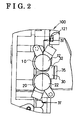
- a plate 120 is fixed to the timing chain cover 100 by means of a fixing member 121 (shown in Fig.2) in a manner where a gasket 110 is sandwiched between the plate 120 and the timing chain cover 100. Further, a groove 51 is formed on the plate 120, and an opening of the groove 51 is sealed by means of the gasket 110 so as to form a fluid path 50.
- a groove 61a formed on the timing chain cover 100 is sealed by means of the gasket 110 so as to form the fluid path 61
- a groove 62a formed on the gasket 110 is sealed by means of the gasket 110 so as to form the fluid path 62.
- a groove 71 a formed on the timing chain cover 100 is sealed by means of the gasket 110 so as to form the fluid path 71
- a groove 72a formed on the gasket 110 is sealed by means of the gasket 110 so as to form the fluid path 72.
- the first electromagnetic valve 10 includes a spool 11 serving as a first valve unit, a first valve unit housing space 14 for housing the spool 11, a sleeve 12 serving as a first housing portion and forming the first valve unit housing space 14, and a solenoid 13 for actuating the spool 11.
- the second electromagnetic valve 20 includes a spool 21 serving as a second valve unit, a second valve unit housing space 24 for housing the spool 21, a sleeve 22 serving as a second housing portion and forming the second valve unit housing space 24, and a solenoid 23 for actuating the spool 21.
- the spool 11 is movably housed in the sleeve 12, and the spool 21 is movably housed in the sleeve 22.
- the first housing portion may be integrated with the second housing portion.
- the oil filter 30 is comprised of a filtering member 31, a space within a cylinder 32a serving as a housing space in which the filtering member 31 is housed, and a case portion 32 forming the housing space. On one end of the case portion 32, a plug 35 is fit so as to fix the filtering member 31 in the case portion 32.
- the filtering member 31 is formed in a cylinder shape having a bottom portion 31b. An opening end portion 31a of the filtering member 31 is positioned within the through hole 111 formed on the gasket 110 so as to be fixed thereto. A bottom portion 31b contacts with the plug 35 so as to be fixed.
- the cylinder portion 31c of the filtering member 31 is formed in a mesh-type shape.
- the space within a cylinder 32a is formed so as to penetrate through the case portion 32, and one end of the space within a cylinder 32a is closed by means of a plug 35, which is fit to the case portion 32.
- the filtering member 31 housed in the space within a cylinder 32a can be replaced after removing the plug 35 from the case portion 32.
- the filtering member can be easily replaced; as a result maintenance efficiency has been impaired.
- the first housing portion may be integrated with the second housing portion. Thus, the number of parts can be decreased, and the electromagnetic valve unit can be downsized.
- an advanced angle supply port 12a and a retarded angle supply port 12b are formed on the upper side of the sleeve 12 of the first electromagnetic valve 10.
- the advanced angle supply port 12a opens to the fluid path 61, which is connected to the advanced angle chamber
- the retarded angle supply port 12b opens to fluid path 62, witch is connected to the retarded angle chamber.
- an advanced angle drain port 12c and a retarded angle drain port 12d are formed on the lower side of the sleeve 12.
- the hydraulic oil drains from the advanced angle chamber, through the fluid path 61, to the advanced angle drain port 12c, and the hydraulic oil drains from the retarded angle chamber, through the fluid path 62, to the retarded angle drain port 12d.
- an advanced angle supply port 22a and a retarded angle supply port 22b are formed on the lower side of the sleeve 22 of the second electromagnetic valve 20, on the lower side of the sleeve 22 of the second electromagnetic valve 20, an advanced angle supply port 22a and a retarded angle supply port 22b are formed. Specifically, the advanced angle supply port 22a opens to the fluid path 71, which is connected to the advanced angle chamber, and the retarded angle supply port 22b opens to fluid path 72, witch is connected to the retarded angle chamber.
- an advanced angle drain port 22c and a retarded angle drain port 22d are formed on the upper side of the sleeve 22. Specifically, the hydraulic oil drains from the advanced angle chamber, through the fluid path 71, to the advanced angle drain port 22c, and the hydraulic oil drains from the retarded angle chamber, through the fluid path 72, to the retarded angle drain port 22d.
- a first supply port 12e to which the hydraulic oil is supplied from the oil pump 40 through the fluid path 50.
- a second supply port 22e to which the hydraulic oil is supplied from the oil pump 40 through the fluid path 50, is formed.
- the space within a cylinder 32a is formed integrally with the first supply port 12e and the second supply portion 22e so as to form a space, which exist among the sleeve 12, the sleeve 22 and the case portion 32.
- the first supply port 12e and the second supply port 22e are formed by the space within a cylinder 32a. Because the space within a cylinder 32a, the first supply port 12e and the second supply port 22e are integrally formed, the space within a cylinder 32a can be directly connected to the first supply port 12e and the second supply port 22e. Thus, there is no need to form additional fluid paths between the space within a cylinder 32a and the supply port 12e, and between the space within a cylinder 32a and the supply port 22e, as a result, the electromagnetic valve unit can be downsized.
- the first valve unit housing space 14 is connected to the second valve unit housing space 24 by means of the first supply port 12e, the space within a cylinder 32a and the second supply port 22e.
- the first valve unit housing space 14, the second valve unit housing space 24, the first supply port 12e, the space within a cylinder 32a and the second supply port 22e are formed integrally with the sleeve 12, the sleeve 22 and the case portion 32, as a result, the electromagnetic valve unit can be downsized.
- a space S is formed between the sleeve 12 and the sleeve 22 when the electromagnetic valve 10 is provided next to the electromagnetic valve 20. Because the filter 30 is provided in the space S formed between the sleeve 12 and the sleeve 22, there is no need to provide an additional space for the filter 30, as a result, the timing chain cover 100, furthermore the engine can be downsized.
- timing chain cover 100 when the timing chain cover 100 is formed by die-cast, a portion of the timing chain cover 100, which corresponds to the space S, generally becomes thick, and such thick portion is intensively heated.
- the space within a cylinder 32a of the filter 30 is provided in the space S, casting porosities caused by such thickness and such intensive heat cannot be formed, or can be removed.
- the sleeve 12, the sleeve 22 and the case portion 32 are integrally formed so as to configure the housing 80 as a unit.
- An opening portion 60 connected to the oil pump 40 is formed on the housing 80, and the space within a cylinder 32a serving as the housing space for the filtering member 31 is connected to the opening portion 60.
- the first supply port 12e and the second supply port 22e are connected to the space within a cylinder 32a, the first supply port 12e and the second supply port 22e are connected to the opening portion 60 by means of the space within a cylinder 32a.
- the sleeves 12 and 22, the case portion 32 and the timing chain cover 100 are integrally formed.
- the number of parts, as an engine cover unit can be reduced.
- the opening portion 60, the space within a cylinder 32a, the first and the second supply ports 12e and 22e and the first and the second valve unit housing spaces 14 and 24 can be formed integrally with the housing, which is comprised of the timing chain cover 100. In this case, the costs for forming each space can be reduced as a whole.
- the hydraulic oil is selectively supplied to either one of the advanced angle chamber and the retarded angle chamber of the exhaust valve phase changing means.
- the opening/closing timings of the intake valve and the exhaust valve are preferably controlled.
- the electromagnetic valve 10 is positioned next to the electromagnetic valve 20, and the oil filter 30 is provided between the electromagnetic valve 10 and the electromagnetic valve 20, a length of the fluid path between the electromagnetic valve 10 and the intake valve phase changing means and a length of the fluid path between the electromagnetic valve 20 and the exhaust valve phase changing means can be shortened, as a result, the opening/closing timings of the intake valve and the exhaust valve can be rapidly changed.
- the filtering member 31 can be easily replaced, as a result, maintenance efficiency has been impaired.
- FIG.5 A second embodiment according to the present invention will be explained with reference to Fig.5.
- a sleeve 212 serving as a first housing portion and a sleeve 222 serving as a second housing portion are integrally formed so as to form a housing 280.
- the housing 280 is detachably fixed to the timing chain cover 200 by means of a fixing member (not shown), and this structure is different from the structure of the electromagnetic valve unit described in the first embodiment.
- the housing 280 forms a housing of the electromagnetic valve unit. Further, in the same manner as the electromagnetic valve unit described in the first embodiment, a first valve unit housing space 214, which houses a spool 211 serving as a first valve unit, is formed at the sleeve 212, and a second valve unit housing space 224, which houses a spool 221 serving as a second valve unit, is formed at the sleeve 222.
- a first supply portion 212e is formed at the sleeve 212, and a second supply port 222e is formed at the sleeve 222.
- An opening portion 260 is formed at the housing 280 so as to connect to the oil pump 40, and a housing space 234 for housing a filtering member 231 is formed at the housing 280 so as to connect to the opening portion 260.
- the opening portion 260 is formed by forming a recessed portion at the housing 280, and such recessed portion serves as the housing space 234 in which the filtering member 231 is housed. Further, the recessed portion includes stepped portions 213 and 223 in order to regulate the position of the filtering member 231.
- an opening portion 200a is formed so as to connect to the oil pump 40 (not shown in Fig.5).
- the housing 280 contacts with the timing chain cover 200 in a manner where the opening portion 260 of the housing 280 is aligned with the opening portion 200a of the timing chain cover 200.
- a flange portion 200b is formed at the opening portion 200a so that the opening 200a becomes smaller than the opening portion 260, and thus, when the housing 280 contacts with the timing chain cover 200, the filtering member 231 is sandwiched between the flange portion 200b and the stepped portions 213 and 223, as a result, the filtering member 231 can be fixed within the housing space 234.
- a groove 251 formed on the plate 220 is sealed by means of the gasket 210 so as to form a fluid path 250, and the spool 211 is housed in the sleeve 212, and the spool 221 is housed in the sleeve 222 so as to be movable.
- each of the first supply port 212e and the second supply port 222e is connected to the opening portion 260 through the housing space 234, hydraulic oil can be respectively supplied to the first electromagnetic valve 210 and the second electromagnetic valve 220 from the first supply portion 212e and the second supply port 222d through the opening portion 260, which is formed on the housing 280 and connected to the oil pump 40.
- a process for forming the fluid path can be simplified.
- only one opening such as the opening portion 200a, which corresponds to the opening portion 260 of the electromagnetic valve unit, needs to be formed, as a result, a process for forming the timing chain cover 200 can be simplified.
- the filtering member 231 can be easily replaced after removing the housing 280 from the timing chain cover 200.
- the present invention is not limited to only the electromagnetic valve units described in the first embodiment and the second embodiment.
- the valve opening/closing timing control device is explained as an example of the first and the second hydraulic mechanisms, however, another hydraulic mechanisms can be applied alternatively.
- the present invention can be preferably applied to the electromagnetic valve unit having plural electromagnetic valves for independently controlling the amount of the hydraulic oil supplied to plural hydraulic mechanisms.
- the present invention can also be preferably applied to an engine cover unit, in which an electromagnetic valve unit is formed integrally with such as an engine cover (e.g., a timing chain cover, a cylinder head cover and a cylinder head).
Landscapes
- Engineering & Computer Science (AREA)
- Mechanical Engineering (AREA)
- General Engineering & Computer Science (AREA)
- Chemical & Material Sciences (AREA)
- Combustion & Propulsion (AREA)
- Valve Device For Special Equipments (AREA)
Abstract
An electromagnetic valve unit comprises a first electromagnetic valve (10, 210) provided at a cover (100, 200), which is positioned at one end portion of an engine, for controlling an amount of hydraulic oil supplied from a hydraulic pressure source (40) to a first hydraulic mechanism, a second electromagnetic valve (20, 220) provided at the cover so as to be next to the first electromagnetic valve for controlling an amount of hydraulic oil supplied from the hydraulic pressure source to a second hydraulic mechanism, and an oil filter (30, 230) provided between the first electromagnetic valve and the second electromagnetic valve and connected to each of the first and the second electromagnetic valves in order to filter the hydraulic oil supplied to each of the first and the second electromagnetic valves.
Description
- This invention generally relates to an alignment structure for an electromagnetic valve. More particularly, this invention relates to an alignment for an electromagnetic valve in which at least two electromagnetic valves are aligned at a hydraulic circuit.
- A known alignment structure of an electromagnetic valve disclosed in, for example, JP2001-355415A, a variable valve timing control device (hereinafter referred to as a VVT) is mounted on each end of an intake camshaft and an exhaust camshaft in a cylinder head and each VVT is driven by a solenoid valve. Further, oil paths are connected to solenoid valves from a main fluid path through a common oil filter, the solenoid valves are respectively mounted outside of the cylinder head in the vicinity of the end portion of the corresponding camshaft.
- In such known alignment structure, because each of the VVT solenoid valves is positioned on each end of the cylinder head, a long fluid path needs to be formed, and this configuration requires a more space and increases costs of the electromagnetic valve. Further, because an oil filter for the solenoid valve is mounted within a cam chamber so as to be detachable, in each case the oil filter is removed, the head cover also needs to be removed, as a result, maintenance efficiency has been impaired.
- Thus, a need exists for the alignment structure of an electromagnetic valve to improve the alignment of the electromagnetic valves so that an electromagnetic valve unit becomes compact, and to improve the maintenance efficiency of the oil filter.
- According to an aspect of the present invention, an electromagnetic valve unit comprises a first electromagnetic valve (10, 210) provided at a cover (100, 200), which is positioned at one end portion of an engine, for controlling an amount of hydraulic oil supplied from a hydraulic pressure source (40) to a first hydraulic mechanism, a second electromagnetic valve (20, 220) provided at the cover so as to be next to the first electromagnetic valve for controlling an amount of hydraulic oil supplied from the hydraulic pressure source to a second hydraulic mechanism, and an oil filter (30, 230) provided between the first electromagnetic valve and the second electromagnetic valve and connected to each of the first and the second electromagnetic valves in order to filter the hydraulic oil supplied to each of the first and the second electromagnetic valves. The cover provided at the end portion of the engine serves as at least one portion of an engine case. Specifically, a timing chain cover, a cylinder head cover and a cylinder head can be presented as examples of such cover (hereinafter referred to as an engine cover type). Thus, the engine cover unit according to the present invention includes the engine cover type to which an electromagnetic valve unit and an oil filter are fixed.
- Each of the electromagnetic valves and the oil filter are provided at the cover, which is positioned at one end portion of the engine, and each of the electromagnetic valves are positioned so as to be next together, at the same time, the oil filter is provided between the electromagnetic valves. In this configuration, there is no need to provide an additional fluid path between the oil filter and each of the electromagnetic valves, as a result, a space for housing the electromagnetic valves and the oil filter can be saved. Further, because the oil filter is positioned at the cover, which is provided at one end of the engine, a process for replacing the oil filter can be simplified.
- According to another aspect of the present invention, an engine cover unit comprises a cover (100, 200) provided at an end portion of an engine, a first electromagnetic valve (10, 210) provided at the cover for controlling an amount of hydraulic oil supplied from a hydraulic pressure source (40) to a first hydraulic mechanism, a second electromagnetic valve (20, 220) provided next to the first electromagnetic valve for controlling an amount of hydraulic oil supplied from the hydraulic pressure source to a second hydraulic mechanism, and an oil filter (30, 230) provided between the first electromagnetic valve and the second electromagnetic valve and connected to each of the first and the second electromagnetic valves in order to filter the hydraulic oil supplied to each of the first and the second electromagnetic valves.
- Thus, each of the electromagnetic valves and the oil filter are provided at the cover, which is positioned at one end portion of the engine, and each of the electromagnetic valves are positioned so as to be next together, at the same time, the oil filter is provided between the electromagnetic valves. In this configuration, there is no need to provide an additional fluid path between the oil filter and each of the electromagnetic valves, as a result, a space for housing the electromagnetic valves and the oil filter can be saved. Further, because the oil filter is positioned at the cover, which is provided at one end of the engine, a process for replacing the oil filter can be simplified. Further, even when two electromagnetic valves are provided, only one fluid path needs to be formed, as a result, a process for forming the fluid path can be simplified.
- The foregoing and additional features and characteristics of the present invention will become more apparent from the following detailed description considered with reference to the accompanying drawings, wherein:
- Fig.1 illustrates a front view indicating a
timing chain cover 100 according to a first embodiment of the present invention; - Fig.2 illustrates a left side view of the
timing chain cover 100 shown in Fig.1; - Fig.3 illustrates a cross section along a III-III line in Fig.1;
- Fig.4 illustrates a cross section along a IV - IV line in Fig.2;
- Fig.5 illustrates a cross section of an essential part indicating a
timing chain cover 200 according to a second embodiment of the present invention. - Embodiments of the present invention will be explained with reference to drawing figures. A first embodiment of the present invention is shown in Figs.1, 2, 3 and 4. Figs 1 and 2 illustrate a timing chain cover 100 (cover), and the
timing chain cover 100 includes a firstelectromagnetic valve 10 and a secondelectromagnetic valve 20. Specifically, the firstelectromagnetic valve 10 controls hydraulic oil supplied to an intake valve phase changing means (intake valve opening/closing timing control device serving as a first hydraulic mechanism), which changes a rotation phase of an intake valve camshaft (not shown), and the secondelectromagnetic valve 20 controls hydraulic oil supplied to an exhaust valve phase changing means (exhaust valve opening/closing timing control device serving as a second hydraulic mechanism), which changes a rotation phase of an exhaust valve camshaft (not shown). - The intake valve phase changing means is comprised of a driven rotor, which is rotatably fixed to the intake valve camshaft so as to be integrated therewith, and a driving rotor, which is positioned rotatable relative to the driven rotor, and the exhaust valve phase changing means is comprised of a driven rotor, which is rotatably fixed to the exhaust valve camshaft so as to be integrated therewith, and a driving rotor, which is positioned rotatable relative to the driven rotor.
- By use of the intake valve phase changing means and the exhaust valve phase changing means, the hydraulic oil supplied to an advanced angle chamber and a retarded angle chamber, which are formed between the driven rotor and the driving rotor, is controlled in order to rotate the driven rotor relative to the driving rotor in an advanced angle side or a retarded angle side.
- The
timing chain cover 100 further includes anoil filter 30, which is provided between the firstelectromagnetic valve 10 and the secondelectromagnetic valve 20 so as to connect the firstelectromagnetic valve 10 to the secondelectromagnetic valve 20 in order to filter the hydraulic oil supplied to the firstelectromagnetic valve 10 and the secondelectromagnetic valve 20. An electromagnetic valve unit according to the present invention is comprised of the firstelectromagnetic valve 10, the secondelectromagnetic valve 20 and theoil filter 30, and an engine cover unit according to the present invention is comprised of the electromagnetic valve unit and thetiming chain cover 100. - Further, the
timing chain cover 100 includes anoil pump 40 serving as a hydraulic pressure source. Theoil pump 40 is actuated by acrank shaft 110. Afluid path 50 is formed between a discharge portion (not shown) of theoil pump 40 and theoil filter 30. On thetiming chain cover 100,fluid paths - Specifically, the
fluid path 61 is formed between the firstelectromagnetic valve 10 and the advanced angle chamber of the intake valve phase changing means, and thefluid path 62 is formed between the firstelectromagnetic valve 10 and the retarded angle chamber of the intake valve phase changing means. Thefluid path 71 is formed between the secondelectromagnetic valve 20 and the advanced angle chamber of the exhaust valve phase changing means, and thefluid path 72 is formed between the secondelectromagnetic valve 20 and the retarded angle chamber of the exhaust valve phase changing means. - As shown in Fig.3, a
plate 120 is fixed to thetiming chain cover 100 by means of a fixing member 121 (shown in Fig.2) in a manner where agasket 110 is sandwiched between theplate 120 and thetiming chain cover 100. Further, agroove 51 is formed on theplate 120, and an opening of thegroove 51 is sealed by means of thegasket 110 so as to form afluid path 50. - Similarly, a
groove 61a formed on thetiming chain cover 100 is sealed by means of thegasket 110 so as to form thefluid path 61, and agroove 62a formed on thegasket 110 is sealed by means of thegasket 110 so as to form thefluid path 62. - Further, a
groove 71 a formed on thetiming chain cover 100 is sealed by means of thegasket 110 so as to form thefluid path 71, and agroove 72a formed on thegasket 110 is sealed by means of thegasket 110 so as to form thefluid path 72. - As shown in Figs.3 and 4, the first
electromagnetic valve 10 includes aspool 11 serving as a first valve unit, a first valveunit housing space 14 for housing thespool 11, asleeve 12 serving as a first housing portion and forming the first valveunit housing space 14, and asolenoid 13 for actuating thespool 11. The secondelectromagnetic valve 20 includes aspool 21 serving as a second valve unit, a second valveunit housing space 24 for housing thespool 21, asleeve 22 serving as a second housing portion and forming the second valveunit housing space 24, and asolenoid 23 for actuating thespool 21. Thespool 11 is movably housed in thesleeve 12, and thespool 21 is movably housed in thesleeve 22. In this embodiment, the first housing portion may be integrated with the second housing portion. Thus, the number of parts can be decreased, and the electromagnetic valve unit can be downsized. - The
oil filter 30 is comprised of a filteringmember 31, a space within acylinder 32a serving as a housing space in which the filteringmember 31 is housed, and acase portion 32 forming the housing space. On one end of thecase portion 32, aplug 35 is fit so as to fix the filteringmember 31 in thecase portion 32. The filteringmember 31 is formed in a cylinder shape having abottom portion 31b. Anopening end portion 31a of the filteringmember 31 is positioned within the throughhole 111 formed on thegasket 110 so as to be fixed thereto. Abottom portion 31b contacts with theplug 35 so as to be fixed. - The
cylinder portion 31c of the filteringmember 31 is formed in a mesh-type shape. The space within acylinder 32a is formed so as to penetrate through thecase portion 32, and one end of the space within acylinder 32a is closed by means of aplug 35, which is fit to thecase portion 32. In this configuration, thefiltering member 31 housed in the space within acylinder 32a can be replaced after removing theplug 35 from thecase portion 32. Thus, the filtering member can be easily replaced; as a result maintenance efficiency has been impaired. Further, in this embodiment, the first housing portion may be integrated with the second housing portion. Thus, the number of parts can be decreased, and the electromagnetic valve unit can be downsized. - As shown in Fig.4, on the upper side of the
sleeve 12 of the firstelectromagnetic valve 10, an advancedangle supply port 12a and a retardedangle supply port 12b are formed. Specifically, the advancedangle supply port 12a opens to thefluid path 61, which is connected to the advanced angle chamber, and the retardedangle supply port 12b opens tofluid path 62, witch is connected to the retarded angle chamber. On the lower side of thesleeve 12, an advancedangle drain port 12c and a retardedangle drain port 12d are formed. Specifically, the hydraulic oil drains from the advanced angle chamber, through thefluid path 61, to the advancedangle drain port 12c, and the hydraulic oil drains from the retarded angle chamber, through thefluid path 62, to the retardedangle drain port 12d. - On the other hand, on the lower side of the
sleeve 22 of the secondelectromagnetic valve 20, an advancedangle supply port 22a and a retarded angle supply port 22b are formed. Specifically, the advancedangle supply port 22a opens to thefluid path 71, which is connected to the advanced angle chamber, and the retarded angle supply port 22b opens tofluid path 72, witch is connected to the retarded angle chamber. On the upper side of thesleeve 22, an advancedangle drain port 22c and a retardedangle drain port 22d are formed. Specifically, the hydraulic oil drains from the advanced angle chamber, through thefluid path 71, to the advancedangle drain port 22c, and the hydraulic oil drains from the retarded angle chamber, through thefluid path 72, to the retardedangle drain port 22d. - Between the
drain port 12c and thedrain port 12d of the firstelectromagnetic valve 10, afirst supply port 12e, to which the hydraulic oil is supplied from theoil pump 40 through thefluid path 50, is formed. On the other hand, between thedrain port 22c and thedrain port 22d of the secondelectromagnetic valve 20, asecond supply port 22e, to which the hydraulic oil is supplied from theoil pump 40 through thefluid path 50, is formed. - The space within a
cylinder 32a is formed integrally with thefirst supply port 12e and thesecond supply portion 22e so as to form a space, which exist among thesleeve 12, thesleeve 22 and thecase portion 32. In other words, thefirst supply port 12e and thesecond supply port 22e are formed by the space within acylinder 32a. Because the space within acylinder 32a, thefirst supply port 12e and thesecond supply port 22e are integrally formed, the space within acylinder 32a can be directly connected to thefirst supply port 12e and thesecond supply port 22e. Thus, there is no need to form additional fluid paths between the space within acylinder 32a and thesupply port 12e, and between the space within acylinder 32a and thesupply port 22e, as a result, the electromagnetic valve unit can be downsized. - Further, in the first embodiment, the first valve
unit housing space 14 is connected to the second valveunit housing space 24 by means of thefirst supply port 12e, the space within acylinder 32a and thesecond supply port 22e. - In this circumstances, the first valve
unit housing space 14, the second valveunit housing space 24, thefirst supply port 12e, the space within acylinder 32a and thesecond supply port 22e are formed integrally with thesleeve 12, thesleeve 22 and thecase portion 32, as a result, the electromagnetic valve unit can be downsized. - As shown in Fig.4, because a diameter of each of the
solenoid 13 and thesolenoid 23, which is comprised of a coil portion to which a coil is wound, is larger than a diameter of each of thesleeve 12 and thesleeve 22, a space S is formed between thesleeve 12 and thesleeve 22 when theelectromagnetic valve 10 is provided next to theelectromagnetic valve 20. Because thefilter 30 is provided in the space S formed between thesleeve 12 and thesleeve 22, there is no need to provide an additional space for thefilter 30, as a result, thetiming chain cover 100, furthermore the engine can be downsized. - Further, when the
timing chain cover 100 is formed by die-cast, a portion of thetiming chain cover 100, which corresponds to the space S, generally becomes thick, and such thick portion is intensively heated. However, in this embodiment, because the space within acylinder 32a of thefilter 30 is provided in the space S, casting porosities caused by such thickness and such intensive heat cannot be formed, or can be removed. - Furthermore, as shown in Fig.3, the
sleeve 12, thesleeve 22 and thecase portion 32 are integrally formed so as to configure thehousing 80 as a unit. An openingportion 60 connected to theoil pump 40 is formed on thehousing 80, and the space within acylinder 32a serving as the housing space for the filteringmember 31 is connected to the openingportion 60. Further, because thefirst supply port 12e and thesecond supply port 22e are connected to the space within acylinder 32a, thefirst supply port 12e and thesecond supply port 22e are connected to the openingportion 60 by means of the space within acylinder 32a. - In this circumstances, when the opening
portion 60 formed at thehousing 80 is connected to theoil pump 40, the hydraulic oil is supplied from thefirst supply port 12e to the firstelectromagnetic valve 10, and the hydraulic oil is supplied from thesecond supply port 22e to the secondelectromagnetic valve 20. - Thus, even when two electromagnetic valves are provided, there is no need to form two fluid paths between the
oil pump 40 and the openingportion 60, and only one fluid path is formed between theoil pump 40 and the openingportion 60, as a result, a process for forming the fluid path can be simplified. - Further, in this embodiment, as shown in Fig.3, the
sleeves case portion 32 and thetiming chain cover 100 are integrally formed. Thus, the number of parts, as an engine cover unit, can be reduced. Further, the openingportion 60, the space within acylinder 32a, the first and thesecond supply ports unit housing spaces timing chain cover 100. In this case, the costs for forming each space can be reduced as a whole. - Next, an actuation of the first embodiment will be explained. After the engine is started, and when opening/closing timings of the intake valve and the exhaust valve need to be changed depending on an engine rotation number and an engine load, rotation phases of the intake valve camshaft and the exhaust valve camshaft are changed. When the rotation phases of the intake valve camshaft and the exhaust valve camshaft are changed, the hydraulic oil is supplied to the first
electromagnetic valve 10 and the secondelectromagnetic valve 20 from theoil pump 40 through thefluid path 50. By an actuation of the firstelectromagnetic valve 10, the hydraulic oil is selectively supplied to either one of the advanced angle chamber and the retarded angle chamber of the intake valve phase changing means. On the other hand, by an actuation of the secondelectromagnetic valve 20, the hydraulic oil is selectively supplied to either one of the advanced angle chamber and the retarded angle chamber of the exhaust valve phase changing means. Thus, the opening/closing timings of the intake valve and the exhaust valve are preferably controlled. In this circumstance, because theelectromagnetic valve 10 is positioned next to theelectromagnetic valve 20, and theoil filter 30 is provided between theelectromagnetic valve 10 and theelectromagnetic valve 20, a length of the fluid path between theelectromagnetic valve 10 and the intake valve phase changing means and a length of the fluid path between theelectromagnetic valve 20 and the exhaust valve phase changing means can be shortened, as a result, the opening/closing timings of the intake valve and the exhaust valve can be rapidly changed. - Further, because the
oil filter 30 is provided at thetiming chain cover 100, the filteringmember 31 can be easily replaced, as a result, maintenance efficiency has been impaired. - A second embodiment according to the present invention will be explained with reference to Fig.5. As shown in Fig.5, a
sleeve 212 serving as a first housing portion and asleeve 222 serving as a second housing portion are integrally formed so as to form ahousing 280. Thehousing 280 is detachably fixed to thetiming chain cover 200 by means of a fixing member (not shown), and this structure is different from the structure of the electromagnetic valve unit described in the first embodiment. - Specifically, in the second embodiment, the
housing 280 forms a housing of the electromagnetic valve unit. Further, In the same manner as the electromagnetic valve unit described in the first embodiment, a first valveunit housing space 214, which houses aspool 211 serving as a first valve unit, is formed at thesleeve 212, and a second valveunit housing space 224, which houses aspool 221 serving as a second valve unit, is formed at thesleeve 222. - A
first supply portion 212e is formed at thesleeve 212, and asecond supply port 222e is formed at thesleeve 222. Anopening portion 260 is formed at thehousing 280 so as to connect to theoil pump 40, and ahousing space 234 for housing afiltering member 231 is formed at thehousing 280 so as to connect to theopening portion 260. Specifically, theopening portion 260 is formed by forming a recessed portion at thehousing 280, and such recessed portion serves as thehousing space 234 in which thefiltering member 231 is housed. Further, the recessed portion includes steppedportions filtering member 231. On the other hand, at thetiming chain cover 200, anopening portion 200a is formed so as to connect to the oil pump 40 (not shown in Fig.5). Thehousing 280 contacts with thetiming chain cover 200 in a manner where theopening portion 260 of thehousing 280 is aligned with theopening portion 200a of thetiming chain cover 200. In addition, aflange portion 200b is formed at theopening portion 200a so that theopening 200a becomes smaller than the openingportion 260, and thus, when thehousing 280 contacts with thetiming chain cover 200, the filteringmember 231 is sandwiched between theflange portion 200b and the steppedportions member 231 can be fixed within thehousing space 234. Agroove 251 formed on theplate 220 is sealed by means of thegasket 210 so as to form afluid path 250, and thespool 211 is housed in thesleeve 212, and thespool 221 is housed in thesleeve 222 so as to be movable. - In this configuration, in the same manner as the first embodiment, because each of the
first supply port 212e and thesecond supply port 222e is connected to theopening portion 260 through thehousing space 234, hydraulic oil can be respectively supplied to the firstelectromagnetic valve 210 and the secondelectromagnetic valve 220 from thefirst supply portion 212e and the second supply port 222d through theopening portion 260, which is formed on thehousing 280 and connected to theoil pump 40. Thus, even when two electromagnetic valves are provided, there is no need to form two fluid paths between theoil pump 40 and theopening portion 260, as a result, a process for forming the fluid path can be simplified. Further, only one opening such as theopening portion 200a, which corresponds to theopening portion 260 of the electromagnetic valve unit, needs to be formed, as a result, a process for forming thetiming chain cover 200 can be simplified. - Further, because the
housing 280 is detachably fixed to thetiming chain cover 200, and thefiltering member 231 is positioned between thehousing 280 and thetiming chain cover 200, the filteringmember 231 can be easily replaced after removing thehousing 280 from thetiming chain cover 200. - The present invention is not limited to only the electromagnetic valve units described in the first embodiment and the second embodiment. For example in the embodiments, the valve opening/closing timing control device is explained as an example of the first and the second hydraulic mechanisms, however, another hydraulic mechanisms can be applied alternatively. Thus, the present invention can be preferably applied to the electromagnetic valve unit having plural electromagnetic valves for independently controlling the amount of the hydraulic oil supplied to plural hydraulic mechanisms. And the present invention can also be preferably applied to an engine cover unit, in which an electromagnetic valve unit is formed integrally with such as an engine cover (e.g., a timing chain cover, a cylinder head cover and a cylinder head).
- It is explicitly stated that all features disclosed in the description and/or the claims are intended to be disclosed separately and independently from each other for the purpose of original disclosure as well as for the purpose of restricting the claimed invention independent of the composition of the features in the embodiments and/or the claims. It is explicitly stated that all value ranges or indications of groups of entities disclose every possible intermediate value or intermediate entity for the purpose of original disclosure as well as for the purpose of restricting the claimed invention, in particular as limits of value ranges.
Claims (10)
- An electromagnetic valve unit comprising:a first electromagnetic valve (10, 210) provided at a cover (100, 200), which is positioned at one end portion of an engine, for controlling an amount of hydraulic oil supplied from a hydraulic pressure source (40) to a first hydraulic mechanism;a second electromagnetic valve (20, 220) provided at the cover so as to be next to the first electromagnetic valve for controlling an amount of hydraulic oil supplied from the hydraulic pressure source to a second hydraulic mechanism; andan oil filter (30, 230) provided between the first electromagnetic valve and the second electromagnetic valve and connected to each of the first and the second electromagnetic valves in order to filter the hydraulic oil supplied to each of the first and the second electromagnetic valves.
- The electromagnetic valve unit according to Claim 1, wherein the first electromagnetic valve includes a first valve unit (11, 211) and a first housing portion (12, 212) in which the first valve unit is housed, the second electromagnetic valve includes a second valve unit (21, 221) and a second housing portion (22, 222) in which the second valve unit is housed, the oil filter includes a filtering member (31, 231) and a case portion (32) in which the filtering member is housed, and the first housing portion is connected to the second housing portion by means of the case portion.
- The electromagnetic valve unit according to Claim 2, wherein the first housing portion includes a first supply port (12e) to which the hydraulic oil is supplied from the hydraulic pressure source, the second housing portion includes a second supply port (22e) to which the hydraulic oil is supplied from the hydraulic pressure source, the case portion includes a housing space (32a) in which the filtering member is housed, and the first and the second supply ports and the housing space is integrally formed.
- The electromagnetic valve unit according to Claim 3, wherein a first valve unit housing space (14) for housing the first valve unit is formed at the first housing portion, a second valve unit housing space (24) for housing the second valve unit is formed at the second housing portion, and the first valve unit housing space is connected to the second valve unit housing space by means of the first supply port, the housing space, and the second supply port.
- The electromagnetic valve unit according to Claim 2, 3 or 4, wherein the first housing portion, the second housing portion and the case portion are integrally formed so as to form a housing (80) as a unit.
- The electromagnetic valve unit according to Claim 5, wherein an opening portion (60) connected to the hydraulic pressure source is formed at the housing, the housing space is connected to the opening portion, and the each of the first and the second supply port is connected to the opening portion through the housing space.
- An engine cover unit comprising:a cover (100, 200) provided at an end portion of an engine;a first electromagnetic valve (10, 210) provided at the cover for controlling an amount of hydraulic oil supplied from a hydraulic pressure source (40) to a first hydraulic mechanism;a second electromagnetic valve (20, 220) provided next to the first electromagnetic valve for controlling an amount of hydraulic oil supplied from the hydraulic pressure source to a second hydraulic mechanism; andan oil filter (30, 230) provided between the first electromagnetic valve and the second electromagnetic valve and connected to each of the first and the second electromagnetic valves in order to filter the hydraulic oil supplied to each of the first and the second electromagnetic valves.
- The engine cover unit according to Claim 7, wherein the first electromagnetic valve includes a first valve unit and a first housing portion in which the first valve unit is housed, the second electromagnetic valve includes a second valve unit and a second housing portion in which the second valve unit is housed, the oil filter includes a filtering member and a case portion in which the filtering member is housed, and the first housing portion is connected to the second housing portion by means of the case portion.
- The engine cover unit according to Claim 8, wherein the first housing portion includes a first supply port to which the hydraulic oil is supplied from the hydraulic pressure source, the second housing portion includes a second supply port to which the hydraulic oil is supplied from the hydraulic pressure source, the case portion includes a housing space in which the filtering member is housed, and the first and the second supply ports and the housing space is integrally formed.
- The engine cover unit according to Claim 7, 8 or 9, wherein the first housing portion, the second housing portion and the case portion are integrally formed so as to form a housing as a unit.
Applications Claiming Priority (2)
| Application Number | Priority Date | Filing Date | Title |
|---|---|---|---|
| JP2004279928 | 2004-09-27 | ||
| JP2005262020A JP4613760B2 (en) | 2004-09-27 | 2005-09-09 | Solenoid valve unit, engine cover unit |
Publications (1)
| Publication Number | Publication Date |
|---|---|
| EP1640570A1 true EP1640570A1 (en) | 2006-03-29 |
Family
ID=35455914
Family Applications (1)
| Application Number | Title | Priority Date | Filing Date |
|---|---|---|---|
| EP05020470A Withdrawn EP1640570A1 (en) | 2004-09-27 | 2005-09-20 | Electromagnetic valve unit and engine cover unit |
Country Status (3)
| Country | Link |
|---|---|
| US (1) | US20060065581A1 (en) |
| EP (1) | EP1640570A1 (en) |
| JP (1) | JP4613760B2 (en) |
Families Citing this family (5)
| Publication number | Priority date | Publication date | Assignee | Title |
|---|---|---|---|---|
| JP5546388B2 (en) * | 2010-08-25 | 2014-07-09 | 本田技研工業株式会社 | Control valve mounting structure of variable valve timing mechanism |
| JP2018184117A (en) * | 2017-04-27 | 2018-11-22 | スズキ株式会社 | Oil control valve unit installation structure and motorcycle |
| JP7739975B2 (en) | 2021-11-26 | 2025-09-17 | スズキ株式会社 | internal combustion engine |
| JP7726038B2 (en) | 2021-11-26 | 2025-08-20 | スズキ株式会社 | internal combustion engine |
| JP7740045B2 (en) * | 2022-02-10 | 2025-09-17 | スズキ株式会社 | variable valve timing system |
Citations (7)
| Publication number | Priority date | Publication date | Assignee | Title |
|---|---|---|---|---|
| US5718196A (en) * | 1994-09-30 | 1998-02-17 | Yamaha Hatsudoki Kabushiki Kaisha | Lubrication and camshaft control system for engine |
| US5954019A (en) * | 1996-12-26 | 1999-09-21 | Yamaha Hatsudoki Kabushiki Kaisha | Variable valve timing arrangement for engine |
| EP1046793A2 (en) * | 1999-04-21 | 2000-10-25 | Ford Global Technologies, Inc. | Variable cam timing system and method |
| EP1057982A2 (en) * | 1999-05-31 | 2000-12-06 | Yamaha Hatsudoki Kabushiki Kaisha | Four-stroke cycle engine |
| US6295964B1 (en) * | 2000-08-10 | 2001-10-02 | Ford Global Technologies, Inc. | End-feed variable cam timing oil supply and control module |
| JP2001355415A (en) * | 2000-06-13 | 2001-12-26 | Yamaha Motor Co Ltd | Arrangement structure of vvt solenoid valve |
| EP1316682A2 (en) * | 2001-11-30 | 2003-06-04 | Yamaha Hatsudoki Kabushiki Kaisha | Cylinder head for an internal combustion engine |
Family Cites Families (4)
| Publication number | Priority date | Publication date | Assignee | Title |
|---|---|---|---|---|
| JPH09317412A (en) * | 1996-05-24 | 1997-12-09 | Toyota Motor Corp | Valve opening / closing characteristic control device for internal combustion engine |
| JP3444467B2 (en) * | 1996-12-26 | 2003-09-08 | ヤマハ発動機株式会社 | Return oil scattering prevention structure for 4-cycle engine |
| JPH11303615A (en) * | 1998-04-24 | 1999-11-02 | Yamaha Motor Co Ltd | Engine with variable valve timing device |
| JP4517514B2 (en) * | 2001-02-14 | 2010-08-04 | マツダ株式会社 | Oiling device for variable valve timing mechanism of internal combustion engine |
-
2005
- 2005-09-09 JP JP2005262020A patent/JP4613760B2/en not_active Expired - Fee Related
- 2005-09-20 EP EP05020470A patent/EP1640570A1/en not_active Withdrawn
- 2005-09-26 US US11/234,244 patent/US20060065581A1/en not_active Abandoned
Patent Citations (7)
| Publication number | Priority date | Publication date | Assignee | Title |
|---|---|---|---|---|
| US5718196A (en) * | 1994-09-30 | 1998-02-17 | Yamaha Hatsudoki Kabushiki Kaisha | Lubrication and camshaft control system for engine |
| US5954019A (en) * | 1996-12-26 | 1999-09-21 | Yamaha Hatsudoki Kabushiki Kaisha | Variable valve timing arrangement for engine |
| EP1046793A2 (en) * | 1999-04-21 | 2000-10-25 | Ford Global Technologies, Inc. | Variable cam timing system and method |
| EP1057982A2 (en) * | 1999-05-31 | 2000-12-06 | Yamaha Hatsudoki Kabushiki Kaisha | Four-stroke cycle engine |
| JP2001355415A (en) * | 2000-06-13 | 2001-12-26 | Yamaha Motor Co Ltd | Arrangement structure of vvt solenoid valve |
| US6295964B1 (en) * | 2000-08-10 | 2001-10-02 | Ford Global Technologies, Inc. | End-feed variable cam timing oil supply and control module |
| EP1316682A2 (en) * | 2001-11-30 | 2003-06-04 | Yamaha Hatsudoki Kabushiki Kaisha | Cylinder head for an internal combustion engine |
Non-Patent Citations (1)
| Title |
|---|
| PATENT ABSTRACTS OF JAPAN vol. 2002, no. 04 4 August 2002 (2002-08-04) * |
Also Published As
| Publication number | Publication date |
|---|---|
| JP2006118497A (en) | 2006-05-11 |
| US20060065581A1 (en) | 2006-03-30 |
| JP4613760B2 (en) | 2011-01-19 |
Similar Documents
| Publication | Publication Date | Title |
|---|---|---|
| US7487752B2 (en) | Control valve for a device to modify the timing of an internal combustion engine | |
| US10344635B2 (en) | Hydraulic pressure control valve and internal-combustion engine valve timing control apparatus | |
| US20070119402A1 (en) | Variable phase drive coupling | |
| US20130220253A1 (en) | Cam torque actuated phaser with mid position lock | |
| KR20100126447A (en) | Variable camshaft timing device with hydraulic lock in the intermediate position | |
| JP2011256786A (en) | Flow rate control valve | |
| JP2003083464A (en) | solenoid valve | |
| US20090241878A1 (en) | Valve timing adjusting apparatus | |
| CN101113680A (en) | Variable valve system for internal combustion engines | |
| US20130233261A1 (en) | Valve timing control device of internal combustion engine | |
| EP1640570A1 (en) | Electromagnetic valve unit and engine cover unit | |
| JP2008523294A (en) | Control valve | |
| CN109209548B (en) | Variable camshaft timing device with two locking positions | |
| JP3912474B2 (en) | Oil passage structure | |
| JP5152312B2 (en) | Valve timing adjustment device | |
| JP4340908B2 (en) | Engine oil passage structure | |
| WO2015111482A1 (en) | Variable volume oil pump | |
| JP4736986B2 (en) | Valve timing control device | |
| JP4014025B2 (en) | Spool valve device | |
| KR100521176B1 (en) | responsibility improving apparatus of continuous variable valve timing actuator | |
| JP3780594B2 (en) | Valve timing control device for internal combustion engine | |
| JP2002242630A (en) | Variable valve train for internal combustion engines | |
| JP4109795B2 (en) | Valve operating characteristic variable device | |
| JP4922115B2 (en) | Solenoid valve mounting structure | |
| JP2012219744A (en) | Hydraulic control valve |
Legal Events
| Date | Code | Title | Description |
|---|---|---|---|
| PUAI | Public reference made under article 153(3) epc to a published international application that has entered the european phase |
Free format text: ORIGINAL CODE: 0009012 |
|
| AK | Designated contracting states |
Kind code of ref document: A1 Designated state(s): AT BE BG CH CY CZ DE DK EE ES FI FR GB GR HU IE IS IT LI LT LU LV MC NL PL PT RO SE SI SK TR |
|
| AX | Request for extension of the european patent |
Extension state: AL BA HR MK YU |
|
| AKX | Designation fees paid | ||
| STAA | Information on the status of an ep patent application or granted ep patent |
Free format text: STATUS: THE APPLICATION IS DEEMED TO BE WITHDRAWN |
|
| 18D | Application deemed to be withdrawn |
Effective date: 20060930 |
|
| REG | Reference to a national code |
Ref country code: DE Ref legal event code: 8566 |