EP1640289A1 - Drawer case - Google Patents
Drawer case Download PDFInfo
- Publication number
- EP1640289A1 EP1640289A1 EP04022623A EP04022623A EP1640289A1 EP 1640289 A1 EP1640289 A1 EP 1640289A1 EP 04022623 A EP04022623 A EP 04022623A EP 04022623 A EP04022623 A EP 04022623A EP 1640289 A1 EP1640289 A1 EP 1640289A1
- Authority
- EP
- European Patent Office
- Prior art keywords
- drawer
- case
- case body
- case according
- closure plate
- Prior art date
- Legal status (The legal status is an assumption and is not a legal conclusion. Google has not performed a legal analysis and makes no representation as to the accuracy of the status listed.)
- Withdrawn
Links
- 238000007789 sealing Methods 0.000 claims abstract description 27
- 239000002274 desiccant Substances 0.000 claims abstract description 21
- 239000000463 material Substances 0.000 claims description 6
- 239000004033 plastic Substances 0.000 claims description 4
- 239000004743 Polypropylene Substances 0.000 claims description 3
- -1 polypropylene Polymers 0.000 claims description 2
- 229920001155 polypropylene Polymers 0.000 claims description 2
- 238000004519 manufacturing process Methods 0.000 description 2
- 229920000642 polymer Polymers 0.000 description 2
- XAGFODPZIPBFFR-UHFFFAOYSA-N aluminium Chemical compound [Al] XAGFODPZIPBFFR-UHFFFAOYSA-N 0.000 description 1
- 229910052782 aluminium Inorganic materials 0.000 description 1
- 239000004411 aluminium Substances 0.000 description 1
- 238000011161 development Methods 0.000 description 1
- 230000018109 developmental process Effects 0.000 description 1
- 239000003814 drug Substances 0.000 description 1
- 229940079593 drug Drugs 0.000 description 1
- 230000000694 effects Effects 0.000 description 1
- 239000013013 elastic material Substances 0.000 description 1
- 238000001704 evaporation Methods 0.000 description 1
- 230000007774 longterm Effects 0.000 description 1
- 239000002245 particle Substances 0.000 description 1
- 238000000926 separation method Methods 0.000 description 1
- 239000000126 substance Substances 0.000 description 1
Images


Classifications
-
- B—PERFORMING OPERATIONS; TRANSPORTING
- B65—CONVEYING; PACKING; STORING; HANDLING THIN OR FILAMENTARY MATERIAL
- B65D—CONTAINERS FOR STORAGE OR TRANSPORT OF ARTICLES OR MATERIALS, e.g. BAGS, BARRELS, BOTTLES, BOXES, CANS, CARTONS, CRATES, DRUMS, JARS, TANKS, HOPPERS, FORWARDING CONTAINERS; ACCESSORIES, CLOSURES, OR FITTINGS THEREFOR; PACKAGING ELEMENTS; PACKAGES
- B65D81/00—Containers, packaging elements, or packages, for contents presenting particular transport or storage problems, or adapted to be used for non-packaging purposes after removal of contents
- B65D81/24—Adaptations for preventing deterioration or decay of contents; Applications to the container or packaging material of food preservatives, fungicides, pesticides or animal repellants
- B65D81/26—Adaptations for preventing deterioration or decay of contents; Applications to the container or packaging material of food preservatives, fungicides, pesticides or animal repellants with provision for draining away, or absorbing, or removing by ventilation, fluids, e.g. exuded by contents; Applications of corrosion inhibitors or desiccators
- B65D81/264—Adaptations for preventing deterioration or decay of contents; Applications to the container or packaging material of food preservatives, fungicides, pesticides or animal repellants with provision for draining away, or absorbing, or removing by ventilation, fluids, e.g. exuded by contents; Applications of corrosion inhibitors or desiccators for absorbing liquids
-
- B—PERFORMING OPERATIONS; TRANSPORTING
- B65—CONVEYING; PACKING; STORING; HANDLING THIN OR FILAMENTARY MATERIAL
- B65D—CONTAINERS FOR STORAGE OR TRANSPORT OF ARTICLES OR MATERIALS, e.g. BAGS, BARRELS, BOTTLES, BOXES, CANS, CARTONS, CRATES, DRUMS, JARS, TANKS, HOPPERS, FORWARDING CONTAINERS; ACCESSORIES, CLOSURES, OR FITTINGS THEREFOR; PACKAGING ELEMENTS; PACKAGES
- B65D11/00—Containers having bodies formed by interconnecting or uniting two or more rigid, or substantially rigid, components made wholly or mainly of plastics material
- B65D11/10—Containers having bodies formed by interconnecting or uniting two or more rigid, or substantially rigid, components made wholly or mainly of plastics material of polygonal cross-section and all parts being permanently connected to each other
- B65D11/12—Containers having bodies formed by interconnecting or uniting two or more rigid, or substantially rigid, components made wholly or mainly of plastics material of polygonal cross-section and all parts being permanently connected to each other of drawer-and-shell type
Definitions
- the present invention relates to a drawer case, preferably for breath strips, according to the opening portion of claim 1.
- a breath strip case is well known since the nineties.
- US patent 5,016,659 shows a container comprising a plurality of breath sticks
- US patent application 2004/0079665 shows a breath strip case which consists of a base, a cover and a lid.
- This case is intended to be air-tight, in order to prevent moisture from entering the case.
- Breath strips are widely promoted for on-hand-use on demand.
- pocket-safe boxes which are intended to keep the breath strip ready to use.
- Such boxes or cases must sufficiently protect the breath strip even if handling is rough.
- a drawer which is received in the case body and consists of or at least comprises desiccant.
- the side walls, the rear wall and the bottom wall of the drawer have desiccant such that the closure plate may be made from or contain a different material such as rubber.
- the closure plate may contain a different material such as rubber.
- the closure plate may be made from desiccant such that the drawer may be formed integrally in one piece.
- the desiccant keeps the goods or article contained in the inventive case dry over a long time. Even if the case is opened and re-closed the desiccant continues to keep the goods dry as it is selected to work on a long-term basis. Any desiccant, in particular any desiccant containing polymer composition may be used. Advantageously, the desiccant may not get lost and changed with the good as it is part of the container or case.
- an air-tight seal may be provided, and the sealing line is - with usual dimensions of drawers - about a third of the sealing line of the above-mentioned prior art document.
- the sealing may be improved by using a rubber closure plate or a sealing ring due to the elasticity exerting a slight pressure outwardly towards the inner edge of the case opening and thus sealing between the closure plate and the case opening.
- the drawer has a frictional or a snap lock in the container in the closed state.
- the drawer does not open unintentionally. Frictional engagement may be ensured by the above-mentioned sealing line between the closure plate and the inner edge of the case opening, using the resilient characteristic of the closure plate.
- a snap lock is provided, the same shoulder or recess or protrusion may be used both for closure snap lock and for separation snap lock, i.e. an additional snap lock which prevents the drawer from getting fully separated from the case body.
- any shoulders provided for the snap lock may be made in a rounded or convex arrangement, and also the case body may be produced in one piece and may be made from any suitable plastic, like polypropylene.
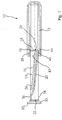
- Figure 1 shows an embodiment of the case 10 according to the invention which basically consists of a case body 12 and a drawer 14.
- the case body 12 has a longish form as it is usual for cases which are intended to receive drawers. It is made from PP while any other suitable materials might be used as well as long as it is are sufficiently moisture tight and not too expensive. Other examples are PE, PA or PU. It is also possible to provide an thin layer e.g. from aluminium or any other suitable substance on the inner side of the body in order to ensure the moisture tightness.
- the drawer 14 generally has the usual rectangular shape of a drawer. Thus, it has side walls 16, a rear wall and a bottom wall 20. In this example however, the bottom wall 20 is sloped from the front end 22 towards the rear end 24 of the drawer 14. By this, a breath strip 26 may easily be taken out even if it fully covers the bottom wall 20, just by drawing it towards front end, with a finger pressed on its upper surface.
- the drawer 14 consists of a desiccant-entrained composition such as those disclosed in US Patent Application Serial No. 10/328,579 or US 5,432,214 A1 in this embodiment.
- a desiccant-entrained composition such as those disclosed in US Patent Application Serial No. 10/328,579 or US 5,432,214 A1 in this embodiment.
- Any desiccant material e.g. one made from a polymer plastic material with desiccant particles being contained or entrained therein may be used.
- Other suitable desiccants may be used, and it is also possible to have a desiccant layer arranged on the inner side of the drawer 14.
- the drawer 14 is equipped with a special closure plate 30.
- the closure plate 30 is made from or contain rubber and is firmly attached to the remainder of the drawer 14. Its outer dimensions are such that they form a grip projection 32 at its top and bottom ends which overtop the respective parts of the case body 12 in the closed state of the drawer.
- the bottom wall is slanted, and, close to the front end 22, upwardly bend.
- the first lock consists of projections or shoulders 34 and 36 arrange facing upwardly and downwardly on the drawer, close to the front end 22, and corresponding projections or shoulders 38 and 40 arranged near an opening 42 of the case body 12 and facing towards the drawer 14.
- the shoulders 34 to 40 keep the drawer 14 sately in the closed state while it may be opened when manually drawing at grip projections 32.
- a further locking shoulder arrangement forming the second snap lock with locking shoulders 44 and 46 is arranged at the rear end 24 of the drawer 14, extending from rear wall 18. Contrary to the rounded protrusions 34 and 36, these shoulders 44 and 46 have sharp edges facing toward the front end 22 of the drawer 14 such that the force required to fully separate the drawer 14 from the case body 12 is considerably higher, e.g. three times higher than the force required to open the drawer.
- the stiffness of the case body 12 may be selected in a suitable manner.
- Figure 2 shows the embodiment according to figure 1 in the closed state. Same reference numerals correspond to same parts.
- the closure plate 30 is inserted into the opening 42 of the case body 12. It has a press-fit there allowing a sealing around a sealing line 50.
- this sealing line may also be provided with a very small ridge which is not shown in the figures 1 and 2.
- the sealing line 50 is also protected as it is arranged internally.
- Figure 3 shows that ribs 60 and 62 are provided extending in the moving direction of the drawer 14 near the lateral ends of the case body 12. These ribs are both for stiffening the case body and for design purposes.
- the grip projections 32 are provided in a central area of closure plate 30. It will be understood that it is possible to have them arranged in any other suitable manner.
- Figure 4 shows how the protrusion 40 extends nearly over the full width of case body 12.
- the protrusions 34 and 36 arranged on the drawer 14, on the other hand, may be provided only at the corresponding side wall 16.
- Figure 5 shows an alternative embodiment of the closure plate 30 for the drawer 14.
- a sealing ring 70 is provided on a horizontal portion 72 of the closure plate which is intended to be pressed agains the opening 42 of the case body 12.
- Figure 6 shows a different embodiment of the sealing means.
- a sealing layer 74 is provided both on the horizontal portion 72 and the oblique portion 76 of the closure plate.
- Both, the sealing 70 and the sealing layer 74 may be made from or contain rubber or similar elastic materials with sealing properties.
Landscapes
- Engineering & Computer Science (AREA)
- Mechanical Engineering (AREA)
- Food Science & Technology (AREA)
- Packages (AREA)
Abstract
The present invention relates to a case (10), preferably for breath strips (26), with a case body (12). The case body (12) receives and guides a drawer (14) which consists of desiccant or comprises desiccant, and that sealing means are provided for sealing the drawer (14) against the case body (12) in the closed state of the drawer (14).
Description
- The present invention relates to a drawer case, preferably for breath strips, according to the opening portion of claim 1.
- A breath strip case is well known since the nineties. For example, US patent 5,016,659 shows a container comprising a plurality of breath sticks, and US patent application 2004/0079665 shows a breath strip case which consists of a base, a cover and a lid. This case is intended to be air-tight, in order to prevent moisture from entering the case. Breath strips are widely promoted for on-hand-use on demand. There are usually kept in pocket-safe boxes which are intended to keep the breath strip ready to use. Such boxes or cases must sufficiently protect the breath strip even if handling is rough. On the other hand, they should incur only little manufacutring costs bearing in mind that they are sometimes used only once such that it is essential to keep the manufacturing costs within reasonable limits.
- On the other hand, small goods such as breath strips, electronic equipment, drugs etc. have to be kept dry. To this end, the above-mentioned US-A-2004/0079665 has an air-tight fit which allows the breath strip or similar good to be kept dry as long as the case is not opened.
- On the other hand, as soon as the case is opened, moisture from the environment will enter the case such that the air-tight fit is no longer effective. Even worse, if moisture, i.e. a rain drop, gets into the opened case, the air-tight fit will prevent the moisture from evaporating from the air-tight closed case.
- To overcome these disadvantages, it has been proposed to provide a desiccant within a case for receiving moisture-sensitive goods.
- Such a desiccant, however, adds to the manufacutring costs. Moreover, a firm attachment is required, in order to avoid that the user of the case unintentionally utilizes the desiccant instead of the good.
- An other problem of the known breath strip case is the relatively long sealing line. Due to its length which is about double the length plus double the width of the case, the sealing will not work if there is any deformation of the case which might be caused by mechanical or thermal load or natural deformation.
- In view of the above, it is an object of the present invention to provide a case according to the opening portion of claim 1 which incurs low manufacturing costs and is suitable to receive moisture-sensitive goods.
- This object is settled by claim 1. Advantageous developments may be taken from the subclaims.
- With the inventive case, a drawer is provided which is received in the case body and consists of or at least comprises desiccant. Usually, it is sufficient if the side walls, the rear wall and the bottom wall of the drawer have desiccant such that the closure plate may be made from or contain a different material such as rubber.
- Alternatively, the closure plate may contain a different material such as rubber.
- On the other hand, even the closure plate may be made from desiccant such that the drawer may be formed integrally in one piece. Surprisingly, by this simple step to select a desiccant disclosed in United States Patent Application Serial No. 10/328,579 or US 5,432,214 A1 for the drawer, several advantages are obtained:
- The desiccant keeps the goods or article contained in the inventive case dry over a long time. Even if the case is opened and re-closed the desiccant continues to keep the goods dry as it is selected to work on a long-term basis. Any desiccant, in particular any desiccant containing polymer composition may be used. Advantageously, the desiccant may not get lost and changed with the good as it is part of the container or case.
- By closing the case with the closure plate, an air-tight seal may be provided, and the sealing line is - with usual dimensions of drawers - about a third of the sealing line of the above-mentioned prior art document.
- The sealing may be improved by using a rubber closure plate or a sealing ring due to the elasticity exerting a slight pressure outwardly towards the inner edge of the case opening and thus sealing between the closure plate and the case opening.
- Advantageously, the drawer has a frictional or a snap lock in the container in the closed state. By this, the drawer does not open unintentionally. Frictional engagement may be ensured by the above-mentioned sealing line between the closure plate and the inner edge of the case opening, using the resilient characteristic of the closure plate. If a snap lock is provided, the same shoulder or recess or protrusion may be used both for closure snap lock and for separation snap lock, i.e. an additional snap lock which prevents the drawer from getting fully separated from the case body.
- Any shoulders provided for the snap lock may be made in a rounded or convex arrangement, and also the case body may be produced in one piece and may be made from any suitable plastic, like polypropylene.
- Further advantages, details and features may be taken from the following description of the invention with reference to the drawings.
- In the drawings:
- Figure 1
- shows a sectional view of one embodiment of the case according to the invention, with the drawer shown in an opening state;
- Figure 2
- shows the embodiment according to Figure 1 in a closed state;
- Figure 3
- shows a perspective view of an embodiment of the inventive case in an open state;
- Figure 4
- shows the inventive case body with the drawer taken out;
- Figure 5
- shows an alternative embodiment of the sealing of the drawer for a case accordings with the invention; and
- Figure 6
- shows a second alternative sealing for the drawer of the case according to the invention.
- Figure 1 shows an embodiment of the
case 10 according to the invention which basically consists of acase body 12 and adrawer 14. Thecase body 12 has a longish form as it is usual for cases which are intended to receive drawers. It is made from PP while any other suitable materials might be used as well as long as it is are sufficiently moisture tight and not too expensive. Other examples are PE, PA or PU. It is also possible to provide an thin layer e.g. from aluminium or any other suitable substance on the inner side of the body in order to ensure the moisture tightness. - The
drawer 14 generally has the usual rectangular shape of a drawer. Thus, it hasside walls 16, a rear wall and abottom wall 20. In this example however, thebottom wall 20 is sloped from thefront end 22 towards therear end 24 of thedrawer 14. By this, abreath strip 26 may easily be taken out even if it fully covers thebottom wall 20, just by drawing it towards front end, with a finger pressed on its upper surface. - According to the invention, the
drawer 14 consists of a desiccant-entrained composition such as those disclosed in US Patent Application Serial No. 10/328,579 or US 5,432,214 A1 in this embodiment. Any desiccant material, e.g. one made from a polymer plastic material with desiccant particles being contained or entrained therein may be used. Other suitable desiccants may be used, and it is also possible to have a desiccant layer arranged on the inner side of thedrawer 14. - In this embodiment, the
drawer 14 is equipped with aspecial closure plate 30. Theclosure plate 30 is made from or contain rubber and is firmly attached to the remainder of thedrawer 14. Its outer dimensions are such that they form agrip projection 32 at its top and bottom ends which overtop the respective parts of thecase body 12 in the closed state of the drawer. - Thus, a user may easily open the drawer.
- With the present embodiment, the bottom wall is slanted, and, close to the
front end 22, upwardly bend. By this measure, the volume to be received within the drawer is still increased. - In order to prevent the drawer to get separated from the
case body 12 and in order to stay in the closed state, two snap locks are provided. The first lock consists of projections orshoulders front end 22, and corresponding projections orshoulders opening 42 of thecase body 12 and facing towards thedrawer 14. Theshoulders 34 to 40 keep thedrawer 14 sately in the closed state while it may be opened when manually drawing atgrip projections 32. - A further locking shoulder arrangement forming the second snap lock with locking
shoulders rear end 24 of thedrawer 14, extending fromrear wall 18. Contrary to the roundedprotrusions shoulders front end 22 of thedrawer 14 such that the force required to fully separate thedrawer 14 from thecase body 12 is considerably higher, e.g. three times higher than the force required to open the drawer. - In this regard, the stiffness of the
case body 12 may be selected in a suitable manner. - Figure 2 shows the embodiment according to figure 1 in the closed state. Same reference numerals correspond to same parts. As may be taken from figure 2, the
closure plate 30 is inserted into theopening 42 of thecase body 12. It has a press-fit there allowing a sealing around a sealingline 50. Optionally, this sealing line may also be provided with a very small ridge which is not shown in the figures 1 and 2. - The sealing
line 50 is also protected as it is arranged internally. - As it is shown from figure 2, in the closed state, the
projections protrusions protrusions drawer 14 firmly in closed state. - Figure 3 shows that
ribs 60 and 62 are provided extending in the moving direction of thedrawer 14 near the lateral ends of thecase body 12. These ribs are both for stiffening the case body and for design purposes. - In this example, the
grip projections 32, are provided in a central area ofclosure plate 30. It will be understood that it is possible to have them arranged in any other suitable manner. - Figure 4 shows how the
protrusion 40 extends nearly over the full width ofcase body 12. Theprotrusions drawer 14, on the other hand, may be provided only at thecorresponding side wall 16. - Figure 5 shows an alternative embodiment of the
closure plate 30 for thedrawer 14. A sealingring 70 is provided on ahorizontal portion 72 of the closure plate which is intended to be pressed agains theopening 42 of thecase body 12. - Figure 6 shows a different embodiment of the sealing means. Instead of a sealing ring, a
sealing layer 74 is provided both on thehorizontal portion 72 and theoblique portion 76 of the closure plate. - Both, the sealing 70 and the
sealing layer 74 may be made from or contain rubber or similar elastic materials with sealing properties.
Claims (17)
- Case, preferably for breath strips, with a case body, characterized in that the case body (12) receives and guides a drawer (14) which consists of desiccant or comprises desiccant, and that sealing means are provided for sealing the drawer (14) against the case body (12) in the closed state of the drawer (14) .
- Case according to claim 1, characterized in that the drawer (14) has a closure plate (30) sealing against an opening (42) of the case body (12).
- Case according to claim 2, characterized in that the closure plate (30) partially extends into the case body (12) to provide a sealing surface extending substantially in the moving direction of the drawer (14) against the case body (12).
- Case according to one of the preceding claims, characterized in that the case body (12) comprises at least one protrusion (38, 40) at its inner side close to its opening (42), protruding towards the drawer (14).
- Case according to one of the preceding claims, characterized in that the drawer (14) has two protrusions (34, 36) which extend towards the case body (12).
- Case according to one of the preceding claims, characterized in that the case body (12) is yielding or pliable close to protrusions (38, 40) extending towards the drawer (14), in order to form a snap-in lock against the drawer (14).
- Case according to one of the preceding claims, characterized in that the drawer case has a first snap lock (34, 40) between the case body (12) and the drawer (14) which is active in the closed state of the drawer (14) and a second snap lock (44, 46) acting when separating of the drawer (14) from the case body (12).
- Case according to one of the preceding claims, characterized in that a first snap lock between the case body (12) and the drawer (14) comprises shoulders (34, 36, 38, 40) at the drawer (14) and the case body (12) acting against each other and forming a snap-in connection therebetween.
- Case according to claim 7, characterized in that said shoulders (34, 36) are formed as rounded ridges on surfaces of the drawer (14) and the case body (12) facing each other.
- Drawer case according to one of the preceding claims, characterized in that the drawer (14) has a bottom (20) extending upwardly slanted from its rear end (24) toward its front end (22).
- Case according to claim 9, characterized in that the drawer bottom (20) is upwardly curved near the front end (22) of the body (12).
- Case according to one of the preceding claims, characterized in that the drawer (14) has side walls (16) and a rear wall (18) extending basically over the full inner height of the case body (12).
- Case according to one of the preceding claims, characterized in that drawer (14) is made from a plastic desiccant, and that the case body (12) is made from a fluid-tight plastic material, preferably from polypropylene.
- Case according to one of the preceding claims, characterized in that a closure plate (30) fixed to the drawer (14) is made from rubber.
- Case according to one of the preceding claims, characterized in that a closure plate (30) of the drawer (14) has a grip projection (32) overtopping the case body (12).
- Drawer case according to one of the preceding claims, characterized in that it has suitable dimensions for breath strips (26).
- Drawer case according to one of the preceding claims, characterized in that the drawer (14) has an inner width of 20 to 30 mm, preferably about 23 mm and an overall length of 30 to 60 mm, preferably 45 mm.
Priority Applications (1)
| Application Number | Priority Date | Filing Date | Title |
|---|---|---|---|
| EP04022623A EP1640289A1 (en) | 2004-09-23 | 2004-09-23 | Drawer case |
Applications Claiming Priority (1)
| Application Number | Priority Date | Filing Date | Title |
|---|---|---|---|
| EP04022623A EP1640289A1 (en) | 2004-09-23 | 2004-09-23 | Drawer case |
Publications (1)
| Publication Number | Publication Date |
|---|---|
| EP1640289A1 true EP1640289A1 (en) | 2006-03-29 |
Family
ID=34926670
Family Applications (1)
| Application Number | Title | Priority Date | Filing Date |
|---|---|---|---|
| EP04022623A Withdrawn EP1640289A1 (en) | 2004-09-23 | 2004-09-23 | Drawer case |
Country Status (1)
| Country | Link |
|---|---|
| EP (1) | EP1640289A1 (en) |
Cited By (1)
| Publication number | Priority date | Publication date | Assignee | Title |
|---|---|---|---|---|
| EP2280882B1 (en) | 2008-05-15 | 2016-07-06 | CSP Technologies, Inc. | Vial with non-round seal |
Citations (3)
| Publication number | Priority date | Publication date | Assignee | Title |
|---|---|---|---|---|
| GB1087105A (en) * | 1965-07-29 | 1967-10-11 | Jean Lenglet | Box-type drawer unit, comprising means for latching the drawer and a security strip |
| FR2804413A1 (en) * | 2000-01-31 | 2001-08-03 | Caves Et Des Producteurs Reuni | Packaging for cheese comprises tray with cheese reception surface and shell with side hole through which tray is placed |
| US20030064194A1 (en) * | 2001-07-13 | 2003-04-03 | The Procter & Gamble Company | Multi-purpose absorbent and cut-resistant sheet materials |
-
2004
- 2004-09-23 EP EP04022623A patent/EP1640289A1/en not_active Withdrawn
Patent Citations (3)
| Publication number | Priority date | Publication date | Assignee | Title |
|---|---|---|---|---|
| GB1087105A (en) * | 1965-07-29 | 1967-10-11 | Jean Lenglet | Box-type drawer unit, comprising means for latching the drawer and a security strip |
| FR2804413A1 (en) * | 2000-01-31 | 2001-08-03 | Caves Et Des Producteurs Reuni | Packaging for cheese comprises tray with cheese reception surface and shell with side hole through which tray is placed |
| US20030064194A1 (en) * | 2001-07-13 | 2003-04-03 | The Procter & Gamble Company | Multi-purpose absorbent and cut-resistant sheet materials |
Cited By (1)
| Publication number | Priority date | Publication date | Assignee | Title |
|---|---|---|---|---|
| EP2280882B1 (en) | 2008-05-15 | 2016-07-06 | CSP Technologies, Inc. | Vial with non-round seal |
Similar Documents
| Publication | Publication Date | Title |
|---|---|---|
| US20220267076A1 (en) | Resealable moisture tight container assembly for strips and the like having a lip snap seal | |
| US10322856B2 (en) | Container having a child resistant closure with a small profile | |
| EP1567425B1 (en) | Resealable moisture tight containers for strips and the like | |
| US8091709B2 (en) | Child-resistant package | |
| US4163496A (en) | Container for dispensing small objects | |
| TW202010691A (en) | Container with cap and locator aid | |
| US9533803B1 (en) | Container having a child resistant closure with a small profile | |
| AU2013321880B2 (en) | Storage container | |
| US8066144B2 (en) | Waste can | |
| JPH1081350A (en) | Cover for container having folded top edge | |
| US20080135568A1 (en) | Re-Sealable Moisture Tight Containers for Strips and the Like Having Alternative Sealing Mechanisms | |
| KR20200123791A (en) | Household tissue paper storage container | |
| US7740132B2 (en) | Container for sheet products | |
| EP1640289A1 (en) | Drawer case | |
| IL156431A (en) | Dispenser for hygienic paper products or the like | |
| KR100661905B1 (en) | Airtight container for food storage | |
| EP2535283A1 (en) | A two lid box | |
| EP4667381A1 (en) | Container | |
| JP4816941B2 (en) | One plate-shaped content container | |
| AU2010245347B2 (en) | Detachable dust container with cover for a vacuum cleaner | |
| JP3162634U (en) | Packaging lid | |
| JP2005271929A (en) | Thin plate container | |
| JP2005162224A (en) | Sheet-shaped material storing case | |
| JP2005271931A (en) | Thin plate container | |
| JPH0522380U (en) | Leaf food case |
Legal Events
| Date | Code | Title | Description |
|---|---|---|---|
| PUAI | Public reference made under article 153(3) epc to a published international application that has entered the european phase |
Free format text: ORIGINAL CODE: 0009012 |
|
| AK | Designated contracting states |
Kind code of ref document: A1 Designated state(s): AT BE BG CH CY CZ DE DK EE ES FI FR GB GR HU IE IT LI LU MC NL PL PT RO SE SI SK TR |
|
| AX | Request for extension of the european patent |
Extension state: AL HR LT LV MK |
|
| AKX | Designation fees paid |
Designated state(s): AT BE BG CH CY CZ DE DK EE ES FI FR GB GR HU IE IT LI LU MC NL PL PT RO SE SI SK TR |
|
| STAA | Information on the status of an ep patent application or granted ep patent |
Free format text: STATUS: THE APPLICATION IS DEEMED TO BE WITHDRAWN |
|
| 18D | Application deemed to be withdrawn |
Effective date: 20060930 |