EP1640268A2 - A unit for overwrapping products, in particular packets, and a relative overwrapping method - Google Patents
A unit for overwrapping products, in particular packets, and a relative overwrapping method Download PDFInfo
- Publication number
- EP1640268A2 EP1640268A2 EP05020385A EP05020385A EP1640268A2 EP 1640268 A2 EP1640268 A2 EP 1640268A2 EP 05020385 A EP05020385 A EP 05020385A EP 05020385 A EP05020385 A EP 05020385A EP 1640268 A2 EP1640268 A2 EP 1640268A2
- Authority
- EP
- European Patent Office
- Prior art keywords
- axis
- packet
- faces
- sheet
- overwrapping
- Prior art date
- Legal status (The legal status is an assumption and is not a legal conclusion. Google has not performed a legal analysis and makes no representation as to the accuracy of the status listed.)
- Granted
Links
Images
Classifications
-
- B—PERFORMING OPERATIONS; TRANSPORTING
- B65—CONVEYING; PACKING; STORING; HANDLING THIN OR FILAMENTARY MATERIAL
- B65B—MACHINES, APPARATUS OR DEVICES FOR, OR METHODS OF, PACKAGING ARTICLES OR MATERIALS; UNPACKING
- B65B19/00—Packaging rod-shaped or tubular articles susceptible to damage by abrasion or pressure, e.g. cigarettes, cigars, macaroni, spaghetti, drinking straws or welding electrodes
- B65B19/02—Packaging cigarettes
- B65B19/22—Wrapping the cigarettes; Packaging the cigarettes in containers formed by folding wrapping material around formers
- B65B19/223—Wrapping the cigarettes; Packaging the cigarettes in containers formed by folding wrapping material around formers in a curved path; in a combination of straight and curved paths, e.g. on rotary tables or other endless conveyors
- B65B19/225—Wrapping the cigarettes; Packaging the cigarettes in containers formed by folding wrapping material around formers in a curved path; in a combination of straight and curved paths, e.g. on rotary tables or other endless conveyors the conveyors having continuous movement
-
- B—PERFORMING OPERATIONS; TRANSPORTING
- B65—CONVEYING; PACKING; STORING; HANDLING THIN OR FILAMENTARY MATERIAL
- B65B—MACHINES, APPARATUS OR DEVICES FOR, OR METHODS OF, PACKAGING ARTICLES OR MATERIALS; UNPACKING
- B65B11/00—Wrapping, e.g. partially or wholly enclosing, articles or quantities of material, in strips, sheets or blanks, of flexible material
- B65B11/06—Wrapping articles, or quantities of material, by conveying wrapper and contents in common defined paths
- B65B11/28—Wrapping articles, or quantities of material, by conveying wrapper and contents in common defined paths in a curved path, e.g. on rotary tables or turrets
- B65B11/30—Wrapping articles, or quantities of material, by conveying wrapper and contents in common defined paths in a curved path, e.g. on rotary tables or turrets to fold the wrappers in tubular form about contents
- B65B11/32—Wrapping articles, or quantities of material, by conveying wrapper and contents in common defined paths in a curved path, e.g. on rotary tables or turrets to fold the wrappers in tubular form about contents and then to form closing folds of similar form at opposite ends of the tube
Definitions
- the present invention relates to a unit for overwrapping products, packets in particular, and to a relative overwrapping method.
- the invention finds application to advantage in the tobacco industry, where sheets of transparent material obtained from a continuous strip are used to overwrap packets of tobacco products, typically packets of cigarettes, to which reference is made explicitly in the following specification albeit implying no limitation in general scope.
- the present invention relates to a unit for overwrapping packets substantially of rectangular prismatic shape delimited axially by two end faces, and laterally by two larger faces and two smaller faces extending parallel to the longitudinal axis of the rectangular prism.
- An overwrapping unit of the type in question comprises a feed device dispensing single wrapping sheets cut from a decoiling roll of continuous strip material, and the operation of overwrapping the packets is accomplished as the packets advance along a predetermined wrapping path, utilizing a plurality of folder mechanisms by which each packet is enveloped completely in a respective sheet.
- the object of the present invention is to provide a unit for overwrapping packets such as will meet the requirements indicated above, while operating at the high output speeds of which modern cigarette makers and packers are capable.
- numeral 1 denotes a unit, in its entirety, for overwrapping packets 2 of cigarettes in sheets 3 of wrapping material that consist in discrete lengths cut from a continuous strip 4 of transparent film.
- each packet 2 appears as a rectangular prism referable to a longitudinal axis denoted 5, presenting two larger side faces 6 parallel one with another and with the longitudinal axis 5, two smaller side or flank faces 7 disposed parallel to the longitudinal axis 5 and at right angles to the larger faces 6, and two end faces 8 disposed transversely to the longitudinal axis 5.
- the unit 1 comprises a substantially horizontal infeed conveyor 9 by which packets 2 are carried in ordered succession along a direction denoted 10, advancing on edge, that is to say with one flank face 7 resting on the infeed conveyor 9, and with the longitudinal axis 5 set transversely to the feed direction 10.
- the unit 1 further comprises a transfer wheel 11 set in rotation clockwise (as viewed in figure 1) about a horizontal axis 12 transverse to the feed direction 10, by which the packets 2 are taken up in succession from the infeed conveyor 9, and a first folding conveyor 13 in the form of a wheel 14 rotatable anticlockwise about an axis 15 parallel to the axis 12 of the transfer wheel 11, by which the packets 2 are taken up in succession from the selfsame wheel 11 at a transfer station 16, and on which wrapping sheets 3 are taken up at a further station 17 from a feed unit 18 and bent each over a relative packet 2 to assume an "L" profile.
- a transfer wheel 11 set in rotation clockwise (as viewed in figure 1) about a horizontal axis 12 transverse to the feed direction 10, by which the packets 2 are taken up in succession from the infeed conveyor 9, and a first folding conveyor 13 in the form of a wheel 14 rotatable anticlockwise about an axis 15 parallel to the axis 12 of the transfer wheel 11, by which the packet
- a second folding conveyor 19 embodied as a second wheel 20 set in rotation clockwise about an axis 21 parallel to the axis 12 of the transfer wheel 11, onto which the packets 2 are taken up edgewise together with the relative sheets 3 folded to the "L" profile, and the sheets 3 thereupon bent further to form a tubular wrap enveloping each packet 2 and aligned on the relative longitudinal axis 5, employing a sequence of steps as described and illustrated in publication EP 1 260 442, to which reference may be made for a full description.
- the tubular wraps are closed and sealed in conventional manner and the overwrapped packets 2 are directed onto an outfeed conveyor (not illustrated) of the unit 1.
- the infeed conveyor 9, the transfer wheel 11 and the first and second folding wheels 14 and 20 are mounted to a frame 25 of the unit 1, and combine to establish a wrapping path P that describes a substantially sinusoidal trajectory.
- the transfer wheel 11, which turns substantially tangential to the infeed conveyor 9, comprises a power driven disc 26 centred on and rotatable about the axis 12 of the wheel 11, and, mounted to the disc 26, a plurality of gripping heads 27 spaced apart uniformly around the axis 12 and caused by a cam device of familiar type, not illustrated in the drawings, to pivot on respective axes 28 parallel to the selfsame axis 12.
- the gripping heads 27 are described in publication EP 1 260 442 mentioned above.
- Each gripping head 27 comprises a respective gripper 29 projecting radially from the disc 26 and including two jaws 30 capable of movement one relative to another in a direction transverse to the radial direction, induced by actuator means of conventional embodiment (not illustrated), between an open condition and a closed condition.
- the jaws 30 of the gripper 29 afford a slot 31 in which to accommodate a packet 2 disposed with one flank face 7 directed toward the axis 12 of the wheel 11 and the two larger side faces 6 in contact with the selfsame jaws 30.
- each packet 2 advancing along the infeed conveyor 9 will be picked up by a gripper 29 and then released to the first folding conveyor 13 at the transfer station 16, substantially as indicated in the aforementioned publication EP 1 260 442, to which reference can again be made for a complete description.
- the first folding wheel 14 is equipped with a plurality of holder mechanisms 32 equispaced around the periphery, each pivotable about a respective axis 33 extending parallel to the axis 15 of the wheel 14 and serving to support a single packet 2.
- each holder mechanism 32 comprises a first block 34 mounted to a shaft 35 centred on the axis 33 aforementioned, delimited in a direction parallel to the axis 33 by a cylindrical surface 36 and a flat face 37.
- the gripping and retaining means 41 appear as a lever with two arms denoted 41a and 41b, presenting a plurality of fingers 43 and capable of movement between a position of disengagement from the fixed face 40 and a position substantially of contact with the selfsame face (see figures 1, 4 and 7).
- Movement of the gripping and retaining means 41 between the aforementioned positions is induced by respective actuator means of conventional type, not illustrated, acting on the arm denoted 41a.
- each holder mechanism 32 comprises respective means by which to grip and support the packet 2, denoted 44 in their entirety and comprising a pair of jaws 45 mounted to respective shafts 46 pivotable about axes 47 extending transversely to the axis 33 of the mechanism and parallel to the flat face 37 of the first block 34.
- the jaws 45 are capable of movement, induced by respective actuator means of familiar type (not illustrated in detail) associated with each mechanism 32 and indicated schematically by a block denoted 48, between a first open position (figure 5), and a second closed position (figure 6) in which their substantially quadrangular contact ends 49 are placed at opposite ends of the aforementioned flat face 37, separated longitudinally by a distance marginally less than the longitudinal dimension of the packet 2.
- a first plate 51 Associated rigidly with a face 50 of each contact end 49 directed toward the first block 34, is a first plate 51 projecting toward the opposite contact end 49 and designed, when the jaws 45 are closed, to engage the side face 6 of the packet 2 directed toward the flat face 37 of the block 34.
- Each jaw 45 carries a fulcrum pivot 52 extending parallel to the aforementioned axis 47, and a clamp element 53 mounted at an intermediate point to the pivot 52, consisting in a lever with two arms 53a and 53b of which the latter arm 53b presents a second plate 54 at the free end, combining with the first plate 51 to pinch and restrain the packet 2.
- the free end of the arm denoted 53a is engaged and checked by a fixed stop 55 that induces an angular movement of the clamp element 53 about the pivot 52 against the action of a coil spring (of conventional type, not illustrated) wound around the pivot 52, between a position of disengagement illustrated in figure 5, and a position in which the second plate 54 engages the remaining side face 6 of the packet 2, thereby combining with the corresponding first plate 51 to grip the packet 2, as illustrated in figure 6.
- a coil spring of conventional type, not illustrated
- first plate 51 is separated from the flat face 37 by a given distance D in such a way as to create a void 56, for reasons of access that will become apparent in due course.
- the aforementioned cylindrical surface 36 of the first block 34 presents a portion 36a, extending from a longitudinal edge 57 opposite to the aforementioned longitudinal edge 38, furnished with a plurality of suction holes 58 connected to a source of negative pressure not illustrated in the drawings.
- the aforementioned portion 36a of the cylindrical surface 36 combines with the suction holes 58 to provide means by which a second end of the sheet 3 is held and restrained.
- each single packet 2 is released by a gripping head 27 to a corresponding holder mechanism 32 at the transfer station 16, as the jaws 30 of the gripper 29 are distanced from the larger faces 6 and the jaws 45 of the gripping and supporting means 44 simultaneously close on the two end faces 8 of the packet 2.
- a sheet 3 of film is supplied by the feed unit 18 to the relative holder mechanism 32, and pinned at the first end by the gripping and retaining means 41.
- the sheet 3 encounters a fixed restraint 59 of curved profile, substantially concentric with the wheel 14 and presenting an internal surface 59a with suction holes 59b connected to a source of negative pressure (not indicated), by which it is drawn flat progressively against the larger side face 6 of the packet 2 located farther from the flat face 37 of the block 34 and then bent over the adjoining flank face 7 to assume an "L" profile.
- the restraint 59, the relative surface 59a and the suction holes 59b combine to establish fixed folder means.
- the second part of the sheet 3 is attracted to the aforementioned portion 36a presented by the cylindrical surface 36 of the first block 34, and held by suction generated through the holes 58.
- the holder mechanism 32 in question advances beyond the point of exit from the restraint 59 and into a station 60 at which the packet 2 is transferred to the second folding wheel 20, which is equipped with a plurality of pivoting U-shaped pockets 61 each presenting a back wall 62 and two side members 63.
- the packet 2 is directed gradually from the holder mechanism 32 into the pocket 61.
- one of the two side members 63 will penetrate gradually into the aforementioned void 56 and thus smooth the sheet 3, still pinned at one end by the gripping and retaining means 41, against the larger side face 6 of the packet 2 directed toward the flat face 37 of the first block 34.
- the holding and restraining means afforded by the holes 58 generate an aspirating action on the trailing part of the sheet 3 such as will attract the selfsame sheet and ensure that it remains perfectly under control when smoothed by the side member 63 of the pocket 61 against the relative side face 6 of the packet 2, and when sliding over the aspirating portion 36a of the cylindrical surface 36.
- the step that takes place on the second folding wheel 20, in familiar manner, is that of completing and securing the tubular wrap around the packet 2.
Landscapes
- Engineering & Computer Science (AREA)
- Mechanical Engineering (AREA)
- Wrapping Of Specific Fragile Articles (AREA)
- Basic Packing Technique (AREA)
Abstract
Description
- The present invention relates to a unit for overwrapping products, packets in particular, and to a relative overwrapping method.
- The invention finds application to advantage in the tobacco industry, where sheets of transparent material obtained from a continuous strip are used to overwrap packets of tobacco products, typically packets of cigarettes, to which reference is made explicitly in the following specification albeit implying no limitation in general scope.
- More particularly, the present invention relates to a unit for overwrapping packets substantially of rectangular prismatic shape delimited axially by two end faces, and laterally by two larger faces and two smaller faces extending parallel to the longitudinal axis of the rectangular prism.
- An overwrapping unit of the type in question comprises a feed device dispensing single wrapping sheets cut from a decoiling roll of continuous strip material, and the operation of overwrapping the packets is accomplished as the packets advance along a predetermined wrapping path, utilizing a plurality of folder mechanisms by which each packet is enveloped completely in a respective sheet.
- Given the high output speeds of modern cigarette makers and packers, to which overwrapping units of the above noted type are linked, there is a growing need, if the overwrapped products are to emerge free of imperfections, for the single sheets of overwrapping material to be kept continuously and fully under control along the entire wrapping path and throughout the successive operations performed by the folder mechanisms, so as to avoid any possibility of a misalignment between the packet and the sheet, or a portion of the sheet, that could result in the finished overwrap presenting unsightly creases or blemishes.
- Importantly, this need for complete control over the sheets is especially evident along stretches of the wrapping line that extend between areas where successive folder mechanisms operate, and more precisely along the stretches where, with the overwrap still not fully formed, one or more parts of the sheet still project freely and have yet to undergo the action of a fold-making element.
- The object of the present invention is to provide a unit for overwrapping packets such as will meet the requirements indicated above, while operating at the high output speeds of which modern cigarette makers and packers are capable.
- The stated object is realized in a unit for overwrapping packets as recited in
claim 1. - The stated object is realized also in a method of overwrapping packets as recited in
claim 8 and implemented utilizing a unit as recited inclaim 1. - The invention will now be described in detail, by way of example, with the aid of the accompanying drawings, in which:
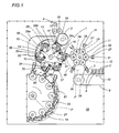
- figure 1 shows an overwrapping unit embodied in accordance with the present invention, viewed schematically from the front with certain parts omitted and illustrated in a preferred embodiment;
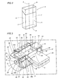
- figure 2 shows a packet of cigarettes such as will be overwrapped by the unit of figure 1, viewed in perspective,;
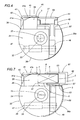
- figure 3 shows a detail of figure 1, viewed schematically and in perspective;
- figure 4 shows a detail of figure 3, viewed schematically from the side;
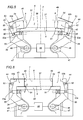
- figures 5 and 6 show the detail of figure 4, viewed schematically from the front and illustrated in two different operating positions;
- figure 7 shows the detail of figure 4, viewed schematically from the side and illustrated in a further operating position.
- With reference to figure 1,
numeral 1 denotes a unit, in its entirety, for overwrappingpackets 2 of cigarettes insheets 3 of wrapping material that consist in discrete lengths cut from acontinuous strip 4 of transparent film. - As illustrated in figure 2, each
packet 2 appears as a rectangular prism referable to a longitudinal axis denoted 5, presenting twolarger side faces 6 parallel one with another and with thelongitudinal axis 5, two smaller side orflank faces 7 disposed parallel to thelongitudinal axis 5 and at right angles to thelarger faces 6, and twoend faces 8 disposed transversely to thelongitudinal axis 5. - The
unit 1 comprises a substantially horizontal infeedconveyor 9 by whichpackets 2 are carried in ordered succession along a direction denoted 10, advancing on edge, that is to say with oneflank face 7 resting on the infeedconveyor 9, and with thelongitudinal axis 5 set transversely to thefeed direction 10. - The
unit 1 further comprises atransfer wheel 11 set in rotation clockwise (as viewed in figure 1) about ahorizontal axis 12 transverse to thefeed direction 10, by which thepackets 2 are taken up in succession from the infeedconveyor 9, and afirst folding conveyor 13 in the form of awheel 14 rotatable anticlockwise about anaxis 15 parallel to theaxis 12 of thetransfer wheel 11, by which thepackets 2 are taken up in succession from theselfsame wheel 11 at atransfer station 16, and on whichwrapping sheets 3 are taken up at afurther station 17 from afeed unit 18 and bent each over arelative packet 2 to assume an "L" profile. - Also forming part of the
unit 1 is a second foldingconveyor 19, embodied as asecond wheel 20 set in rotation clockwise about anaxis 21 parallel to theaxis 12 of thetransfer wheel 11, onto which thepackets 2 are taken up edgewise together with therelative sheets 3 folded to the "L" profile, and thesheets 3 thereupon bent further to form a tubular wrap enveloping eachpacket 2 and aligned on the relativelongitudinal axis 5, employing a sequence of steps as described and illustrated inpublication EP 1 260 442, to which reference may be made for a full description. - Proceeding beyond the
second conveyor 19, the tubular wraps are closed and sealed in conventional manner and the overwrappedpackets 2 are directed onto an outfeed conveyor (not illustrated) of theunit 1. - The infeed
conveyor 9, thetransfer wheel 11 and the first and second foldingwheels frame 25 of theunit 1, and combine to establish a wrapping path P that describes a substantially sinusoidal trajectory. - The
transfer wheel 11, which turns substantially tangential to the infeedconveyor 9, comprises a power drivendisc 26 centred on and rotatable about theaxis 12 of thewheel 11, and, mounted to thedisc 26, a plurality ofgripping heads 27 spaced apart uniformly around theaxis 12 and caused by a cam device of familiar type, not illustrated in the drawings, to pivot onrespective axes 28 parallel to theselfsame axis 12. Thegripping heads 27 are described inpublication EP 1 260 442 mentioned above. - Each gripping
head 27 comprises arespective gripper 29 projecting radially from thedisc 26 and including twojaws 30 capable of movement one relative to another in a direction transverse to the radial direction, induced by actuator means of conventional embodiment (not illustrated), between an open condition and a closed condition. - When in the closed condition, the
jaws 30 of thegripper 29 afford aslot 31 in which to accommodate apacket 2 disposed with oneflank face 7 directed toward theaxis 12 of thewheel 11 and the two larger side faces 6 in contact with theselfsame jaws 30. - In operation, with the
transfer wheel 11 set in rotation, eachpacket 2 advancing along the infeedconveyor 9 will be picked up by agripper 29 and then released to thefirst folding conveyor 13 at thetransfer station 16, substantially as indicated in theaforementioned publication EP 1 260 442, to which reference can again be made for a complete description. - The
first folding wheel 14 is equipped with a plurality ofholder mechanisms 32 equispaced around the periphery, each pivotable about arespective axis 33 extending parallel to theaxis 15 of thewheel 14 and serving to support asingle packet 2. - As illustrated in figures 3 and 4, each
holder mechanism 32 comprises afirst block 34 mounted to ashaft 35 centred on theaxis 33 aforementioned, delimited in a direction parallel to theaxis 33 by acylindrical surface 36 and aflat face 37. - Mounted to the
flat face 37 of the aforementionedfirst block 34, near to onelongitudinal edge 38, is a substantially parallelepipedsecond block 39 of which oneface 40, parallel to theflat face 37, functions as a fixed jaw interacting withmeans 41 pivotable about anaxis 42 parallel to theaxis 33 of the mechanism and serving to grip and retain a first end of thesheet 3. - The gripping and retaining means 41 appear as a lever with two arms denoted 41a and 41b, presenting a plurality of
fingers 43 and capable of movement between a position of disengagement from the fixedface 40 and a position substantially of contact with the selfsame face (see figures 1, 4 and 7). - Movement of the gripping and retaining means 41 between the aforementioned positions is induced by respective actuator means of conventional type, not illustrated, acting on the arm denoted 41a.
- As illustrated in figures 3 to 7, each
holder mechanism 32 comprises respective means by which to grip and support thepacket 2, denoted 44 in their entirety and comprising a pair ofjaws 45 mounted torespective shafts 46 pivotable aboutaxes 47 extending transversely to theaxis 33 of the mechanism and parallel to theflat face 37 of thefirst block 34. - Referring to figures 5 and 6, the
jaws 45 are capable of movement, induced by respective actuator means of familiar type (not illustrated in detail) associated with eachmechanism 32 and indicated schematically by a block denoted 48, between a first open position (figure 5), and a second closed position (figure 6) in which their substantiallyquadrangular contact ends 49 are placed at opposite ends of the aforementionedflat face 37, separated longitudinally by a distance marginally less than the longitudinal dimension of thepacket 2. - Associated rigidly with a
face 50 of eachcontact end 49 directed toward thefirst block 34, is afirst plate 51 projecting toward theopposite contact end 49 and designed, when thejaws 45 are closed, to engage theside face 6 of thepacket 2 directed toward theflat face 37 of theblock 34. - Each
jaw 45 carries afulcrum pivot 52 extending parallel to theaforementioned axis 47, and aclamp element 53 mounted at an intermediate point to thepivot 52, consisting in a lever with twoarms latter arm 53b presents asecond plate 54 at the free end, combining with thefirst plate 51 to pinch and restrain thepacket 2. - In particular, during the closing movement of the gripping and supporting
means 44, the free end of the arm denoted 53a is engaged and checked by a fixedstop 55 that induces an angular movement of theclamp element 53 about thepivot 52 against the action of a coil spring (of conventional type, not illustrated) wound around thepivot 52, between a position of disengagement illustrated in figure 5, and a position in which thesecond plate 54 engages theremaining side face 6 of thepacket 2, thereby combining with the correspondingfirst plate 51 to grip thepacket 2, as illustrated in figure 6. - It will be seen moreover that the
first plate 51 is separated from theflat face 37 by a given distance D in such a way as to create avoid 56, for reasons of access that will become apparent in due course. - It will be seen also, in figures 3 to 7, that the aforementioned
cylindrical surface 36 of thefirst block 34 presents aportion 36a, extending from alongitudinal edge 57 opposite to the aforementionedlongitudinal edge 38, furnished with a plurality ofsuction holes 58 connected to a source of negative pressure not illustrated in the drawings. - The
aforementioned portion 36a of thecylindrical surface 36 combines with thesuction holes 58 to provide means by which a second end of thesheet 3 is held and restrained. - In operation, with the
transfer wheel 11 and thefirst folding wheel 14 set in rotation about theirrespective axes single packet 2 is released by agripping head 27 to acorresponding holder mechanism 32 at thetransfer station 16, as thejaws 30 of thegripper 29 are distanced from thelarger faces 6 and thejaws 45 of the gripping and supportingmeans 44 simultaneously close on the two end faces 8 of thepacket 2. - As the packet advances to the
next station 17, asheet 3 of film is supplied by thefeed unit 18 to therelative holder mechanism 32, and pinned at the first end by the gripping and retaining means 41. - As the
folding wheel 14 rotates on itsaxis 15 and theholder mechanism 32 is caused at the same time to pivot on itsown axis 33 by actuator means of conventional type (not illustrated), thesheet 3 encounters afixed restraint 59 of curved profile, substantially concentric with thewheel 14 and presenting aninternal surface 59a withsuction holes 59b connected to a source of negative pressure (not indicated), by which it is drawn flat progressively against thelarger side face 6 of thepacket 2 located farther from theflat face 37 of theblock 34 and then bent over theadjoining flank face 7 to assume an "L" profile. - The
restraint 59, therelative surface 59a and thesuction holes 59b combine to establish fixed folder means. - At the point of exit from the
fixed restraint 59, the second part of thesheet 3 is attracted to theaforementioned portion 36a presented by thecylindrical surface 36 of thefirst block 34, and held by suction generated through theholes 58. - As the
folding wheel 14 continues to rotate, theholder mechanism 32 in question advances beyond the point of exit from therestraint 59 and into astation 60 at which thepacket 2 is transferred to the second foldingwheel 20, which is equipped with a plurality of pivotingU-shaped pockets 61 each presenting aback wall 62 and twoside members 63. - As it passes through the
transfer station 60, thepacket 2 is directed gradually from theholder mechanism 32 into thepocket 61. During the course of the transfer, as discernible in figures 1 to 7, one of the twoside members 63 will penetrate gradually into theaforementioned void 56 and thus smooth thesheet 3, still pinned at one end by the gripping andretaining means 41, against thelarger side face 6 of thepacket 2 directed toward theflat face 37 of thefirst block 34. - To advantage, the holding and restraining means afforded by the
holes 58 generate an aspirating action on the trailing part of thesheet 3 such as will attract the selfsame sheet and ensure that it remains perfectly under control when smoothed by theside member 63 of thepocket 61 against therelative side face 6 of thepacket 2, and when sliding over the aspiratingportion 36a of thecylindrical surface 36. - The step that takes place on the second folding
wheel 20, in familiar manner, is that of completing and securing the tubular wrap around thepacket 2.
Claims (9)
- A unit for overwrapping products, in particular packets (2) of substantially rectangular prismatic shape presenting two larger side faces (6) parallel one with another and with a longitudinal axis (5), two smaller flank faces (7) disposed parallel to the longitudinal axis (5) and normal to the larger faces (6), and two end faces (8) normal to the longitudinal axis (5), comprising:- a first folding conveyor (13) rotatable about a relative axis (15) and performing the initial steps of an operation whereby a sheet (3) of wrapping material is folded around the side and flank faces (6, 7) of the packet (2);- a plurality of holder mechanisms (32) mounted peripherally to the first folding conveyor (13), each pivotable about a respective axis (33) parallel to the axis (15) of rotation and serving to support respective single packets (2) disposed with the longitudinal axis (5) parallel to the selfsame axis (15);- means (41), associated with each of the holder mechanisms (32), by which to grip and retain a first end of the sheet (3);- a second folding conveyor (19) rotatable about an axis (21) parallel to the axis (15) of the first folding conveyor (13), by which the operation of wrapping the sheet (3) around the four side and flank faces (6, 7) of the packet (2) is completed,characterized
in that each holder mechanism (32) of the first folding conveyor (13) comprises means (36a, 58) by which to hold and restrain a second end of the sheet (3). - A unit for overwrapping packets as in claim 1, comprising fixed folder means (59, 59a) combining with the holder mechanisms (32) to perform the initial folding steps.
- A unit for overwrapping packets as in claim 1, wherein the second end of the sheet is (3) held and restrained by means (36a, 58) operating at least along a stretch of the path (P) described by the first folding conveyor (13) that extends between a point of exit from the fixed folder means (59, 59b) and a transfer station (60) interconnecting the first folding conveyor (13) and the second folding conveyor (19).
- A unit for overwrapping packets as in claims 1 to 3, wherein the holding and restraining means (36a, 58) consist in suction means.
- A unit for overwrapping packets as in claim 4, wherein the holder mechanism (32) comprises a block (34) mounted to a shaft (35) rotatable about a relative axis (33), delimited at least in part by a substantially cylindrical surface (36) presenting a respective portion (36a) furnished with suction holes (58).
- A unit for overwrapping packets as in claims 1 to 5, wherein the packet (2) is gripped and supported on the holder mechanism (32) in a position interposed between the means (41) serving to grip and retain a first end of the sheet (3) and the means (36a, 58) serving to hold and restrain a second end of the sheet (3), through the action of means (44) consisting in a pair of jaws (45) designed to engage the two end faces (8) of the packet (2), which lie transverse to the axis (33) of rotation of the mechanism (32).
- A unit for overwrapping packets as in claim 6, wherein the gripping and supporting means (44) comprise a pair of plates (51, 54) associated with each jaw (45) and positioned to engage the two larger side faces (6) of the packet (2).
- A method of overwrapping products, in particular packets (3) of substantially rectangular prismatic shape presenting two larger side faces (6) parallel one with another and with a longitudinal axis (5), two smaller flank faces (7) disposed parallel to the longitudinal axis (5) and normal to the larger faces (6), and two end faces (8) normal to the longitudinal axis (5),
characterized
in that it includes the steps of:- feeding single packets (2) to rotating holder mechanisms (32) of a first folding wheel (14), in such a way that each packet (2) is positioned with its longitudinal axis (5) parallel to the axis (15) of rotation of the first folding wheel (14);- gripping each packet (2) by two faces (8) disposed transversely to the axis (15) of rotation of the first folding wheel (14);- feeding a sheet (3) of wrapping material to each holder mechanism (32);- pinning a first end of the sheet (3) to the mechanism (32);- effecting initial folding steps, by which the sheet (3) is wrapped around the side and flank faces (6, 7) of the packet;- holding and restraining a second free end of the sheet (3) on the mechanism (32);- transferring the packet (2) and the sheet (3) to a second folding wheel (20). - A method as in claim 8, including the step, subsidiary and subsequent to the step of gripping the packet (2) by two faces (8) disposed transversely to the axis (15) of rotation of the first folding wheel (14), of gripping opposite end portions of the two larger side faces (6) presented by the packet (2).
Applications Claiming Priority (1)
| Application Number | Priority Date | Filing Date | Title |
|---|---|---|---|
| IT000598A ITBO20040598A1 (en) | 2004-09-27 | 2004-09-27 | UNIT FOR THE OVERWRAPPING OF PRODUCTS, IN PARTICULAR PACKAGES, AND THE RELATIVE SURVEYING METHOD |
Publications (3)
| Publication Number | Publication Date |
|---|---|
| EP1640268A2 true EP1640268A2 (en) | 2006-03-29 |
| EP1640268A3 EP1640268A3 (en) | 2006-05-17 |
| EP1640268B1 EP1640268B1 (en) | 2007-11-28 |
Family
ID=35285261
Family Applications (1)
| Application Number | Title | Priority Date | Filing Date |
|---|---|---|---|
| EP05020385A Expired - Lifetime EP1640268B1 (en) | 2004-09-27 | 2005-09-19 | A unit for overwrapping products, in particular packets, and a relative overwrapping method |
Country Status (6)
| Country | Link |
|---|---|
| US (1) | US7328553B2 (en) |
| EP (1) | EP1640268B1 (en) |
| JP (1) | JP4571564B2 (en) |
| CN (1) | CN100560431C (en) |
| DE (1) | DE602005003525T2 (en) |
| IT (1) | ITBO20040598A1 (en) |
Cited By (4)
| Publication number | Priority date | Publication date | Assignee | Title |
|---|---|---|---|---|
| DE102005059618A1 (en) * | 2005-12-12 | 2007-06-14 | Focke & Co.(Gmbh & Co. Kg) | Method and device for wrapping packages |
| IT201800000567A1 (en) * | 2018-01-05 | 2019-07-05 | Gd Spa | Wrapping method and packing machine to make a sealed wrapping of smoking articles stabilized by heat sealing |
| WO2020141298A1 (en) * | 2018-12-31 | 2020-07-09 | British American Tobacco (Investments) Limited | Apparatus and method for packaging tobacco industry products |
| US11805807B2 (en) | 2016-04-22 | 2023-11-07 | G.D S.P.A. | Diagnostic method for analysing the operation of an automatic machine which processes products in the tobacco industry |
Families Citing this family (6)
| Publication number | Priority date | Publication date | Assignee | Title |
|---|---|---|---|---|
| US20100119452A1 (en) * | 2007-06-13 | 2010-05-13 | Takeda Pharmaceutical Company Limited | Screening method |
| ITBO20130180A1 (en) * | 2013-04-22 | 2014-10-23 | P A As | CARRYING MACHINE FOR SWEET PRODUCTS. |
| ITUB20154801A1 (en) * | 2015-10-16 | 2017-04-16 | Gd Spa | Packing machine and wrapping method to make a packet of smoking items containing two groups of smoking items each other distinct. |
| PL3501300T3 (en) | 2017-12-19 | 2021-01-25 | G.D. S.P.A | Production line in the tobacco industry and method for inspecting it |
| CN113086275B (en) * | 2021-06-09 | 2021-08-31 | 长沙学院 | VR glasses lens encapsulation equipment for teaching |
| IT202100029750A1 (en) * | 2021-11-24 | 2023-05-24 | Jones & Co Inc R A | A method of packing articles into boxes and a packing device operating in accordance with that method |
Family Cites Families (9)
| Publication number | Priority date | Publication date | Assignee | Title |
|---|---|---|---|---|
| GB1233900A (en) * | 1967-10-17 | 1971-06-03 | ||
| DD134621A1 (en) * | 1977-12-22 | 1979-03-14 | Werner Kmoch | DEVICE FOR THE CONTINUOUS WRAPPING OF BONBONS |
| IT1244234B (en) * | 1990-06-11 | 1994-07-08 | Gd Spa | METHOD FOR THE PRODUCTION OF TUBULAR WRAPS. |
| US5301489A (en) * | 1992-08-04 | 1994-04-12 | B.F.B. S.P.A. | Conveying device with levers for wrapping machines designed for delicate products, equipped with a gripping device for strips of material for wrapping products, and machine with said conveying device |
| IT1304026B1 (en) * | 1998-07-08 | 2001-03-02 | Gd Spa | METHOD AND MACHINE FOR WRAPPING A PRODUCT. |
| IT1308994B1 (en) * | 1999-02-12 | 2002-01-15 | Gd Spa | METHOD AND MACHINE FOR WRAPPING ARTICLES. |
| IT1309687B1 (en) * | 1999-05-03 | 2002-01-30 | Gd Spa | METHOD AND DEVICE FOR THE SUPPLY OF GROUPS OF CIGARETTES TO A CONTINUOUS WRAPPING LINE OF A PACKAGING MACHINE |
| ITBO20010290A1 (en) * | 2001-05-11 | 2002-11-11 | Gd Spa | METHOD FOR THE OVER-WRAPPING OF PACKAGES |
| ITBO20020261A1 (en) * | 2002-05-06 | 2003-11-06 | Gd Spa | PACKAGE OVER-WRAPPING UNIT |
-
2004
- 2004-09-27 IT IT000598A patent/ITBO20040598A1/en unknown
-
2005
- 2005-09-15 JP JP2005268321A patent/JP4571564B2/en not_active Expired - Fee Related
- 2005-09-19 EP EP05020385A patent/EP1640268B1/en not_active Expired - Lifetime
- 2005-09-19 DE DE602005003525T patent/DE602005003525T2/en not_active Expired - Lifetime
- 2005-09-22 US US11/231,778 patent/US7328553B2/en not_active Expired - Fee Related
- 2005-09-27 CN CNB2005101089009A patent/CN100560431C/en not_active Expired - Fee Related
Cited By (5)
| Publication number | Priority date | Publication date | Assignee | Title |
|---|---|---|---|---|
| DE102005059618A1 (en) * | 2005-12-12 | 2007-06-14 | Focke & Co.(Gmbh & Co. Kg) | Method and device for wrapping packages |
| US11805807B2 (en) | 2016-04-22 | 2023-11-07 | G.D S.P.A. | Diagnostic method for analysing the operation of an automatic machine which processes products in the tobacco industry |
| US12336559B2 (en) | 2016-04-22 | 2025-06-24 | G.D S.P.A. | Diagnostic method for analyzing the operation of an automatic machine which processes products in the tobacco industry |
| IT201800000567A1 (en) * | 2018-01-05 | 2019-07-05 | Gd Spa | Wrapping method and packing machine to make a sealed wrapping of smoking articles stabilized by heat sealing |
| WO2020141298A1 (en) * | 2018-12-31 | 2020-07-09 | British American Tobacco (Investments) Limited | Apparatus and method for packaging tobacco industry products |
Also Published As
| Publication number | Publication date |
|---|---|
| ITBO20040598A1 (en) | 2004-12-27 |
| DE602005003525D1 (en) | 2008-01-10 |
| US7328553B2 (en) | 2008-02-12 |
| JP4571564B2 (en) | 2010-10-27 |
| CN100560431C (en) | 2009-11-18 |
| CN1757567A (en) | 2006-04-12 |
| DE602005003525T2 (en) | 2008-11-27 |
| JP2006096418A (en) | 2006-04-13 |
| EP1640268A3 (en) | 2006-05-17 |
| EP1640268B1 (en) | 2007-11-28 |
| US20060064944A1 (en) | 2006-03-30 |
Similar Documents
| Publication | Publication Date | Title |
|---|---|---|
| EP0940339B1 (en) | Continuous product wrapping method and machine | |
| CN111874303B (en) | Method and apparatus for manufacturing storage bags that are packaged and contain refillable materials. | |
| EP1640268B1 (en) | A unit for overwrapping products, in particular packets, and a relative overwrapping method | |
| EP0771731A1 (en) | Process and apparatus for assembly-packaging pellet-like articles | |
| JP2003104316A (en) | How to overwrap a parcel | |
| EP2942294A1 (en) | Wrapping method and wrapping machine for confectionery products | |
| US6574941B1 (en) | Method and machine for banding groups of sheets | |
| US6901721B2 (en) | Unit for overwrapping packets | |
| RU2226486C2 (en) | Method and apparatus for packaging of articles from cigarette block | |
| US7555877B2 (en) | Rotating-head machine for packaging products in sealed film | |
| US20010028139A1 (en) | Method and machine for banding groups of sheets | |
| JP5461876B2 (en) | Tobacco product wrapping unit and method | |
| EP1321365B1 (en) | Method of wrapping elongated articles in groups | |
| RU2228887C2 (en) | Cigarette packing machine | |
| EP1659064B1 (en) | A method and a unit for overwrapping products, and packets in particular | |
| EP1319597B1 (en) | Method and unit for transferring wrappings | |
| EP1150886B1 (en) | Method and machine for wrapping articles | |
| CS234685B1 (en) | Apparatus for wrapping prismatic objects |
Legal Events
| Date | Code | Title | Description |
|---|---|---|---|
| PUAI | Public reference made under article 153(3) epc to a published international application that has entered the european phase |
Free format text: ORIGINAL CODE: 0009012 |
|
| AK | Designated contracting states |
Kind code of ref document: A2 Designated state(s): AT BE BG CH CY CZ DE DK EE ES FI FR GB GR HU IE IS IT LI LT LU LV MC NL PL PT RO SE SI SK TR |
|
| AX | Request for extension of the european patent |
Extension state: AL BA HR MK YU |
|
| PUAL | Search report despatched |
Free format text: ORIGINAL CODE: 0009013 |
|
| AK | Designated contracting states |
Kind code of ref document: A3 Designated state(s): AT BE BG CH CY CZ DE DK EE ES FI FR GB GR HU IE IS IT LI LT LU LV MC NL PL PT RO SE SI SK TR |
|
| AX | Request for extension of the european patent |
Extension state: AL BA HR MK YU |
|
| 17P | Request for examination filed |
Effective date: 20060831 |
|
| AKX | Designation fees paid |
Designated state(s): AT BE BG CH CY CZ DE DK EE ES FI FR GB GR HU IE IS IT LI LT LU LV MC NL PL PT RO SE SI SK TR |
|
| GRAP | Despatch of communication of intention to grant a patent |
Free format text: ORIGINAL CODE: EPIDOSNIGR1 |
|
| GRAS | Grant fee paid |
Free format text: ORIGINAL CODE: EPIDOSNIGR3 |
|
| GRAA | (expected) grant |
Free format text: ORIGINAL CODE: 0009210 |
|
| AK | Designated contracting states |
Kind code of ref document: B1 Designated state(s): AT BE BG CH CY CZ DE DK EE ES FI FR GB GR HU IE IS IT LI LT LU LV MC NL PL PT RO SE SI SK TR |
|
| REG | Reference to a national code |
Ref country code: GB Ref legal event code: FG4D |
|
| REG | Reference to a national code |
Ref country code: IE Ref legal event code: FG4D |
|
| REG | Reference to a national code |
Ref country code: CH Ref legal event code: EP |
|
| REF | Corresponds to: |
Ref document number: 602005003525 Country of ref document: DE Date of ref document: 20080110 Kind code of ref document: P |
|
| REG | Reference to a national code |
Ref country code: CH Ref legal event code: NV Representative=s name: BUGNION S.A. |
|
| PG25 | Lapsed in a contracting state [announced via postgrant information from national office to epo] |
Ref country code: NL Free format text: LAPSE BECAUSE OF FAILURE TO SUBMIT A TRANSLATION OF THE DESCRIPTION OR TO PAY THE FEE WITHIN THE PRESCRIBED TIME-LIMIT Effective date: 20071128 Ref country code: ES Free format text: LAPSE BECAUSE OF FAILURE TO SUBMIT A TRANSLATION OF THE DESCRIPTION OR TO PAY THE FEE WITHIN THE PRESCRIBED TIME-LIMIT Effective date: 20080311 Ref country code: SE Free format text: LAPSE BECAUSE OF FAILURE TO SUBMIT A TRANSLATION OF THE DESCRIPTION OR TO PAY THE FEE WITHIN THE PRESCRIBED TIME-LIMIT Effective date: 20080228 |
|
| NLV1 | Nl: lapsed or annulled due to failure to fulfill the requirements of art. 29p and 29m of the patents act | ||
| PG25 | Lapsed in a contracting state [announced via postgrant information from national office to epo] |
Ref country code: LT Free format text: LAPSE BECAUSE OF FAILURE TO SUBMIT A TRANSLATION OF THE DESCRIPTION OR TO PAY THE FEE WITHIN THE PRESCRIBED TIME-LIMIT Effective date: 20071128 Ref country code: FI Free format text: LAPSE BECAUSE OF FAILURE TO SUBMIT A TRANSLATION OF THE DESCRIPTION OR TO PAY THE FEE WITHIN THE PRESCRIBED TIME-LIMIT Effective date: 20071128 Ref country code: IS Free format text: LAPSE BECAUSE OF FAILURE TO SUBMIT A TRANSLATION OF THE DESCRIPTION OR TO PAY THE FEE WITHIN THE PRESCRIBED TIME-LIMIT Effective date: 20080328 Ref country code: BG Free format text: LAPSE BECAUSE OF FAILURE TO SUBMIT A TRANSLATION OF THE DESCRIPTION OR TO PAY THE FEE WITHIN THE PRESCRIBED TIME-LIMIT Effective date: 20080228 Ref country code: LV Free format text: LAPSE BECAUSE OF FAILURE TO SUBMIT A TRANSLATION OF THE DESCRIPTION OR TO PAY THE FEE WITHIN THE PRESCRIBED TIME-LIMIT Effective date: 20071128 Ref country code: SI Free format text: LAPSE BECAUSE OF FAILURE TO SUBMIT A TRANSLATION OF THE DESCRIPTION OR TO PAY THE FEE WITHIN THE PRESCRIBED TIME-LIMIT Effective date: 20071128 Ref country code: PL Free format text: LAPSE BECAUSE OF FAILURE TO SUBMIT A TRANSLATION OF THE DESCRIPTION OR TO PAY THE FEE WITHIN THE PRESCRIBED TIME-LIMIT Effective date: 20071128 |
|
| PG25 | Lapsed in a contracting state [announced via postgrant information from national office to epo] |
Ref country code: AT Free format text: LAPSE BECAUSE OF FAILURE TO SUBMIT A TRANSLATION OF THE DESCRIPTION OR TO PAY THE FEE WITHIN THE PRESCRIBED TIME-LIMIT Effective date: 20071128 |
|
| PG25 | Lapsed in a contracting state [announced via postgrant information from national office to epo] |
Ref country code: CZ Free format text: LAPSE BECAUSE OF FAILURE TO SUBMIT A TRANSLATION OF THE DESCRIPTION OR TO PAY THE FEE WITHIN THE PRESCRIBED TIME-LIMIT Effective date: 20071128 Ref country code: DK Free format text: LAPSE BECAUSE OF FAILURE TO SUBMIT A TRANSLATION OF THE DESCRIPTION OR TO PAY THE FEE WITHIN THE PRESCRIBED TIME-LIMIT Effective date: 20071128 |
|
| ET | Fr: translation filed | ||
| PG25 | Lapsed in a contracting state [announced via postgrant information from national office to epo] |
Ref country code: RO Free format text: LAPSE BECAUSE OF FAILURE TO SUBMIT A TRANSLATION OF THE DESCRIPTION OR TO PAY THE FEE WITHIN THE PRESCRIBED TIME-LIMIT Effective date: 20071128 Ref country code: SK Free format text: LAPSE BECAUSE OF FAILURE TO SUBMIT A TRANSLATION OF THE DESCRIPTION OR TO PAY THE FEE WITHIN THE PRESCRIBED TIME-LIMIT Effective date: 20071128 Ref country code: BE Free format text: LAPSE BECAUSE OF FAILURE TO SUBMIT A TRANSLATION OF THE DESCRIPTION OR TO PAY THE FEE WITHIN THE PRESCRIBED TIME-LIMIT Effective date: 20071128 |
|
| PG25 | Lapsed in a contracting state [announced via postgrant information from national office to epo] |
Ref country code: PT Free format text: LAPSE BECAUSE OF FAILURE TO SUBMIT A TRANSLATION OF THE DESCRIPTION OR TO PAY THE FEE WITHIN THE PRESCRIBED TIME-LIMIT Effective date: 20080428 |
|
| PLBE | No opposition filed within time limit |
Free format text: ORIGINAL CODE: 0009261 |
|
| STAA | Information on the status of an ep patent application or granted ep patent |
Free format text: STATUS: NO OPPOSITION FILED WITHIN TIME LIMIT |
|
| 26N | No opposition filed |
Effective date: 20080829 |
|
| PG25 | Lapsed in a contracting state [announced via postgrant information from national office to epo] |
Ref country code: GR Free format text: LAPSE BECAUSE OF FAILURE TO SUBMIT A TRANSLATION OF THE DESCRIPTION OR TO PAY THE FEE WITHIN THE PRESCRIBED TIME-LIMIT Effective date: 20080229 |
|
| PG25 | Lapsed in a contracting state [announced via postgrant information from national office to epo] |
Ref country code: MC Free format text: LAPSE BECAUSE OF NON-PAYMENT OF DUE FEES Effective date: 20080930 Ref country code: EE Free format text: LAPSE BECAUSE OF FAILURE TO SUBMIT A TRANSLATION OF THE DESCRIPTION OR TO PAY THE FEE WITHIN THE PRESCRIBED TIME-LIMIT Effective date: 20071128 |
|
| PG25 | Lapsed in a contracting state [announced via postgrant information from national office to epo] |
Ref country code: IE Free format text: LAPSE BECAUSE OF NON-PAYMENT OF DUE FEES Effective date: 20080919 Ref country code: CY Free format text: LAPSE BECAUSE OF FAILURE TO SUBMIT A TRANSLATION OF THE DESCRIPTION OR TO PAY THE FEE WITHIN THE PRESCRIBED TIME-LIMIT Effective date: 20071128 |
|
| GBPC | Gb: european patent ceased through non-payment of renewal fee |
Effective date: 20090919 |
|
| PG25 | Lapsed in a contracting state [announced via postgrant information from national office to epo] |
Ref country code: HU Free format text: LAPSE BECAUSE OF FAILURE TO SUBMIT A TRANSLATION OF THE DESCRIPTION OR TO PAY THE FEE WITHIN THE PRESCRIBED TIME-LIMIT Effective date: 20080529 Ref country code: LU Free format text: LAPSE BECAUSE OF NON-PAYMENT OF DUE FEES Effective date: 20080919 |
|
| PG25 | Lapsed in a contracting state [announced via postgrant information from national office to epo] |
Ref country code: TR Free format text: LAPSE BECAUSE OF FAILURE TO SUBMIT A TRANSLATION OF THE DESCRIPTION OR TO PAY THE FEE WITHIN THE PRESCRIBED TIME-LIMIT Effective date: 20071128 |
|
| PGFP | Annual fee paid to national office [announced via postgrant information from national office to epo] |
Ref country code: CH Payment date: 20100930 Year of fee payment: 6 |
|
| PG25 | Lapsed in a contracting state [announced via postgrant information from national office to epo] |
Ref country code: GB Free format text: LAPSE BECAUSE OF NON-PAYMENT OF DUE FEES Effective date: 20090919 |
|
| PGFP | Annual fee paid to national office [announced via postgrant information from national office to epo] |
Ref country code: FR Payment date: 20100930 Year of fee payment: 6 |
|
| PG25 | Lapsed in a contracting state [announced via postgrant information from national office to epo] |
Ref country code: IT Free format text: LAPSE BECAUSE OF NON-PAYMENT OF DUE FEES Effective date: 20080930 |
|
| REG | Reference to a national code |
Ref country code: CH Ref legal event code: PL |
|
| REG | Reference to a national code |
Ref country code: FR Ref legal event code: ST Effective date: 20120531 |
|
| PG25 | Lapsed in a contracting state [announced via postgrant information from national office to epo] |
Ref country code: CH Free format text: LAPSE BECAUSE OF NON-PAYMENT OF DUE FEES Effective date: 20110930 Ref country code: LI Free format text: LAPSE BECAUSE OF NON-PAYMENT OF DUE FEES Effective date: 20110930 |
|
| PG25 | Lapsed in a contracting state [announced via postgrant information from national office to epo] |
Ref country code: FR Free format text: LAPSE BECAUSE OF NON-PAYMENT OF DUE FEES Effective date: 20110930 |
|
| PGFP | Annual fee paid to national office [announced via postgrant information from national office to epo] |
Ref country code: DE Payment date: 20240927 Year of fee payment: 20 |
|
| REG | Reference to a national code |
Ref country code: DE Ref legal event code: R071 Ref document number: 602005003525 Country of ref document: DE |