EP1640115A1 - Dust collection system - Google Patents
Dust collection system Download PDFInfo
- Publication number
- EP1640115A1 EP1640115A1 EP05019855A EP05019855A EP1640115A1 EP 1640115 A1 EP1640115 A1 EP 1640115A1 EP 05019855 A EP05019855 A EP 05019855A EP 05019855 A EP05019855 A EP 05019855A EP 1640115 A1 EP1640115 A1 EP 1640115A1
- Authority
- EP
- European Patent Office
- Prior art keywords
- housing
- dust
- motor
- blower assembly
- debris
- Prior art date
- Legal status (The legal status is an assumption and is not a legal conclusion. Google has not performed a legal analysis and makes no representation as to the accuracy of the status listed.)
- Withdrawn
Links
- 239000000428 dust Substances 0.000 title claims abstract description 192
- 230000008878 coupling Effects 0.000 claims abstract description 33
- 238000010168 coupling process Methods 0.000 claims abstract description 33
- 238000005859 coupling reaction Methods 0.000 claims abstract description 33
- 238000013022 venting Methods 0.000 claims abstract description 14
- 239000002184 metal Substances 0.000 claims description 2
- SGPGESCZOCHFCL-UHFFFAOYSA-N Tilisolol hydrochloride Chemical compound [Cl-].C1=CC=C2C(=O)N(C)C=C(OCC(O)C[NH2+]C(C)(C)C)C2=C1 SGPGESCZOCHFCL-UHFFFAOYSA-N 0.000 claims 1
- 230000007246 mechanism Effects 0.000 description 4
- 239000000853 adhesive Substances 0.000 description 3
- 230000001070 adhesive effect Effects 0.000 description 3
- 238000010276 construction Methods 0.000 description 2
- 239000004593 Epoxy Substances 0.000 description 1
- 239000004568 cement Substances 0.000 description 1
- 150000001875 compounds Chemical class 0.000 description 1
- 230000006835 compression Effects 0.000 description 1
- 238000007906 compression Methods 0.000 description 1
- 238000001514 detection method Methods 0.000 description 1
- 238000012423 maintenance Methods 0.000 description 1
- 238000004519 manufacturing process Methods 0.000 description 1
- 239000000463 material Substances 0.000 description 1
- 238000013021 overheating Methods 0.000 description 1
- 230000003068 static effect Effects 0.000 description 1
- 239000002023 wood Substances 0.000 description 1
Images



Classifications
-
- B—PERFORMING OPERATIONS; TRANSPORTING
- B24—GRINDING; POLISHING
- B24B—MACHINES, DEVICES, OR PROCESSES FOR GRINDING OR POLISHING; DRESSING OR CONDITIONING OF ABRADING SURFACES; FEEDING OF GRINDING, POLISHING, OR LAPPING AGENTS
- B24B55/00—Safety devices for grinding or polishing machines; Accessories fitted to grinding or polishing machines for keeping tools or parts of the machine in good working condition
- B24B55/06—Dust extraction equipment on grinding or polishing machines
- B24B55/10—Dust extraction equipment on grinding or polishing machines specially designed for portable grinding machines, e.g. hand-guided
-
- B—PERFORMING OPERATIONS; TRANSPORTING
- B24—GRINDING; POLISHING
- B24B—MACHINES, DEVICES, OR PROCESSES FOR GRINDING OR POLISHING; DRESSING OR CONDITIONING OF ABRADING SURFACES; FEEDING OF GRINDING, POLISHING, OR LAPPING AGENTS
- B24B23/00—Portable grinding machines, e.g. hand-guided; Accessories therefor
Definitions
- the present invention relates to the field of power tools, and particularly, to a dust collection system for use with a portable planer.
- the present invention is not limited to any particular type of power tool.
- Portable planers are useful tools for any workshop. However, like many power tools, portable planers can generate significant amounts of dust and debris, such as wood chips or shavings, during use. Therefore, a number of systems have been developed for use with portable planers for collecting said dust and debris.
- Currently available dust collection systems may indude a dust hood, which a user couples with the portable planer, for capturing dust and debris.
- the dust hood will typically include a vacuum attachment, such as for connecting a vacuum hose of a central vacuum system. These systems rely on suction force provided by the vacuum to draw dust and debris from the dust hood into a receptacle of the vacuum system.
- a drawback to this system is that the dust hood and vacuum system may not be induded with the portable planer and thus, may have to be purchased as separate accessories and connected with the portable planer by the user. Further, such vacuum systems may take up a lot of space and may be relatively expensive.
- a number of portable planers include built-in dust collection systems.
- the built-in systems include a dust hood coupled to the planer for capturing dust and debris generated during use of the planer.
- the dust hood typically includes a blower, which is powered by the planer's motor, for directing dust/debris into an attached bag or receptacle.
- these systems no longer require a user to purchase separate components, such as a vacuum unit, to direct dust/debris from the dust hood, they are not without problems. For instance, because they implement a blower that is powered by the planer motor, these built-in systems may experience problems with power draw.
- planer motors indude a thermal overload for detecting when the motor becomes overheated. Upon detection of overheating, the thermal overload will trip the circuit breaker, thereby causing the portable planer to shut down.
- the planer motor has to power both the portable planer and the blower of the dust hood, it may be vulnerable to overload, This may be especially true if, for example, the portable planer is set to a relatively large depth of cut. Therefore, a user may have to limit the planer's depth of cut in order to avoid overloading the planer motor and causing shut down. The end result is that the user is not getting optimal performance from the portable planer because the capabilities of the portable planer must be limited to avoid overloading the planer motor.
- the integrated dust collection system included a power source, independent from the planer motor. thereby improving performance over current systems by allowing a user to operate the portable planer without limiting its functionality.
- a first aspect of the present invention is directed to an auxiliary dust collection system including a housing, a blower assembly, and a motor.
- the housing is configured for substantially directly coupling to a dust hood of a dust and debris-generating power tool.
- the blower assembly is contained within the housing. Further, the blower assembly is configured to both draw dust and debris generated by the power tool into the housing and to vent the dust and debris from the housing.
- the motor is contained within the housing and is operably coupled with the blower assembly. Further, the motor is sized and dedicated for powering the blower assembly and is also capable of electrically coupling to a standard electrical supply.
- the auxiliary dust collection system is configured for venting solely the dust and debris-generating power tool.
- An additional aspect of the present invention is directed to an auxiliary dust collection system including a dust hood, a housing, a blower assembly, and a motor.
- the dust hood is configured for substantially directly coupling to a dust and debris-generating power tool.
- the housing is configured for substantially directly coupling to the dust hood.
- the blower assembly is contained within the housing. Further, the blower assembly is configured for venting solely the dust and debris-generating power tool by both drawing dust and debris generated by the power tool into the housing and venting the dust and debris from the housing.
- the motor is contained within the housing and is operably coupled with the blower assembly. Further, the motor is sized and dedicated for powering the blower assembly and is also capable of electrically coupling to a standard electrical supply. Additionally, the blower assembly is coupled to a drive shaft of the motor.
- a further aspect of the present invention is directed to an auxiliary dust collection system for a portable planer, the system including a dust hood, a housing. a blower assembly, and a motor.
- the dust hood includes an inlet and an outlet formed therein.
- the inlet of the dust hood is configured for substantially directly coupling to the portable planer.
- the housing indudes an inlet and an outlet formed therein.
- the inlet of the housing is configured for substantially directly coupling to the outlet of the dust hood.
- the blower assembly is contained within the housing. Further, the blower assembly is configured for venting solely the portable planer by drawing dust and debris generated by the portable planer into the housing, via the housing inlet, and venting the dust and debris from the housing, via the housing outlet.
- the motor is contained within the housing and is operably coupled with the blower assembly. Further, the motor is sized and dedicated for powering the blower assembly and is also capable of electrically coupling to a standard electrical supply. Additionally, the blower assembly is coupled to a drive shaft of the motor and is configured to draw dust and debris into the housing in a first direction and to vent dust and debris from the housing in a second direction, the second direction being substantially perpendicular to the first direction.
- FIGS. 1 through 8 exemplary embodiments of the present invention are shown.
- an auxiliary dust collection system 100 includes a housing 102.
- the housing 102 is configured for substantially directly coupling to a dust hood 200 of a dust and debris-generating power tool 300.
- the power tool 300 is a portable planer.
- the auxiliary dust collection system 100 further includes a blower assembly 104.
- the blower assembly 104 is contained within the housing 102 and is configured to draw dust and debris generated by the portable planer 300 into the housing 102. Additionally, the blower assembly 104 is configured to vent the dust and debris from the housing 102.
- the auxiliary dust collection system 100 further includes an auxiliary motor 106.
- the auxiliary motor 106 is contained within the housing 102 and is operably coupled with the blower assembly 104.
- the auxiliary motor 106 powers the blower assembly 104, thereby allowing the blower assembly to pull dust and debris into an inlet 110 of the housing 102.
- the dust and debris is then directed through the housing 102 by the auxiliary motor 106 and blower assembly 104 and is vented from an outlet 122 of the housing 102.
- the inlet 110 and outlet 122 of the housing 102 are apertures formed by the housing.
- the auxiliary motor 106 is sized and dedicated for powering the blower assembly 104.
- the auxiliary motor 106 is also capable of electrically coupling to a standard electrical supply.
- the auxiliary dust collection system 100 of the present invention is connected with the portable planer 300 to assist in providing increased dust collection capabilities beyond that provided by dust collection systems currently employed with portable planers.
- the auxiliary dust collection system 100 of the present invention does not experience the power draw problems associated with current built-in dust collection systems, which are powered by the planer's motor.
- the auxiliary dust collection system 100 is configured for venting solely the portable planer 300.
- the auxiliary dust collection system 100 includes a ground device 108, such as a ground wire coupled between the housing 102 and a metal component of the power tool 300.
- the ground device 108 is configured for preventing static buildup between the power tool 300 and the housing 102 of the auxiliary dust collection system 100.
- the housing 102, the motor 106 and the blower assembly 104 of the auxiliary dust collection system 100 are configured for coupling with a dust hood 200 of a power tool 300, such that the dust hood 200, the housing 102, the motor 106 and the blower assembly 104 are in a substantially in-line orientation with respect to the power tool 300. This may allow for easier connection of component features of the system 100.
- the inlet 110 formed by the housing 102 includes a sleeve 112 configured for receiving and securing a correspondingly-shaped adapter 114 of a dust hood 200 for substantially directly connecting the dust hood 200 with the inlet 110 of the housing 102.
- the auxiliary dust collection system 100 further includes a transfer adapter 116, the transfer adapter forming an inlet end 118 and an outlet end 120.
- the inlet end 118 of the transfer adapter 116 is configured for coupling with the outlet 122 formed by the housing 102.
- the inlet end 118 of the transfer adapter 116 and/or the housing outlet 122 may be variously contoured to correspond with each other and to maximize flow through of dust and debris.
- the transfer adapter 116 is connected with the housing 102 by a plurality of hex head bolts.
- various fasteners such as pins, clips, screws, clamps, and the like may be employed to securely affix the transfer adapter 116 with the housing 102 of the auxiliary dust collection system 100.
- various mechanical connection mechanisms such as a compression lock system, snap fit system, friction fit system, latch lock system, and the like may be employed to connect the transfer adapter 116 with the outlet 122 of the housing 102 without departing from the scope and spirit of the present invention.
- various adhesives such as epoxy compounds, plastic cements, and the like may be used to connect the transfer adapter 116 with the outlet 122 of the housing 102.
- the housing outlet 122 includes a connection mechanism whereby the transfer adapter 116 is connected to the housing 102 in proximal relation to the housing outlet 122.
- the outlet end 120 of the transfer adapter 116 is configured for coupling with a dust transfer device 124.
- the auxiliary dust collection system 100 includes a dust transfer device 124.
- the dust transfer device 124 is a flexible hose member configured for coupling with the transfer adapter 116.
- the flexible hose member 124 may be secured with the outlet end 120 of the transfer adapter 116 via a clamping mechanism 132.
- the flexible hose member 124 directs dust and debris that has been exhausted from the outlet end 120 of the transfer adapter 116, via the housing outlet 122, away from the power tool 300.
- the auxiliary dust collection system 100 further includes a dust hood 200.
- the dust hood 200 is configured for substantially directly coupling to a dust and debris-generating power tool 300, such as a portable planer.
- the dust hood 200 is a standard configuration, constructed to be connected with the portable planer 300 in a manner which allows for full operation of the portable planer.
- the dust hood 200 may be connected to the frame of the portable planer 300.
- the dust hood 200 connects with the portable planer 300 proximal to the planer's cutting device in order to maximize the dust collection capabilities of the dust hood 200.
- the dust hood 200 forms an inlet 130 which allows for the collection of the dust and debris generated by the cutting device of the portable planer 300.
- the dust hood 200 is contoured so that the collected dust and debris is funneled toward an outlet 128 formed by the dust hood 200.
- the outlet 128 is an aperture formed by the dust hood 200 from which dust and debris may be vented.
- the auxiliary dust collection system 100 further includes a housing 102.
- the housing 102 is configured for substantially directly coupling to the dust hood 200.
- the dust hood 200 may be variously configured as contemplated by those of ordinary skill in the art.
- the dust hood 200 forms an enclosure, which as mentioned above, is generally contoured to funnel collected dust and debris towards the dust hood outlet 128.
- the dust hood outlet 128 is further constructed in a manner which allows it to be connected with the inlet 110 of the housing 102.
- the dust hood outlet 128 indudes an adapter 114 which connects with the housing 102.
- the housing inlet 110 may utilize a clamping mechanism 134 for securely affixing the housing inlet 110 to the dust hood outlet 128.
- the dust hood outlet 128 may include various mechanical connection systems and/or employ various fasteners, adhesives and the like to securely affix the dust hood outlet 128 to the housing 102.
- the configuration of the housing inlet 110 may also correspond with the configuration of the dust hood outlet 128.
- the dust hood outlet 128 is a generally cylindrical aperture and therefore the housing inlet 110 may be constructed as a generally cylindrical aperture to provide for secure connection and flow through for the dust and debris from the dust hood outlet 128 into and through the housing inlet 110.
- the auxiliary dust collection system 100 further indudes a blower assembly 104 and a motor 106 as discussed above.
- the blower assembly is coupled to a drive shaft 126 of the motor 106, as shown in FIG. 5.
- an auxiliary dust collection system 100 for a portable planer 300 includes a dust hood 200.
- the dust hood 200 has an inlet 130 and an outlet 128 formed therein, the inlet 130 of the dust hood being configured for substantially directly coupling to the portable planer 300.
- the auxiliary dust collection system further includes a housing 102.
- the housing 102 has an inlet 110 and an outlet 122 formed therein, the inlet 110 of the housing 102 being configured for substantially directly coupling to the outlet 128 of the dust hood 200.
- the auxiliary dust collection system 100 further includes a blower assembly 104.
- the blower assembly 104 is contained within the housing 102 and is configured for venting solely the portable planer 300 by drawing dust and debris generated by the portable planer 300 into the housing 102, via the housing inlet 110. Further, the blower assembly 104 is configured for venting the dust and debris from the housing 102, via the housing outlet 122.
- the auxiliary dust collection system further includes a motor 106.
- the motor 106 is contained within the housing 102 and is operably coupled with the blower assembly 104. Further, the motor 106 is sized and dedicated for powering the blower assembly 104. Additionally, the motor 106 is capable of electrically coupling to a standard electrical supply. In an exemplary embodiment, as shown in FIG.
- the blower assembly 104 is coupled to a drive shaft 126 of the motor 106 and is configured to draw dust and debris into the housing 102 in a first direction and to vent dust and debris from the housing 102 in a second direction, the second direction being substantially perpendicular to the first direction. This is advantageous in that dust and debris is vented away from the portable planer 300 in a direction that does not interfere with user access to the area of the planer where a workpiece exits.
- the auxiliary dust collection system 100 of the present invention may be various modular constructions.
- the dust hood 200, the housing 102, the blower assembly 104, the auxiliary motor 106, the transfer adapter 116, and the dust transfer device 124 may be provided as individual component features which may be connected.
- Various other combinations of separate and/or combined component features of the auxiliary dust collection system 100 may be utilized in a modular system without departing from the scope and spirit of the present invention.
- this modularity may enable the housing 102, the blower assembly 104 and the auxiliary motor 106 of the present invention to be retro-fitted with existing dust hoods of various portable planers.
- auxiliary dust collection system 100 for the portable planer 300 in that the modular component features of the may be removed and the various component features provided maintenance.
- auxiliary dust collection system of the present invention may assist in increasing the useful lifespan of the portable planer as it may be removed, maintained, and/or replaced without significant interference with or disassembly of the portable planer.
- the auxiliary dust collection system 100 is unitary.
- the auxiliary dust collection system 100 may be an integral system wherein the dust hood 200, the housing 102, the blower assembly 104, the motor 106, the transfer adapter 116 and the dust transfer device 124 are integrally connected with one another.
- the integral system may reduce manufacturing costs and appeal to consumers. Further, the integral system may also be specifically constructed for use with a particular power tool.
Landscapes
- Engineering & Computer Science (AREA)
- Mechanical Engineering (AREA)
- Percussive Tools And Related Accessories (AREA)
- Milling, Drilling, And Turning Of Wood (AREA)
Abstract
Description
- The present invention relates to the field of power tools, and particularly, to a dust collection system for use with a portable planer. Of course, the present invention is not limited to any particular type of power tool.
- Portable planers are useful tools for any workshop. However, like many power tools, portable planers can generate significant amounts of dust and debris, such as wood chips or shavings, during use. Therefore, a number of systems have been developed for use with portable planers for collecting said dust and debris. Currently available dust collection systems may indude a dust hood, which a user couples with the portable planer, for capturing dust and debris. The dust hood will typically include a vacuum attachment, such as for connecting a vacuum hose of a central vacuum system. These systems rely on suction force provided by the vacuum to draw dust and debris from the dust hood into a receptacle of the vacuum system. A drawback to this system is that the dust hood and vacuum system may not be induded with the portable planer and thus, may have to be purchased as separate accessories and connected with the portable planer by the user. Further, such vacuum systems may take up a lot of space and may be relatively expensive.
- In attempting to address the problems associated with the dust collection systems described above, a number of portable planers include built-in dust collection systems. The built-in systems include a dust hood coupled to the planer for capturing dust and debris generated during use of the planer. The dust hood typically includes a blower, which is powered by the planer's motor, for directing dust/debris into an attached bag or receptacle. Although these systems no longer require a user to purchase separate components, such as a vacuum unit, to direct dust/debris from the dust hood, they are not without problems. For instance, because they implement a blower that is powered by the planer motor, these built-in systems may experience problems with power draw. More specifically, many planer motors indude a thermal overload for detecting when the motor becomes overheated. Upon detection of overheating, the thermal overload will trip the circuit breaker, thereby causing the portable planer to shut down. With the built-in dust collection systems, because the planer motor has to power both the portable planer and the blower of the dust hood, it may be vulnerable to overload, This may be especially true if, for example, the portable planer is set to a relatively large depth of cut. Therefore, a user may have to limit the planer's depth of cut in order to avoid overloading the planer motor and causing shut down. The end result is that the user is not getting optimal performance from the portable planer because the capabilities of the portable planer must be limited to avoid overloading the planer motor.
- Therefore, it would be advantageous to have a dust collection system integrated with a portable planer. It would be further advantageous if the integrated dust collection system included a power source, independent from the planer motor. thereby improving performance over current systems by allowing a user to operate the portable planer without limiting its functionality.
- Accordingly, a first aspect of the present invention is directed to an auxiliary dust collection system including a housing, a blower assembly, and a motor. The housing is configured for substantially directly coupling to a dust hood of a dust and debris-generating power tool. The blower assembly is contained within the housing. Further, the blower assembly is configured to both draw dust and debris generated by the power tool into the housing and to vent the dust and debris from the housing. The motor is contained within the housing and is operably coupled with the blower assembly. Further, the motor is sized and dedicated for powering the blower assembly and is also capable of electrically coupling to a standard electrical supply. The auxiliary dust collection system is configured for venting solely the dust and debris-generating power tool.
- An additional aspect of the present invention is directed to an auxiliary dust collection system including a dust hood, a housing, a blower assembly, and a motor. The dust hood is configured for substantially directly coupling to a dust and debris-generating power tool. The housing is configured for substantially directly coupling to the dust hood. The blower assembly is contained within the housing. Further, the blower assembly is configured for venting solely the dust and debris-generating power tool by both drawing dust and debris generated by the power tool into the housing and venting the dust and debris from the housing. The motor is contained within the housing and is operably coupled with the blower assembly. Further, the motor is sized and dedicated for powering the blower assembly and is also capable of electrically coupling to a standard electrical supply. Additionally, the blower assembly is coupled to a drive shaft of the motor.
- A further aspect of the present invention is directed to an auxiliary dust collection system for a portable planer, the system including a dust hood, a housing. a blower assembly, and a motor. The dust hood includes an inlet and an outlet formed therein. The inlet of the dust hood is configured for substantially directly coupling to the portable planer. The housing indudes an inlet and an outlet formed therein. The inlet of the housing is configured for substantially directly coupling to the outlet of the dust hood. The blower assembly is contained within the housing. Further, the blower assembly is configured for venting solely the portable planer by drawing dust and debris generated by the portable planer into the housing, via the housing inlet, and venting the dust and debris from the housing, via the housing outlet. The motor is contained within the housing and is operably coupled with the blower assembly. Further, the motor is sized and dedicated for powering the blower assembly and is also capable of electrically coupling to a standard electrical supply. Additionally, the blower assembly is coupled to a drive shaft of the motor and is configured to draw dust and debris into the housing in a first direction and to vent dust and debris from the housing in a second direction, the second direction being substantially perpendicular to the first direction.
- It is to be understood that both the foregoing general description and the following detailed description are exemplary and explanatory only and are not necessarily restrictive of the invention as claimed. The accompanying drawings, which are incorporated in and constitute a part of the specification, illustrate embodiments of the invention and together with the general description, serve to explain the principles of the invention.
- The numerous advantages of the present invention are now described, with reference to the accompanying figures in which:
- FIG. 1 is a top right perspective illustration of a portable planer including a dust collection system in accordance with an exemplary embodiment of the present invention;
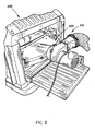
- FIG. 2 is a top left perspective illustration of a portable planer including a dust collection system in accordance with an exemplary embodiment of the present invention;
- FIG. 3 is top plan view illustrating a blower assembly and motor assembly of the dust collection system in accordance with an exemplary embodiment of the present invention;
- FIG. 4 is an isometric view illustrating a blower assembly and motor assembly of the dust collection system in accordance with an exemplary embodiment of the present invention;
- FIG. 5 is a side view illustrating an inlet aperture of a blower assembly of the dust collection system in accordance with an exemplary embodiment of the present invention;
- FIG. 6 is front plan view illustrating an outlet aperture of a blower assembly of the dust collection system in accordance with an exemplary embodiment of the present invention;
- FIG. 7 is a perspective top plan view illustrating a blower assembly connected with a dust and debris transfer assembly in accordance with an exemplary embodiment of the present invention; and
- FIG. 8 is a perspective bottom plan view illustrating a blower assembly connected with a dust and debris transfer assembly in accordance with an exemplary embodiment of the present invention.
- Reference will now be made In detail to the presently preferred embodiments of the invention, examples of which are illustrated in the accompanying drawings.
- Referring generally now to FIGS. 1 through 8, exemplary embodiments of the present invention are shown.
- In a first aspect of the present invention, an auxiliary
dust collection system 100 includes ahousing 102. Thehousing 102 is configured for substantially directly coupling to adust hood 200 of a dust and debris-generatingpower tool 300. In an exemplary embodiment, thepower tool 300 is a portable planer. - The auxiliary
dust collection system 100 further includes ablower assembly 104. Theblower assembly 104 is contained within thehousing 102 and is configured to draw dust and debris generated by theportable planer 300 into thehousing 102. Additionally, theblower assembly 104 is configured to vent the dust and debris from thehousing 102. - The auxiliary
dust collection system 100 further includes anauxiliary motor 106. Theauxiliary motor 106 is contained within thehousing 102 and is operably coupled with theblower assembly 104. In a current embodiment, theauxiliary motor 106 powers theblower assembly 104, thereby allowing the blower assembly to pull dust and debris into aninlet 110 of thehousing 102. The dust and debris is then directed through thehousing 102 by theauxiliary motor 106 andblower assembly 104 and is vented from anoutlet 122 of thehousing 102. In a present embodiment, theinlet 110 andoutlet 122 of thehousing 102 are apertures formed by the housing. In an exemplary embodiment, theauxiliary motor 106 is sized and dedicated for powering theblower assembly 104. In further embodiments, theauxiliary motor 106 is also capable of electrically coupling to a standard electrical supply. - The auxiliary
dust collection system 100 of the present invention is connected with theportable planer 300 to assist in providing increased dust collection capabilities beyond that provided by dust collection systems currently employed with portable planers. By implementing anauxiliary motor 106 to power theblower assembly 104, the auxiliarydust collection system 100 of the present invention does not experience the power draw problems associated with current built-in dust collection systems, which are powered by the planer's motor. In an exemplary embodiment, the auxiliarydust collection system 100 is configured for venting solely theportable planer 300. - In further embodiments, the auxiliary
dust collection system 100 includes aground device 108, such as a ground wire coupled between thehousing 102 and a metal component of thepower tool 300. Theground device 108 is configured for preventing static buildup between thepower tool 300 and thehousing 102 of the auxiliarydust collection system 100. - In an exemplary embodiment, as shown in FIG. 1, the
housing 102, themotor 106 and theblower assembly 104 of the auxiliarydust collection system 100 are configured for coupling with adust hood 200 of apower tool 300, such that thedust hood 200, thehousing 102, themotor 106 and theblower assembly 104 are in a substantially in-line orientation with respect to thepower tool 300. This may allow for easier connection of component features of thesystem 100. - In additional embodiments, the
inlet 110 formed by thehousing 102 includes asleeve 112 configured for receiving and securing a correspondingly-shapedadapter 114 of adust hood 200 for substantially directly connecting thedust hood 200 with theinlet 110 of thehousing 102. - In a current embodiment, the auxiliary
dust collection system 100 further includes atransfer adapter 116, the transfer adapter forming aninlet end 118 and anoutlet end 120. Theinlet end 118 of thetransfer adapter 116 is configured for coupling with theoutlet 122 formed by thehousing 102. For example, theinlet end 118 of thetransfer adapter 116 and/or thehousing outlet 122 may be variously contoured to correspond with each other and to maximize flow through of dust and debris. In the current embodiment, thetransfer adapter 116 is connected with thehousing 102 by a plurality of hex head bolts. It is contemplated that various fasteners, such as pins, clips, screws, clamps, and the like may be employed to securely affix thetransfer adapter 116 with thehousing 102 of the auxiliarydust collection system 100. Alternatively, various mechanical connection mechanisms, such as a compression lock system, snap fit system, friction fit system, latch lock system, and the like may be employed to connect thetransfer adapter 116 with theoutlet 122 of thehousing 102 without departing from the scope and spirit of the present invention. It is further contemplated that various adhesives, such as epoxy compounds, plastic cements, and the like may be used to connect thetransfer adapter 116 with theoutlet 122 of thehousing 102. It is further contemplated that thehousing outlet 122 includes a connection mechanism whereby thetransfer adapter 116 is connected to thehousing 102 in proximal relation to thehousing outlet 122. Theoutlet end 120 of thetransfer adapter 116 is configured for coupling with adust transfer device 124. - In further embodiments, the auxiliary
dust collection system 100 includes adust transfer device 124. Preferably, thedust transfer device 124 is a flexible hose member configured for coupling with thetransfer adapter 116. For example, theflexible hose member 124 may be secured with theoutlet end 120 of thetransfer adapter 116 via aclamping mechanism 132. Theflexible hose member 124 directs dust and debris that has been exhausted from theoutlet end 120 of thetransfer adapter 116, via thehousing outlet 122, away from thepower tool 300. It is contemplated that various mechanical connections systems, fasteners, and/or adhesives, as previously described, may be utilized alone or in combination with one another to secure the connection of thedust transfer device 124 with the transfer adapter 916 without departing from the scope and spirit of the present invention. - In an additional aspect of the present invention, the auxiliary
dust collection system 100 further includes adust hood 200. Thedust hood 200 is configured for substantially directly coupling to a dust and debris-generatingpower tool 300, such as a portable planer. Preferably, thedust hood 200 is a standard configuration, constructed to be connected with theportable planer 300 in a manner which allows for full operation of the portable planer. For example, thedust hood 200 may be connected to the frame of theportable planer 300. Preferably, thedust hood 200 connects with theportable planer 300 proximal to the planer's cutting device in order to maximize the dust collection capabilities of thedust hood 200. In a current embodiment, thedust hood 200 forms aninlet 130 which allows for the collection of the dust and debris generated by the cutting device of theportable planer 300. In further embodiments, thedust hood 200 is contoured so that the collected dust and debris is funneled toward anoutlet 128 formed by thedust hood 200. Preferably, theoutlet 128 is an aperture formed by thedust hood 200 from which dust and debris may be vented. - The auxiliary
dust collection system 100 further includes ahousing 102. Thehousing 102 is configured for substantially directly coupling to thedust hood 200. Thedust hood 200 may be variously configured as contemplated by those of ordinary skill in the art. In the current embodiment, thedust hood 200 forms an enclosure, which as mentioned above, is generally contoured to funnel collected dust and debris towards thedust hood outlet 128. Thedust hood outlet 128 is further constructed in a manner which allows it to be connected with theinlet 110 of thehousing 102. Preferably, thedust hood outlet 128 indudes anadapter 114 which connects with thehousing 102. In further embodiments, as shown in FIG. 7, thehousing inlet 110 may utilize aclamping mechanism 134 for securely affixing thehousing inlet 110 to thedust hood outlet 128. Alternatively, thedust hood outlet 128 may include various mechanical connection systems and/or employ various fasteners, adhesives and the like to securely affix thedust hood outlet 128 to thehousing 102. The configuration of thehousing inlet 110 may also correspond with the configuration of thedust hood outlet 128. In a current embodiment, thedust hood outlet 128 is a generally cylindrical aperture and therefore thehousing inlet 110 may be constructed as a generally cylindrical aperture to provide for secure connection and flow through for the dust and debris from thedust hood outlet 128 into and through thehousing inlet 110. - The auxiliary
dust collection system 100 further indudes ablower assembly 104 and amotor 106 as discussed above. In an exemplary embodiment, the blower assembly is coupled to adrive shaft 126 of themotor 106, as shown in FIG. 5. - In a further aspect of the present invention, an auxiliary
dust collection system 100 for aportable planer 300 includes adust hood 200. Thedust hood 200 has aninlet 130 and anoutlet 128 formed therein, theinlet 130 of the dust hood being configured for substantially directly coupling to theportable planer 300. The auxiliary dust collection system further includes ahousing 102. Thehousing 102 has aninlet 110 and anoutlet 122 formed therein, theinlet 110 of thehousing 102 being configured for substantially directly coupling to theoutlet 128 of thedust hood 200. The auxiliarydust collection system 100 further includes ablower assembly 104. Theblower assembly 104 is contained within thehousing 102 and is configured for venting solely theportable planer 300 by drawing dust and debris generated by theportable planer 300 into thehousing 102, via thehousing inlet 110. Further, theblower assembly 104 is configured for venting the dust and debris from thehousing 102, via thehousing outlet 122. The auxiliary dust collection system further includes amotor 106. Themotor 106 is contained within thehousing 102 and is operably coupled with theblower assembly 104. Further, themotor 106 is sized and dedicated for powering theblower assembly 104. Additionally, themotor 106 is capable of electrically coupling to a standard electrical supply. In an exemplary embodiment, as shown in FIG. 5, theblower assembly 104 is coupled to adrive shaft 126 of themotor 106 and is configured to draw dust and debris into thehousing 102 in a first direction and to vent dust and debris from thehousing 102 in a second direction, the second direction being substantially perpendicular to the first direction. This is advantageous in that dust and debris is vented away from theportable planer 300 in a direction that does not interfere with user access to the area of the planer where a workpiece exits. - It is contemplated that the auxiliary
dust collection system 100 of the present invention may be various modular constructions. For example, in one embodiment, thedust hood 200, thehousing 102, theblower assembly 104, theauxiliary motor 106, thetransfer adapter 116, and thedust transfer device 124 may be provided as individual component features which may be connected. Various other combinations of separate and/or combined component features of the auxiliarydust collection system 100 may be utilized in a modular system without departing from the scope and spirit of the present invention. For example, this modularity may enable thehousing 102, theblower assembly 104 and theauxiliary motor 106 of the present invention to be retro-fitted with existing dust hoods of various portable planers. This may assist in increasing the useful lifespan of the auxiliarydust collection system 100 for theportable planer 300 in that the modular component features of the may be removed and the various component features provided maintenance. Further, the auxiliary dust collection system of the present invention may assist in increasing the useful lifespan of the portable planer as it may be removed, maintained, and/or replaced without significant interference with or disassembly of the portable planer. - In additional embodiments, the auxiliary
dust collection system 100 is unitary. For example, the auxiliarydust collection system 100 may be an integral system wherein thedust hood 200, thehousing 102, theblower assembly 104, themotor 106, thetransfer adapter 116 and thedust transfer device 124 are integrally connected with one another. The integral system may reduce manufacturing costs and appeal to consumers. Further, the integral system may also be specifically constructed for use with a particular power tool. - It is believed that the present invention and many of its attendant advantages will be understood by the forgoing description. It is also believed that it will be apparent that various changes may be made in the form, construction and arrangement of the components thereof without departing from the scope and spirit of the invention or without sacrificing all of its material advantages. The form herein before described being merely an explanatory embodiment thereof. It is the intention of the following claims to encompass and include such changes.
Claims (12)
- An auxiliary dust collection system, comprising:a housing configured for directly coupling to a dust hood of a dust and debris-generating power tool,a blower assembly contained within the housing, the blower assembly being configured to both draw dust and debris generated by the power tool into the housing and to vent the dust and debris from the housing; anda motor contained within the housing, the motor being operably coupled with the blower assembly, the motor being sized and dedicated for powering the blower assembly, the motor being capable of electrically coupling to a standard electrical supply,wherein the auxiliary dust collection system is configured for venting solely the dust and debris-generating power tool.
- An auxiliary dust collection system, comprising:a dust hood being configured for directly coupling to a dust and debris-generating power tool;a housing configured for directly coupling to the dust hood;a blower assembly contained within the housing, the blower assembly being configured for venting solely the dust and debris-generating power tool by both drawing dust and debris generated by the power tool into the housing and venting the dust and debris from the housing; anda motor contained within the housing, the motor being operably coupled with the blower assembly, the motor being sized and dedicated for powering the blower assembly, the motor being capable of electrically coupling to a standard electrical supply,wherein the blower assembly is coupled to a drive shaft of the motor.
- An auxiliary dust collection system for a portable planer, comprising:a dust hood having an inlet and an outlet formed therein, the inlet of the dust hood being configured for substantially directly coupling to the portable planer;a housing having an inlet and an outlet formed therein, the inlet of the housing being configured for substantially directly coupling to the outlet of the dust hood;a blower assembly contained within the housing, the blower assembly being configured for venting solely the portable planer by drawing dust and debris generated by the portable planer into the housing, via the housing inlet, and venting the dust and debris from the housing via the housing outlet; anda motor contained within the housing, the motor being operably coupled with the blower assembly, the motor being sized and dedicated for powering the blower assembly, the motor being capable of electrically coupling to a standard electrical supply,wherein the blower assembly is coupled to a drive shaft of the motor and is configured to draw dust and debris into the housing in a first direction and to vent dust and debris from the housing in a second direction, the second direction being substantially perpendicular to the first direction.
- An auxiliary dust collection system as claimed in claim 1. 2 or 3 further comprising a ground wire coupled between the housing and a metal component of the power tool.
- An auxiliary dust collection system as daimed in claim 1, 2 or 3 wherein the housing, the motor and the blower assembly are configured for coupling with a dust hood of a power tool, such that the dust hood, the housing, the motor and the blower assembly are in an in-line orientation with respect to the power tool.
- An auxiliary dust collection system as claimed in claim 1, 2 or 3 wherein the housing forms an inlet having a sleeve configured for receiving and securing a correspondingly-shaped adapter of a dust hood for directly connecting the dust hood with the inlet of the housing.
- An auxiliary dust collection system as claimed in claim 1, 2 or 3 further comprising a transfer adapter, the transfer adapter forming an inlet end and an outlet end, the inlet end of the transfer adapter being configured for coupling with an outlet formed by the housing, the outlet end of the transfer adapter being configured for coupling with a flexible hose member.
- An auxiliary dust collection system as claimed in daim 7, further comprising a flexible hose member, the flexible hose member being configured for coupling with the transfer adapter and for directing dust and debris exhausted from the transfer adapter via the housing outlet away from the power tool.
- An auxiliary dust collection system as claimed in claim 8, wherein the auxiliary dust collection system is unitary.
- An auxiliary dust collection system as claimed in claim 1, 2 or 3, wherein an outlet formed by the dust hood includes an adapter for directly connecting with an inlet formed by the housing, the dust hood adapter being received and secured within a correspondingly-shaped sleeve of the housing inlet.
- An auxiliary dust collection system as claimed in claim 1, 2 or 3 wherein the outlet of the dust hood includes an adapter for directly connecting with the inlet of the housing, the dust hood adapter being received and secured within a correspondingly-shaped sleeve of the housing inlet.
- An auxiliary dust collection system as claimed in claim 11, further comprising a flexible hose member for connecting with the housing outlet, the flexible hose member for directing dust and debris exhausted from the housing outlet away from the power tool.
Applications Claiming Priority (2)
| Application Number | Priority Date | Filing Date | Title |
|---|---|---|---|
| US61220104P | 2004-09-22 | 2004-09-22 | |
| US11/220,355 US20060075594A1 (en) | 2004-09-22 | 2005-09-06 | Dust collection system |
Publications (1)
| Publication Number | Publication Date |
|---|---|
| EP1640115A1 true EP1640115A1 (en) | 2006-03-29 |
Family
ID=35385431
Family Applications (1)
| Application Number | Title | Priority Date | Filing Date |
|---|---|---|---|
| EP05019855A Withdrawn EP1640115A1 (en) | 2004-09-22 | 2005-09-13 | Dust collection system |
Country Status (2)
| Country | Link |
|---|---|
| US (1) | US20060075594A1 (en) |
| EP (1) | EP1640115A1 (en) |
Cited By (1)
| Publication number | Priority date | Publication date | Assignee | Title |
|---|---|---|---|---|
| CN110935244A (en) * | 2019-12-19 | 2020-03-31 | 湖州钧皓服饰有限公司 | Cloth cutting machine apparatus maintenance device that clothing production field was used |
Families Citing this family (2)
| Publication number | Priority date | Publication date | Assignee | Title |
|---|---|---|---|---|
| US20090139048A1 (en) * | 2007-11-30 | 2009-06-04 | Williams Danny P | Power tool dust-collecting assembly and accessories |
| USD1046352S1 (en) * | 2023-11-30 | 2024-10-08 | Jingdezhen Baorong Trading Co., Ltd. | Dust collection control flex cuff |
Citations (3)
| Publication number | Priority date | Publication date | Assignee | Title |
|---|---|---|---|---|
| US4693323A (en) * | 1986-02-18 | 1987-09-15 | Owensby Max T | Flexible electromagnetic pulse shielding conduit |
| EP1293298A2 (en) * | 2001-09-13 | 2003-03-19 | Robert Bosch Gmbh | Power tool with dust extraction |
| US20030220060A1 (en) * | 2002-03-01 | 2003-11-27 | Steve Bures | Portable dust collection system |
Family Cites Families (2)
| Publication number | Priority date | Publication date | Assignee | Title |
|---|---|---|---|---|
| TW547299U (en) * | 2002-04-19 | 2003-08-11 | Pei-Lie Jiang | Bits collecting apparatus for carpentry machine table |
| US7296323B2 (en) * | 2002-08-21 | 2007-11-20 | Hitachi Koki Co., Ltd. | Dust collector |
-
2005
- 2005-09-06 US US11/220,355 patent/US20060075594A1/en not_active Abandoned
- 2005-09-13 EP EP05019855A patent/EP1640115A1/en not_active Withdrawn
Patent Citations (3)
| Publication number | Priority date | Publication date | Assignee | Title |
|---|---|---|---|---|
| US4693323A (en) * | 1986-02-18 | 1987-09-15 | Owensby Max T | Flexible electromagnetic pulse shielding conduit |
| EP1293298A2 (en) * | 2001-09-13 | 2003-03-19 | Robert Bosch Gmbh | Power tool with dust extraction |
| US20030220060A1 (en) * | 2002-03-01 | 2003-11-27 | Steve Bures | Portable dust collection system |
Cited By (1)
| Publication number | Priority date | Publication date | Assignee | Title |
|---|---|---|---|---|
| CN110935244A (en) * | 2019-12-19 | 2020-03-31 | 湖州钧皓服饰有限公司 | Cloth cutting machine apparatus maintenance device that clothing production field was used |
Also Published As
| Publication number | Publication date |
|---|---|
| US20060075594A1 (en) | 2006-04-13 |
Similar Documents
| Publication | Publication Date | Title |
|---|---|---|
| US11707828B2 (en) | Hand-held machine tool comprising a drive motor | |
| US10702981B2 (en) | Vacuuming-off device | |
| US11058982B2 (en) | Electric machine tool | |
| US8424615B2 (en) | System with a hand-held power tool | |
| US6293321B1 (en) | Wood planing machine with a sawdust-collecting mechanism | |
| US9517555B2 (en) | Battery operated handheld power tool | |
| US10272558B2 (en) | Power tool having an elongated housing supporting a power module | |
| US10279450B2 (en) | Hand-held power tool with a cooling unit | |
| US20150165640A1 (en) | Battery Pack Operated Hand-Held Power Tool | |
| CN109196745B (en) | Handheld power tool with disconnect switch | |
| US6651710B2 (en) | Dust-sucking and power-driving motor | |
| CN112813897A (en) | Blower fan | |
| EP4065326A1 (en) | A support arm for a hand-held work tool and a hand-held work tool comprising such a support arm | |
| CN100522436C (en) | Modular power tool | |
| JP5544143B2 (en) | Battery powered electric brush cutter | |
| US20230079761A1 (en) | Electric power tool | |
| US20060075594A1 (en) | Dust collection system | |
| EP4180184A1 (en) | A power tool, power tool accessory and coupling arrangement therefor | |
| US12597666B2 (en) | Nosecone to battery connection in power tool | |
| EP1683169B1 (en) | Switch unit with ventilation | |
| US20250178143A1 (en) | Router and debris receptacle | |
| US20250050459A1 (en) | Router and chip collector accessory therefor | |
| JP5732164B2 (en) | Battery powered electric brush cutter | |
| KR20200114574A (en) | A apparatus for suction and blowing of chargeable electric motor tool | |
| CN115224851A (en) | Electric working machine and method for manufacturing electric working machine |
Legal Events
| Date | Code | Title | Description |
|---|---|---|---|
| PUAI | Public reference made under article 153(3) epc to a published international application that has entered the european phase |
Free format text: ORIGINAL CODE: 0009012 |
|
| AK | Designated contracting states |
Kind code of ref document: A1 Designated state(s): AT BE BG CH CY CZ DE DK EE ES FI FR GB GR HU IE IS IT LI LT LU LV MC NL PL PT RO SE SI SK TR |
|
| AX | Request for extension of the european patent |
Extension state: AL BA HR MK YU |
|
| 17P | Request for examination filed |
Effective date: 20060810 |
|
| 17Q | First examination report despatched |
Effective date: 20060918 |
|
| AKX | Designation fees paid |
Designated state(s): AT BE BG CH CY CZ DE DK EE ES FI FR GB GR HU IE IS IT LI LT LU LV MC NL PL PT RO SE SI SK TR |
|
| STAA | Information on the status of an ep patent application or granted ep patent |
Free format text: STATUS: THE APPLICATION IS DEEMED TO BE WITHDRAWN |
|
| 18D | Application deemed to be withdrawn |
Effective date: 20090401 |