EP1639846B1 - A method for configuring a communication network, related network architecture and computer program product therefor - Google Patents
A method for configuring a communication network, related network architecture and computer program product therefor Download PDFInfo
- Publication number
- EP1639846B1 EP1639846B1 EP03817326A EP03817326A EP1639846B1 EP 1639846 B1 EP1639846 B1 EP 1639846B1 EP 03817326 A EP03817326 A EP 03817326A EP 03817326 A EP03817326 A EP 03817326A EP 1639846 B1 EP1639846 B1 EP 1639846B1
- Authority
- EP
- European Patent Office
- Prior art keywords
- value
- pixel
- network
- antennas
- antenna
- Prior art date
- Legal status (The legal status is an assumption and is not a legal conclusion. Google has not performed a legal analysis and makes no representation as to the accuracy of the status listed.)
- Expired - Lifetime
Links
- 238000004891 communication Methods 0.000 title claims description 31
- 238000000034 method Methods 0.000 title claims description 28
- 238000004590 computer program Methods 0.000 title claims description 3
- 238000010586 diagram Methods 0.000 claims description 23
- 230000005855 radiation Effects 0.000 claims description 22
- 230000006870 function Effects 0.000 claims description 15
- 230000008901 benefit Effects 0.000 claims description 10
- 230000001747 exhibiting effect Effects 0.000 claims description 4
- 238000005457 optimization Methods 0.000 claims 2
- 210000004027 cell Anatomy 0.000 description 22
- 230000008569 process Effects 0.000 description 12
- 238000009826 distribution Methods 0.000 description 6
- 238000012544 monitoring process Methods 0.000 description 5
- 230000006978 adaptation Effects 0.000 description 4
- 238000013461 design Methods 0.000 description 3
- 230000005672 electromagnetic field Effects 0.000 description 3
- 210000004460 N cell Anatomy 0.000 description 2
- 230000010267 cellular communication Effects 0.000 description 2
- 238000009434 installation Methods 0.000 description 2
- 230000035945 sensitivity Effects 0.000 description 2
- 230000009471 action Effects 0.000 description 1
- 230000003044 adaptive effect Effects 0.000 description 1
- 238000004458 analytical method Methods 0.000 description 1
- 230000005540 biological transmission Effects 0.000 description 1
- 238000004364 calculation method Methods 0.000 description 1
- 230000001413 cellular effect Effects 0.000 description 1
- 230000008859 change Effects 0.000 description 1
- 230000009194 climbing Effects 0.000 description 1
- 238000011161 development Methods 0.000 description 1
- 230000000694 effects Effects 0.000 description 1
- 230000006872 improvement Effects 0.000 description 1
- 230000003993 interaction Effects 0.000 description 1
- 238000011835 investigation Methods 0.000 description 1
- 238000004519 manufacturing process Methods 0.000 description 1
- 238000005259 measurement Methods 0.000 description 1
- 238000010295 mobile communication Methods 0.000 description 1
- 230000004048 modification Effects 0.000 description 1
- 238000012986 modification Methods 0.000 description 1
- 238000009828 non-uniform distribution Methods 0.000 description 1
- 230000009467 reduction Effects 0.000 description 1
- 238000011160 research Methods 0.000 description 1
- 239000007787 solid Substances 0.000 description 1
- 230000003442 weekly effect Effects 0.000 description 1
Images


Classifications
-
- H—ELECTRICITY
- H04—ELECTRIC COMMUNICATION TECHNIQUE
- H04W—WIRELESS COMMUNICATION NETWORKS
- H04W52/00—Power management, e.g. Transmission Power Control [TPC] or power classes
- H04W52/04—Transmission power control [TPC]
- H04W52/38—TPC being performed in particular situations
- H04W52/42—TPC being performed in particular situations in systems with time, space, frequency or polarisation diversity
-
- H—ELECTRICITY
- H04—ELECTRIC COMMUNICATION TECHNIQUE
- H04W—WIRELESS COMMUNICATION NETWORKS
- H04W16/00—Network planning, e.g. coverage or traffic planning tools; Network deployment, e.g. resource partitioning or cells structures
- H04W16/24—Cell structures
- H04W16/28—Cell structures using beam steering
-
- H—ELECTRICITY
- H01—ELECTRIC ELEMENTS
- H01Q—ANTENNAS, i.e. RADIO AERIALS
- H01Q3/00—Arrangements for changing or varying the orientation or the shape of the directional pattern of the waves radiated from an antenna or antenna system
- H01Q3/26—Arrangements for changing or varying the orientation or the shape of the directional pattern of the waves radiated from an antenna or antenna system varying the relative phase or relative amplitude of energisation between two or more active radiating elements; varying the distribution of energy across a radiating aperture
- H01Q3/2605—Array of radiating elements provided with a feedback control over the element weights, e.g. adaptive arrays
-
- H—ELECTRICITY
- H04—ELECTRIC COMMUNICATION TECHNIQUE
- H04W—WIRELESS COMMUNICATION NETWORKS
- H04W16/00—Network planning, e.g. coverage or traffic planning tools; Network deployment, e.g. resource partitioning or cells structures
- H04W16/18—Network planning tools
-
- H—ELECTRICITY
- H04—ELECTRIC COMMUNICATION TECHNIQUE
- H04W—WIRELESS COMMUNICATION NETWORKS
- H04W16/00—Network planning, e.g. coverage or traffic planning tools; Network deployment, e.g. resource partitioning or cells structures
- H04W16/24—Cell structures
Definitions
- the present invention relates to communication networks and was developed by paying specific attention to the possible application in configuring cellular networks and similar communication networks including antennas with respective areas of coverage (in transmission and/or reception).
- each antenna tower or mounting location such as a building
- the characteristics of each antenna e.g. the downtilt angle
- the characteristics of such a traditional antenna need to be changed after installation, a worker has to access the antenna again - e.g. by again climbing up the tower where the antenna is mounted - to re-adjust the downtilt angle or even to replace the antenna.
- US-A-6 487 416 a method and system are disclosed for controlling downtilt of an antenna in a sector of a cell of a code division multiple access (CDMA) network by utilising dynamic application of antenna downtilt based on estimated relative sector capacity.
- current network conditions are monitored, relative sector capacity is estimated, and an antenna downtilt is selected.
- the selected antenna downtilt is dynamically applied to the antenna, preferably in order to effectively maximise relative sector capacity.
- US-A-6 549 529 describes a wireless communication system including antennas having electrically controllable downtilt angles and downtilt controllers associated with each antenna.
- the downtilt controllers receive instruction from a main controller, and adjust downtilt angles of the associated antennas in accordance with the received instructions.
- control logic is implemented as a set of processes monitoring the network and keeping track of relevant parameters by measuring the load on a base station or coverage area to judge whether the base station and/or coverage area is overloaded.
- WO 03/045094 discloses systems and methods which provide communication network antenna pattern configuration for optimized network operation.
- a statistical smart antenna configuration is provided in which antenna patterns associated with various base stations of the communication network are configured to capitalize on the complex morphology and topology of a service area in providing optimized communications.
- Antenna patterns are preferably configured using merit based determinations, based upon link propagation conditions such as associated with the complex morphologies and topologies of the service area, to aggressively serve areas which are best served thereby while not serving areas which are best served by other network systems.
- antennas tilt is just one of the significant propagation characteristics of an antenna.
- changing the antenna tilt may permit to somehow vary the respective area of coverage (essentially by modifying in the directions pointed by the antenna), that kind of adjustment does not lead to any changes of the azimuth characteristics, namely the actual "shape" of the radiation diagram in the horizontal plane.
- the dynamic adaptation arrangements considered in the foregoing essentially base their operation on the concept of monitoring certain operation parameters: (for instance the traffic served, the interference level among the various cells and so on) for different tilt angles in order to subsequently select an optimum tilt value leading to a best performance level.
- the adaptation/reconfiguration process may turn out to be slow and in some cases even lead to a situation where the system is finally adapted to meet requirements that no longer exist since that requirements have significantly changed in the meantime.
- Similar examples are represented by roads or motorways likely to exhibit for short periods of time (e.g. on Sunday evenings) levels of occupancy - and therefore levels of telecommunication traffic to be served - largely in excess of the average level over the rest of the week.
- arrangements based on monitoring traffic conditions are intrinsically not adapted for use in configuring communication networks at the stage of planning, i.e. when the network is still to be deployed.
- adaptive reconfigurable antennas can play an active role in ensuring user coverage by interacting with traffic data (whether planned, predicted, or monitored) notionally on a real time basis.
- the possibility of controlling and limiting the interference level is a key parameter in order to be able to cover as a high number of users as possible while ensuring a good quality of service without changing the number of channels available.
- the object of the present invention is thus to meet these needs while overcoming the drawbacks of prior art arrangements as outlined in the foregoing.
- the present invention also relates to a corresponding network architecture and a computer program product loadable in the memory of at least one computer and including software code portions for performing the method of the invention.
- Reference to at least one computer is evidently intended to take into account that the method of the invention is adapted to be carried out in a decentralised manner, with different tasks allotted to different computers in a network.
- the basic idea underlying the presently preferred embodiment of the invention is exploiting for the purpose of configuring a communication network the possibility of adjusting the radiation diagram of an antenna (i.e. a plurality of gain values for a set of directions over a plurality of directions from the antenna) as a function i.e. of the communication traffic offered at a given portion of the coverage area and of the attenuation experienced by the signal over the propagation path between the antenna and that portion of the coverage area.
- the invention overcomes all the limitations outlined in the foregoing in respect of known solutions that use reconfigurable antennas within the context of a communication network.
- adaptation criteria are provided that may be implemented both in actual operation of a mobile network and at the planning stage thereof, without requiring by way of necessity actual deployment of the network over the area intended to be covered by a network.
- the invention gives the possibility of reconfiguring antennas in the wider sense of the term, namely both as regards tilt and as regards the azimuth configuration of the radiation diagrams i.e. by selectively and independently allotting to each direction a respective gain value.
- an objective configuration criterion is identified together with a corresponding operating process adapted for implementation in a dedicated software architecture.
- Such an architecture is capable of analysing the environment surrounding each antenna in terms of path loss (that is the attenuation to which the electromagnetic signal is subjected over the path between the antenna and each point in the area covered) and in terms of a traffic level forecast, estimated or actually measured for a given service or a complex set of services.
- Knowledge of the path loss value is in fact representative of knowledge of the area of coverage of the respective cell.
- Such data having a variable degree of reliability depending on the applications, are usually included in the facilities available with any planning instrument for mobile networks of the second and third generation.
- Information concerning the traffic offered as a function of distribution over the area served represents input data for planning networks of the third generation, which data are also useful in properly dimensioning second generation networks. Consequently, the arrangement disclosed herein does not require any appreciable information in addition to the information already currently available when planning a mobile telecommunication network.
- a preferred embodiment of the invention analyses the traffic requirements of the whole area served and derives therefrom an optimum radiation diagram for configuring the respective antenna.
- the results are optimised in terms of maximising the ratio of the traffic offered and collected in the coverage area to the attenuation experienced by the signal in the specific direction pointing to the "pixel" of the area covered being considered.
- Each single antenna can thus be configured for best serving those users that are "reachable” in terms of electromagnetic field with the minimum energy allocation in terms of signal irradiated, which in turn is a source of potentially interference with the other antennas included in the network.
- the search for the optimal configuration of the radiation diagram can be repeated for all the antennas in the network considered, by using as a final result an optimal integrated configuration related to all the radiating systems included in the network.
- the arrangement described herein also lends itself to be possibly used in reconfiguring an existing network: specifically a number of areas operating under critical conditions may be identified and one or more reconfigurable antennas substituted for existing "fixed" antennas in order to solve the problems existing in the critical areas and possibly improve the performance of the whole network.
- the configuration process can be carried out at a control center (e.g. the base station controller) of the network and enforced through those control channels that already exist in the network for the purpose of monitoring operation.
- a control center e.g. the base station controller
- the reconfiguration process is intrinsically a fast process, the only limitation being in fact provided by the availability of updated information on the environment. Reconfiguration may thus take place also repeatedly within a very short lapse of time. For instance, reconfiguration may be carried out with different frequencies during a day, in order to take into account the fact e.g. that traffic flows may not change appreciably during a good deal of the day, while being subjected to intensive modification as a result of events taking place during the weekend, during holiday periods or as a result of events such as sports and public events.
- reference 10 indicates as a whole a telecommunication system such as a mobile communication network according to any known standard.
- a GSM network or a UMTS network may be considered as examples of the so-called second and third generations (3G) of such systems.
- the invention is however applicable to any type of communication networks, even without limitation to a cellular communication network.
- the schematic representation of figure 1 exclusively represents the "fixed" part of the network, excluding the mobile terminals.
- the fixed part of the network shown includes a plurality of base stations 12 each having associated therewith at least one respective radiation system such as an antenna 14.
- Each or at least a part of the antennas 14 shown are of the kind whose radiation diagram may be selectively adjusted, thus making it possible to modify the radiation diagram of the antenna by means of electrical signals provided by the respective base station 12 depending e.g. on corresponding instructions received from base station controller 16.
- the capability of adapting the propagation characteristics of the adjustable antennas 14 considered here is not limited to adjusting the tilt angle (downtilt).
- adaptation of the antenna characteristics includes the possibility of selectively modifying the radiation diagram in the plane of the area served by the system, e.g. by possibly adding, removing lobes and/or selectively changing the mutual orientation and intensity of these lobes.
- Antennas exhibiting such features are known in the art, e.g. in the form of so-called phased-array antennas.
- the base station controller 16 is connected to the mobile switching center (MSC) 18 of the network.
- the center 18 in turn operates under the control of a network operation center 20 in possible connection with one or more other networks such as a public switched telephone network (PSTN) 22.
- PSTN public switched telephone network
- the architecture shown herein is a purely exemplary one.
- the arrangement disclosed herein may be easily operated also within the framework of different architectures such as decentralised networks providing for information and/or instructions for antenna reconfiguration being gathered and/or generated at any point in the network.
- Attenuation is proportional to the square of the distance from the signal source and, therefore, proportional to the overall area adapted to be covered with a given useful value of signal intensity (so-called “coverage area").
- Attenuation associated with the propagation path/channel between the two communicating terminals is a basic parameter to ensure connection.
- the receiver terminal i.e. a minimum signal level required - but not sufficient in general - to ensure operation
- the requirement for a minimum signal level in the presence of a given level of attenuation between the signal source and the receiver terminal can be guaranteed on the basis of basic considerations of energy balance over the communication path. This is in turn satisfied by adapting the power transmitted by the source and/or the efficiency or gain of the radiating system associated with.
- the coverage area of a given electromagnetic source is intrinsically related to the amount of traffic for that area in connection with a given service or set of services that are to be provided by the telecommunication network. Even though remarkable fluctuations exist related to the non-uniform distribution of traffic over the territory, the total amount of traffic in a cell of a cellular communication system is in fact proportional to the extension of its coverage area and thus (at least approximately) to the square of the radius of the notional circular cell equivalent to the coverage area considered.
- a preferred embodiment of the arrangement disclosed herein is thus based on the concept of regarding attenuation as a sort of "cost" factor while the traffic offered represents "benefit”.
- the territory surrounding the antenna in question can be regarded as comprised of a plurality of portions or sectors S, each including a given set of pixels P, having dimensions of e.g. 50x50 meters.
- T pixel / a pixel R bcpixel
- both the traffic and the attenuation parameters used for defining the ratio R bcpixel can either be predetermined (e.g. by way of forecast) during the planning phase of a network still to be deployed or measured, estimated or predicted during actual operation of a network already deployed once the expected levels of traffic in the -coverage area and the levels of attenuation for the pixels comprised therein are known: this may result from calculations performed on the basis of propagation models.
- Each of the pixels P in a given portion S of the covered area has an associated value of attenuation and the values of attenuation for all the pixels in the sector S investigated exhibit a minimum value a min .
- figure 2 reports an example where the resolution has been chosen equal to 30° in azimuth ( ⁇ ) while the value in elevation ( ⁇ ) is selected in such a way as to define over the coverage area annular portions having identical radial widths.
- the optimisation function defined in the foregoing is a sort of cost function where the traffic values T pixel are weighed by means of the attenuation values.
- a preferred embodiment of the arrangement shown herein aims at utilising, for each portion S of the area surrounding the antenna (defined by their coordinates ⁇ i , ⁇ j ) the corresponding value a m as the optimal value of attenuation to be compensated with the antenna gain in that direction.
- the set of the values for a m obtained for all the portions S of territory considered identifies the shape of the radiation diagram to be used for the antenna in order to ensure that the optimising function is maximised in any direction.
- G max is the maximum gain obtainable with the reconfigurable antenna and A max the maximum value in the set of the attenuation values a m obtained for the various portions of the area investigated
- G max is assigned to that portion of territory characterised by A max
- the optimal power level P feed for the reconfigurable antenna is defined as a function of the minimum amplitude of electro magnetic field E min .
- the power level in question is designated pilot power in UMTS networks and BCCH (Broadcast Control Channel) power in GSM networks. As already indicated, this is in turn related to the sensitivity of the mobile terminal.
- the information obtained is useful in that e.g. if P feed is higher than the maximum value catered for by the standard, then a substantial likelihood exists that the orographic features and the traffic distribution in the area surrounding the antenna considered are such as to suggest the relocation of the antenna or the addition of new antenna sites in the network.
- the power P feed in the cell investigated will obviously be the maximum one provided for the standard even though it will not be possible to ensure the optimisation level defined in the foregoing.
- the flowchart of figure 4 refers to the possible application of the arrangement just described to planning a mobile network such as an UMTS network.
- the parameter T m can be regarded as a measure of the traffic captured by each of the cells analysed, and may be referred to as a target with the main object of distributing the traffic uniformly among the various cells and improving the configuration process of each antenna.
- n reconfigurable cells In a step 100, the availability of n reconfigurable cells will be assumed, with n s N.
- a step 102 the configuration process described in the foregoing is applied to those n cells in the network that, when equipped with conventional, fixed antennas exhibit a level of traffic carried that more appreciably differs from the average level T m (e.g. 50% more or 50% less).
- T m the average level
- the absolute value of the positive threshold may differ from the absolute value of the negative threshold).
- the average amount of traffic (T m ) served by the N cells/antennas is evaluated.
- At least one difference threshold (which may be either positive - e.g. X% more - or negative - e.g. Y% less) with respect to the average amount of traffic (T m ) is defined.
- a subset of n "critical" antennas is then identified among the N antennas in the network for which the respective amounts of traffic reach the (positive or negative) difference threshold; n reconfigurable antennas are then substituted for these "critical" antennas.
- a step 104 performance of the network is evaluated by referring to a reconfigured network where n reconfigurable antennas have been substituted for conventional fixed antennas in the n "critical" cells identified in the foregoing. Specifically, performance of the network is evaluated in terms of distribution of the traffic carried.
- a check is made as to whether the evaluated performance level is satisfactory.
- step 106 In the case of a positive outcome of the step 106 (performance satisfactory), the system evolves to a final step 108.
- the system evolves to a step 110 where the average target value T m is increased (e.g. by 5%) and the process is repeated by evolving back to the step 102.
- the flowchart of figure 5 refers to the possible application of the arrangement just described to optimising an already existing mobile network such as an UMTS network.
- the network includes N cells/antennas out of which n cells are equipped with reconfigurable antennas. This may possibly result from the procedure shown in figure 4 having been previously applied. Again it will be assumed that n ⁇ N.
- a step 202 generally indicates the availability of information on variations in the distribution of the traffic offered, such cyclical variations occurring on a daily or weekly basis and/or as a result of public events, new dwellings or industrial/commercial activities in the area covered by the network.
- a step 204 the (re)configuration process described in the foregoing is applied to those n cells in the network equipped with reconfigurable antennas by taking into account the variation factors considered in the foregoing. It will be appreciated that such a reconfiguration need not necessarily lead to changing the radiation characteristics of all the reconfigurable antennas serving such cells.
- step 206 performance of the network as reconfigured is evaluated in terms of overall traffic carried and distribution thereof.
- a check is made as to whether the evaluated performance level is satisfactory.
- step 208 performance held not to be satisfactory
- a number of options are open for action on the network as indicated by a step 210.
- the target in terms of average traffic T m may be varied e.g. as described in the foregoing with reference to the step 110 in figure 4 .
- the number of reconfigurable antennas may be changed e.g. by increasing the value of n of an increase factor ⁇ n, thus leading to a new subset of reconfigurable antennas being defined in a step 216.
- the total number of cells can be increased thus leading in a step 220 to revising the network design.
- the arrangement disclosed herein is in no way linked to a specific sequence in which the various cells equipped with a reconfigurable antennas are analysed.
- the arrangement disclosed herein provides a means for a guided planning of the network by following an optimisation criterion of the signal levels transmitted by each fixed source in the network.
- the arrangement disclosed herein also ensures in general terms an improvement of the traffic carried and/or a reduction of the amounts of power transmitted by the cells.
- That function may thus be defined differently depending on the specific operating needs.
- Presently preferred choices are selecting the gain value for a given direction as the gain maximising a ratio (R bcpixel ) of the traffic value to the attenuation value and/or the gain optimising a cost function (f(a 0 )) wherein the traffic value and the attenuation value represent benefit and cost factors, respectively.
Landscapes
- Engineering & Computer Science (AREA)
- Computer Networks & Wireless Communication (AREA)
- Signal Processing (AREA)
- Mobile Radio Communication Systems (AREA)
Description
- The present invention relates to communication networks and was developed by paying specific attention to the possible application in configuring cellular networks and similar communication networks including antennas with respective areas of coverage (in transmission and/or reception).
- As used herein, "configuring" will generally apply both to planning networks to be deployed and to adjusting/optimising already existing networks.
- Research in the area of telecommunications and related technological development over the recent years had led to the possibility of designing and manufacturing radiating systems (i.e. antennas/aerials) adapted to modify their propagation characteristics.
- Specifically, in addition to conventional antennas - that are essentially "passive" components - electrically controllable antennas are now available for communication systems, especially for use as base stations (BTS, SRB and the like) in mobile telecommunication systems.
- The availability of these "reconfigurable" antennas (typically in the form of so-called phased-array antennas) has been so far exploited mainly in order to adapt their characteristics to the requirements of network planning while dispensing, inasmuch as possible, with the need of direct interventions at the antenna site when the antenna characteristics need to be modified.
- For instance, installation workers usually climb up each antenna tower or mounting location (such as a building) to initially adjust the characteristics of each antenna (e.g. the downtilt angle) according to the values determined at the planning stage. If, for any reasons (e.g. due to the need of reconfiguring the network), the characteristics of such a traditional antenna need to be changed after installation, a worker has to access the antenna again - e.g. by again climbing up the tower where the antenna is mounted - to re-adjust the downtilt angle or even to replace the antenna.
- Electrically controlled reconfigurable antennas dispense with such a need thanks to the possibility of remotely adjusting e.g. the antenna tilt.
- In
US-A-6 487 416 a method and system are disclosed for controlling downtilt of an antenna in a sector of a cell of a code division multiple access (CDMA) network by utilising dynamic application of antenna downtilt based on estimated relative sector capacity. Specifically, in such prior art arrangement, current network conditions are monitored, relative sector capacity is estimated, and an antenna downtilt is selected. The selected antenna downtilt is dynamically applied to the antenna, preferably in order to effectively maximise relative sector capacity. - A substantially similar arrangement is disclosed in
US-A-6 549 529 , which describes a wireless communication system including antennas having electrically controllable downtilt angles and downtilt controllers associated with each antenna. The downtilt controllers receive instruction from a main controller, and adjust downtilt angles of the associated antennas in accordance with the received instructions. - In either case, the control logic is implemented as a set of processes monitoring the network and keeping track of relevant parameters by measuring the load on a base station or coverage area to judge whether the base station and/or coverage area is overloaded.
- Further,
WO 03/045094 - Even though goring in the directions of providing a network wherein the characteristics of the various antennas can be dynamically adapted to different operating conditions, such prior art arrangements still suffer from a number of intrinsic drawback.
- In the first place, antennas tilt (e.g. downtilt) is just one of the significant propagation characteristics of an antenna. In fact, while changing the antenna tilt may permit to somehow vary the respective area of coverage (essentially by modifying in the directions pointed by the antenna), that kind of adjustment does not lead to any changes of the azimuth characteristics, namely the actual "shape" of the radiation diagram in the horizontal plane.
- Additionally, the dynamic adaptation arrangements considered in the foregoing essentially base their operation on the concept of monitoring certain operation parameters: (for instance the traffic served, the interference level among the various cells and so on) for different tilt angles in order to subsequently select an optimum tilt value leading to a best performance level.
- Such an optimisation process must be repeated for each antenna, with the possibility that the optimum tilt angle set for a given antenna at a given time may no longer be optimum after the tilt angles of one or more neighbouring antennas have been optimised in turn.
- As a consequence, the adaptation/reconfiguration process may turn out to be slow and in some cases even lead to a situation where the system is finally adapted to meet requirements that no longer exist since that requirements have significantly changed in the meantime.
- In order to better understand this, one may simply refer to those changes in the operational requirements of a communication network that may arise just for relatively short periods of time at remarkable distances over time. A typical example is given by locations (such as stadiums or other venues of sport events and the like) where large attendances - that is high traffic requirements/opportunities - may gather only for very short periods of time e.g. once a week, these location being hardly sources of any appreciable traffic over the rest of the week.
- Similar examples are represented by roads or motorways likely to exhibit for short periods of time (e.g. on Sunday evenings) levels of occupancy - and therefore levels of telecommunication traffic to be served - largely in excess of the average level over the rest of the week.
- Quite evidently, arrangements based on monitoring traffic conditions over a wide range of possible combinations of the characteristics of the various antennas in the network are exposed to the risk that the optimal configuration for effectively covering e.g. a stadium during a match is reached only when the match is over and the stadium is finally empty.
- More generally, arrangements based on monitoring traffic conditions are intrinsically not adapted for use in configuring communication networks at the stage of planning, i.e. when the network is still to be deployed.
- The need therefore exists for arrangements wherein adaptive reconfigurable antennas can play an active role in ensuring user coverage by interacting with traffic data (whether planned, predicted, or monitored) notionally on a real time basis.
- Such a need is particularly felt in the context of mobile telecommunication systems both of the second and of the third generation (3G) type.
- In second generation systems such as GSM, the possibility of controlling and limiting the interference level is a key parameter in order to be able to cover as a high number of users as possible while ensuring a good quality of service without changing the number of channels available.
- This is even more the case for third generation systems (such as UMTS) where the same frequency band is shared by various users.
- In any case, the availability of dynamic systems adapted to be reconfigured rapidly and reliably in view of changing traffic requirements is particularly appreciated in configuring communication networks at the stage of planning, i.e. when the network is still to be deployed.
- The object of the present invention is thus to meet these needs while overcoming the drawbacks of prior art arrangements as outlined in the foregoing.
- According to the present invention, that object is achieved by means of a method having the features set forth in the claims that follow.
- The present invention also relates to a corresponding network architecture and a computer program product loadable in the memory of at least one computer and including software code portions for performing the method of the invention. Reference to at least one computer is evidently intended to take into account that the method of the invention is adapted to be carried out in a decentralised manner, with different tasks allotted to different computers in a network.
- In brief, the basic idea underlying the presently preferred embodiment of the invention is exploiting for the purpose of configuring a communication network the possibility of adjusting the radiation diagram of an antenna (i.e. a plurality of gain values for a set of directions over a plurality of directions from the antenna) as a function i.e. of the communication traffic offered at a given portion of the coverage area and of the attenuation experienced by the signal over the propagation path between the antenna and that portion of the coverage area.
- Essentially, the invention overcomes all the limitations outlined in the foregoing in respect of known solutions that use reconfigurable antennas within the context of a communication network.
- In the first place, adaptation criteria are provided that may be implemented both in actual operation of a mobile network and at the planning stage thereof, without requiring by way of necessity actual deployment of the network over the area intended to be covered by a network.
- Additionally, the invention gives the possibility of reconfiguring antennas in the wider sense of the term, namely both as regards tilt and as regards the azimuth configuration of the radiation diagrams i.e. by selectively and independently allotting to each direction a respective gain value.
- This is not the case for those prior art arrangements providing for (only) the tilt angle of the antenna being adjusted: in that case, the gain values for a number of directions are changed by inevitably retaining a fixed relationship determined by the "horizontal" shape of the diagram.
- These intrinsic limitations of the prior art are dispensed with in the arrangement described herein, -which effectively permits (re)configuration of a communication network to take place i) at the planning level - i.e. before the network is actually deployed, ii) by way of adjustment/optimisation of an already existing network, and iii) during current network operation, possibly in real-time conditions.
- In a preferred embodiment of the invention, an objective configuration criterion is identified together with a corresponding operating process adapted for implementation in a dedicated software architecture. Such an architecture is capable of analysing the environment surrounding each antenna in terms of path loss (that is the attenuation to which the electromagnetic signal is subjected over the path between the antenna and each point in the area covered) and in terms of a traffic level forecast, estimated or actually measured for a given service or a complex set of services.
- Knowledge of the path loss value is in fact representative of knowledge of the area of coverage of the respective cell. Such data, having a variable degree of reliability depending on the applications, are usually included in the facilities available with any planning instrument for mobile networks of the second and third generation.
- Information concerning the traffic offered as a function of distribution over the area served, represents input data for planning networks of the third generation, which data are also useful in properly dimensioning second generation networks. Consequently, the arrangement disclosed herein does not require any appreciable information in addition to the information already currently available when planning a mobile telecommunication network.
- A preferred embodiment of the invention analyses the traffic requirements of the whole area served and derives therefrom an optimum radiation diagram for configuring the respective antenna. Preferably, the results are optimised in terms of maximising the ratio of the traffic offered and collected in the coverage area to the attenuation experienced by the signal in the specific direction pointing to the "pixel" of the area covered being considered. Each single antenna can thus be configured for best serving those users that are "reachable" in terms of electromagnetic field with the minimum energy allocation in terms of signal irradiated, which in turn is a source of potentially interference with the other antennas included in the network. The search for the optimal configuration of the radiation diagram can be repeated for all the antennas in the network considered, by using as a final result an optimal integrated configuration related to all the radiating systems included in the network.
- The arrangement described herein also lends itself to be possibly used in reconfiguring an existing network: specifically a number of areas operating under critical conditions may be identified and one or more reconfigurable antennas substituted for existing "fixed" antennas in order to solve the problems existing in the critical areas and possibly improve the performance of the whole network.
- Irrespective of whether involving the whole set of antennas in a network or only a portion of them being analysed, the configuration process can be carried out at a control center (e.g. the base station controller) of the network and enforced through those control channels that already exist in the network for the purpose of monitoring operation.
- The reconfiguration process is intrinsically a fast process, the only limitation being in fact provided by the availability of updated information on the environment. Reconfiguration may thus take place also repeatedly within a very short lapse of time. For instance, reconfiguration may be carried out with different frequencies during a day, in order to take into account the fact e.g. that traffic flows may not change appreciably during a good deal of the day, while being subjected to intensive modification as a result of events taking place during the weekend, during holiday periods or as a result of events such as sports and public events.
- The invention will now be described, by way of example only, by referring to the enclosed figures of drawing, wherein:
-
figure 1 is a diagram illustrating a telecommunication network adapted for use of the invention, -
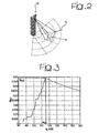
figure 2 schematically represents the basic operating principle of a preferred embodiment of the arrangement described herein, -
figure 3 is a diagram illustrative of the criterion schematically shown infigure 2 , and -
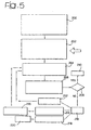
figures 4 and5 are flow charts representing steps in a configuring process as disclosed herein. - In
figure 1 , reference 10 indicates as a whole a telecommunication system such as a mobile communication network according to any known standard. - A GSM network or a UMTS network may be considered as examples of the so-called second and third generations (3G) of such systems. The invention is however applicable to any type of communication networks, even without limitation to a cellular communication network.
- The schematic representation of
figure 1 exclusively represents the "fixed" part of the network, excluding the mobile terminals. The fixed part of the network shown includes a plurality ofbase stations 12 each having associated therewith at least one respective radiation system such as anantenna 14. - Each or at least a part of the
antennas 14 shown are of the kind whose radiation diagram may be selectively adjusted, thus making it possible to modify the radiation diagram of the antenna by means of electrical signals provided by therespective base station 12 depending e.g. on corresponding instructions received frombase station controller 16. - The capability of adapting the propagation characteristics of the
adjustable antennas 14 considered here is not limited to adjusting the tilt angle (downtilt). - In the preferred embodiment shown, adaptation of the antenna characteristics includes the possibility of selectively modifying the radiation diagram in the plane of the area served by the system, e.g. by possibly adding, removing lobes and/or selectively changing the mutual orientation and intensity of these lobes.
- Antennas exhibiting such features (that is the ability of associating a selected gain value to practically each direction from the antenna over the area covered by their radiation diagram) are known in the art, e.g. in the form of so-called phased-array antennas.
- General information concerning these antennas may be found e.g. in:
- R.C. Hansen, "Microwave Scanning Antennas vol.II Array Theory And Practice, and vol.III Array Systems", Academic Press, New York 1964,
- E. Brookner, Ed. "Practical phased-array antenna systems", Artech House, Boston 1991, or
- R.J. Mailloux "Phased array antenna handbook - Pattern synthesis for linear and planar arrays" Artech House, Boston 1994.
- In the following it will be generally assumed that the
base station controller 16 is connected to the mobile switching center (MSC) 18 of the network. Thecenter 18 in turn operates under the control of anetwork operation center 20 in possible connection with one or more other networks such as a public switched telephone network (PSTN) 22. - It will be further appreciated that the architecture shown herein is a purely exemplary one. In fact, the arrangement disclosed herein may be easily operated also within the framework of different architectures such as decentralised networks providing for information and/or instructions for antenna reconfiguration being gathered and/or generated at any point in the network.
- By way of general introduction to the underlying principles of the invention, it may be worth recalling that investigations (both of theoretical and experimental nature), concerning propagation of electromagnetic signals in telecommunication systems such as mobile systems show the amplitude of the electromagnetic signal to be actually subject to a degree of attenuation higher than the theoretical attenuation defined in the so-called free space.
- In the case of propagation in the free space, attenuation is proportional to the square of the distance from the signal source and, therefore, proportional to the overall area adapted to be covered with a given useful value of signal intensity (so-called "coverage area").
- The reasons leading to attenuation being in practice higher in comparison with the free-space model are related to the essential differences existing between the free space and a real environment. Even in the absence of obstacles to propagation, the real environment is characterised by the interaction of the electromagnetic signal with the earth surface. Additionally, obstacles are always present over the propagation path.
- Similarly, in all radio links, including mobile links, attenuation associated with the propagation path/channel between the two communicating terminals is a basic parameter to ensure connection. Given a certain sensitivity of the receiver terminal (i.e. a minimum signal level required - but not sufficient in general - to ensure operation) the requirement for a minimum signal level in the presence of a given level of attenuation between the signal source and the receiver terminal can be guaranteed on the basis of basic considerations of energy balance over the communication path. This is in turn satisfied by adapting the power transmitted by the source and/or the efficiency or gain of the radiating system associated with.
- As the value of attenuation over the path increases, ensuring a proper link becomes more and more expensive in terms of energy/power, which practically corresponds to a limitation of the coverage area.
- The coverage area of a given electromagnetic source is intrinsically related to the amount of traffic for that area in connection with a given service or set of services that are to be provided by the telecommunication network. Even though remarkable fluctuations exist related to the non-uniform distribution of traffic over the territory, the total amount of traffic in a cell of a cellular communication system is in fact proportional to the extension of its coverage area and thus (at least approximately) to the square of the radius of the notional circular cell equivalent to the coverage area considered.
- A preferred embodiment of the arrangement disclosed herein is thus based on the concept of regarding attenuation as a sort of "cost" factor while the traffic offered represents "benefit".
- Therefore, once the position of a given
antenna 14 is fixed, the territory surrounding the antenna in question (seefigure 2 ) can be regarded as comprised of a plurality of portions or sectors S, each including a given set of pixels P, having dimensions of e.g. 50x50 meters. - Consequently, for each such pixel P a benefit/cost ratio can be defined as

where: - Tpixel (e.g. in Erlang) represents the traffic offered for the pixel,
- apixel (e.g. in dB) represents the attenuation over the path between the
antenna 14 and the pixel in question. - It will be appreciated that both the traffic and the attenuation parameters used for defining the ratio Rbcpixel can either be predetermined (e.g. by way of forecast) during the planning phase of a network still to be deployed or measured, estimated or predicted during actual operation of a network already deployed once the expected levels of traffic in the -coverage area and the levels of attenuation for the pixels comprised therein are known: this may result from calculations performed on the basis of propagation models.
- Each of the pixels P in a given portion S of the covered area has an associated value of attenuation and the values of attenuation for all the pixels in the sector S investigated exhibit a minimum value amin.
- An optimisation function f(a0) may then be defined as follows:

where the summation in the optimisation function extends for apixel from amin to a0 over all the pixels P in a given portion S of the covered area. - The summation indicated in the foregoing may be extended to any of the portions S, that are in turn determined on the basis of the solid angle resolution for which the radiation diagram of the antenna is to be optimised.
- This is done by using a reference system whose origin is the antenna itself. For instance,
figure 2 reports an example where the resolution has been chosen equal to 30° in azimuth (Δθ) while the value in elevation (Δϕ) is selected in such a way as to define over the coverage area annular portions having identical radial widths. - In view of the typical behaviour of the entities Tpixel and apixel, for each portion S of territory investigated, the function f (a0) exhibits a behaviour as shown by way of example in
figure 3 . Consequently, a value am exists for the abscissa infigure 3 where the optimisation function has a maximum value f (am). - Essentially, the optimisation function defined in the foregoing is a sort of cost function where the traffic values Tpixel are weighed by means of the attenuation values.
- A preferred embodiment of the arrangement shown herein aims at utilising, for each portion S of the area surrounding the antenna (defined by their coordinates Δθi,Δϕj) the corresponding value am as the optimal value of attenuation to be compensated with the antenna gain in that direction.
- Consequently, the set of the values for am obtained for all the portions S of territory considered identifies the shape of the radiation diagram to be used for the antenna in order to ensure that the optimising function is maximised in any direction.
- The relationship of identity which relates the set of the attenuation values am and the set of values that define the radiation diagram of the reconfigurable antenna must be understood in the relative sense with respect to a reference value.
- Assuming that Gmax is the maximum gain obtainable with the reconfigurable antenna and Amax the maximum value in the set of the attenuation values am obtained for the various portions of the area investigated, the maximum gain Gmax is assigned to that portion of territory characterised by Amax, while to that portion of territory characterised by a generic attenuation value ami a gain value Gmi is assigned given by the following relationship:

- Still by using the entities Amax and Gmax it is possible to define the optimal power level Pfeed for the reconfigurable antenna as a function of the minimum amplitude of electro magnetic field Emin. Specifically, the power level in question is designated pilot power in UMTS networks and BCCH (Broadcast Control Channel) power in GSM networks. As already indicated, this is in turn related to the sensitivity of the mobile terminal.
- In that respect, one needs simply refer to the well known relationship existing between the electromagnetic field level at a pixel, the transmitted power PT (in the meaning of Equivalent Isotropic Radiated Power - EIRP) from the antenna serving the cell, the path attenuation and the frequency f of the radio link.
- This typically has the form indicated in the following wherein also the measurement units for the various entities are indicated.

- In the previous relationship, the transmitted power PT can be expressed as

where Acable is the attenuation introduced by the antenna feed cables (or waveguides) which is known. - In both relationships considered in the foregoing all the terms are generally known with the exception of the power Pfeed. This may therefore be deduced from the formula. The value obtained for Pfeed must of course be compliant with the constraints set by the standards applicable for the network considered.
- In any case the information obtained is useful in that e.g. if Pfeed is higher than the maximum value catered for by the standard, then a substantial likelihood exists that the orographic features and the traffic distribution in the area surrounding the antenna considered are such as to suggest the relocation of the antenna or the addition of new antenna sites in the network.
- If no changes are made in the antenna location or if the number of the antennas in the network is not changed, the power Pfeed in the cell investigated will obviously be the maximum one provided for the standard even though it will not be possible to ensure the optimisation level defined in the foregoing.
- Conversely, if Pfeed is lower than the maximum power value catered for by the standard, the value in question can be positively used for the base station considered. In that way the optimum level is ensured while achieving a tangible advantage in terms of reducing the interference generated in the surrounding portions of the network.
- The arrangement disclosed in the foregoing can be obviously extended to any number of the antennas included in a network by applying the same criteria described in the foregoing.
- The flowchart of
figure 4 refers to the possible application of the arrangement just described to planning a mobile network such as an UMTS network. - It will be generally assumed that an existing network design is already available based on N "conventional" cells/antennas, e.g. single-lobe antennas each pointing to a fixed direction (both in azimuth and elevation). It will also be assumed that the following information is available at the level of design forecast:
- distribution of traffic offered,
- service area covered by each cell
- total amount of traffic carried,
- average amount of traffic Tm carried by the cells, and
- inter-cell interference levels.
- The parameter Tm can be regarded as a measure of the traffic captured by each of the cells analysed, and may be referred to as a target with the main object of distributing the traffic uniformly among the various cells and improving the configuration process of each antenna.
- In a
step 100, the availability of n reconfigurable cells will be assumed, with n s N. - In a
step 102 the configuration process described in the foregoing is applied to those n cells in the network that, when equipped with conventional, fixed antennas exhibit a level of traffic carried that more appreciably differs from the average level Tm (e.g. 50% more or 50% less). These are of course just indicative values, and the absolute value of the positive threshold may differ from the absolute value of the negative threshold). - Stated otherwise, in the
step 102 the average amount of traffic (Tm) served by the N cells/antennas is evaluated. At least one difference threshold (which may be either positive - e.g. X% more - or negative - e.g. Y% less) with respect to the average amount of traffic (Tm) is defined. - A subset of n "critical" antennas is then identified among the N antennas in the network for which the respective amounts of traffic reach the (positive or negative) difference threshold; n reconfigurable antennas are then substituted for these "critical" antennas.
- In a
step 104, performance of the network is evaluated by referring to a reconfigured network where n reconfigurable antennas have been substituted for conventional fixed antennas in the n "critical" cells identified in the foregoing. Specifically, performance of the network is evaluated in terms of distribution of the traffic carried. - In a step 106 a check is made as to whether the evaluated performance level is satisfactory.
- In the case of a positive outcome of the step 106 (performance satisfactory), the system evolves to a
final step 108. - In the case of a negative outcome of the step 106 (performance held not to be satisfactory), the system evolves to a
step 110 where the average target value Tm is increased (e.g. by 5%) and the process is repeated by evolving back to thestep 102. - The flowchart of
figure 5 refers to the possible application of the arrangement just described to optimising an already existing mobile network such as an UMTS network. - Again, in a
step 200 it will be assumed that the network includes N cells/antennas out of which n cells are equipped with reconfigurable antennas. This may possibly result from the procedure shown infigure 4 having been previously applied. Again it will be assumed that n ≤ N. - A
step 202 generally indicates the availability of information on variations in the distribution of the traffic offered, such cyclical variations occurring on a daily or weekly basis and/or as a result of public events, new dwellings or industrial/commercial activities in the area covered by the network. - In a
step 204, the (re)configuration process described in the foregoing is applied to those n cells in the network equipped with reconfigurable antennas by taking into account the variation factors considered in the foregoing. It will be appreciated that such a reconfiguration need not necessarily lead to changing the radiation characteristics of all the reconfigurable antennas serving such cells. - In -a
step 206, performance of the network as reconfigured is evaluated in terms of overall traffic carried and distribution thereof. - In a step 208 a check is made as to whether the evaluated performance level is satisfactory.
- In the case of a positive outcome of the step 208 (performance satisfactory), the system evolves to a
final step 210. - In the case of a negative outcome of the step 208 (performance held not to be satisfactory) a number of options are open for action on the network as indicated by a
step 210. - As a first option, in a
step 212 the target in terms of average traffic Tm may be varied e.g. as described in the foregoing with reference to thestep 110 infigure 4 . - Alternatively, in a
step 214 the number of reconfigurable antennas may be changed e.g. by increasing the value of n of an increase factor Δn, thus leading to a new subset of reconfigurable antennas being defined in astep 216. - As a further alternative, in a
step 218 the total number of cells can be increased thus leading in astep 220 to revising the network design. - After any of
steps step 204. - If the maximum level of traffic adapted to be carried by a cell is reached, the same criteria can be adopted as described with respect to the maximum power value considered in the foregoing.
- It will be appreciated that the arrangement disclosed herein is in no way linked to a specific sequence in which the various cells equipped with a reconfigurable antennas are analysed. The arrangement disclosed herein provides a means for a guided planning of the network by following an optimisation criterion of the signal levels transmitted by each fixed source in the network. The arrangement disclosed herein also ensures in general terms an improvement of the traffic carried and/or a reduction of the amounts of power transmitted by the cells.
- Of course, without prejudice to the underlying principle of the invention, the details and the embodiments may vary, also significantly, with respect to what has been described in the foregoing, just by way of example, without departing from the scope of protection of the invention as defined by the annexed claims. Specifically, those of skill in the art will appreciate that the invention is based on the general concept of determining, for each direction in the radiation diagram of an antenna a respective value of communication traffic, and selectively allotting to each direction a respective gain value as a function of e.g. the communication traffic determined for said direction and the attenuation value over the propagation path identified by that direction.
- The nature of that function may thus be defined differently depending on the specific operating needs. Presently preferred choices are selecting the gain value for a given direction as the gain maximising a ratio (Rbcpixel) of the traffic value to the attenuation value and/or the gain optimising a cost function (f(a0)) wherein the traffic value and the attenuation value represent benefit and cost factors, respectively.
- This result may be - but does not necessarily need be - achieved on the basis of the specific relationship reported in the foregoing.
- Also, those of skill in the art will appreciate that the possible field of application of the invention is in no way limited to wide area communication networks such as the UMTS networks referred to in the foregoing by way of example only. Alternative areas of application of the invention include e.g. local area networks such as WLANs in home and business contexts.
Claims (10)
- A method for configuring a communication network including a plurality, N, of antennas (14), comprising the steps of:- a) including in said plurality of antennas (14) at least one (n) reconfigurable antenna adapted to serve communication traffic in a respective coverage area, said reconfigurable antenna having a radiation diagram exhibiting a plurality of electively adjustable gain values for a set of directions (Δθi, Δϕj), each direction in said set defining a propagation path between the antenna (14) and a portion, S, of said coverage area, each portion S including a plurality of pixels, P, wherein each pixel P has an associated value of communication traffic Tpixel and a propagation path from said antenna (14) with an associated attenuation value apixel,- b) determining, for each direction (Δθ i , Δϕ j ) in said set, a reference attenuation value, am, over the propagation path defined by the direction (Δθi, Δϕj), said reference attenuation value am depending on a benefit/cost ratio, Rbc, for the pixels P included in said portion S, said benefit/cost ratio Rbc being a ratio between said communication traffic value Tpixel and said attenuation value apixel in each of said pixels P, said reference attenuation value am corresponding to the attenuation value that maximises an optimization function f(a0) defined as:

where Tpixel/apixel is said benefit/cost ratio Rbc and the summation extends from an attenuation value amin to an attenuation value a0 over all the pixels P included in said portion S of said coverage area, said attenuation value amin being the minimum value of the values of attenuation for all the pixels P included in said portion S,c) determining a maximum attenuation value, Amax, of said reference attenuation values, ami, associated to each direction (Δθ i , Δϕ j ),d) determining a maximum gain value, Gmax, of said radiation diagram of said at least one reconfigurable antenna (14) in said coverage area,e) associating said maximum gain value Gmax to the direction (Δθ i , Δϕ j ) having said maximum attenuation value Amax,f) determining for the other directions (Δθi, Δϕj) a respective gain value, Gmi, in the radiation diagram of said reconfigurable antenna (14) based on the relationship Gmi =G max -(A max -ami ). - The method of claim 1, characterised in that it includes the steps of:- determining a field intensity value, Emin, required to provide said communication traffic over the area covered by the radiation diagram of said at least one reconfigurable antenna (14),- determining a power value, Pfeed, for said antenna (14) to provide said field value Emin,- comparing said power value determined Pfeed with a maximum threshold value, and- if said power value as determined Pfeed exceeds said maximum threshold value, issuing a signal indicating that the antenna (14) is to be relocated.
- The method of claim 1, characterised in that it includes the steps of:- configuring said network as a step of planning a still undeployed network, and- determining said value of communication traffic Tpixel as a planned parameter of said still undeployed network.
- The method of claim 1, characterised in that it includes the steps of:- configuring said network as a step of managing an already existing network, and- determining said value of communication traffic Tpixel as at least one of a forecast parameter and a measured parameter of said already existing network.
- The method of claim 1, characterised in that it comprises the steps of:- determining a reference amount of traffic, Tm, served by the plurality N of antennas in the network,- setting at least one difference threshold with respect to said reference amount of traffic Tm,- identifying among said plurality of antennas N a subset n of antennas, wherein respective amounts of traffic served by each one of the antennas of said subset reach said difference threshold, and- configuring the antennas, n, in said subset as reconfigurable antennas, each having a radiation diagram exhibiting a plurality of selectively adjustable gain values for a set of directions (Δθi, Δϕ j ), each direction in said set defining a propagation path between the antenna (14) and a portion S of the respective coverage area, and- applying to the reconfigurable antennas of said subset the steps b), c), d), e) and f) to reconfigure said network.
- The method of claim 5, characterised in that it comprises the step of defining said reference amount of traffic as the average amount of traffic Tm served by said plurality of antennas.
- The method of claim 5, characterised in that it comprises the step of checking (106; 208) the performance level of said reconfigured network.
- The method of claim 7, characterised in that it comprises the steps of:- defining at least one criterion for satisfactory performance level of said network,- checking (106; 208) the performance level of said reconfigured network against said criterion, and- if said cheeking (106; 208) reveals that said performance level fails to meet said criterion, taking at least one of the steps of:- varying (110; 212) said reference amount of traffic Tm,- increasing the number n of said reconfigurable antennas in said subset, and- increasing (218) the total number N of antennas in the network.
- A network architecture for a communication network including a plurality N of antennas (14), comprising:- at least one reconfigurable antenna adapted to serve communication traffic in a respective coverage area, wherein- said at least one reconfigurable antenna has a radiation diagram exhibiting a plurality of selectively adjustable gain values for a set of directions (Δθi, Δϕj) and wherein- each direction (Δθi, Δϕj) in said set defines a propagation path between the antenna (14) and a portion, S, of said coverage area, said portion S including a plurality of pixels, P, wherein each pixel P has an associated value of communication traffic, Tpixel, and a propagation path from said antenna (14) with an associated attenuation value, apixel, and- has associated:- a reference attenuation value, am, over the propagation path defined by the direction (Δθ i , Δϕ j ), said reference attenuation value am depending on a benefit/cost ratio, Rbc, for the pixels P included in said portion S, said benefit/cost ratio Rbc being a ratio between said communication traffic value Tpixel and said attenuation value apixel in each of said pixels P, said reference attenuation value am corresponds to the attenuation value that maximises an optimization function f(a0) defined as:

where Tpixel/apixel is said benefit/cost ratio Rbc and the summation extends from an attenuation value amin to an attenuation value a0 over all the pixels P included in a given portion S of said coverage area, said attenuation value amin being the minimum value of the values of attenuation for all the pixels P included in said given portion S, and- a respective gain value, Gmi, said respective gain value Gmi being determined by means of the relationship Gmi = G max - (A max - ami ) where Amax is a maximum attenuation value of said reference attenuation values ami associated to each direction (Δθ i , Δϕ j ) in said coverage area and Gmax is the maximum gain value of said radiation diagram of said at least one reconfigurable antenna (14) associated to the direction (Δθ i , Δϕ j ) having said maximum attenuation value Amax. - A computer program product loadable in the memory of at least one computer and including software code portions for performing the method of any one of claims 1 to 8.
Applications Claiming Priority (1)
| Application Number | Priority Date | Filing Date | Title |
|---|---|---|---|
| PCT/EP2003/006800 WO2005004515A1 (en) | 2003-06-27 | 2003-06-27 | A method for configuring a communication network, related network architecture and computer program product therefor |
Publications (2)
| Publication Number | Publication Date |
|---|---|
| EP1639846A1 EP1639846A1 (en) | 2006-03-29 |
| EP1639846B1 true EP1639846B1 (en) | 2010-02-24 |
Family
ID=33560722
Family Applications (1)
| Application Number | Title | Priority Date | Filing Date |
|---|---|---|---|
| EP03817326A Expired - Lifetime EP1639846B1 (en) | 2003-06-27 | 2003-06-27 | A method for configuring a communication network, related network architecture and computer program product therefor |
Country Status (9)
| Country | Link |
|---|---|
| US (1) | US7286854B2 (en) |
| EP (1) | EP1639846B1 (en) |
| CN (1) | CN100574488C (en) |
| AR (1) | AR044907A1 (en) |
| AT (1) | ATE459225T1 (en) |
| AU (1) | AU2003250852A1 (en) |
| BR (2) | BR0318371A (en) |
| DE (1) | DE60331480D1 (en) |
| WO (1) | WO2005004515A1 (en) |
Cited By (1)
| Publication number | Priority date | Publication date | Assignee | Title |
|---|---|---|---|---|
| US11936445B2 (en) | 2020-11-23 | 2024-03-19 | Elisa Oyj | Method for optimizing antenna directions in a communications network |
Families Citing this family (66)
| Publication number | Priority date | Publication date | Assignee | Title |
|---|---|---|---|---|
| US20050021123A1 (en) | 2001-04-30 | 2005-01-27 | Jurgen Dorn | Variable speed self-expanding stent delivery system and luer locking connector |
| US7848782B2 (en) * | 2005-02-02 | 2010-12-07 | Interdigital Technology Corporation | Method and apparatus for improving network resource planning in a wireless communication network |
| US8055265B2 (en) | 2005-06-30 | 2011-11-08 | Telecom Italia S.P.A. | Method and system for selecting radiation diagrams of antennas for mobile-radio communication networks |
| EP1915113B1 (en) | 2005-08-17 | 2010-03-03 | C.R. Bard, Inc. | Variable speed stent delivery system |
| US11026822B2 (en) | 2006-01-13 | 2021-06-08 | C. R. Bard, Inc. | Stent delivery system |
| US8808346B2 (en) | 2006-01-13 | 2014-08-19 | C. R. Bard, Inc. | Stent delivery system |
| BRPI0621817A2 (en) | 2006-06-30 | 2012-09-18 | Telecom Italia Spa | Method and system for configuring an antenna site equipped with at least one reconfigurable antenna in a communication network, and communication network |
| GB0615658D0 (en) | 2006-08-07 | 2006-09-13 | Angiomed Ag | Hand-held actuator device |
| US7787823B2 (en) | 2006-09-15 | 2010-08-31 | Corning Cable Systems Llc | Radio-over-fiber (RoF) optical fiber cable system with transponder diversity and RoF wireless picocellular system using same |
| US7848654B2 (en) | 2006-09-28 | 2010-12-07 | Corning Cable Systems Llc | Radio-over-fiber (RoF) wireless picocellular system with combined picocells |
| US8873585B2 (en) | 2006-12-19 | 2014-10-28 | Corning Optical Communications Wireless Ltd | Distributed antenna system for MIMO technologies |
| US8111998B2 (en) | 2007-02-06 | 2012-02-07 | Corning Cable Systems Llc | Transponder systems and methods for radio-over-fiber (RoF) wireless picocellular systems |
| GB0713497D0 (en) | 2007-07-11 | 2007-08-22 | Angiomed Ag | Device for catheter sheath retraction |
| US20100054746A1 (en) | 2007-07-24 | 2010-03-04 | Eric Raymond Logan | Multi-port accumulator for radio-over-fiber (RoF) wireless picocellular systems |
| US8175459B2 (en) | 2007-10-12 | 2012-05-08 | Corning Cable Systems Llc | Hybrid wireless/wired RoF transponder and hybrid RoF communication system using same |
| WO2009081376A2 (en) | 2007-12-20 | 2009-07-02 | Mobileaccess Networks Ltd. | Extending outdoor location based services and applications into enclosed areas |
| US8204544B2 (en) * | 2008-03-27 | 2012-06-19 | Rockstar Bidco, LP | Agile remote radio head |
| AU2010210766A1 (en) | 2009-02-03 | 2011-09-15 | Corning Cable Systems Llc | Optical fiber-based distributed antenna systems, components, and related methods for monitoring and configuring thereof |
| US9673904B2 (en) | 2009-02-03 | 2017-06-06 | Corning Optical Communications LLC | Optical fiber-based distributed antenna systems, components, and related methods for calibration thereof |
| WO2010091004A1 (en) | 2009-02-03 | 2010-08-12 | Corning Cable Systems Llc | Optical fiber-based distributed antenna systems, components, and related methods for calibration thereof |
| US8289910B2 (en) * | 2009-04-24 | 2012-10-16 | Kathrein-Werke Kg | Device for receiving and transmitting mobile telephony signals with multiple transmit-receive branches |
| US8548330B2 (en) | 2009-07-31 | 2013-10-01 | Corning Cable Systems Llc | Sectorization in distributed antenna systems, and related components and methods |
| US8280259B2 (en) | 2009-11-13 | 2012-10-02 | Corning Cable Systems Llc | Radio-over-fiber (RoF) system for protocol-independent wired and/or wireless communication |
| US8275265B2 (en) | 2010-02-15 | 2012-09-25 | Corning Cable Systems Llc | Dynamic cell bonding (DCB) for radio-over-fiber (RoF)-based networks and communication systems and related methods |
| US9525488B2 (en) | 2010-05-02 | 2016-12-20 | Corning Optical Communications LLC | Digital data services and/or power distribution in optical fiber-based distributed communications systems providing digital data and radio frequency (RF) communications services, and related components and methods |
| US20110268446A1 (en) | 2010-05-02 | 2011-11-03 | Cune William P | Providing digital data services in optical fiber-based distributed radio frequency (rf) communications systems, and related components and methods |
| EP2606707A1 (en) | 2010-08-16 | 2013-06-26 | Corning Cable Systems LLC | Remote antenna clusters and related systems, components, and methods supporting digital data signal propagation between remote antenna units |
| US9252874B2 (en) | 2010-10-13 | 2016-02-02 | Ccs Technology, Inc | Power management for remote antenna units in distributed antenna systems |
| GB201017834D0 (en) | 2010-10-21 | 2010-12-01 | Angiomed Ag | System to deliver a bodily implant |
| JP5379177B2 (en) * | 2011-02-10 | 2013-12-25 | 株式会社日立製作所 | Distributed antenna system, base station apparatus, and radio resource control method |
| CN203504582U (en) | 2011-02-21 | 2014-03-26 | 康宁光缆系统有限责任公司 | Distributed antenna system and power supply device for distributing power therein |
| CN103609146B (en) | 2011-04-29 | 2017-05-31 | 康宁光缆系统有限责任公司 | Systems, methods and apparatus for increasing radio frequency (RF) power in a distributed antenna system |
| WO2012148938A1 (en) | 2011-04-29 | 2012-11-01 | Corning Cable Systems Llc | Determining propagation delay of communications in distributed antenna systems, and related components, systems and methods |
| EP2832012A1 (en) | 2012-03-30 | 2015-02-04 | Corning Optical Communications LLC | Reducing location-dependent interference in distributed antenna systems operating in multiple-input, multiple-output (mimo) configuration, and related components, systems, and methods |
| WO2013162988A1 (en) | 2012-04-25 | 2013-10-31 | Corning Cable Systems Llc | Distributed antenna system architectures |
| EP2883416A1 (en) | 2012-08-07 | 2015-06-17 | Corning Optical Communications Wireless Ltd. | Distribution of time-division multiplexed (tdm) management services in a distributed antenna system, and related components, systems, and methods |
| US9455784B2 (en) | 2012-10-31 | 2016-09-27 | Corning Optical Communications Wireless Ltd | Deployable wireless infrastructures and methods of deploying wireless infrastructures |
| EP2926466A1 (en) | 2012-11-29 | 2015-10-07 | Corning Optical Communications LLC | HYBRID INTRA-CELL / INTER-CELL REMOTE UNIT ANTENNA BONDING IN MULTIPLE-INPUT, MULTIPLE-OUTPUT (MIMO) DISTRIBUTED ANTENNA SYSTEMS (DASs) |
| US9647758B2 (en) | 2012-11-30 | 2017-05-09 | Corning Optical Communications Wireless Ltd | Cabling connectivity monitoring and verification |
| WO2014199380A1 (en) | 2013-06-12 | 2014-12-18 | Corning Optical Communications Wireless, Ltd. | Time-division duplexing (tdd) in distributed communications systems, including distributed antenna systems (dass) |
| CN105452951B (en) | 2013-06-12 | 2018-10-19 | 康宁光电通信无线公司 | Voltage type optical directional coupler |
| US9247543B2 (en) | 2013-07-23 | 2016-01-26 | Corning Optical Communications Wireless Ltd | Monitoring non-supported wireless spectrum within coverage areas of distributed antenna systems (DASs) |
| US9661781B2 (en) | 2013-07-31 | 2017-05-23 | Corning Optical Communications Wireless Ltd | Remote units for distributed communication systems and related installation methods and apparatuses |
| US9385810B2 (en) | 2013-09-30 | 2016-07-05 | Corning Optical Communications Wireless Ltd | Connection mapping in distributed communication systems |
| US9178635B2 (en) | 2014-01-03 | 2015-11-03 | Corning Optical Communications Wireless Ltd | Separation of communication signal sub-bands in distributed antenna systems (DASs) to reduce interference |
| US9775123B2 (en) | 2014-03-28 | 2017-09-26 | Corning Optical Communications Wireless Ltd. | Individualized gain control of uplink paths in remote units in a distributed antenna system (DAS) based on individual remote unit contribution to combined uplink power |
| US9357551B2 (en) | 2014-05-30 | 2016-05-31 | Corning Optical Communications Wireless Ltd | Systems and methods for simultaneous sampling of serial digital data streams from multiple analog-to-digital converters (ADCS), including in distributed antenna systems |
| US9525472B2 (en) | 2014-07-30 | 2016-12-20 | Corning Incorporated | Reducing location-dependent destructive interference in distributed antenna systems (DASS) operating in multiple-input, multiple-output (MIMO) configuration, and related components, systems, and methods |
| US9730228B2 (en) | 2014-08-29 | 2017-08-08 | Corning Optical Communications Wireless Ltd | Individualized gain control of remote uplink band paths in a remote unit in a distributed antenna system (DAS), based on combined uplink power level in the remote unit |
| US9602210B2 (en) | 2014-09-24 | 2017-03-21 | Corning Optical Communications Wireless Ltd | Flexible head-end chassis supporting automatic identification and interconnection of radio interface modules and optical interface modules in an optical fiber-based distributed antenna system (DAS) |
| US9420542B2 (en) | 2014-09-25 | 2016-08-16 | Corning Optical Communications Wireless Ltd | System-wide uplink band gain control in a distributed antenna system (DAS), based on per band gain control of remote uplink paths in remote units |
| US10659163B2 (en) | 2014-09-25 | 2020-05-19 | Corning Optical Communications LLC | Supporting analog remote antenna units (RAUs) in digital distributed antenna systems (DASs) using analog RAU digital adaptors |
| WO2016071902A1 (en) | 2014-11-03 | 2016-05-12 | Corning Optical Communications Wireless Ltd. | Multi-band monopole planar antennas configured to facilitate improved radio frequency (rf) isolation in multiple-input multiple-output (mimo) antenna arrangement |
| WO2016075696A1 (en) | 2014-11-13 | 2016-05-19 | Corning Optical Communications Wireless Ltd. | Analog distributed antenna systems (dass) supporting distribution of digital communications signals interfaced from a digital signal source and analog radio frequency (rf) communications signals |
| US9729267B2 (en) | 2014-12-11 | 2017-08-08 | Corning Optical Communications Wireless Ltd | Multiplexing two separate optical links with the same wavelength using asymmetric combining and splitting |
| WO2016098109A1 (en) | 2014-12-18 | 2016-06-23 | Corning Optical Communications Wireless Ltd. | Digital interface modules (dims) for flexibly distributing digital and/or analog communications signals in wide-area analog distributed antenna systems (dass) |
| WO2016098111A1 (en) | 2014-12-18 | 2016-06-23 | Corning Optical Communications Wireless Ltd. | Digital- analog interface modules (da!ms) for flexibly.distributing digital and/or analog communications signals in wide-area analog distributed antenna systems (dass) |
| US20160249365A1 (en) | 2015-02-19 | 2016-08-25 | Corning Optical Communications Wireless Ltd. | Offsetting unwanted downlink interference signals in an uplink path in a distributed antenna system (das) |
| US9681313B2 (en) | 2015-04-15 | 2017-06-13 | Corning Optical Communications Wireless Ltd | Optimizing remote antenna unit performance using an alternative data channel |
| US9948349B2 (en) | 2015-07-17 | 2018-04-17 | Corning Optical Communications Wireless Ltd | IOT automation and data collection system |
| US10560214B2 (en) | 2015-09-28 | 2020-02-11 | Corning Optical Communications LLC | Downlink and uplink communication path switching in a time-division duplex (TDD) distributed antenna system (DAS) |
| US10236924B2 (en) | 2016-03-31 | 2019-03-19 | Corning Optical Communications Wireless Ltd | Reducing out-of-channel noise in a wireless distribution system (WDS) |
| CN109996249A (en) * | 2017-12-29 | 2019-07-09 | 北京三星通信技术研究有限公司 | For adjusting method, equipment, system and the aerial array of aerial array |
| CN114930735B (en) * | 2019-11-21 | 2026-02-06 | 瑞典爱立信有限公司 | Indoor ceiling radio unit for distributed antenna system |
| CN113840299B (en) * | 2020-06-23 | 2025-04-04 | 中兴通讯股份有限公司 | Broadcast antenna weight configuration method, device, equipment and storage medium |
| US12132753B2 (en) | 2020-09-15 | 2024-10-29 | Bank Of America Corporation | Enhanced network security based on inter-application data flow diagrams |
Family Cites Families (9)
| Publication number | Priority date | Publication date | Assignee | Title |
|---|---|---|---|---|
| JP2783222B2 (en) * | 1995-11-13 | 1998-08-06 | 日本電気株式会社 | Antenna gain control device for mobile communication system |
| US6141565A (en) | 1997-11-13 | 2000-10-31 | Metawave Communications Corporation | Dynamic mobile parameter optimization |
| JP3447579B2 (en) * | 1998-10-07 | 2003-09-16 | 松下電器産業株式会社 | Wireless communication device and wireless communication method |
| KR20000041527A (en) * | 1998-12-22 | 2000-07-15 | 최승원 | Apparatus and method for calculating a most suitable weight vector of an antenna system |
| US6549529B1 (en) | 1999-02-01 | 2003-04-15 | Lucent Technologies Inc. | System and method for controlling antenna downtilt/uptilt in a wireless communication network |
| US6487416B1 (en) | 1999-07-30 | 2002-11-26 | Qwest Communications International, Inc. | Method and system for controlling antenna downtilt in a CDMA network |
| IT1320733B1 (en) * | 2000-10-27 | 2003-12-10 | Cselt Centro Studi Lab Telecom | SYSTEM AND METHOD FOR PLANNING A NETWORK FOR MOBILE TELECOMMUNICATIONS EQUIPMENT. |
| US7096040B1 (en) * | 2001-06-11 | 2006-08-22 | Kathrein-Werke Kg | Passive shapable sectorization antenna gain determination |
| WO2003045094A1 (en) | 2001-11-15 | 2003-05-30 | Metawave Communications Corporation | Passive shapable sectorization antenna gain determination |
-
2003
- 2003-06-27 AT AT03817326T patent/ATE459225T1/en not_active IP Right Cessation
- 2003-06-27 BR BRPI0318371-8A patent/BR0318371A/en active IP Right Grant
- 2003-06-27 DE DE60331480T patent/DE60331480D1/en not_active Expired - Lifetime
- 2003-06-27 EP EP03817326A patent/EP1639846B1/en not_active Expired - Lifetime
- 2003-06-27 BR BRPI0318371-8A patent/BRPI0318371B1/en unknown
- 2003-06-27 CN CNB038267039A patent/CN100574488C/en not_active Expired - Lifetime
- 2003-06-27 US US10/562,425 patent/US7286854B2/en not_active Expired - Lifetime
- 2003-06-27 WO PCT/EP2003/006800 patent/WO2005004515A1/en not_active Ceased
- 2003-06-27 AU AU2003250852A patent/AU2003250852A1/en not_active Abandoned
-
2004
- 2004-06-25 AR ARP040102228A patent/AR044907A1/en active IP Right Grant
Cited By (1)
| Publication number | Priority date | Publication date | Assignee | Title |
|---|---|---|---|---|
| US11936445B2 (en) | 2020-11-23 | 2024-03-19 | Elisa Oyj | Method for optimizing antenna directions in a communications network |
Also Published As
| Publication number | Publication date |
|---|---|
| ATE459225T1 (en) | 2010-03-15 |
| US7286854B2 (en) | 2007-10-23 |
| WO2005004515A8 (en) | 2006-01-26 |
| AU2003250852A1 (en) | 2005-01-21 |
| EP1639846A1 (en) | 2006-03-29 |
| DE60331480D1 (en) | 2010-04-08 |
| BR0318371A (en) | 2006-07-25 |
| US20060148524A1 (en) | 2006-07-06 |
| CN100574488C (en) | 2009-12-23 |
| AR044907A1 (en) | 2005-10-05 |
| BRPI0318371B1 (en) | 2019-10-29 |
| AU2003250852A8 (en) | 2005-01-21 |
| WO2005004515A1 (en) | 2005-01-13 |
| CN1788512A (en) | 2006-06-14 |
Similar Documents
| Publication | Publication Date | Title |
|---|---|---|
| US7286854B2 (en) | Method for configuring a communication network, related network architecture and computer program product therefor | |
| CA2296988C (en) | System and method for controlling antenna downtilt/uptilt in a wireless communication network | |
| CN101796863B (en) | Base station device in mobile communication system, and directivity controlling method | |
| Wertz et al. | Automatic optimization algorithms for the planning of wireless local area networks | |
| US6539221B1 (en) | Automated wireless network design | |
| US10756803B2 (en) | System, apparatus and method for dynamic carrier aggregation to multi-beam antenna mapping | |
| GB2325818A (en) | Continuous interference assessment and avoidance in a mobile radio network | |
| CN111357217A (en) | Object detection for beamforming configuration and coverage optimization | |
| US20180054817A1 (en) | System and method for intelligent small cell operation | |
| US5815813A (en) | Multipath tolerant cellular communication system and method | |
| Saba et al. | Radio Network Planning for 5G FWA at 3.5 GHz and 26 GHz: A Link-and Flow-Level Approach | |
| Wacker et al. | Automated and remotely optimization of antenna subsystem based on radio network performance | |
| Molina et al. | Cellular network capacity planning using the combination algorithm for total optimisation | |
| Elkamchouchi et al. | Cellular radio network planning using particle swarm optimization | |
| GB2480485A (en) | Activating femtocell antennas based on device location | |
| US11330445B1 (en) | Adaptive sectoring of a wireless base station | |
| WO1997041704A1 (en) | Method and arrangement of converting a cellular telecommunication system | |
| Heikkilä et al. | Active antenna system for cognitive network enhancement | |
| WO2003045094A1 (en) | Passive shapable sectorization antenna gain determination | |
| Tsoulos et al. | Adaptive antennas for microcellular and mixed cell environments with DS-CDMA | |
| Allen et al. | Automated decision technology for network design in cellular communication systems | |
| Seltzer | Indoor coverage requirements and solutions | |
| Allen et al. | Spectrally efficient cell planning in mobile wireless networks | |
| TWI695640B (en) | Group base stations transmit power and antenna pattern joint optimization system and method | |
| Al-Kadhimi | Investigating 5G Wireless Networks Deployment with Diverse Frequency Bands for Basra City |
Legal Events
| Date | Code | Title | Description |
|---|---|---|---|
| PUAI | Public reference made under article 153(3) epc to a published international application that has entered the european phase |
Free format text: ORIGINAL CODE: 0009012 |
|
| 17P | Request for examination filed |
Effective date: 20051207 |
|
| AK | Designated contracting states |
Kind code of ref document: A1 Designated state(s): AT BE BG CH CY CZ DE DK EE ES FI FR GB GR HU IE IT LI LU MC NL PT RO SE SI SK TR |
|
| DAX | Request for extension of the european patent (deleted) | ||
| 17Q | First examination report despatched |
Effective date: 20060413 |
|
| GRAP | Despatch of communication of intention to grant a patent |
Free format text: ORIGINAL CODE: EPIDOSNIGR1 |
|
| RIC1 | Information provided on ipc code assigned before grant |
Ipc: H04W 52/42 20090101AFI20090903BHEP |
|
| GRAS | Grant fee paid |
Free format text: ORIGINAL CODE: EPIDOSNIGR3 |
|
| GRAA | (expected) grant |
Free format text: ORIGINAL CODE: 0009210 |
|
| AK | Designated contracting states |
Kind code of ref document: B1 Designated state(s): AT BE BG CH CY CZ DE DK EE ES FI FR GB GR HU IE IT LI LU MC NL PT RO SE SI SK TR |
|
| REG | Reference to a national code |
Ref country code: GB Ref legal event code: FG4D |
|
| REG | Reference to a national code |
Ref country code: CH Ref legal event code: EP |
|
| REG | Reference to a national code |
Ref country code: IE Ref legal event code: FG4D |
|
| REF | Corresponds to: |
Ref document number: 60331480 Country of ref document: DE Date of ref document: 20100408 Kind code of ref document: P |
|
| RAP2 | Party data changed (patent owner data changed or rights of a patent transferred) |
Owner name: PIRELLI & C. S.P.A. Owner name: TELECOM ITALIA S.P.A. |
|
| REG | Reference to a national code |
Ref country code: NL Ref legal event code: VDEP Effective date: 20100224 |
|
| PG25 | Lapsed in a contracting state [announced via postgrant information from national office to epo] |
Ref country code: PT Free format text: LAPSE BECAUSE OF FAILURE TO SUBMIT A TRANSLATION OF THE DESCRIPTION OR TO PAY THE FEE WITHIN THE PRESCRIBED TIME-LIMIT Effective date: 20100625 |
|
| PG25 | Lapsed in a contracting state [announced via postgrant information from national office to epo] |
Ref country code: SI Free format text: LAPSE BECAUSE OF FAILURE TO SUBMIT A TRANSLATION OF THE DESCRIPTION OR TO PAY THE FEE WITHIN THE PRESCRIBED TIME-LIMIT Effective date: 20100224 Ref country code: AT Free format text: LAPSE BECAUSE OF FAILURE TO SUBMIT A TRANSLATION OF THE DESCRIPTION OR TO PAY THE FEE WITHIN THE PRESCRIBED TIME-LIMIT Effective date: 20100224 Ref country code: FI Free format text: LAPSE BECAUSE OF FAILURE TO SUBMIT A TRANSLATION OF THE DESCRIPTION OR TO PAY THE FEE WITHIN THE PRESCRIBED TIME-LIMIT Effective date: 20100224 |
|
| PG25 | Lapsed in a contracting state [announced via postgrant information from national office to epo] |
Ref country code: EE Free format text: LAPSE BECAUSE OF FAILURE TO SUBMIT A TRANSLATION OF THE DESCRIPTION OR TO PAY THE FEE WITHIN THE PRESCRIBED TIME-LIMIT Effective date: 20100224 Ref country code: CY Free format text: LAPSE BECAUSE OF FAILURE TO SUBMIT A TRANSLATION OF THE DESCRIPTION OR TO PAY THE FEE WITHIN THE PRESCRIBED TIME-LIMIT Effective date: 20100224 Ref country code: GR Free format text: LAPSE BECAUSE OF FAILURE TO SUBMIT A TRANSLATION OF THE DESCRIPTION OR TO PAY THE FEE WITHIN THE PRESCRIBED TIME-LIMIT Effective date: 20100525 Ref country code: SE Free format text: LAPSE BECAUSE OF FAILURE TO SUBMIT A TRANSLATION OF THE DESCRIPTION OR TO PAY THE FEE WITHIN THE PRESCRIBED TIME-LIMIT Effective date: 20100224 Ref country code: RO Free format text: LAPSE BECAUSE OF FAILURE TO SUBMIT A TRANSLATION OF THE DESCRIPTION OR TO PAY THE FEE WITHIN THE PRESCRIBED TIME-LIMIT Effective date: 20100224 Ref country code: BE Free format text: LAPSE BECAUSE OF FAILURE TO SUBMIT A TRANSLATION OF THE DESCRIPTION OR TO PAY THE FEE WITHIN THE PRESCRIBED TIME-LIMIT Effective date: 20100224 Ref country code: ES Free format text: LAPSE BECAUSE OF FAILURE TO SUBMIT A TRANSLATION OF THE DESCRIPTION OR TO PAY THE FEE WITHIN THE PRESCRIBED TIME-LIMIT Effective date: 20100604 Ref country code: NL Free format text: LAPSE BECAUSE OF FAILURE TO SUBMIT A TRANSLATION OF THE DESCRIPTION OR TO PAY THE FEE WITHIN THE PRESCRIBED TIME-LIMIT Effective date: 20100224 |
|
| PG25 | Lapsed in a contracting state [announced via postgrant information from national office to epo] |
Ref country code: CZ Free format text: LAPSE BECAUSE OF FAILURE TO SUBMIT A TRANSLATION OF THE DESCRIPTION OR TO PAY THE FEE WITHIN THE PRESCRIBED TIME-LIMIT Effective date: 20100224 Ref country code: SK Free format text: LAPSE BECAUSE OF FAILURE TO SUBMIT A TRANSLATION OF THE DESCRIPTION OR TO PAY THE FEE WITHIN THE PRESCRIBED TIME-LIMIT Effective date: 20100224 Ref country code: BG Free format text: LAPSE BECAUSE OF FAILURE TO SUBMIT A TRANSLATION OF THE DESCRIPTION OR TO PAY THE FEE WITHIN THE PRESCRIBED TIME-LIMIT Effective date: 20100524 |
|
| PLBE | No opposition filed within time limit |
Free format text: ORIGINAL CODE: 0009261 |
|
| STAA | Information on the status of an ep patent application or granted ep patent |
Free format text: STATUS: NO OPPOSITION FILED WITHIN TIME LIMIT |
|
| PG25 | Lapsed in a contracting state [announced via postgrant information from national office to epo] |
Ref country code: DK Free format text: LAPSE BECAUSE OF FAILURE TO SUBMIT A TRANSLATION OF THE DESCRIPTION OR TO PAY THE FEE WITHIN THE PRESCRIBED TIME-LIMIT Effective date: 20100224 Ref country code: MC Free format text: LAPSE BECAUSE OF NON-PAYMENT OF DUE FEES Effective date: 20100630 |
|
| REG | Reference to a national code |
Ref country code: CH Ref legal event code: PL |
|
| 26N | No opposition filed |
Effective date: 20101125 |
|
| PG25 | Lapsed in a contracting state [announced via postgrant information from national office to epo] |
Ref country code: LI Free format text: LAPSE BECAUSE OF NON-PAYMENT OF DUE FEES Effective date: 20100630 Ref country code: CH Free format text: LAPSE BECAUSE OF NON-PAYMENT OF DUE FEES Effective date: 20100630 Ref country code: IE Free format text: LAPSE BECAUSE OF NON-PAYMENT OF DUE FEES Effective date: 20100627 |
|
| PG25 | Lapsed in a contracting state [announced via postgrant information from national office to epo] |
Ref country code: HU Free format text: LAPSE BECAUSE OF FAILURE TO SUBMIT A TRANSLATION OF THE DESCRIPTION OR TO PAY THE FEE WITHIN THE PRESCRIBED TIME-LIMIT Effective date: 20100825 Ref country code: LU Free format text: LAPSE BECAUSE OF NON-PAYMENT OF DUE FEES Effective date: 20100627 |
|
| PG25 | Lapsed in a contracting state [announced via postgrant information from national office to epo] |
Ref country code: TR Free format text: LAPSE BECAUSE OF FAILURE TO SUBMIT A TRANSLATION OF THE DESCRIPTION OR TO PAY THE FEE WITHIN THE PRESCRIBED TIME-LIMIT Effective date: 20100224 |
|
| REG | Reference to a national code |
Ref country code: FR Ref legal event code: PLFP Year of fee payment: 14 |
|
| REG | Reference to a national code |
Ref country code: FR Ref legal event code: PLFP Year of fee payment: 15 |
|
| REG | Reference to a national code |
Ref country code: FR Ref legal event code: PLFP Year of fee payment: 16 |
|
| PGFP | Annual fee paid to national office [announced via postgrant information from national office to epo] |
Ref country code: IT Payment date: 20220621 Year of fee payment: 20 Ref country code: GB Payment date: 20220628 Year of fee payment: 20 |
|
| PGFP | Annual fee paid to national office [announced via postgrant information from national office to epo] |
Ref country code: FR Payment date: 20220627 Year of fee payment: 20 |
|
| PGFP | Annual fee paid to national office [announced via postgrant information from national office to epo] |
Ref country code: DE Payment date: 20220629 Year of fee payment: 20 |
|
| REG | Reference to a national code |
Ref country code: DE Ref legal event code: R071 Ref document number: 60331480 Country of ref document: DE |
|
| P01 | Opt-out of the competence of the unified patent court (upc) registered |
Effective date: 20230528 |
|
| P02 | Opt-out of the competence of the unified patent court (upc) changed |
Effective date: 20230601 |
|
| REG | Reference to a national code |
Ref country code: GB Ref legal event code: PE20 Expiry date: 20230626 |
|
| PG25 | Lapsed in a contracting state [announced via postgrant information from national office to epo] |
Ref country code: GB Free format text: LAPSE BECAUSE OF EXPIRATION OF PROTECTION Effective date: 20230626 |