EP1638382A2 - System and method of a computer card slot and bezel - Google Patents
System and method of a computer card slot and bezel Download PDFInfo
- Publication number
- EP1638382A2 EP1638382A2 EP05017903A EP05017903A EP1638382A2 EP 1638382 A2 EP1638382 A2 EP 1638382A2 EP 05017903 A EP05017903 A EP 05017903A EP 05017903 A EP05017903 A EP 05017903A EP 1638382 A2 EP1638382 A2 EP 1638382A2
- Authority
- EP
- European Patent Office
- Prior art keywords
- card
- bezel
- computer
- card reader
- reader
- Prior art date
- Legal status (The legal status is an assumption and is not a legal conclusion. Google has not performed a legal analysis and makes no representation as to the accuracy of the status listed.)
- Granted
Links
Images
Classifications
-
- H—ELECTRICITY
- H05—ELECTRIC TECHNIQUES NOT OTHERWISE PROVIDED FOR
- H05K—PRINTED CIRCUITS; CASINGS OR CONSTRUCTIONAL DETAILS OF ELECTRIC APPARATUS; MANUFACTURE OF ASSEMBLAGES OF ELECTRICAL COMPONENTS
- H05K5/00—Casings, cabinets or drawers for electric apparatus
- H05K5/02—Details
- H05K5/0256—Details of interchangeable modules or receptacles therefor, e.g. cartridge mechanisms
- H05K5/0282—Adapters for connecting cards having a first standard in receptacles having a second standard
-
- G—PHYSICS
- G06—COMPUTING OR CALCULATING; COUNTING
- G06F—ELECTRIC DIGITAL DATA PROCESSING
- G06F1/00—Details not covered by groups G06F3/00 - G06F13/00 and G06F21/00
- G06F1/16—Constructional details or arrangements
- G06F1/18—Packaging or power distribution
- G06F1/183—Internal mounting support structures, e.g. for supporting printed circuit boards
Definitions
- a smart card is a device similar in size and appearance to a credit card. Smart cards have embedded therein various electronic devices, such as a microcontroller and random access memory. Smart cards can perform a variety of tasks based to some extent on the identity of the user. For example, smart cards may be used to: control access to parking garages and/or buildings; make available and accessible user information such as biometric information and/or personal medical history; hold and provide personal encryption keys for secure communication; authenticate authorization for the holder to boot and/or use a computer system.
- Some computer system purchasers for example large corporations, demand portable computers, such as laptop or notebook computers, that authenticate the user's authorization prior to allowing the computer system to be used or to boot.
- Computer system manufacturers have thus implemented smart card reading electronics on the motherboards of portable computers.
- the number of purchasers desiring to use smart card technology in relation to the total number of computers sold is relatively small, and thus the addition of the dedicated smart card reading electronics to the motherboard adds an expense to the computer systems that is not justified in the minds of most consumers.
- PCMCIA Personal Computer Memory Card International Association
- PCMCIA slots may have a card ejection mechanism actuated by a button proximate to the aperture in the computer system housing, and therefore a computer system user may inadvertently remove and lose the smart card reading device, thus making it difficult for the user to utilize the computer system.
- Some of the exemplary embodiments may be a portable computer comprising a computer card slot accessible through an aperture in a housing of the portable computer, a card reader electrically coupled within the computer card slot, and a bezel mechanically abutting an outer end of the card reader (at least a portion of an outer face of the bezel substantially coplanar with the housing).
- the computer card slot comprises a computer card ejection actuation mechanism proximate to the aperture in the housing, and wherein the bezel at least partially covers the ejection actuation mechanism.
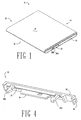
- FIG. 1 shows a portable computer in accordance with embodiments of the invention
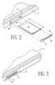
- FIG. 2 shows a portable computer, computer card and bezel in accordance with embodiments of the invention
- Figure 3 shows a computer card and bezel in their installed configuration in accordance with embodiments of the invention.
- Figure 4 shows a bezel in accordance with at least some embodiments of the invention.
- Coupled or “couples” is intended to mean either an indirect or direct connection. Thus, if a first device couples to a second device, that connection may be through a direct connection, or through an indirect connection via other devices and connections.
- FIG 1 illustrates a portable computer 10, which may be, e.g., a notebook or laptop computer.
- the portable computer 10 shown in its closed position, comprises a top housing 12 hingedly coupled to a back 14. Though not specifically shown, the top housing 12 rotates about its hinge to reveal a video screen housed in the top housing 12.
- Portable computer 10 also comprises a first side 18 which is substantially parallel to a second side 20 (not visible in Figure 1). Each of the sides 18 and 20 couple to a bottom housing 22, only a portion of which is visible in the illustration of Figure 1.
- a portable computer in accordance with embodiments of the invention may comprise externally accessible personal computer (PC) card slots 24.
- PC personal computer
- Any existing or after-developed size standards and/or communication protocols may be implemented by the card slots 24.
- At least some embodiments of the invention were developed in the context of Personal Computer Memory Card International Association (PCMCIA) slots, and thus the remaining disclosure discussion is based on card slots having this form factor and using any applicable communication protocol association with the PCMCIA standard.
- PCMCIA slots is merely exemplary, and should not be construed as a required element of any of the embodiments of the invention.
- Figure 1 illustrates two exemplary PCMCIA slots 24, each capable of accepting one PCMCIA standard compliant PC card (cards not specifically shown in Figure 1).
- PCMCIA slots in accordance with embodiments of the invention may utilize a mechanically operated ejection mechanism (not specifically shown in Figure 1) that is actuated by one or more ejection actuation mechanisms 26A and 26B.
- Some PCMCIA cards that mechanically and electrically couple within one of the PCMCIA slots 24 may leave no, or at least an insignificant, portion of the card extending beyond the plane defined by the side 18. Thus, it may be necessary for an operator b push the ejection actuation mechanism 26A/B to at least partially eject the PCMCIA card from the portable computer 10 for removal.
- Some portable computer purchasers may require smart card reading technology to perform tasks such as user authentication prior to booting of the portable computer, e.g., by having the smart card reader verify the user's identity by reading information from a user held smart card.
- some embodiments of the invention may utilize a PCMCIA-based smart card reader in combination with the computer system 10.
- the PCMCIA-based smart card reader may electrically and mechanically couple into one of the PCMCIA slots 24.
- FIG. 2 illustrates various embodiments of the invention which at least partially address these goals.
- Figure 2 illustrates in exploded view the PCMCIA slots 24, an exemplary PCMCIA card 28 to be plugged into one of PCMCIA slots 24, and a bezel 30, in accordance with at least some embodiments of the invention.
- the PCMCIA card 28, which in some embodiments may be a PCMCIA-based smart card reader, can be inserted into the one of the PCMCIA slots 24.
- the card reader 28 has electrical connectors 29 on a first end that electrically couple electronic devices within the card body to electronic devices of the portable computer 10. Either prior to or after insertion of the card reader 28, a bezel 30 is mechanically coupled to at least the card reader 28 at an end opposite the electrical connectors 29.
- An aperture 32 enables the insertion of a smart card through the bezel 30 and into the card reader 28 to electrically couple to the smart card reading mechanism.
- the bezel 30 in accordance with embodiments of the invention may also comprise an extension portion 34. As illustrated in Figure 2, the extension portion 34 at least partially covers the ejection actuation mechanism 26A. Thus, once the card reader 28 and bezel 30 are in place, it is more difficult for a computer system user to remove the card reader 28, as the removal procedure of pushing the ejection actuation mechanism may not be possible, or is at least less readily apparent.
- ejection actuation mechanisms 26 may comprise a plastic button portion that mechanically couples to other mechanical components that provide the ejection functionality. Because the bezel 30, when installed, may be substantially coplanar with the side 18, the plastic button may need to be removed prior to installation of the bezel.
- the card reader 28 may have a slightly shorter length L than a standard PCMCIA-based card. In particular, the PCMCIA standard length for a card is 85.6 mm. In accordance with embodiments of the invention, a card reader 28 may be slightly shorter, for example on the order of 80 mm, such that with the addition of the bezel 30 at least a portion of the front face of the bezel and the side 18 are substantially coplanar.
- Figure 3 illustrates the portable computer 10 after insertion of the card reader 28 and coupling of the bezel 30 to the card reader 28 and/or the portable computer 10.
- a card reader 28 and its corresponding bezel 30 occupies one of the slots, and the extension portion 34 of the bezel 30 hides or makes inaccessible the respective ejection actuation mechanism.
- the card reader 28 and bezel 30 become a semi-permanent fixture of the portable 10, appearing permanent to the average computer system user.
- the exemplary card reader 28 is a smart card reader used as a boot verification device, a user may insert his or her smart card through the aperture 32 just prior to or during the boot process, thus enabling the reader to communicate with the smart card and verify authorization.
- a smart card reader as a boot authorization is merely exemplary.
- the smart card reader may be used for any currently existing or after-developed purpose, such as online transactions using the smart card for payment, securely providing personal information, and providing public and/or private keys for encrypted communications.
- FIG 4 shows the bezel 30 in greater detail.
- the bezel 30 may couple to the portable computer 10 in one or more ways. ln some embodiments, the bezel 30 may couple to the portable computer by coupling to the card 28. In exemplary embodiments the bezel 30 may couple by way of engaging tabs 36 and tongue 38. ln particular, in order to accept a smart card, a smart card reader may have an upper portion and a lower portion with a gap therebetween for insertion of the smart card. The engaging tabs 36 would thus couple to an upper portion of the card 28, while the tongue 38 would couple to the lower portion (the tabs and tongue coupling location may be reversed without departing from the scope and spirit of the invention).
- bezel 30 may couple to the side 18 ( Figure 2).
- bezel 30 may comprise a protrusion 40 on each end of the bezel (only one protrusion visible in Figure 3).
- the protrusion 40 may form a friction fit with the inside diameter of the PCMCIA slot 24.
- the inside diameter of the PCMCIA slot may have a mating indention for protrusion 40.
- the various embodiments described to this point are based on a PCMCIA-based smart card reader.
- any electronic media reader may be used, including other those fore form factors and/or standards of PC cards.
- the card reader 28 may be a storage media reader capable of accepting and electrically coupling to media devices such as memory sticks.
- the bezel 30, and in particular the aperture 32 may be of different sizes to accommodate insertion of these various storage media.
- the storage media reader may also be a PCMCIA-based reader, with the bezel30 covering the ejection actuation mechanism.
Landscapes
- Engineering & Computer Science (AREA)
- Theoretical Computer Science (AREA)
- Computer Hardware Design (AREA)
- Power Engineering (AREA)
- Human Computer Interaction (AREA)
- Physics & Mathematics (AREA)
- General Engineering & Computer Science (AREA)
- General Physics & Mathematics (AREA)
- Microelectronics & Electronic Packaging (AREA)
- Casings For Electric Apparatus (AREA)
- Conveying Record Carriers (AREA)
- Lock And Its Accessories (AREA)
Abstract
Description
- A smart card is a device similar in size and appearance to a credit card. Smart cards have embedded therein various electronic devices, such as a microcontroller and random access memory. Smart cards can perform a variety of tasks based to some extent on the identity of the user. For example, smart cards may be used to: control access to parking garages and/or buildings; make available and accessible user information such as biometric information and/or personal medical history; hold and provide personal encryption keys for secure communication; authenticate authorization for the holder to boot and/or use a computer system.
- Some computer system purchasers, for example large corporations, demand portable computers, such as laptop or notebook computers, that authenticate the user's authorization prior to allowing the computer system to be used or to boot. Computer system manufacturers have thus implemented smart card reading electronics on the motherboards of portable computers. However, the number of purchasers desiring to use smart card technology in relation to the total number of computers sold is relatively small, and thus the addition of the dedicated smart card reading electronics to the motherboard adds an expense to the computer systems that is not justified in the minds of most consumers.
- To address this problem, some computer system manufacturers may provide smart card reading devices in the form of Personal Computer Memory Card International Association (PCMCIA) standard compliant computer cards that may be plugged into PCMCIA slots on the computer system. However, this method of providing the smart card reading technology may be less desirable in the eyes of the consumer as it appears non-permanent. Moreover, PCMCIA slots may have a card ejection mechanism actuated by a button proximate to the aperture in the computer system housing, and therefore a computer system user may inadvertently remove and lose the smart card reading device, thus making it difficult for the user to utilize the computer system.
- The problems noted above are solved in large part by a system and related method of a computer card slot and a bezel. Some of the exemplary embodiments may be a portable computer comprising a computer card slot accessible through an aperture in a housing of the portable computer, a card reader electrically coupled within the computer card slot, and a bezel mechanically abutting an outer end of the card reader (at least a portion of an outer face of the bezel substantially coplanar with the housing). The computer card slot comprises a computer card ejection actuation mechanism proximate to the aperture in the housing, and wherein the bezel at least partially covers the ejection actuation mechanism.
- For a detailed description of exemplary embodiments of the invention, reference will now be made to the accompanying drawings in which:
- Figure 1 shows a portable computer in accordance with embodiments of the invention;
- Figures 2 shows a portable computer, computer card and bezel in accordance with embodiments of the invention;
- Figure 3 shows a computer card and bezel in their installed configuration in accordance with embodiments of the invention; and
- Figure 4 shows a bezel in accordance with at least some embodiments of the invention.
- Certain terms are used throughout the following description and claims to refer to particular system components. As one skilled in the art will appreciate, computer companies may refer to a component by different names. This document does not intend to distinguish between components that differ in name but not function.
- In the following discussion and in the claims, the terms "including" and "comprising" are used in an open-ended fashion, and thus should be interpreted to mean "including, but not limited to...." Also, the term "couple" or "couples" is intended to mean either an indirect or direct connection. Thus, if a first device couples to a second device, that connection may be through a direct connection, or through an indirect connection via other devices and connections.
- The following discussion is directed to various embodiments of the invention. Although one or more of these embodiments may be preferred, the embodiments disclosed should not be interpreted, or otherwise used, as limiting the scope of the disclosure. In addition, one skilled in the art will understand that the following description has broad application, and the discussion of any embodiment is meant only to be exemplary of that embodiment, and not intended to intimate that the scope of the disclosure is limited to that embodiment.
- Figure 1 illustrates a
portable computer 10, which may be, e.g., a notebook or laptop computer. Theportable computer 10, shown in its closed position, comprises atop housing 12 hingedly coupled to aback 14. Though not specifically shown, thetop housing 12 rotates about its hinge to reveal a video screen housed in thetop housing 12.Portable computer 10 also comprises afirst side 18 which is substantially parallel to a second side 20 (not visible in Figure 1). Each of thesides bottom housing 22, only a portion of which is visible in the illustration of Figure 1. - A portable computer in accordance with embodiments of the invention may comprise externally accessible personal computer (PC)
card slots 24. Any existing or after-developed size standards and/or communication protocols may be implemented by thecard slots 24. At least some embodiments of the invention were developed in the context of Personal Computer Memory Card International Association (PCMCIA) slots, and thus the remaining disclosure discussion is based on card slots having this form factor and using any applicable communication protocol association with the PCMCIA standard. However, use of PCMCIA slots is merely exemplary, and should not be construed as a required element of any of the embodiments of the invention. Particularly, Figure 1 illustrates twoexemplary PCMCIA slots 24, each capable of accepting one PCMCIA standard compliant PC card (cards not specifically shown in Figure 1). - PCMCIA slots in accordance with embodiments of the invention may utilize a mechanically operated ejection mechanism (not specifically shown in Figure 1) that is actuated by one or more
ejection actuation mechanisms PCMCIA slots 24 may leave no, or at least an insignificant, portion of the card extending beyond the plane defined by theside 18. Thus, it may be necessary for an operator b push theejection actuation mechanism 26A/B to at least partially eject the PCMCIA card from theportable computer 10 for removal. - Some portable computer purchasers may require smart card reading technology to perform tasks such as user authentication prior to booting of the portable computer, e.g., by having the smart card reader verify the user's identity by reading information from a user held smart card. In order to provide the smart card functionality without the necessity of implementing the smart card electronics on the computer system motherboard, some embodiments of the invention may utilize a PCMCIA-based smart card reader in combination with the
computer system 10. The PCMCIA-based smart card reader may electrically and mechanically couple into one of the PCMCIAslots 24. However, it may be desirable to give the appearance to the end user that the smart card reader is a permanent fixture of theportable computer 10, and further it may be desirable to make it difficult for the computer system user to inadvertently remove the PCMCIA-based smart card reader from theportable computer 10. Figure 2 illustrates various embodiments of the invention which at least partially address these goals. - In particular, Figure 2 illustrates in exploded view the PCMCIA
slots 24, an exemplary PCMCIAcard 28 to be plugged into one ofPCMCIA slots 24, and abezel 30, in accordance with at least some embodiments of the invention. The PCMCIAcard 28, which in some embodiments may be a PCMCIA-based smart card reader, can be inserted into the one of the PCMCIAslots 24. Thecard reader 28 haselectrical connectors 29 on a first end that electrically couple electronic devices within the card body to electronic devices of theportable computer 10. Either prior to or after insertion of thecard reader 28, abezel 30 is mechanically coupled to at least thecard reader 28 at an end opposite theelectrical connectors 29. Anaperture 32 enables the insertion of a smart card through thebezel 30 and into thecard reader 28 to electrically couple to the smart card reading mechanism. - The
bezel 30 in accordance with embodiments of the invention may also comprise anextension portion 34. As illustrated in Figure 2, theextension portion 34 at least partially covers theejection actuation mechanism 26A. Thus, once thecard reader 28 andbezel 30 are in place, it is more difficult for a computer system user to remove thecard reader 28, as the removal procedure of pushing the ejection actuation mechanism may not be possible, or is at least less readily apparent. - In at least some embodiments of the invention, ejection actuation mechanisms 26 may comprise a plastic button portion that mechanically couples to other mechanical components that provide the ejection functionality. Because the
bezel 30, when installed, may be substantially coplanar with theside 18, the plastic button may need to be removed prior to installation of the bezel. To this same end, thecard reader 28 may have a slightly shorter length L than a standard PCMCIA-based card. In particular, the PCMCIA standard length for a card is 85.6 mm. In accordance with embodiments of the invention, acard reader 28 may be slightly shorter, for example on the order of 80 mm, such that with the addition of thebezel 30 at least a portion of the front face of the bezel and theside 18 are substantially coplanar. - Figure 3 illustrates the
portable computer 10 after insertion of thecard reader 28 and coupling of thebezel 30 to thecard reader 28 and/or theportable computer 10. As can be seen, only once card reader and respective bezel are in place within one of the two illustrated PCMCIAslots 24. After insertion, acard reader 28 and its correspondingbezel 30 occupies one of the slots, and theextension portion 34 of thebezel 30 hides or makes inaccessible the respective ejection actuation mechanism. Thus, once installed thecard reader 28 andbezel 30 become a semi-permanent fixture of the portable 10, appearing permanent to the average computer system user. If theexemplary card reader 28 is a smart card reader used as a boot verification device, a user may insert his or her smart card through theaperture 32 just prior to or during the boot process, thus enabling the reader to communicate with the smart card and verify authorization. Using a smart card reader as a boot authorization is merely exemplary. The smart card reader may be used for any currently existing or after-developed purpose, such as online transactions using the smart card for payment, securely providing personal information, and providing public and/or private keys for encrypted communications. - Figure 4 shows the
bezel 30 in greater detail. Thebezel 30 may couple to theportable computer 10 in one or more ways. ln some embodiments, thebezel 30 may couple to the portable computer by coupling to thecard 28. In exemplary embodiments thebezel 30 may couple by way of engaging tabs 36 andtongue 38. ln particular, in order to accept a smart card, a smart card reader may have an upper portion and a lower portion with a gap therebetween for insertion of the smart card. The engaging tabs 36 would thus couple to an upper portion of thecard 28, while thetongue 38 would couple to the lower portion (the tabs and tongue coupling location may be reversed without departing from the scope and spirit of the invention). In addition to, or in place of, coupling directly to thecard 28, thebezel 30 may couple to the side 18 (Figure 2). In particular,bezel 30 may comprise aprotrusion 40 on each end of the bezel (only one protrusion visible in Figure 3). Theprotrusion 40 may form a friction fit with the inside diameter of thePCMCIA slot 24. Alternatively, the inside diameter of the PCMCIA slot may have a mating indention forprotrusion 40. - The various embodiments described to this point are based on a PCMCIA-based smart card reader. However, in alternative embodiments of the invention any electronic media reader may be used, including other those fore form factors and/or standards of PC cards. For example, the
card reader 28 may be a storage media reader capable of accepting and electrically coupling to media devices such as memory sticks. In these embodiments, thebezel 30, and in particular theaperture 32, may be of different sizes to accommodate insertion of these various storage media. Moreover, the storage media reader may also be a PCMCIA-based reader, with the bezel30 covering the ejection actuation mechanism.
Claims (10)
- A portable computer (10) comprising:a computer card slot (24) accessible through an aperture in a housing (18) of the portable computer (10);a card reader (28) electrically coupled within the computer card slot (24); anda bezel (30) mechanically abutting an outer end of the card reader (28), at least a portion of an outer face of the bezel (30) substantially coplanar with the housing (18);wherein the computer card slot (24) comprises a computer card ejection actuation mechanism (26) proximate to the aperture in the housing (18), and wherein the bezel (30) at least partially covers the ejection actuation mechanism (26).
- The portable computer (10) as defined in claim 1 wherein the bezel (30) fully covers the ejection actuation mechanism (26).
- The portable computer (10) as defined in claim 1 wherein the card reader (28) further comprises a smart card reader, and wherein the bezel (30) further comprises an aperture (32) enabling insertion of a smart card through the bezel to electrically couple to the smart card reader (28).
- The portable computer (10) as defined in claim 1 wherein the card reader (28) further comprises a storage media reader, and wherein the bezel (30) further comprises an aperture (32) enabling insertion of a storage media through the bezel to electrically couple to the media reader.
- The portable computer as defined in claim 1 wherein the computer card slot is a Personal Computer Memory Card International Association (PCMCIA) compliant card slot, and wherein the computer card is PCMCIA compliant.
- A card reader (28) comprising:electrical connectors (29) on a first end of a card body, the electrical connectors (29) electrically couple electronic devices at least partially within the card body to electronic devices of a computer system (10); anda bezel (30) on a second end of the card body opposite the first end, a plane defined by a front face of the bezel (30) substantially perpendicular to a plane defined by a length and width of the card body;wherein the bezel (30) comprises an extension portion (34) at least partially within the plane defined by the front face, wherein when the card reader (28) is installed in a computer system (10) the extension portion (34) at least partially hides a card ejection actuation mechanism (26).
- The card reader (28) as defined in claim 6 wherein the bezel (30) further comprises an aperture (32) that enables insertion of devices at least partially within the card body.
- The card reader (28) as defined in claim 6 wherein the card reader (28) is a Personal Computer Memory Card International Association (PCMCIA) standard compliant computer card.
- The card reader (28) as defined in claim 6 wherein the card reader (28) is smart card reader.
- The card reader (28) as defined in claim 6 wherein the card reader (28) is a storage media reader.
Applications Claiming Priority (1)
| Application Number | Priority Date | Filing Date | Title |
|---|---|---|---|
| US10/942,465 US7309016B2 (en) | 2004-09-16 | 2004-09-16 | System and method of a computer card slot and bezel |
Publications (3)
| Publication Number | Publication Date |
|---|---|
| EP1638382A2 true EP1638382A2 (en) | 2006-03-22 |
| EP1638382A3 EP1638382A3 (en) | 2008-07-30 |
| EP1638382B1 EP1638382B1 (en) | 2011-05-11 |
Family
ID=35636951
Family Applications (1)
| Application Number | Title | Priority Date | Filing Date |
|---|---|---|---|
| EP05017903A Ceased EP1638382B1 (en) | 2004-09-16 | 2005-08-17 | System and method of a computer card slot and bezel |
Country Status (4)
| Country | Link |
|---|---|
| US (1) | US7309016B2 (en) |
| EP (1) | EP1638382B1 (en) |
| JP (1) | JP4129015B2 (en) |
| CN (1) | CN100573407C (en) |
Cited By (1)
| Publication number | Priority date | Publication date | Assignee | Title |
|---|---|---|---|---|
| EP3139311A1 (en) * | 2015-08-31 | 2017-03-08 | Goodrich Corporation | Shield member for selectively securing an electrical device |
Families Citing this family (18)
| Publication number | Priority date | Publication date | Assignee | Title |
|---|---|---|---|---|
| CN201515407U (en) * | 2009-09-04 | 2010-06-23 | 深圳富泰宏精密工业有限公司 | Protective cover and portable electronic device with the same |
| CN201515088U (en) * | 2009-09-14 | 2010-06-23 | 深圳富泰宏精密工业有限公司 | Connector cover body structure and electronic device provided with the connector cover body structure |
| TW201111952A (en) * | 2009-09-25 | 2011-04-01 | Pegatron Corp | Computer |
| KR101880181B1 (en) * | 2011-07-21 | 2018-07-19 | 삼성전자주식회사 | Insert type card retracting/extending apparatus for electronic device |
| CN102427184B (en) * | 2011-08-18 | 2013-12-11 | 鸿富锦精密工业(深圳)有限公司 | Electronic device having ejection mechanism |
| TWI462025B (en) * | 2011-11-30 | 2014-11-21 | Wistron Corp | Card reader having movable card insertion mechanism and electronic device |
| KR101264562B1 (en) * | 2011-12-19 | 2013-05-14 | 에스케이씨앤씨 주식회사 | Tray integrated smart card and mobile device using the same |
| CN103515777A (en) * | 2012-06-18 | 2014-01-15 | 深圳富泰宏精密工业有限公司 | Chip card holding structure and electronic device having the same |
| US9128675B2 (en) * | 2013-03-06 | 2015-09-08 | Panasonic Intellectual Property Management Co., Ltd. | Electronic device |
| US9236681B2 (en) * | 2014-03-21 | 2016-01-12 | Cheng Uei Precision Industry Co., Ltd. | Card connector |
| CN104004921B (en) | 2014-05-31 | 2016-03-02 | 北京工业大学 | A kind of solvent extration efficiently concentrating reclaims the technique of noble metal platinum, palladium |
| CN106207578B (en) * | 2015-05-07 | 2020-09-01 | 中兴通讯股份有限公司 | Trays and Electronic Devices |
| KR102501571B1 (en) * | 2016-02-12 | 2023-02-21 | 삼성전자 주식회사 | Apparatus for use in a key of electronic device |
| US10832101B2 (en) | 2016-07-29 | 2020-11-10 | Hewlett-Packard Development Company, L.P. | Electronic card holders |
| CN107681345B (en) * | 2016-08-01 | 2021-03-23 | 东莞莫仕连接器有限公司 | Electrical connector assembly |
| WO2018026377A1 (en) * | 2016-08-05 | 2018-02-08 | Hewlett-Packard Development Company, L.P. | Stylus retaining assembly |
| CN107562140B (en) * | 2017-09-08 | 2018-08-03 | 广东三人行管理咨询股份有限公司 | A miniature high-capacity information memory |
| US11003613B2 (en) * | 2019-09-23 | 2021-05-11 | Dell Products L.P. | Eject pull mechanism for information handling system |
Citations (3)
| Publication number | Priority date | Publication date | Assignee | Title |
|---|---|---|---|---|
| US6125034A (en) | 1997-03-21 | 2000-09-26 | Digital Equipment Corporation | Computer having internally mounted peripheral devices with moveable adapter |
| US6460772B1 (en) | 1998-09-01 | 2002-10-08 | Intertex Data Ab | PCMCIA smart card reader |
| US6491226B1 (en) | 1998-08-24 | 2002-12-10 | Nec Infrontia Corporation | Method and apparatus for preventing extraction of card-shaped functional device for information processing apparatus, and recording medium storing program for realizing extraction preventing operation on computer |
Family Cites Families (10)
| Publication number | Priority date | Publication date | Assignee | Title |
|---|---|---|---|---|
| JP3529394B2 (en) * | 1992-10-19 | 2004-05-24 | 株式会社東芝 | IC card information processing device |
| US5470241A (en) * | 1993-12-21 | 1995-11-28 | The Whitaker Corporation | Retention mechanism for memory cards |
| US5625534A (en) * | 1995-05-12 | 1997-04-29 | Dell Computer Corporation | Portable computer having a data card reader apparatus associated therewith |
| US5752857A (en) | 1996-05-24 | 1998-05-19 | Itt Corporation | Smart card computer adaptor |
| US6015092A (en) | 1998-02-05 | 2000-01-18 | Postlewaite; William M. | Smart card reader having angled smart card holder |
| US6234389B1 (en) | 1998-04-29 | 2001-05-22 | @Pos.Com, Inc. | PCMCIA-based point of sale transaction system |
| GB2338811B (en) * | 1998-06-26 | 2002-10-02 | Nokia Mobile Phones Ltd | A cardholder |
| US6371376B1 (en) | 1999-04-16 | 2002-04-16 | Ho J. Dan | PCMCIA card with secure smart card reader |
| US6641034B1 (en) * | 2000-08-11 | 2003-11-04 | Matsushita Electric Industrial Co., Ltd. | Card reader with a light-emitting bezel |
| WO2003073246A1 (en) * | 2002-02-26 | 2003-09-04 | Fujitsu Limited | Electronic apparatus and function extension device for extending function of electronic apparatus |
-
2004
- 2004-09-16 US US10/942,465 patent/US7309016B2/en not_active Expired - Lifetime
-
2005
- 2005-08-17 EP EP05017903A patent/EP1638382B1/en not_active Ceased
- 2005-08-29 JP JP2005247312A patent/JP4129015B2/en not_active Expired - Fee Related
- 2005-09-16 CN CNB2005101038914A patent/CN100573407C/en not_active Expired - Fee Related
Patent Citations (3)
| Publication number | Priority date | Publication date | Assignee | Title |
|---|---|---|---|---|
| US6125034A (en) | 1997-03-21 | 2000-09-26 | Digital Equipment Corporation | Computer having internally mounted peripheral devices with moveable adapter |
| US6491226B1 (en) | 1998-08-24 | 2002-12-10 | Nec Infrontia Corporation | Method and apparatus for preventing extraction of card-shaped functional device for information processing apparatus, and recording medium storing program for realizing extraction preventing operation on computer |
| US6460772B1 (en) | 1998-09-01 | 2002-10-08 | Intertex Data Ab | PCMCIA smart card reader |
Cited By (2)
| Publication number | Priority date | Publication date | Assignee | Title |
|---|---|---|---|---|
| EP3139311A1 (en) * | 2015-08-31 | 2017-03-08 | Goodrich Corporation | Shield member for selectively securing an electrical device |
| US9635770B2 (en) | 2015-08-31 | 2017-04-25 | Goodrich Corporation | Shield member for selectively securing an electrical device |
Also Published As
| Publication number | Publication date |
|---|---|
| JP4129015B2 (en) | 2008-07-30 |
| US20060054698A1 (en) | 2006-03-16 |
| CN100573407C (en) | 2009-12-23 |
| CN1749921A (en) | 2006-03-22 |
| US7309016B2 (en) | 2007-12-18 |
| EP1638382A3 (en) | 2008-07-30 |
| EP1638382B1 (en) | 2011-05-11 |
| JP2006085690A (en) | 2006-03-30 |
Similar Documents
| Publication | Publication Date | Title |
|---|---|---|
| US7309016B2 (en) | System and method of a computer card slot and bezel | |
| JP2593836B2 (en) | Insertable memory card for microcomputer with contacts connected to access card and system thereof | |
| US6748541B1 (en) | User-computer interaction method for use by a population of flexibly connectable computer systems | |
| JP4758527B2 (en) | Method and apparatus for interaction between user and computer | |
| KR100842484B1 (en) | Contact and contactless smart card terminals and terminal circuits | |
| HK1042144A1 (en) | Portable electronic charge and authorization devices and methods therefor | |
| KR20080039330A (en) | Display input device for contact and contactless smart card terminal and electronic circuit applied thereto | |
| US6058089A (en) | External floppy drive with secure storage of a cable and connector for connecting to a computer system | |
| US7364439B2 (en) | Memory card assembly | |
| JPH08123917A (en) | IC card and IC card system | |
| US7184274B2 (en) | Flash memory encryption device | |
| US6390855B1 (en) | Expansion slot adapter for a palm held computer | |
| JP2003150912A (en) | Smart card adapter | |
| KR100872046B1 (en) | Card Type USB Memory Device | |
| CN108649359A (en) | Card insertion device and electronic equipment | |
| JP2002522852A (en) | Security system | |
| KR100984137B1 (en) | Card type USB device | |
| US20050114584A1 (en) | Multimedia access device | |
| US20030168511A1 (en) | Card reader system for installed in a personal computer | |
| GB2427047A (en) | Smartcard having a USB plug | |
| KR100625513B1 (en) | Wallet Smart Card Reader | |
| KR200195389Y1 (en) | Ic card having contact lead in the border | |
| WO2008004214A2 (en) | Electrical adapter for coupling to a portable card and a portable card integral with such an adapter | |
| JP2005346263A (en) | Storage system and storage method | |
| CN121585752A (en) | mobile device |
Legal Events
| Date | Code | Title | Description |
|---|---|---|---|
| PUAI | Public reference made under article 153(3) epc to a published international application that has entered the european phase |
Free format text: ORIGINAL CODE: 0009012 |
|
| AK | Designated contracting states |
Kind code of ref document: A2 Designated state(s): AT BE BG CH CY CZ DE DK EE ES FI FR GB GR HU IE IS IT LI LT LU LV MC NL PL PT RO SE SI SK TR |
|
| AX | Request for extension of the european patent |
Extension state: AL BA HR MK YU |
|
| PUAL | Search report despatched |
Free format text: ORIGINAL CODE: 0009013 |
|
| AK | Designated contracting states |
Kind code of ref document: A3 Designated state(s): AT BE BG CH CY CZ DE DK EE ES FI FR GB GR HU IE IS IT LI LT LU LV MC NL PL PT RO SE SI SK TR |
|
| AX | Request for extension of the european patent |
Extension state: AL BA HR MK YU |
|
| RIC1 | Information provided on ipc code assigned before grant |
Ipc: H05K 5/02 20060101AFI20060131BHEP Ipc: G06K 7/00 20060101ALI20080625BHEP Ipc: G06F 1/16 20060101ALI20080625BHEP |
|
| 17P | Request for examination filed |
Effective date: 20081118 |
|
| AKX | Designation fees paid |
Designated state(s): DE GB |
|
| GRAP | Despatch of communication of intention to grant a patent |
Free format text: ORIGINAL CODE: EPIDOSNIGR1 |
|
| GRAS | Grant fee paid |
Free format text: ORIGINAL CODE: EPIDOSNIGR3 |
|
| GRAA | (expected) grant |
Free format text: ORIGINAL CODE: 0009210 |
|
| AK | Designated contracting states |
Kind code of ref document: B1 Designated state(s): DE GB |
|
| REG | Reference to a national code |
Ref country code: GB Ref legal event code: FG4D |
|
| REG | Reference to a national code |
Ref country code: DE Ref legal event code: R096 Ref document number: 602005027941 Country of ref document: DE Effective date: 20110622 |
|
| PLBE | No opposition filed within time limit |
Free format text: ORIGINAL CODE: 0009261 |
|
| STAA | Information on the status of an ep patent application or granted ep patent |
Free format text: STATUS: NO OPPOSITION FILED WITHIN TIME LIMIT |
|
| 26N | No opposition filed |
Effective date: 20120214 |
|
| REG | Reference to a national code |
Ref country code: DE Ref legal event code: R097 Ref document number: 602005027941 Country of ref document: DE Effective date: 20120214 |
|
| PGFP | Annual fee paid to national office [announced via postgrant information from national office to epo] |
Ref country code: DE Payment date: 20180719 Year of fee payment: 14 |
|
| PGFP | Annual fee paid to national office [announced via postgrant information from national office to epo] |
Ref country code: GB Payment date: 20180720 Year of fee payment: 14 |
|
| REG | Reference to a national code |
Ref country code: DE Ref legal event code: R119 Ref document number: 602005027941 Country of ref document: DE |
|
| GBPC | Gb: european patent ceased through non-payment of renewal fee |
Effective date: 20190817 |
|
| PG25 | Lapsed in a contracting state [announced via postgrant information from national office to epo] |
Ref country code: DE Free format text: LAPSE BECAUSE OF NON-PAYMENT OF DUE FEES Effective date: 20200303 |
|
| PG25 | Lapsed in a contracting state [announced via postgrant information from national office to epo] |
Ref country code: GB Free format text: LAPSE BECAUSE OF NON-PAYMENT OF DUE FEES Effective date: 20190817 |