EP1638163A1 - Electronic device - Google Patents
Electronic device Download PDFInfo
- Publication number
- EP1638163A1 EP1638163A1 EP03705149A EP03705149A EP1638163A1 EP 1638163 A1 EP1638163 A1 EP 1638163A1 EP 03705149 A EP03705149 A EP 03705149A EP 03705149 A EP03705149 A EP 03705149A EP 1638163 A1 EP1638163 A1 EP 1638163A1
- Authority
- EP
- European Patent Office
- Prior art keywords
- antenna
- dielectric material
- electronic apparatus
- movement mechanism
- move
- Prior art date
- Legal status (The legal status is an assumption and is not a legal conclusion. Google has not performed a legal analysis and makes no representation as to the accuracy of the status listed.)
- Withdrawn
Links
Images



Classifications
-
- H—ELECTRICITY
- H01—ELECTRIC ELEMENTS
- H01Q—ANTENNAS, i.e. RADIO AERIALS
- H01Q13/00—Waveguide horns or mouths; Slot antennas; Leaky-waveguide antennas; Equivalent structures causing radiation along the transmission path of a guided wave
- H01Q13/10—Resonant slot antennas
-
- G—PHYSICS
- G06—COMPUTING OR CALCULATING; COUNTING
- G06F—ELECTRIC DIGITAL DATA PROCESSING
- G06F1/00—Details not covered by groups G06F3/00 - G06F13/00 and G06F21/00
- G06F1/16—Constructional details or arrangements
- G06F1/1613—Constructional details or arrangements for portable computers
- G06F1/1615—Constructional details or arrangements for portable computers with several enclosures having relative motions, each enclosure supporting at least one I/O or computing function
- G06F1/1616—Constructional details or arrangements for portable computers with several enclosures having relative motions, each enclosure supporting at least one I/O or computing function with folding flat displays, e.g. laptop computers or notebooks having a clamshell configuration, with body parts pivoting to an open position around an axis parallel to the plane they define in closed position
-
- G—PHYSICS
- G06—COMPUTING OR CALCULATING; COUNTING
- G06F—ELECTRIC DIGITAL DATA PROCESSING
- G06F1/00—Details not covered by groups G06F3/00 - G06F13/00 and G06F21/00
- G06F1/16—Constructional details or arrangements
- G06F1/1613—Constructional details or arrangements for portable computers
- G06F1/1633—Constructional details or arrangements of portable computers not specific to the type of enclosures covered by groups G06F1/1615 - G06F1/1626
- G06F1/1637—Details related to the display arrangement, including those related to the mounting of the display in the housing
-
- G—PHYSICS
- G06—COMPUTING OR CALCULATING; COUNTING
- G06F—ELECTRIC DIGITAL DATA PROCESSING
- G06F1/00—Details not covered by groups G06F3/00 - G06F13/00 and G06F21/00
- G06F1/16—Constructional details or arrangements
- G06F1/1613—Constructional details or arrangements for portable computers
- G06F1/1633—Constructional details or arrangements of portable computers not specific to the type of enclosures covered by groups G06F1/1615 - G06F1/1626
- G06F1/1684—Constructional details or arrangements related to integrated I/O peripherals not covered by groups G06F1/1635 - G06F1/1675
- G06F1/1698—Constructional details or arrangements related to integrated I/O peripherals not covered by groups G06F1/1635 - G06F1/1675 the I/O peripheral being a sending/receiving arrangement to establish a cordless communication link, e.g. radio or infrared link, integrated cellular phone
-
- H—ELECTRICITY
- H01—ELECTRIC ELEMENTS
- H01Q—ANTENNAS, i.e. RADIO AERIALS
- H01Q1/00—Details of, or arrangements associated with, antennas
- H01Q1/12—Supports; Mounting means
- H01Q1/22—Supports; Mounting means by structural association with other equipment or articles
- H01Q1/2258—Supports; Mounting means by structural association with other equipment or articles used with computer equipment
- H01Q1/2266—Supports; Mounting means by structural association with other equipment or articles used with computer equipment disposed inside the computer
-
- H—ELECTRICITY
- H01—ELECTRIC ELEMENTS
- H01Q—ANTENNAS, i.e. RADIO AERIALS
- H01Q1/00—Details of, or arrangements associated with, antennas
- H01Q1/12—Supports; Mounting means
- H01Q1/22—Supports; Mounting means by structural association with other equipment or articles
- H01Q1/24—Supports; Mounting means by structural association with other equipment or articles with receiving set
- H01Q1/241—Supports; Mounting means by structural association with other equipment or articles with receiving set used in mobile communications, e.g. GSM
- H01Q1/242—Supports; Mounting means by structural association with other equipment or articles with receiving set used in mobile communications, e.g. GSM specially adapted for hand-held use
- H01Q1/243—Supports; Mounting means by structural association with other equipment or articles with receiving set used in mobile communications, e.g. GSM specially adapted for hand-held use with built-in antennas
-
- H—ELECTRICITY
- H01—ELECTRIC ELEMENTS
- H01Q—ANTENNAS, i.e. RADIO AERIALS
- H01Q9/00—Electrically-short antennas having dimensions not more than twice the operating wavelength and consisting of conductive active radiating elements
- H01Q9/04—Resonant antennas
- H01Q9/0407—Substantially flat resonant element parallel to ground plane, e.g. patch antenna
- H01Q9/0421—Substantially flat resonant element parallel to ground plane, e.g. patch antenna with a shorting wall or a shorting pin at one end of the element
-
- H—ELECTRICITY
- H01—ELECTRIC ELEMENTS
- H01Q—ANTENNAS, i.e. RADIO AERIALS
- H01Q9/00—Electrically-short antennas having dimensions not more than twice the operating wavelength and consisting of conductive active radiating elements
- H01Q9/04—Resonant antennas
- H01Q9/0407—Substantially flat resonant element parallel to ground plane, e.g. patch antenna
- H01Q9/0442—Substantially flat resonant element parallel to ground plane, e.g. patch antenna with particular tuning means
-
- H—ELECTRICITY
- H01—ELECTRIC ELEMENTS
- H01Q—ANTENNAS, i.e. RADIO AERIALS
- H01Q9/00—Electrically-short antennas having dimensions not more than twice the operating wavelength and consisting of conductive active radiating elements
- H01Q9/04—Resonant antennas
- H01Q9/06—Details
- H01Q9/14—Length of element or elements adjustable
-
- H—ELECTRICITY
- H01—ELECTRIC ELEMENTS
- H01Q—ANTENNAS, i.e. RADIO AERIALS
- H01Q9/00—Electrically-short antennas having dimensions not more than twice the operating wavelength and consisting of conductive active radiating elements
- H01Q9/04—Resonant antennas
- H01Q9/30—Resonant antennas with feed to end of elongated active element, e.g. unipole
- H01Q9/42—Resonant antennas with feed to end of elongated active element, e.g. unipole with folded element, the folded parts being spaced apart a small fraction of the operating wavelength
Definitions
- the present invention relates to an electronic apparatus including an antenna for radio communication.
- radio communication systems such as a radio LAN and Bluetooth (R)
- radio waves for example, of a 2.5 GHz or 5 GHz band are used.
- antennas for radio communication various antennas such as a dipole antenna, helical antenna, slot antenna, and inverted F-shaped antenna are used for each type of the apparatus.
- a resonance frequency of the antenna is determined by shape, size, and peripheral environment of the antenna. Usually, a certain resonance frequency band is allocated to one antenna. Therefore, when a plurality of radio modules different in frequency band from one another are used, a plurality of antennas have to be installed for these respective radio modules, and a problem of installation space occurs.
- the resonance frequency which can structurally be covered by one antenna, and with a predetermined number of (e.g., three) or more frequencies, there are disadvantages that the antenna size becomes very large and that the shape also becomes complicated. Furthermore, when a plurality of resonance frequencies are assigned to one antenna, there is a disadvantage that a usable band is narrowed.
- An object of the present invention is to provide an electronic apparatus in which a resonance frequency of an antenna can appropriately be switched for each radio module without improving a shape of the antenna.
- an electronic apparatus comprising: a plurality of radio modules different in frequency band from one another; an antenna for use in common to the respective radio modules; a dielectric material disposed in the vicinity of the antenna; a movement mechanism to support the dielectric material so that the dielectric material can move with respect to the antenna; and switch means for adjusting an interval between the antenna and dielectric material by the movement mechanism to switch the resonance frequency of the antenna for each of the radio modules.
- the resonance frequency of the antenna can be switched for each of the respective radio modules.
- FIG. 1 is a perspective view showing an appearance constitution of an electronic apparatus in a first embodiment of the present invention. It is to be noted that here a portable personal computer (hereinafter abbreviated as PC) is described as an example of the electronic apparatus.
- PC portable personal computer
- a plurality of radio modules 10a, 10b, 10c, ... are mounted which are for use in radio communication and which are different in frequency band from one another.
- a user can selectively use one of these radio modules 10a, 10b, 10c, ... to perform the radio communication. It is to be noted that there are the following types of radio communications:
- IEEE802.11b and IEEE802.11a are communication standards of the radio LAN determined by an "IEEE802.11" working group.
- Bluetooth(R) is the communication standard of a short-distance radio communication system.
- the PDC, GSM, IS-136, and CdmaOne(R) are the communication standards of a mobile radio communication system.
- radio modules radio equipments
- the PC 1 includes a main body case 2, display portion case 3, LCD panel 4, and keyboard 5.
- the keyboard 5 is disposed in an upper surface portion of the main body case 2.
- the main body case 2 and the display case 3 are rotatably connected to each other via hinge portions 6.
- the display portion case 3 supports a peripheral portion of the LCD panel 4 so that a display region of the LCD panel 4 is brought in a visible state.
- the display portion case 3 can rotate in an arrow a1-a2 direction via the hinge portions 6. That is, this display portion case 3 can rotate between a closed position in which the keyboard 5 is covered and an opened position in which the keyboard 5 is brought into a usable state.
- the main body case 2 and display portion case 3 are formed by dielectric materials such as a synthetic resin.
- an antenna for radio communication 7 for use, for example, in the radio LAN (IEEE802.11b) is disposed in the display portion case 3.
- IEEE802.11b a direct sequence spread spectrum (DSSS) is used which is one of the radio communication standards using an industry science medical (ISM) band of a 2.4 GHz band and which is a spread spectrum system, and communication is possible at a communication rate of 11 Mbps at maximum.
- ISM industry science medical
- the antenna 7 is disposed in a high position in order to improve a reception sensitivity.
- the antenna 7 of a flat plate type is disposed in an upper part of the display portion case 3, which corresponds to the high position at a use time. This antenna 7 is used in common to the respective radio modules 10a, 10b, 10c, ... mounted on the PC 1.
- an inverted F-shaped antenna shown in FIG. 2 is used.
- a rectangular antenna substrate 11 is used, a groove 12 is disposed along an upper side of the substrate to form an element 13 which is a radio wave radiation element in the upper side of the antenna substrate 11, and another region is formed as a ground (GND) 14.
- a power supply point 15 is disposed in a position near a base portion. In this case, the position of the power supply point 15 is set so that an impedance in the point indicates, for example, 50 ⁇ .
- a metal plate having a thickness, for example, of about 0.1 mm is used, and the opposite surfaces of the substrate are laminate-treated and protected.
- a width W of the antenna substrate 11 is set substantially to a 1/4 wavelength ( ⁇ ) of the wavelength ( ⁇ ) of a desired frequency.
- a concrete size of the antenna substrate 11 is about 30 X 30 mm, for example, when radio waves of a 2.4 GHz band are used.
- the groove 12 has a width of about 2 mm
- the element 13 has a width of about 1 mm.
- a rectangular dielectric material 8 formed, for example, by a synthetic resin is disposed so as to be movable in a vertical direction with respect to one plane side of the antenna 7.
- a resonance frequency of the antenna 7 is determined in accordance with the length of D.
- FIG. 3 is a sectional side view showing a state in which the inverted F-shaped antenna 7 is actually mounted on the display portion case 3.
- the antenna 7 is fixed to the upper portion of the display portion case 3 using adhesives.
- the antenna 7 is disposed while a side with the element 13 formed thereon is projected upwards from the upper end of the LCD panel 4 by a predetermined width (e.g., about 5 to 6 mm). This prevents transmission/reception of radio waves by the element 13 from being influenced by the LCD panel 4.
- the dielectric material 8 is disposed on one plane side of the antenna 7 so as to be movable by a movement mechanism described later.
- This dielectric material 8 has a size sufficient to include at least a radio wave radiation portion formed in the upper end of the antenna 7. Thereby, the radio wave radiation portion of the antenna 7 is easily influenced by the permittivity of the dielectric material 8.
- the resonance frequency of the antenna 7 moves to a low side by the frequency which depends on the permittivity of the dielectric material 8.
- the dielectric material 8 is detached from the antenna 7, and the interval D between the antenna 7 and dielectric material 8 increases, a degree of the influence of the permittivity of the dielectric material 8 onto the antenna 7 drops. Therefore, the resonance frequency of the antenna 7 moves to a high side.
- FIG. 4 is an equivalent circuit showing a frequency characteristic of the antenna 7.
- the antenna 7 can be represented by a series circuit of a coil L and capacitor C shown in FIG. 4.
- An inductance of the coil L is determined by the length of the element 13 of the antenna 7 and the position of the power supply point 15.
- ⁇ r denotes a non-permittivity
- ⁇ 0 denotes the permittivity in vacuum
- d denotes a distance between polar plates of the capacitor
- S denotes a polar plate area.
- FIGS. 5A to 5C are diagrams showing one example of the resonance frequency of the antenna 7.
- FIG. 5A shows that a distance between the antenna 7 and dielectric material 8 is not less than a predetermined distance (distance in which the antenna 7 is not influenced by the dielectric material 8) (characteristics substantially of a single unit of the antenna 7).
- FIG. 5B shows that the interval D between the antenna 7 and dielectric material 8 is 1 mm.
- FIG. 5C shows that the interval D between the antenna 7 and dielectric material 8 is 0 mm (i.e., the dielectric material 8 is closely attached to the antenna 7).
- an abscissa indicates the frequency [GHz]
- an ordinate indicates a return loss of the radio wave [dB].
- a frequency band in which the return loss becomes minimum is the resonance frequency of the antenna 7 at this time.
- the resonance frequency of the antenna 7 is 2.617 GHz in a case in which the frequency is not influenced by the dielectric material 8.
- the resonance frequency of the antenna 7 fluctuates in accordance with the interval D between the antenna 7 and dielectric material 8. That is, the shorter the interval D is, the lower the resonance frequency becomes.
- the frequency is 2.438 GHz with the interval D of 1 mm
- the frequency is 2.239 GHz with the interval D of 0 mm.
- the resonance frequency of the antenna 7 is determined in accordance with the interval D between the antenna 7 and dielectric material 8.
- the position of the dielectric material 8 is adjusted by a movement mechanism 21, for example, as shown in FIGS. 6A and 6B.
- FIGS. 6A and 6B are diagrams showing a constitution example of the movement mechanism 21 which moves the dielectric material 8 in the vertical direction with respect to a plane of the antenna 7.
- the movement mechanism 21 includes a circular graduated plate 22, a circular rotary plate 23 which rotates on the graduated plate 22, and a knob portion 24 disposed on the rotary plate 23.
- the graduated plate 22 is fixed to the upper end of the display portion case 3 by the adhesives.
- the rotary plate 23 rotates about a shaft 23a which is a support point. This rotary plate 23 is slidably attached to a center point 25 of the dielectric material 8.
- the knob portion 24 is used as an operation point for moving the dielectric material 8.
- the dielectric material 8 moves toward the antenna 7 in an arrow c1 direction.
- the dielectric material 8 is guided by a guide mechanism (not shown) disposed in the display portion case 3 to move keeping a parallel state with the antenna 7.
- the interval D between the antenna 7 and dielectric material 8 is narrowed by movement of the dielectric material 8 in the arrow c1 direction. Thereby, the resonance frequency band of the antenna 7 is adjusted toward a low side.
- a plurality of graduations 26 are attached along a circumferential direction in an outer periphery of the graduated plate 22. These graduations 26 are adjusted to the frequency bands of the plurality of radio modules 10a, 10b, 10c, ... mounted on the PC 1. The user can use these graduations 26 as measures to easily perform a frequency adjustment operation.
- the rotary plate 23 includes a structure which is rotatable in stages for each of these graduations 26.
- FIG. 6B shows that the rotary plate 23 has been rotated to a third graduation position.
- the dielectric material 8 moves in an arrow c2 direction.
- the resonance frequency band of the antenna 7 is adjusted toward a high side.
- the resonance frequency band of the antenna 7 can be switched. Therefore, all the frequency bands of the respective radio modules 10a, 10b, 10c, ... can be covered only with one antenna 7.
- the resonance frequency band of the antenna 7 is constituted to be appropriately switched by the movement of the dielectric material 8. Therefore, the shape of the antenna 7 is not complicated as compared with a structure in which a plurality of resonance frequency bands have heretofore been imparted to the antenna 7. Moreover, a usable band is not narrowed.
- the resonance frequency band of the antenna 7 can be adjusted in the same manner as described above.
- FIG. 7 shows the constitution example of a movement mechanism 31 which moves the dielectric material 8 in the horizontal direction with respect to the plane of the antenna 7.
- the movement mechanism 31 includes a slide hole 32, an operation portion 33 fitted into the slide hole 32, and a support member 34 attached to the operation portion 33.
- the slide hole 32 is formed in a longitudinal direction with respect to the antenna 7 in the upper end of the display portion case 3.
- the operation portion 33 is slidably attached to the slide hole 32.
- the support member 34 extends from the bottom portion of the operation portion 33, and supports the dielectric material 8 via the slide hole 32.
- a plurality of graduations 35 are attached along the slide hole 32 in the vicinity of the slide hole 32. These graduations 35 are adjusted to the frequency bands of the plurality of radio modules 10a, 10b, 10c, ... mounted on the PC 1. The user can use these graduations 35 as the measures to easily perform the frequency adjustment operation.
- the operation portion 33 includes a structure which is slidable in stages for each of these graduations 35.
- the resonance frequency of the antenna 7 can be allowed to fluctuate in accordance with the position of the dielectric material 8. Therefore, all the frequency bands of the respective radio modules 10a, 10b, 10c, ... mounted on the PC 1 can be covered.
- the second embodiment is characterized in that the position of the dielectric material 8 is automatically adjusted.
- FIG. 8 is a diagram showing the constitution of the PC 1 in the second embodiment of the present invention.
- the dielectric material 8 is disposed to be movable with respect to the antenna 7 in the same manner as in the first embodiment. It is to be noted that here the movement mechanism 21 shown in FIGS. 6A and 6B is assumed and described as the movement mechanism of the dielectric material 8.
- the rotary plate 23 has a radius r, and rotates on the shaft 23a which is the support point.
- the rotary plate 23 is slidably attached to the center point 25 of the dielectric material 8.
- the dielectric material 8 is guided by the guide mechanism (not shown) to move in parallel with the antenna 7 in the arrow c1 direction.
- the rotary plate 23 rotates in a direction opposite to the arrow b1
- the dielectric material 8 moves in a direction opposite to the arrow c1.
- the PC 1 includes a driving apparatus 41, input unit 42, control apparatus 43, and table 44.
- the driving apparatus 41 rotates/drives the rotary plate 23 based on a control signal outputted from the control apparatus 43.
- the input unit 42 is disposed to input a selection signal of the radio module, and concretely includes the keyboard 5 shown in FIG. 1.
- the control apparatus 43 includes a microprocessor.
- the apparatus On receiving the selection signal of the radio module from the input unit 42, the apparatus refers to the table 44 to control the position of the dielectric material 8.
- a control signal S for each of the plurality of radio modules mounted on the PC 1 including radio modules A, B, C here), the length of the interval D between the antenna 7 and dielectric material 8, and information indicating a rotation angle of the rotary plate 23 are set.
- FIG. 9 is a flowchart showing a position control of the dielectric material 8 in the second embodiment. It is to be noted that the control apparatus 43 reads a program 43a to execute a process shown in the flowchart.
- radio modules A, B, C different in frequency band from one another are mounted on the PC 1.
- the user can select any one from these radio modules A, B, C, for example, on a menu screen (not shown) to perform radio communication.
- the selection signal (signal indicating the radio module selected by the user) is given to the control apparatus 43 through the input unit 42. Thereby, the control apparatus 43 first identifies the radio module brought in a use state based on the selection signal (step S12). It is to be noted that the use state of each radio module can also be judged from a starting state of an operating system (OS) or driver.
- OS operating system
- the control apparatus 43 refers to the table 44 to judge the position of the dielectric material 8 for the radio module A (step S14).
- the position of the dielectric material 8 is D1 with respect to the radio module A, and a control signal for that is "01". Therefore, when the control apparatus 43 outputs the control signal "01" to the driving apparatus 41, the rotary plate 23 is rotated only by a predetermined angle (step S15), and the interval between the antenna 7 and dielectric material 8 is adjusted to D1 (step S16).
- the control apparatus 43 refers to the table 44 to output a control signal "10" to the driving apparatus 41, and thereby the interval between the antenna 7 and dielectric material 8 is adjusted to D2 (steps S18 to S20).
- the control apparatus 43 refers to the table 44 to output a control signal "11" to the driving apparatus 41, and thereby the interval between the antenna 7 and dielectric material 8 is adjusted to D3 (steps S21 to S24).
- the interval D between the antenna 7 and dielectric material 8 is automatically adjusted in accordance with the use state of each radio module in this manner. Therefore, unless the user performs the frequency adjustment operation as in the first embodiment, the resonance frequency of the antenna 7 can be switched for each of the respective radio modules.
- the present invention can also be applied even in a case in which the movement mechanism 31 shown in FIG. 7 moves the dielectric material 8 in the horizontal direction with respect to the antenna 7.
- the dielectric material 8 is disposed only on one plane side of the antenna 7.
- a constitution may also be used in which dielectric materials 8a, 8b are disposed on opposite plane sides of the antenna 7 and the dielectric materials 8a, 8b are supported by the movement mechanism 21 or 31 to be movable with respect to the antenna 7.
- the resonance frequency band of the antenna 7 is determined by an interval Da between the antenna 7 and dielectric material 8a and an interval Db between the antenna 7 and dielectric material 8b.
- information indicating the control signal for each of the respective radio modules and the intervals Da, Db between the antenna 7 and dielectric materials 8a, 8b are set in the table. Thereby, it is possible to adjust the resonance frequency of the antenna 7 in accordance with the use state of each radio module.
- a process procedure at this time is similar to that of FIG. 9. That is, first, the control apparatus 43 identifies the radio module for use in the communication in the respective radio modules. Next, the control apparatus 43 obtains the position information of the dielectric materials 8a, 8b for the identified radio module from the table. Next, the control apparatus 43 drives/controls each movement mechanism to move the respective dielectric materials 8a, 8b to predetermined positions based on the position information of the dielectric materials 8a, 8b. Thereby, the resonance frequency of the antenna 7 is automatically adjusted.
- the inverted F-shaped antenna has been described as the example of the antenna 7, but the present invention is not limited to this.
- other antennas such as a dipole antenna, helical antenna, and slot antenna may also be used.
- the electronic apparatus of the present invention is not limited to the personal computer, and can be applied to all electronic apparatuses such as a cellular phone as long as the electronic apparatuses require the antenna for the radio communication.
- an electronic apparatus which can appropriately switch a resonance frequency of an antenna for each radio module without improving a shape of the antenna.
Landscapes
- Engineering & Computer Science (AREA)
- Computer Hardware Design (AREA)
- Theoretical Computer Science (AREA)
- General Engineering & Computer Science (AREA)
- Physics & Mathematics (AREA)
- Human Computer Interaction (AREA)
- General Physics & Mathematics (AREA)
- Mathematical Physics (AREA)
- Computer Networks & Wireless Communication (AREA)
- Support Of Aerials (AREA)
- Waveguide Aerials (AREA)
- Input Circuits Of Receivers And Coupling Of Receivers And Audio Equipment (AREA)
- Variable-Direction Aerials And Aerial Arrays (AREA)
Abstract
A PC 1 includes a plurality of radio modules (10a, 10b, 10c, ...) different in a frequency band from one another, an antenna (7) common to these, and a dielectric material (8) movably disposed on one plane side of the antenna (7). An interval between the antenna (7) and dielectric material (8) is set to be adjustable for each of the respective radio modules (10a, 10b, 10c, ...), and thereby a resonance frequency of the antenna (7) is switched.
Description
- The present invention relates to an electronic apparatus including an antenna for radio communication.
- In recent years, for electronic apparatuses such as a personal computer, apparatuses including radio communication systems such as a radio LAN and Bluetooth (R) have spread. In this type of the radio communication system, radio waves, for example, of a 2.5 GHz or 5 GHz band are used. Moreover, as antennas for radio communication, various antennas such as a dipole antenna, helical antenna, slot antenna, and inverted F-shaped antenna are used for each type of the apparatus.
- Additionally, a resonance frequency of the antenna is determined by shape, size, and peripheral environment of the antenna. Usually, a certain resonance frequency band is allocated to one antenna. Therefore, when a plurality of radio modules different in frequency band from one another are used, a plurality of antennas have to be installed for these respective radio modules, and a problem of installation space occurs.
- To solve the problem, as described, for example, in Jpn. Pat. Appln. KOKAI Publication No. 2002-190708, a dual band antenna in which two resonance frequencies are imparted to one antenna, or a triple band antenna in which three resonance frequencies are imparted has heretofore been developed.
- However, there is a limitation in the resonance frequency which can structurally be covered by one antenna, and with a predetermined number of (e.g., three) or more frequencies, there are disadvantages that the antenna size becomes very large and that the shape also becomes complicated. Furthermore, when a plurality of resonance frequencies are assigned to one antenna, there is a disadvantage that a usable band is narrowed.
- An object of the present invention is to provide an electronic apparatus in which a resonance frequency of an antenna can appropriately be switched for each radio module without improving a shape of the antenna.
- According to the present invention, there is provided an electronic apparatus comprising: a plurality of radio modules different in frequency band from one another; an antenna for use in common to the respective radio modules; a dielectric material disposed in the vicinity of the antenna; a movement mechanism to support the dielectric material so that the dielectric material can move with respect to the antenna; and switch means for adjusting an interval between the antenna and dielectric material by the movement mechanism to switch the resonance frequency of the antenna for each of the radio modules.
- According to the electronic apparatus constituted in this manner, when the interval between the antenna and dielectric material is adjusted, the resonance frequency of the antenna can be switched for each of the respective radio modules.
-
- FIG. 1 is a perspective view showing an appearance constitution of a personal computer in a first embodiment of the present invention;
- FIG. 2 is a diagram showing a constitution of an antenna for use in the personal computer;
- FIG. 3 is a sectional side view showing a state in which the antenna is actually mounted;
- FIG. 4 is an equivalent circuit showing a frequency characteristic of the antenna;
- FIGS. 5A to 5C are diagrams showing one example of the resonance frequency of the antenna;
- FIGS. 6A and 6B are diagrams showing a constitution example of a movement mechanism which moves a dielectric material in a vertical direction with respect to the antenna;
- FIG. 7 is a diagram showing the constitution example of the movement mechanism which moves the dielectric material in a horizontal direction with respect to the antenna;
- FIG. 8 is a diagram showing the constitution of the personal computer in a second embodiment of the present invention;
- FIG. 9 is a flowchart showing a position control of the dielectric material by the personal computer; and
- FIG. 10 is a diagram showing a constitution example of a case in which the dielectric materials are disposed in opposite planes of the antenna.
- Embodiments of the present invention will be described hereinafter with reference to the drawings.
- FIG. 1 is a perspective view showing an appearance constitution of an electronic apparatus in a first embodiment of the present invention. It is to be noted that here a portable personal computer (hereinafter abbreviated as PC) is described as an example of the electronic apparatus.
- On a
PC 1 which is the electronic apparatus of the present invention, a plurality ofradio modules radio modules - IEEE802.11b: 2.4 GHz band;
- IEEE802.11a: 5 GHz band;
- Bluetooth (R): 2.4 GHz band;
- PDC: 800 MHz/1.5 GHz band;
- GSM: 900 MHz/1.8 GHz/1.9 GHz band;
- IS-136: 800 MHz/1.9 GHz; and
- CdmaOne(R): 800 MHz.
- Among these, IEEE802.11b and IEEE802.11a are communication standards of the radio LAN determined by an "IEEE802.11" working group. Bluetooth(R) is the communication standard of a short-distance radio communication system. The PDC, GSM, IS-136, and CdmaOne(R) are the communication standards of a mobile radio communication system.
- It is assumed that at least two radio modules (radio equipments) for realizing these radio communications are mounted on the PC 1.
- The PC 1 includes a
main body case 2,display portion case 3,LCD panel 4, andkeyboard 5. Thekeyboard 5 is disposed in an upper surface portion of themain body case 2. Themain body case 2 and thedisplay case 3 are rotatably connected to each other viahinge portions 6. Thedisplay portion case 3 supports a peripheral portion of theLCD panel 4 so that a display region of theLCD panel 4 is brought in a visible state. Thedisplay portion case 3 can rotate in an arrow a1-a2 direction via thehinge portions 6. That is, thisdisplay portion case 3 can rotate between a closed position in which thekeyboard 5 is covered and an opened position in which thekeyboard 5 is brought into a usable state. Themain body case 2 anddisplay portion case 3 are formed by dielectric materials such as a synthetic resin. - Moreover, an antenna for
radio communication 7 for use, for example, in the radio LAN (IEEE802.11b) is disposed in thedisplay portion case 3. In the IEEE802.11b, a direct sequence spread spectrum (DSSS) is used which is one of the radio communication standards using an industry science medical (ISM) band of a 2.4 GHz band and which is a spread spectrum system, and communication is possible at a communication rate of 11 Mbps at maximum. - It is ideal to dispose the
antenna 7 in a high position in order to improve a reception sensitivity. In the present embodiment, in consideration of situations in which thePC 1 is used, theantenna 7 of a flat plate type is disposed in an upper part of thedisplay portion case 3, which corresponds to the high position at a use time. Thisantenna 7 is used in common to therespective radio modules - As the
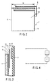
antenna 7, for example, an inverted F-shaped antenna shown in FIG. 2 is used. For this inverted F-shaped antenna 7, for example, arectangular antenna substrate 11 is used, agroove 12 is disposed along an upper side of the substrate to form anelement 13 which is a radio wave radiation element in the upper side of theantenna substrate 11, and another region is formed as a ground (GND) 14. Moreover, in theelement 13, apower supply point 15 is disposed in a position near a base portion. In this case, the position of thepower supply point 15 is set so that an impedance in the point indicates, for example, 50 Ω. - For the
antenna substrate 11, a metal plate having a thickness, for example, of about 0.1 mm is used, and the opposite surfaces of the substrate are laminate-treated and protected. A width W of theantenna substrate 11 is set substantially to a 1/4 wavelength (λ) of the wavelength (λ) of a desired frequency. A concrete size of theantenna substrate 11 is about 30 X 30 mm, for example, when radio waves of a 2.4 GHz band are used. Moreover, thegroove 12 has a width of about 2 mm, and theelement 13 has a width of about 1 mm. - Here, a rectangular
dielectric material 8 formed, for example, by a synthetic resin is disposed so as to be movable in a vertical direction with respect to one plane side of theantenna 7. When an interval between thedielectric material 8 andantenna 7 is set to D, a resonance frequency of theantenna 7 is determined in accordance with the length of D. - FIG. 3 is a sectional side view showing a state in which the inverted F-shaped
antenna 7 is actually mounted on thedisplay portion case 3. - The
antenna 7 is fixed to the upper portion of thedisplay portion case 3 using adhesives. In this case, theantenna 7 is disposed while a side with theelement 13 formed thereon is projected upwards from the upper end of theLCD panel 4 by a predetermined width (e.g., about 5 to 6 mm). This prevents transmission/reception of radio waves by theelement 13 from being influenced by theLCD panel 4. - Moreover, the
dielectric material 8 is disposed on one plane side of theantenna 7 so as to be movable by a movement mechanism described later. Thisdielectric material 8 has a size sufficient to include at least a radio wave radiation portion formed in the upper end of theantenna 7. Thereby, the radio wave radiation portion of theantenna 7 is easily influenced by the permittivity of thedielectric material 8. - Here, for example, when the
dielectric material 8 is closely attached to theantenna 7, the resonance frequency of theantenna 7 moves to a low side by the frequency which depends on the permittivity of thedielectric material 8. On the other hand, when thedielectric material 8 is detached from theantenna 7, and the interval D between theantenna 7 anddielectric material 8 increases, a degree of the influence of the permittivity of thedielectric material 8 onto theantenna 7 drops. Therefore, the resonance frequency of theantenna 7 moves to a high side. - This state will be described with respect to FIGS. 4 and 5A to 5C.
- FIG. 4 is an equivalent circuit showing a frequency characteristic of the
antenna 7. - The
antenna 7 can be represented by a series circuit of a coil L and capacitor C shown in FIG. 4. An inductance of the coil L is determined by the length of theelement 13 of theantenna 7 and the position of thepower supply point 15. - A resonance frequency f0 of the
antenna 7 is represented by:
Moreover, the capacitor C is represented by:
Here, εr denotes a non-permittivity, ε0 denotes the permittivity in vacuum, d denotes a distance between polar plates of the capacitor, and S denotes a polar plate area. - Now, when the
dielectric material 8 is brought close to theantenna 7, εr of the above equation (2) increases. That is, when the interval D between theantenna 7 anddielectric material 8 is shortened, the non-permittivity εr increases. With the increase of εr, the resonance frequency f0 lowers by the above equation (1). - FIGS. 5A to 5C are diagrams showing one example of the resonance frequency of the
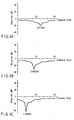
antenna 7. FIG. 5A shows that a distance between theantenna 7 anddielectric material 8 is not less than a predetermined distance (distance in which theantenna 7 is not influenced by the dielectric material 8) (characteristics substantially of a single unit of the antenna 7). FIG. 5B shows that the interval D between theantenna 7 anddielectric material 8 is 1 mm. FIG. 5C shows that the interval D between theantenna 7 anddielectric material 8 is 0 mm (i.e., thedielectric material 8 is closely attached to the antenna 7). In FIGS. 5A to 5C, an abscissa indicates the frequency [GHz], and an ordinate indicates a return loss of the radio wave [dB]. A frequency band in which the return loss becomes minimum is the resonance frequency of theantenna 7 at this time. - As shown in FIG. 5A, the resonance frequency of the
antenna 7 is 2.617 GHz in a case in which the frequency is not influenced by thedielectric material 8. On the other hand, with the influence of thedielectric material 8, the resonance frequency of theantenna 7 fluctuates in accordance with the interval D between theantenna 7 anddielectric material 8. That is, the shorter the interval D is, the lower the resonance frequency becomes. In this example, as shown in FIG. 5B, the frequency is 2.438 GHz with the interval D of 1 mm, and as shown in FIG. 5C, the frequency is 2.239 GHz with the interval D of 0 mm. - In this manner, the resonance frequency of the
antenna 7 is determined in accordance with the interval D between theantenna 7 anddielectric material 8. The position of thedielectric material 8 is adjusted by amovement mechanism 21, for example, as shown in FIGS. 6A and 6B. - FIGS. 6A and 6B are diagrams showing a constitution example of the
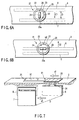
movement mechanism 21 which moves thedielectric material 8 in the vertical direction with respect to a plane of theantenna 7. - As shown in FIG. 6A, the
movement mechanism 21 includes a circular graduatedplate 22, a circularrotary plate 23 which rotates on the graduatedplate 22, and aknob portion 24 disposed on therotary plate 23. The graduatedplate 22 is fixed to the upper end of thedisplay portion case 3 by the adhesives. Therotary plate 23 rotates about ashaft 23a which is a support point. Thisrotary plate 23 is slidably attached to acenter point 25 of thedielectric material 8. Theknob portion 24 is used as an operation point for moving thedielectric material 8. - In this constitution, when a user operates the
knob portion 24 with fingers to rotate therotary plate 23 in an arrow b1 direction, thedielectric material 8 moves toward theantenna 7 in an arrow c1 direction. In this case, thedielectric material 8 is guided by a guide mechanism (not shown) disposed in thedisplay portion case 3 to move keeping a parallel state with theantenna 7. The interval D between theantenna 7 anddielectric material 8 is narrowed by movement of thedielectric material 8 in the arrow c1 direction. Thereby, the resonance frequency band of theantenna 7 is adjusted toward a low side. - A plurality of
graduations 26 are attached along a circumferential direction in an outer periphery of the graduatedplate 22. Thesegraduations 26 are adjusted to the frequency bands of the plurality ofradio modules PC 1. The user can use thesegraduations 26 as measures to easily perform a frequency adjustment operation. Therotary plate 23 includes a structure which is rotatable in stages for each of thesegraduations 26. - FIG. 6B shows that the
rotary plate 23 has been rotated to a third graduation position. In this state, when therotary plate 23 is rotated in an arrow b2 direction, thedielectric material 8 moves in an arrow c2 direction. Thereby, the resonance frequency band of theantenna 7 is adjusted toward a high side. - When the
dielectric material 8 is moved with respect to theantenna 7 in this manner, the resonance frequency band of theantenna 7 can be switched. Therefore, all the frequency bands of therespective radio modules antenna 7. In this case, the resonance frequency band of theantenna 7 is constituted to be appropriately switched by the movement of thedielectric material 8. Therefore, the shape of theantenna 7 is not complicated as compared with a structure in which a plurality of resonance frequency bands have heretofore been imparted to theantenna 7. Moreover, a usable band is not narrowed. - It is to be noted that in the examples of FIGS. 6A and 6B, the movement of the
dielectric material 8 in three stages has been described, but it is also possible to move the material further finely. - Moreover, as shown in FIG. 7, even in a constitution in which the
dielectric material 8 is moved in a horizontal direction with respect to the plane of theantenna 7, the resonance frequency band of theantenna 7 can be adjusted in the same manner as described above. - FIG. 7 shows the constitution example of a
movement mechanism 31 which moves thedielectric material 8 in the horizontal direction with respect to the plane of theantenna 7. - The
movement mechanism 31 includes aslide hole 32, an operation portion 33 fitted into theslide hole 32, and asupport member 34 attached to the operation portion 33. Theslide hole 32 is formed in a longitudinal direction with respect to theantenna 7 in the upper end of thedisplay portion case 3. The operation portion 33 is slidably attached to theslide hole 32. Thesupport member 34 extends from the bottom portion of the operation portion 33, and supports thedielectric material 8 via theslide hole 32. - In this constitution, when the user moves the operation portion 33 in an arrow d1 direction, the
dielectric material 8 moves in an arrow el direction via thesupport member 34. Thereby, the interval D between theantenna 7 anddielectric material 8 is narrowed, and the resonance frequency band of theantenna 7 is adjusted toward the low side. Moreover, when the operation portion 33 is moved in a direction opposite to an arrow d1, thedielectric material 8 is detached from theantenna 7, and the resonance frequency band of theantenna 7 is adjusted toward the high side. - A plurality of
graduations 35 are attached along theslide hole 32 in the vicinity of theslide hole 32. Thesegraduations 35 are adjusted to the frequency bands of the plurality ofradio modules PC 1. The user can use thesegraduations 35 as the measures to easily perform the frequency adjustment operation. The operation portion 33 includes a structure which is slidable in stages for each of thesegraduations 35. - It is to be noted that in the example of FIG. 7, the movement of the
dielectric material 8 in three stages has been described, but it is also possible to move the material further finely. - Even in the constitution in which the
dielectric material 8 is moved in the horizontal direction with respect to the plane of theantenna 7 in this manner, the resonance frequency of theantenna 7 can be allowed to fluctuate in accordance with the position of thedielectric material 8. Therefore, all the frequency bands of therespective radio modules PC 1 can be covered. - Next, a second embodiment of the present invention will be described.
- The second embodiment is characterized in that the position of the
dielectric material 8 is automatically adjusted. - FIG. 8 is a diagram showing the constitution of the
PC 1 in the second embodiment of the present invention. Thedielectric material 8 is disposed to be movable with respect to theantenna 7 in the same manner as in the first embodiment. It is to be noted that here themovement mechanism 21 shown in FIGS. 6A and 6B is assumed and described as the movement mechanism of thedielectric material 8. - As shown in FIG. 8, the
rotary plate 23 has a radius r, and rotates on theshaft 23a which is the support point. Therotary plate 23 is slidably attached to thecenter point 25 of thedielectric material 8. When therotary plate 23 rotates in the arrow b1 direction, thedielectric material 8 is guided by the guide mechanism (not shown) to move in parallel with theantenna 7 in the arrow c1 direction. Moreover, when therotary plate 23 rotates in a direction opposite to the arrow b1, thedielectric material 8 moves in a direction opposite to the arrow c1. - Here, in the second embodiment, the
PC 1 includes a drivingapparatus 41,input unit 42,control apparatus 43, and table 44. - The driving
apparatus 41 rotates/drives therotary plate 23 based on a control signal outputted from thecontrol apparatus 43. Theinput unit 42 is disposed to input a selection signal of the radio module, and concretely includes thekeyboard 5 shown in FIG. 1. Thecontrol apparatus 43 includes a microprocessor. On receiving the selection signal of the radio module from theinput unit 42, the apparatus refers to the table 44 to control the position of thedielectric material 8. In the table 44, a control signal S for each of the plurality of radio modules mounted on the PC 1 (including radio modules A, B, C here), the length of the interval D between theantenna 7 anddielectric material 8, and information indicating a rotation angle of therotary plate 23 are set. - Next, an operation of the second embodiment will be described.
- FIG. 9 is a flowchart showing a position control of the
dielectric material 8 in the second embodiment. It is to be noted that thecontrol apparatus 43 reads aprogram 43a to execute a process shown in the flowchart. - It is now assumed that three types of radio modules A, B, C different in frequency band from one another are mounted on the
PC 1. The user can select any one from these radio modules A, B, C, for example, on a menu screen (not shown) to perform radio communication. - When the radio module for use in the radio communication is selected (YES in step S11), the selection signal (signal indicating the radio module selected by the user) is given to the
control apparatus 43 through theinput unit 42. Thereby, thecontrol apparatus 43 first identifies the radio module brought in a use state based on the selection signal (step S12). It is to be noted that the use state of each radio module can also be judged from a starting state of an operating system (OS) or driver. - Here, when the radio module A is brought into the use state (YES in step S13), the
control apparatus 43 refers to the table 44 to judge the position of thedielectric material 8 for the radio module A (step S14). In an example of the table 44 shown in FIG. 8, the position of thedielectric material 8 is D1 with respect to the radio module A, and a control signal for that is "01". Therefore, when thecontrol apparatus 43 outputs the control signal "01" to the drivingapparatus 41, therotary plate 23 is rotated only by a predetermined angle (step S15), and the interval between theantenna 7 anddielectric material 8 is adjusted to D1 (step S16). - This also applies, when the radio module B or C is brought into the use state.
- That is, with the radio module B (YES in step S17), the
control apparatus 43 refers to the table 44 to output a control signal "10" to the drivingapparatus 41, and thereby the interval between theantenna 7 anddielectric material 8 is adjusted to D2 (steps S18 to S20). Moreover, with the radio module C (YES in step S21), thecontrol apparatus 43 refers to the table 44 to output a control signal "11" to the drivingapparatus 41, and thereby the interval between theantenna 7 anddielectric material 8 is adjusted to D3 (steps S21 to S24). - The interval D between the
antenna 7 anddielectric material 8 is automatically adjusted in accordance with the use state of each radio module in this manner. Therefore, unless the user performs the frequency adjustment operation as in the first embodiment, the resonance frequency of theantenna 7 can be switched for each of the respective radio modules. - It is to be noted that an example of a rotation mechanism has been described herein, but the present invention is not limited to this example, and it is also possible to apply a sliding mechanism which is slidable in the vertical direction with respect to the antenna plane.
- Moreover, here the case in which the
dielectric material 8 is moved in the vertical direction with respect to theantenna 7 has been assumed and described. However, the present invention can also be applied even in a case in which themovement mechanism 31 shown in FIG. 7 moves thedielectric material 8 in the horizontal direction with respect to theantenna 7. - Furthermore, in the first and second embodiments, the
dielectric material 8 is disposed only on one plane side of theantenna 7. However, as shown in FIG. 10, a constitution may also be used in whichdielectric materials antenna 7 and thedielectric materials movement mechanism antenna 7. In this constitution, the resonance frequency band of theantenna 7 is determined by an interval Da between theantenna 7 anddielectric material 8a and an interval Db between theantenna 7 anddielectric material 8b. - In this case, for example, if the intervals Da, Db of the
dielectric materials - Moreover, even when the intervals Da, Db can be adjusted in a linked manner, a relative permittivity increases with the use of two dielectric materials. Therefore, it is possible to enlarge an adjustment width of the resonance frequency, and the switching of further more resonance frequencies can be realized.
- Furthermore, with application of automatic adjustment described in the second embodiment, information indicating the control signal for each of the respective radio modules and the intervals Da, Db between the
antenna 7 anddielectric materials antenna 7 in accordance with the use state of each radio module. - A process procedure at this time is similar to that of FIG. 9. That is, first, the
control apparatus 43 identifies the radio module for use in the communication in the respective radio modules. Next, thecontrol apparatus 43 obtains the position information of thedielectric materials control apparatus 43 drives/controls each movement mechanism to move the respectivedielectric materials dielectric materials antenna 7 is automatically adjusted. - Moreover, the inverted F-shaped antenna has been described as the example of the
antenna 7, but the present invention is not limited to this. For example, other antennas such as a dipole antenna, helical antenna, and slot antenna may also be used. - Furthermore, the electronic apparatus of the present invention is not limited to the personal computer, and can be applied to all electronic apparatuses such as a cellular phone as long as the electronic apparatuses require the antenna for the radio communication.
- According to the present invention described above, an electronic apparatus can be obtained which can appropriately switch a resonance frequency of an antenna for each radio module without improving a shape of the antenna.
Claims (16)
- An electronic apparatus comprising:a plurality of radio modules different in frequency band from one another;an antenna for use in common to the respective radio modules;a dielectric material disposed in the vicinity of the antenna;a movement mechanism to support the dielectric material so that the dielectric material can move with respect to the antenna; andswitch means for adjusting an interval between the antenna and dielectric material by the movement mechanism to switch the resonance frequency of the antenna for each of the radio modules.
- The electronic apparatus according to claim 1, wherein the antenna comprises an antenna of a flat plate type, and the dielectric material is disposed on one plane side of the antenna.
- The electronic apparatus according to claim 1, wherein the respective radio modules include a radio module which is for use in a radio LAN and which has a specific frequency band.
- The electronic apparatus according to claim 1, wherein the movement mechanism supports the dielectric material so that the dielectric material can move in a vertical direction with respect to the antenna.
- The electronic apparatus according to claim 2, wherein the movement mechanism supports the dielectric material so that the dielectric material can move in a vertical direction with respect to one plane of the antenna.
- The electronic apparatus according to claim 5, further comprising:an operation portion which can adjust the position of the dielectric material supported by the movement mechanism by a manual operation.
- The electronic apparatus according to claim 1, wherein the movement mechanism supports the dielectric material so that the dielectric material can move in a horizontal direction with respect to the antenna.
- The electronic apparatus according to claim 2, wherein the movement mechanism supports the dielectric material so that the dielectric material can move in a horizontal direction with respect to one plane of the antenna.
- The electronic apparatus according to claim 8, further comprising:an operation portion which can adjust the position of the dielectric material supported by the movement mechanism by a manual operation.
- The electronic apparatus according to claim 2, further comprising:a second dielectric material disposed on the other plane side of the antenna separately from the dielectric material disposed on one plane side of the antenna,wherein the movement mechanism supports the two dielectric materials so that the dielectric materials can move with respect to the antenna.
- The electronic apparatus according to claim 1, further comprising:control means for moving the dielectric material supported by the movement mechanism to a predetermined position in accordance with the use state of each radio module.
- The electronic apparatus according to claim 11, wherein the control means comprises:identification means for identifying the radio module for use in communication in the respective radio modules; anddriving control means for driving the movement mechanism based on the type of the radio module identified by the identification means to move the dielectric material to the predetermined position.
- The electronic apparatus according to claim 12, further comprising:table means in which information concerning an interval between the antenna and dielectric material is set for each of the respective radio modules,wherein the driving control means refers to the table means to move the dielectric material to a position corresponding to the radio module.
- The electronic apparatus according to claim 10, further comprising:control means for moving the two dielectric materials supported by the movement mechanism to predetermined positions in accordance with use states of the respective radio modules.
- The electronic apparatus according to claim 14, wherein the control means comprises:identification means for identifying the radio module for use in communication in the respective radio modules; anddriving control means for driving the movement mechanism based on the type of the radio module identified by the identification means to move the two dielectric materials to the predetermined positions.
- The electronic apparatus according to claim 15, further comprising:table means in which information concerning intervals between the antenna and two dielectric materials is set for each of the respective radio modules,wherein the driving control means refers to the table means to move the two dielectric materials to positions corresponding to the radio module.
Applications Claiming Priority (1)
| Application Number | Priority Date | Filing Date | Title |
|---|---|---|---|
| PCT/JP2003/001537 WO2004073108A1 (en) | 2003-02-14 | 2003-02-14 | Electronic device |
Publications (2)
| Publication Number | Publication Date |
|---|---|
| EP1638163A4 EP1638163A4 (en) | 2006-03-22 |
| EP1638163A1 true EP1638163A1 (en) | 2006-03-22 |
Family
ID=32866118
Family Applications (1)
| Application Number | Title | Priority Date | Filing Date |
|---|---|---|---|
| EP03705149A Withdrawn EP1638163A1 (en) | 2003-02-14 | 2003-02-14 | Electronic device |
Country Status (5)
| Country | Link |
|---|---|
| US (2) | US20040162033A1 (en) |
| EP (1) | EP1638163A1 (en) |
| JP (1) | JPWO2004073108A1 (en) |
| CN (1) | CN1610989A (en) |
| WO (1) | WO2004073108A1 (en) |
Families Citing this family (15)
| Publication number | Priority date | Publication date | Assignee | Title |
|---|---|---|---|---|
| WO2004073108A1 (en) * | 2003-02-14 | 2004-08-26 | Kabushiki Kaisha Toshiba | Electronic device |
| WO2004097976A2 (en) * | 2003-04-28 | 2004-11-11 | Itt Manufacturing Enterprises, Inc | Tuneable antenna |
| JP4829085B2 (en) * | 2006-11-30 | 2011-11-30 | 株式会社東芝 | Electronics |
| JP4235149B2 (en) * | 2004-07-02 | 2009-03-11 | インターナショナル・ビジネス・マシーンズ・コーポレーション | Notebook computer |
| US7639191B2 (en) * | 2005-07-04 | 2009-12-29 | Telefonaktiebolaget L M Ericsson (Publ) | Multi beam repeater antenna for increased coverage |
| US20070076362A1 (en) * | 2005-09-30 | 2007-04-05 | Isaac Lagnado | Computer device having multi-function handle |
| TWI322528B (en) * | 2005-10-17 | 2010-03-21 | Hon Hai Prec Ind Co Ltd | Antenna frequency modulating device |
| CN1960057B (en) * | 2005-10-31 | 2011-06-15 | 富士康(昆山)电脑接插件有限公司 | Device for adjusting frequency of antenna |
| US7242355B2 (en) * | 2005-11-23 | 2007-07-10 | Sony Ericsson Mobile Communications Ab | Frequency band switching of an antenna arrangement |
| JP4977438B2 (en) * | 2006-10-25 | 2012-07-18 | 日本電気株式会社 | Communication device and portable communication terminal using the same |
| JP5662801B2 (en) * | 2007-11-16 | 2015-02-04 | ホリンワース ファンド,エル.エル.シー. | Filter design method and metamaterial structure based filter |
| WO2009137302A2 (en) * | 2008-05-06 | 2009-11-12 | Rayspan Corporation | Single cable antenna module for laptop computer and mobile devices |
| US8442467B1 (en) * | 2009-02-18 | 2013-05-14 | Sprint Communications Company L.P. | Wireless communication device with a multi-band antenna |
| JP7413878B2 (en) * | 2019-08-30 | 2024-01-16 | 株式会社オートネットワーク技術研究所 | In-vehicle communication device |
| US12625528B2 (en) * | 2024-04-24 | 2026-05-12 | Dell Products L.P. | Couple fed corner frame antenna in an information handling system |
Family Cites Families (16)
| Publication number | Priority date | Publication date | Assignee | Title |
|---|---|---|---|---|
| JPH0265504A (en) * | 1988-08-31 | 1990-03-06 | Yamatake Honeywell Co Ltd | Microstrip antenna |
| JP3308558B2 (en) * | 1991-05-02 | 2002-07-29 | 富士通株式会社 | Antenna module |
| JP2573436B2 (en) * | 1991-06-25 | 1997-01-22 | 松下電工株式会社 | Antenna device |
| JPH0969717A (en) * | 1995-09-01 | 1997-03-11 | Murata Mfg Co Ltd | Chip antenna |
| JP3030360B2 (en) * | 1995-12-01 | 2000-04-10 | 日本電気株式会社 | Flat antenna for portable radio |
| JPH09162632A (en) * | 1995-12-04 | 1997-06-20 | Fujitsu Ltd | Microstrip antenna |
| JPH11136023A (en) * | 1997-10-27 | 1999-05-21 | Nec Corp | Micro strip antenna |
| JP2000134031A (en) * | 1998-10-28 | 2000-05-12 | Murata Mfg Co Ltd | Antenna system, antenna using same and transmitter- receiver |
| DE19959983C2 (en) * | 1999-12-13 | 2002-05-02 | Siemens Ag | Radio transmitter / radio receiver with tunable antenna |
| JP2001345626A (en) * | 2000-06-02 | 2001-12-14 | Mitsumi Electric Co Ltd | Helical antenna and resonance frequency adjusting method thereof |
| JP3980859B2 (en) | 2000-10-13 | 2007-09-26 | 松下電器産業株式会社 | antenna |
| JP2002232319A (en) * | 2001-02-01 | 2002-08-16 | Fujitsu Ltd | Information processing apparatus and communication monitoring control program |
| US6437747B1 (en) * | 2001-04-09 | 2002-08-20 | Centurion Wireless Technologies, Inc. | Tunable PIFA antenna |
| JP3989200B2 (en) * | 2001-07-26 | 2007-10-10 | 株式会社東芝 | Computer |
| AU2002350102A1 (en) * | 2001-11-02 | 2003-05-19 | Skycross, Inc. | Dual band spiral-shaped antenna |
| WO2004073108A1 (en) * | 2003-02-14 | 2004-08-26 | Kabushiki Kaisha Toshiba | Electronic device |
-
2003
- 2003-02-14 WO PCT/JP2003/001537 patent/WO2004073108A1/en not_active Ceased
- 2003-02-14 CN CNA038011026A patent/CN1610989A/en active Pending
- 2003-02-14 EP EP03705149A patent/EP1638163A1/en not_active Withdrawn
- 2003-02-14 JP JP2004568188A patent/JPWO2004073108A1/en active Pending
- 2003-06-27 US US10/608,522 patent/US20040162033A1/en not_active Abandoned
-
2004
- 2004-02-10 US US10/776,801 patent/US6967623B2/en not_active Expired - Fee Related
Also Published As
| Publication number | Publication date |
|---|---|
| EP1638163A4 (en) | 2006-03-22 |
| US20040160371A1 (en) | 2004-08-19 |
| US6967623B2 (en) | 2005-11-22 |
| WO2004073108A1 (en) | 2004-08-26 |
| US20040162033A1 (en) | 2004-08-19 |
| JPWO2004073108A1 (en) | 2006-06-01 |
| CN1610989A (en) | 2005-04-27 |
Similar Documents
| Publication | Publication Date | Title |
|---|---|---|
| EP2780981B1 (en) | Methods and apparatus for controlling tunable antenna systems | |
| US6967623B2 (en) | Electronic apparatus having an antenna with variable dielectric to optimize radio communications at different frequencies | |
| US7369828B2 (en) | Electronically tunable quad-band antennas for handset applications | |
| TWI312209B (en) | Tunable dual-antenna system for multiple frequency band operation | |
| US7205942B2 (en) | Multi-band antenna arrangement | |
| EP1738434B1 (en) | Multi-band compact pifa antenna with meandered slot(s) | |
| US9270012B2 (en) | Electronic device with calibrated tunable antenna | |
| US9406998B2 (en) | Distributed multiband antenna and methods | |
| CN101809813B (en) | Adjustable multi-band antenna | |
| EP2122837B1 (en) | Multi-band tunable frequency reconfigurable antennas using higher order resonances | |
| US20070268190A1 (en) | Multi-band antenna for GSM, UMTS, and WiFi applications | |
| EP2466681B1 (en) | Handheld device and planar antenna thereof | |
| CN111786134B (en) | Mobile device and antenna structure | |
| EP3793024B1 (en) | Electronic device comprising an antenna structure and a sensing pad of a proximity sensor | |
| KR20050062608A (en) | Narrow width dual/tri ism band pifa for wireless applications | |
| EP2075874B1 (en) | Planar monopole antenna and electronic device | |
| WO2002013307A1 (en) | Antenna | |
| EP3189559A1 (en) | Reconfigurable casing antenna system | |
| CN111697317B (en) | Mobile device | |
| EP3010081A1 (en) | Mobile device | |
| CN106340709B (en) | Deformable mobile device | |
| WO2009054600A1 (en) | Antenna system using housings of electronic device and electronic device comprising the same | |
| US20250240048A1 (en) | Wireless device | |
| CN103633450A (en) | Antenna and electronic equipment | |
| CN119447815B (en) | Antenna assembly and electronic equipment |
Legal Events
| Date | Code | Title | Description |
|---|---|---|---|
| PUAI | Public reference made under article 153(3) epc to a published international application that has entered the european phase |
Free format text: ORIGINAL CODE: 0009012 |
|
| 17P | Request for examination filed |
Effective date: 20040302 |
|
| A4 | Supplementary search report drawn up and despatched |
Effective date: 20051216 |
|
| DAX | Request for extension of the european patent (deleted) | ||
| RBV | Designated contracting states (corrected) |
Designated state(s): DE FR GB |
|
| STAA | Information on the status of an ep patent application or granted ep patent |
Free format text: STATUS: THE APPLICATION IS DEEMED TO BE WITHDRAWN |
|
| 18D | Application deemed to be withdrawn |
Effective date: 20060831 |