EP1637877A1 - Utraschall-Sensoranordnung für eine Bahnführungsvorrichtung - Google Patents
Utraschall-Sensoranordnung für eine Bahnführungsvorrichtung Download PDFInfo
- Publication number
- EP1637877A1 EP1637877A1 EP05016230A EP05016230A EP1637877A1 EP 1637877 A1 EP1637877 A1 EP 1637877A1 EP 05016230 A EP05016230 A EP 05016230A EP 05016230 A EP05016230 A EP 05016230A EP 1637877 A1 EP1637877 A1 EP 1637877A1
- Authority
- EP
- European Patent Office
- Prior art keywords
- receiver
- block
- transmitter
- transceiver
- sensor system
- Prior art date
- Legal status (The legal status is an assumption and is not a legal conclusion. Google has not performed a legal analysis and makes no representation as to the accuracy of the status listed.)
- Granted
Links
- 239000000463 material Substances 0.000 claims abstract description 188
- 230000005540 biological transmission Effects 0.000 claims description 48
- 230000015572 biosynthetic process Effects 0.000 claims description 24
- 230000007704 transition Effects 0.000 claims description 21
- 230000007613 environmental effect Effects 0.000 claims description 9
- 230000000694 effects Effects 0.000 claims description 4
- 230000002708 enhancing effect Effects 0.000 claims 2
- 230000004044 response Effects 0.000 abstract description 25
- 239000011159 matrix material Substances 0.000 description 22
- 238000010304 firing Methods 0.000 description 16
- 238000010586 diagram Methods 0.000 description 15
- 238000004891 communication Methods 0.000 description 8
- 238000000034 method Methods 0.000 description 8
- 239000012774 insulation material Substances 0.000 description 6
- 230000002457 bidirectional effect Effects 0.000 description 5
- 230000000737 periodic effect Effects 0.000 description 5
- 230000008901 benefit Effects 0.000 description 4
- 230000001143 conditioned effect Effects 0.000 description 4
- 230000001360 synchronised effect Effects 0.000 description 4
- 239000004020 conductor Substances 0.000 description 3
- 239000006261 foam material Substances 0.000 description 3
- 238000004519 manufacturing process Methods 0.000 description 3
- 238000004364 calculation method Methods 0.000 description 2
- 238000003708 edge detection Methods 0.000 description 2
- 239000011810 insulating material Substances 0.000 description 2
- 238000012545 processing Methods 0.000 description 2
- 230000003252 repetitive effect Effects 0.000 description 2
- 239000004809 Teflon Substances 0.000 description 1
- 229920006362 Teflon® Polymers 0.000 description 1
- 229910052782 aluminium Inorganic materials 0.000 description 1
- XAGFODPZIPBFFR-UHFFFAOYSA-N aluminium Chemical compound [Al] XAGFODPZIPBFFR-UHFFFAOYSA-N 0.000 description 1
- 230000008859 change Effects 0.000 description 1
- 238000009795 derivation Methods 0.000 description 1
- 238000003475 lamination Methods 0.000 description 1
- 238000005259 measurement Methods 0.000 description 1
- 229910052751 metal Inorganic materials 0.000 description 1
- 239000002184 metal Substances 0.000 description 1
- 238000012544 monitoring process Methods 0.000 description 1
- 230000002093 peripheral effect Effects 0.000 description 1
- 238000004886 process control Methods 0.000 description 1
- 230000009467 reduction Effects 0.000 description 1
- 229910052710 silicon Inorganic materials 0.000 description 1
- 239000010703 silicon Substances 0.000 description 1
Images


Classifications
-
- G—PHYSICS
- G01—MEASURING; TESTING
- G01D—MEASURING NOT SPECIALLY ADAPTED FOR A SPECIFIC VARIABLE; ARRANGEMENTS FOR MEASURING TWO OR MORE VARIABLES NOT COVERED IN A SINGLE OTHER SUBCLASS; TARIFF METERING APPARATUS; MEASURING OR TESTING NOT OTHERWISE PROVIDED FOR
- G01D5/00—Mechanical means for transferring the output of a sensing member; Means for converting the output of a sensing member to another variable where the form or nature of the sensing member does not constrain the means for converting; Transducers not specially adapted for a specific variable
- G01D5/48—Mechanical means for transferring the output of a sensing member; Means for converting the output of a sensing member to another variable where the form or nature of the sensing member does not constrain the means for converting; Transducers not specially adapted for a specific variable using wave or particle radiation means
-
- B—PERFORMING OPERATIONS; TRANSPORTING
- B65—CONVEYING; PACKING; STORING; HANDLING THIN OR FILAMENTARY MATERIAL
- B65H—HANDLING THIN OR FILAMENTARY MATERIAL, e.g. SHEETS, WEBS, CABLES
- B65H23/00—Registering, tensioning, smoothing or guiding webs
- B65H23/02—Registering, tensioning, smoothing or guiding webs transversely
- B65H23/0204—Sensing transverse register of web
-
- G—PHYSICS
- G01—MEASURING; TESTING
- G01B—MEASURING LENGTH, THICKNESS OR SIMILAR LINEAR DIMENSIONS; MEASURING ANGLES; MEASURING AREAS; MEASURING IRREGULARITIES OF SURFACES OR CONTOURS
- G01B17/00—Measuring arrangements characterised by the use of infrasonic, sonic or ultrasonic vibrations
- G01B17/06—Measuring arrangements characterised by the use of infrasonic, sonic or ultrasonic vibrations for measuring contours or curvatures
-
- G—PHYSICS
- G01—MEASURING; TESTING
- G01N—INVESTIGATING OR ANALYSING MATERIALS BY DETERMINING THEIR CHEMICAL OR PHYSICAL PROPERTIES
- G01N29/00—Investigating or analysing materials by the use of ultrasonic, sonic or infrasonic waves; Visualisation of the interior of objects by transmitting ultrasonic or sonic waves through the object
- G01N29/22—Details, e.g. general constructional or apparatus details
- G01N29/26—Arrangements for orientation or scanning by relative movement of the head and the sensor
- G01N29/27—Arrangements for orientation or scanning by relative movement of the head and the sensor by moving the material relative to a stationary sensor
-
- G—PHYSICS
- G01—MEASURING; TESTING
- G01S—RADIO DIRECTION-FINDING; RADIO NAVIGATION; DETERMINING DISTANCE OR VELOCITY BY USE OF RADIO WAVES; LOCATING OR PRESENCE-DETECTING BY USE OF THE REFLECTION OR RERADIATION OF RADIO WAVES; ANALOGOUS ARRANGEMENTS USING OTHER WAVES
- G01S15/00—Systems using the reflection or reradiation of acoustic waves, e.g. sonar systems
- G01S15/02—Systems using the reflection or reradiation of acoustic waves, e.g. sonar systems using reflection of acoustic waves
- G01S15/04—Systems determining presence of a target
-
- B—PERFORMING OPERATIONS; TRANSPORTING
- B65—CONVEYING; PACKING; STORING; HANDLING THIN OR FILAMENTARY MATERIAL
- B65H—HANDLING THIN OR FILAMENTARY MATERIAL, e.g. SHEETS, WEBS, CABLES
- B65H2553/00—Sensing or detecting means
- B65H2553/30—Sensing or detecting means using acoustic or ultrasonic elements
-
- G—PHYSICS
- G01—MEASURING; TESTING
- G01N—INVESTIGATING OR ANALYSING MATERIALS BY DETERMINING THEIR CHEMICAL OR PHYSICAL PROPERTIES
- G01N2291/00—Indexing codes associated with group G01N29/00
- G01N2291/04—Wave modes and trajectories
- G01N2291/045—External reflections, e.g. on reflectors
-
- G—PHYSICS
- G01—MEASURING; TESTING
- G01N—INVESTIGATING OR ANALYSING MATERIALS BY DETERMINING THEIR CHEMICAL OR PHYSICAL PROPERTIES
- G01N2291/00—Indexing codes associated with group G01N29/00
- G01N2291/04—Wave modes and trajectories
- G01N2291/048—Transmission, i.e. analysed material between transmitter and receiver
-
- G—PHYSICS
- G01—MEASURING; TESTING
- G01N—INVESTIGATING OR ANALYSING MATERIALS BY DETERMINING THEIR CHEMICAL OR PHYSICAL PROPERTIES
- G01N2291/00—Indexing codes associated with group G01N29/00
- G01N2291/10—Number of transducers
- G01N2291/105—Number of transducers two or more emitters, two or more receivers
Definitions
- Ultrasonic sensors having a transmitter disposed on one side of a web material and a receiver disposed on the other side of the web material for locating the position of an edge of the web material therebetween, are known in the art. Such ultrasonic sensors are mounted perpendicular to the web material direction of travel and suffer from problems due to the reflection of sound between the transmitter, the web material, and the receiver. Noise is thereby introduced into the signal produced by the receiver, and reduces the accuracy of the prior art ultrasonic sensors.
- the present invention relates to a sensor system for accurately determining the position of at least one edge of at least one web material.
- webbing systems have at least one web material, usually a continuous sheet of either transparent or opaque material, which is moving in a direction of travel generally along a longitudinal axis of the at least one web material.
- the at least one web material may deviate in a direction, which is generally transverse or lateral to the direction of travel.
- the determination of the position of at least one edge of the at least one web material by the sensor system of the present invention can be used to measure and correct for the lateral deviation of the at least one web material so that the at least one web material remains traveling along a predetermined path.
- a determination of the position of at least one edge of each of the web materials by the sensor system of the present invention can be used to maintain alignment of the two or more web materials.
- a sensor system is constructed for through-beam operation.
- the sensor system comprises at least one transmitter block having a plurality of transmitters arranged in a staggered matrix formation, at least one receiver block having a plurality of receivers arranged in a staggered matrix formation, and a master unit for controlling the plurality of transmitters of the at least one transmitter block and the plurality of receivers of the at least one receiver block.
- the plurality of transmitters of the at least one transmitter block are capable of selectively transmitting ultrasonic signals.
- the plurality of receivers of the at least one receiver block are capable of receiving at least a portion of the ultrasonic signals transmitted by the plurality of transmitters, and in response thereto, generating receiver output signals indicative of the ultrasonic signals received.
- the at least one receiver block is disposed opposite the at least one transmitter block and is spaced a distance from the at least one transmitter block so as to define a sensor field of view therebetween.
- the at least one web material travels through at least a portion of the sensor field of view, the at least one web material interferes with at least a portion of the ultrasonic signal transmitted by the plurality of transmitters of the at least one transmitter block.
- the receiver output signals generated by the plurality of receivers of the receiver block in response to the receiving at least a portion of the ultrasonic signals is indicative of the position of at least a portion of the at least one web material as at least a portion of the at least one web material is moved along a path in between the at least one transmitter block and the at least one receiver block of the sensor system.
- the master unit periodically transmits to each of the transmitters of the at least one transmitter block a transmitter drive signal to cause the transmitters to "fire” or transmit periodic ultrasonic signals.
- the master unit outputs receiver cutoff signals to selectively toggle each of the receivers in between a first mode, wherein the receiver is permitted to form the receiver output signal responsive to the receiver sensing ultrasonic signals, and a second mode wherein the receiver is restricted from providing the receiver output signal.
- the master unit controls the firing sequence and/or frequency of the transmitters so that each transmitter (or group of transmitters) transmits ultrasonic signals at a different time and/or frequency than adjacently disposed transmitters (or groups of transmitters).
- the master unit also controls the reception sequence of the receivers so that each receiver (or group of receivers) receives ultrasonic signals at a different time than adjacently disposed receivers (or groups of receivers), generally in accordance with the firing sequence of the transmitters.
- the master unit receives the receiver output signals generated by the plurality of receivers responsive to the receivers receiving at least a portion of the ultrasonic signals transmitted by the plurality of transmitters.
- a threshold value e.g., a "no signal” to "full signal” transition
- the master unit can determine the position of at least one edge of the at least one web material and output a sensor output signal indicative of the same.
- the comparison provides the web edge vicinity, which is used to establish a proportional band.
- the master unit can determine a width of the at least one web material, and/or transitions between two or more web materials, and generate sensor output signals indicative of the same.
- a sensor system is constructed for reflective operation.
- the sensor system comprises at least one transceiver block having a plurality of transceivers arranged in a staggered matrix formation, at least one reflector, and a master unit for controlling the plurality of transceivers of the at least one transceiver block.
- the plurality of transceivers of the at least one transceiver block are capable of selectively transmitting ultrasonic signals, and are also capable of receiving at least a portion of the ultrasonic signals and in response thereto, generate receiver output signals indicative of the ultrasonic signals received.
- the at least one reflector is capable of reflecting at least a portion of the ultrasonic signals transmitted by the plurality of transceivers back to the plurality of transceivers so that at least a portion of the reflected ultrasonic signals can be received by the plurality of transceivers.
- the at least one reflector is disposed opposite the at least one transceiver block and is spaced a distance from the at least one transceiver block so as to define a sensor field of view therebetween. As the at least one web material travels through at least a portion of the sensor field of view, the at least one web material interferes with at least a portion of the ultrasonic signals transmitted by the plurality of transceivers of the at least one transceiver block and reflected by the at least one reflector.
- the receiver output signals generated by the plurality of transceivers is indicative of the position of at least a portion of the at least one web material as at least a portion of the at least one web material is moved along a path in between the at least one transceiver block and the at least one reflector of the sensor system.
- the master unit periodically transmits to each of the transceivers of the transceiver block a transmitter drive signal to cause the transceivers to "fire” or transmit periodic ultrasonic signals.
- the master unit outputs receiver cutoff signals to selectively toggle each of the transceivers in between a first mode wherein the transceiver is permitted to form the receiver output signal responsive to the transceiver sensing ultrasonic signals, and a second mode wherein the transceiver is restricted from providing the receiver output signal.
- the master unit controls the firing sequence and/or frequency of the transceivers so that each transceiver (or group of transceivers) transmits ultrasonic signals at a different time and/or frequency than adjacently disposed transceivers (or groups of transceivers).
- the master unit also controls the reception sequence of the transceivers so that each transceiver (or group of transceivers) receives ultrasonic signals at a different time than adjacently disposed transceivers (or groups of transceivers), generally in accordance with the firing sequence of the transceivers.
- the master unit receives the receiver output signals generated by the plurality of transceivers responsive to the transceivers receiving ultrasonic signals. By comparing the receiver output signals to a threshold value, or by comparing the receiver output signals relative to each other, the master unit can determine the position of at least one edge of the at least one web material, a width of the at least one web material, and/or transitions between two or more web materials, and generate sensor output signals indicative of the same.
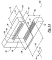
- FIG. 1a is a perspective, diagrammatic view of one embodiment of a sensor system constructed for through-beam operation, in accordance with the present invention (wherein one web material is being sensed).
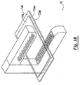
- FIG. 1b is a perspective, diagrammatic view of the sensor system depicted in Fig. 1a, wherein two web materials of different acoustic opacity are being sensed.
- FIG. 1c is a perspective, diagrammatic view of another embodiment of the sensor system constructed for through-beam operation, in accordance with the present invention.
- FIG. 2 is a block diagram of one embodiment of a sensor system constructed for through-beam operation in accordance with the present invention.
- FIG. 3a is an elevational, diagrammatic view of one embodiment of a transmitter block of the sensor system.
- FIG. 3b is a partial, elevational view, in more detail, of one embodiment of an arrangement of a plurality of transmitters of the transmitter block depicted in FIG. 3a.
- FIG. 4a is an elevational, diagrammatic view of one embodiment of a receiver block of the sensor system.
- FIG. 4b is a partial, elevational view, in more detail, of one embodiment of an arrangement of a plurality of receivers of the receiver block depicted in FIG. 4a.
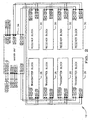
- FIG. 5, is a block diagram of one embodiment of a master unit of the sensor system.
- FIG. 6 is a block diagram of one embodiment of a transmitter block of the sensor system.
- FIG. 7a is a block diagram of one embodiment of a transmit circuit of the transmitter block.
- FIG. 7b is a block diagram of another embodiment of a transmit circuit of the transmitter block.
- FIG. 8, is a block diagram of one embodiment of a receiver block of the sensor system.
- FIG. 9a is a block diagram of one embodiment of a receive circuit of the receiver block.
- FIG. 9b is a block diagram of another embodiment of the receive circuit of the receiver block.
- FIG. 9c is a block diagram of another embodiment of the receive circuit of the receiver block.
- FIG. 10a is a perspective, diagrammatic view of one embodiment of a sensor system constructed for reflective operation in accordance with the present invention (wherein one web material is being sensed).
- FIG. 10b is a perspective, diagrammatic view of the sensor system depicted in Fig. 10a, wherein two web materials of different acoustic opacity are being sensed.
- FIG. 10c is a perspective, diagrammatic view of another embodiment of the sensor system constructed for reflective operation in accordance with the present invention.
- FIG. 11 is a block diagram of one embodiment of a sensor system for reflective operation constructed in accordance with the present invention.
- FIG. 12a is an elevational, diagrammatic view of one embodiment of a transceiver block of the sensor system.
- FIG. 12b is a partial, elevational view, in more detail, of one embodiment of an arrangement of a plurality of transceivers of the transceiver block depicted in FIG. 12a.
- FIG. 13, is a block diagram of one embodiment of a master unit of the sensor system.
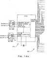
- FIG. 14, is a block diagram of one embodiment of a transceiver block of the sensor system.
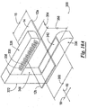
- a sensor system 10 which is constructed in accordance with the present invention.
- the sensor system 10 is adapted and constructed to accurately sense at least one web material 14 so as to determine the position of at least one edge 12 of the at least one web material 14, a width 15 of the at least one web material 14, a transition between two web materials 14, or combinations thereof.
- the at least one web material 14 is a continuous sheet of transparent or opaque material moving in a web direction of travel 16, which is generally along the longitudinal axis of the at least one web material 14. As the at least one web material 14 moves along the web direction of travel 16, the at least one web material 14 may deviate in a direction 18, which is generally transverse or lateral to the web direction of travel 16.
- the sensor system 10 includes a housing 22 which is adapted to receive at least one transmitter block 26 and at least one receiver block 30.
- the at least one transmitter block 26 of the sensor system 10 includes a plurality of transmitters 38 (shown in phantom, only two being labeled in Fig. 1 a for purposes of clarity). Each transmitter 38 is selectively capable of generating ultrasonic signals.
- the at least one receiver block 30 of the sensor system 10 includes a plurality of receivers 42 (only two being labeled in Fig. 1 a for purposes of clarity). Each receiver 42 is selectively capable of receiving ultrasonic signals, and generating a receiver output signal indicative of the ultrasonic signals received.
- the sensor system 10 can include more than one transmitter block 26, and more than one receiver block 30.
- the sensor system 10 is shown in Fig. 2 as having four transmitter blocks 26 and four receiver blocks 30, it should be understood that the sensor system 10 can have any number of transmitter blocks 26 and any number of receiver blocks 30.
- the sensor system 10 includes the same number of receiver blocks 30 as there are transmitter blocks 26 in the sensor system 10 so that each receiver block 30 can be paired with a corresponding transmitter block 26.
- the present invention contemplates that more than one transmitter block 26 can be paired or grouped with one receiver block 30, and more than one receiver block 30 can be paired or grouped with one transmitter block 26.
- each receiver block 30 will have the same number of receivers 42 as there are transmitters 38 in the paired transmitter block 26 so that each receiver 42 in the receiver block 30 can be paired with a corresponding transmitter 38 in the transmitter block 26.
- the housing 22 is preferably mounted perpendicularly with respect to the web direction of travel 16, and the at least one transmitter block 26 and at least one receiver block 30 are on opposite sides of the at least one web material 14 and are disposed such that the ultrasonic signals transmitted by the plurality of transmitters 38 of the at least one transmitter block 26 are substantially projected onto the plurality of receivers 42 of the at least one receiver block 30.
- the housing 22 serves to space the at least one transmitter block 26 from the at least one receiver block 30 to form a sensor field of view 46 therebetween.
- the sensor field of view 46 has a length 50, a width 54, and a sensing gap 58.
- the length 50 of the sensor field of view 46 is greater then the width 15 of the at least one web material 14.
- the length 50 of the sensor field of view 46 can be less than the width 15 of the at least one web material 14, such as for example when only one edge 12 of the at least one web material 14 is being sensed.
- the width 54 of the sensor field of view generally depends on the size, proportional band, and arrangement of the transmitters 38 of the at least one transmitter block 26 and receivers 42 of the at least one receiver block 30 (as discussed in further detail below).
- the sensing gap 58 of the sensor field of view 46 extends generally in between the at least one transmitter block 26 and the at least one receiver block 30, and is sufficient to dispose the at least one web material 14 therebetween.
- the sensor field of view 46 is preferably continuous, it should be understood that the sensor field of view 46 can also be discontinuous.
- the transmitter blocks 26 and/or receiver blocks 30 can be staggered or disposed remotely from each other.
- the at least one web material 14 will interfere with or block the passage of at least a portion of the ultrasonic signals transmitted by the plurality of transmitters 38 because the ultrasonic signals, upon reaching the at least one web material 14, are partially absorbed, reflected, or deflected by the at least one web material 14.
- the ultrasonic signals received by each receiver 42 will depend on the relative location of the at least one web material 14 to the receiver 42.
- the ultrasonic signals received by the receivers 42 of the at least one receiver block 30 are indicative of the position of at least one edge 12 of the at least one web material 14, as well as other information which can be determined therefrom, such as the center position of the at least one web material 14 and transitions between two or more web materials 14. Further, with real-time sensing, deviations of the at least one web material 14 in the direction 18 can be detected as the at least one web material 14 moves through at least a portion of the sensor field of view 46.
- Each of the transmitters 38 of the at least one transmitter block 26 can be any transducer capable of generating ultrasonic signals in response to the receipt of electrical signals.
- each of the transmitters 38 can be an ultrasonic transmitter or an ultrasonic transceiver operating in transmitter mode.
- each transmitter 38 when each of the transmitters 38 are of the same resonant frequency, each transmitter 38 can be a MA200D1 High-Frequency Ultrasonic Sensor, having an operating frequency range from about 220 kHz ⁇ about 20 kHz, available from Murata Manufacturing Co., Ltd. of Japan.
- each of the transmitters 38 can operate in another frequency range.
- a frequency range can be selected so as to eliminate interference from expected environmental sound waves (e.g.
- each transmitter 38 can have a different operating frequency than an adjacently or nearly disposed transmitter 38 in the same transmitter block 26 or in another adjacently disposed transmitter block 26 so as to help reduce interference between ultrasonic signals generated by two or more transmitters 38.
- each transmitter 38 of the at least one transmitter block 26 is a discrete unit that can be independently disposed in and supported by the housing 22, and has its own sound conducting material, which can be made of silicon or teflon, for example.
- each transmitter 38 of the at least one transmitter block 26 can be isolated from the other transmitters 38 and disposed on a different plane.
- the at least one transmitter block 26 may also include sound insulation material 59 (as shown for example in FIG. 3a), such as for example rubber or foam material, disposed substantially around a portion of each of the transmitters 38 so as to insulate the transmitters 38 from undesired signals and vibrations (e.g.
- the transmitters 38 can transmit ultrasonic signals to the receivers 42 of the at least one receiver block 30.
- Such undesired signals can include, for example, external sound waves (such as from other equipment near the sensor system 10), deflected ultrasonic signals (such as from the housing 22), and other noise or vibrations (such as from the housing 22).
- the sound insulation material 59 is disposed around a portion of each of the transmitters 38 such that each transmitter 38 remains independent and thus further insulated from adjacently disposed transmitters 38 in the at least one transmitter block 26.
- the transmitters 38 have a symmetric circular shape, such as shown for example in Fig. 1a.
- the transmitters 38 can have any shape, and can be either symmetric or asymmetric, generally depending on the desired beam profile of the produced ultrasonic signals.
- the transmitters 38 may have an asymmetric rectangular shape.
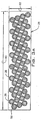
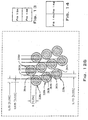
- the plurality of transmitters 38 are arranged in the at least one transmitter block 26 in a staggered matrix formation, as shown best in Fig. 3a.
- the transmitters 38 are disposed in staggered rows, whereby each transmitter 38 in the rows effectively increases a length 60 of the at least one transmitter block 26 and each staggered row effectively increases a width 62 of the at least one transmitter block 26.
- the at least one transmitter block 26 is shown in Fig.
- the at least one transmitter block 26 may have any number of transmitters 38 in each row of the staggered matrix formation, and the at least one transmitter block 26 can have any number of rows of transmitters 38. Further, each row may have the same or a different number of transmitters 38 as an adjacently disposed row of transmitters 38.
- Arranging the transmitters 38 in the staggered matrix formation effectively reduces "gaps" or spaces where there is an absence of ultrasonic signals transmitted by the plurality of transmitters 38 of the at least one transmitter block 26 across at least one of the length 50 or the width 54 of the sensor field of view 46, through which at least a portion of the at least one web material 14 passes and is being sensed.
- gaps in the sensor's field of view can occur from spacing between transmitters or receivers as well as from practical limitations of real-world transmitters and receivers, such as geometric dimensions and shapes available, actual effective transmission or reception areas, and proportional band or near-linear operation parameters.
- Gaps reduce the precision and accuracy in the sensing of a web material with respect to all dimension within a sensor's field of view. These effects on sensing performance also generally increase the closer a web material is to the transmitters and receivers because an edge of the web material is more likely to be located within such a gap where there is an absence of the transmission or reception of the ultrasonic signals.
- the plurality of transmitters 38 of the at least one transmitter block 26 provide a more continuous sensor field of view 46 of the sensor system 10 during real-time sensing of the at least one web material 14.
- This more continuous sensor field of view 46 provides more flexibility in the positioning of the at least one web material 14 within the sensor field of view 46, including along the sensing gap 58.
- the staggered matrix arrangement provides more flexibility in the alignment of the web direction of travel 16 of the at least one web material 14 to the sensor system 10, i.e. the sensor system 10 can be used in a non-perpendicular alignment application.
- the transmitters 38 of the at least one transmitter block 26 are positioned near to adjacently disposed transmitters 38 so to decrease the distance between adjacently disposed transmitters while still allowing for mounting and support by the housing 22 for the transmitters 38, and if desired, the insulating material 59.
- each transmitter 38 is arranged in the staggered matrix formation such that at least one edge of a proportional band area of the transmitter 38 is substantially aligned with at least one edge of a proportional band area of an adjacently disposed transmitter 38 and/or at least one edge of a proportional band area of another transmitter 38 along the length 60 of the transmitter block 26, such that gaps along the overall sensing length 60 of the transmitter block 26 are essentially reduced.
- the edges of the proportional band areas are aligned such that the proportional band areas overlap. Overlapping helps to remove gaps and to compensate for such other factors as manufacturing tolerance allowances of other elements of the sensor system 10, such as for example the housing 22 and transmitters 38. Therefore, in such an embodiment, the positioning of the transmitters 38 will generally depend on the physical shape, dimensions, and proportional band area of each of the transmitters 38. In one embodiment, the proportional band area of each transmitter 38 is defined by the 10% - 90% near-linear performance of the transmitter 38. However, other limits and/or considerations may be used to define the proportional band area of each of the transmitters 38.
- each of the transmitters 38 has a 0.75 inch diameter and an effective proportional band area of 0.25 inches as defined by a start point 63 and an end point 64. Because the disposition of the transmitters 38 is repetitive, for purposes of clarity, the disposition of only four transmitters 38a, 38b, 38c, and 38d will be discussed in further detail.
- An end point 64a of the proportional band area of transmitter 38a is aligned with a start point 63b of the proportional band area of transmitter 38b so as to overlap by 0.025 inches along the length 60 of the transmitter block 26.
- An end point 64b of the proportional band area of transmitter 38b is aligned with a start point 63c of the proportional band area of transmitter 38c so as to overlap by 0.025 inches along the length 60 of the transmitter block 26.
- An end point 64c of the proportional band area of transmitter 38c is aligned with a start point 63d of a proportional band of transmitter 38d so as to overlap by 0.025 inches along the length 60 of the transmitter block 26.
- the alignment and overlap of the plurality of transmitters 38 along the length 60 of the at least one transmitter block 26 essentially reduces gaps along the length of the at least one transmitter block 26.
- the transmitters 38 are discussed herein as being arranged so as to reduce gaps along the length 60 of the at least one transmitter block 26, it should also be understood that the same method of alignment of the transmitters 38 can be applied along the width 62 of the at least one transmitter block 26.
- the present invention contemplates that not all gaps along the length 60 and/or width 62 of the at least one transmitter block 26 have to be reduced when disposing the transmitters 38 in the staggered matrix formation.
- the present invention contemplates that at least some of the start points 63 and end points 64 of the proportional band areas may be aligned such that the proportional band areas are spaced a minimal distance apart rather than being overlapped.
- the number of transmitters 38 in each row and the number of rows of transmitters 38 in the staggered matrix formation of the at least one transmitter block 26 can depend on various considerations, such as the intended application of the sensor system 10, the dimensions of the at least one web material 14 or portions thereof being sensed, the dimensions of each of the transmitters 38, allowance for gaps in the transmitter block 26, the desired dimensions of the sensor field of view 46, the number of transmitter blocks 26 and receiver blocks 26 included in the sensor system 10, costs, etc.
- Each of the receivers 42 of the at least one receiver block 30 can be any transducer capable of generating electrical signals in response to the receipt of ultrasonic signals.
- each receiver 42 can be an ultrasonic receiver or an ultrasonic transceiver operating in receiver mode.
- each of the receivers 42 can be a MA200D1 High-Frequency Ultrasonic Sensor, having an operating frequency range from about 220 kHz ⁇ about 20 kHz, available from Murata Manufacturing Co., Ltd. of Japan.
- each of the receivers 42 can operate in another frequency range (generally at the frequency of a corresponding transmitter 38), and the plurality of receivers do not have to operate at the same frequency.
- each receiver 42 of the at least one receiver block 30 is preferably a discrete unit that can be independently disposed in and supported by the housing 22, and has its own sound conducting material. As such, it should be understood that each receiver 42 of the at least one receiver block 30 can be isolated from the other receivers 42 and disposed on a different plane. Further, the at least one receiver block 30 may also include sound insulation material 65 (such as shown for example in FIG. 4a), such as for example rubber or foam material, disposed substantially around a portion of each of the receivers 42 so as to insulate each receiver 42 from adjacent receivers 42, as well as from undesired signals and vibrations (e.g.
- the sound insulation material 65 is disposed around a portion of each of the receivers 42 such that each receiver 42 remains independent and thus further insulated from adjacently disposed receivers 42 in the at least one receiver block 30.
- the receivers 42 have a symmetric circular shape, such as shown for example in Fig. 1a.
- the receivers 42 can have any shape, and can be either symmetric or asymmetric, depending on the beam profile of the ultrasonic signals being received.
- the receivers 42 may have an asymmetric rectangular shape.
- the plurality of receivers 42 are arranged in the at least one receiver block 30 in a staggered matrix formation in a manner similar to the plurality of transmitters 38 of the at least one transmitter block 26.
- the receivers 42 are disposed in staggered rows, whereby each receiver 42 in the rows effectively increases a length 66 of the at least one receiver block 30, and each staggered row effectively increases a width 67 of the at least one receiver block 30.
- placing the receivers 42 in a staggered arrangement effectively reduces gaps where there is an absence of ultrasonic signals received by the plurality of receivers 42 of the at least one receiver block 30 across at least one of the length 50 or the width 54 of the sensor field of view 46, through which at least a portion of the at least one web material 14 passes and is being sensed.
- the at least one receiver block 30 is shown in Fig. 4a as having seven staggered rows of receivers 42, with each row having eight receivers 42, it should be understood that the receiver block 30 may have any number of receivers 42 in each row of the staggered matrix formation, and the receiver block 30 may have any number of rows of receivers 42. Further, each row may have the same or a different number of receivers 42 as an adjacently disposed row of receivers 42.
- the number of receivers 42 in each row and the number of rows of receivers 42 included in the at least one receiver block 30 generally depends on various considerations, such as the number of transmitters 38 in the transmitter block 26, the number of transmitter blocks 26 and receiver blocks 30 included in the sensor system 10, the intended application of the sensor system 10, the dimensions of the at least one web material 14 or portion thereof being sensed, the dimensions of each of the receivers 42, allowance for gaps in the receiver block 30, the desired sensor field of view 46 dimensions, costs, etc.
- each receiver block 30 includes the same number of receivers 42 as there are transmitters 38 in the corresponding transmitter block 26 so that each of the receivers 42 of the receiver block 30 can be paired with a corresponding transmitter 38 of the corresponding transmitter block 26.
- each receiver 42 of the receiver block 30 is positioned and constructed to receive at least a portion of the ultrasonic signal 36 transmitted by a paired transmitter 38 disposed generally opposite the receiver 42.
- each of receivers 42 in the at least one receiver block 30 mirrors that of the corresponding transmitter 38 in the corresponding transmitter block 26.
- the number of rows and the number of receivers 42 in each row of the receiver block 30 will correspond to the number of rows and number of transmitters 38 in each row of the corresponding transmitter block 26 and the disposition of the receivers 42 will be substantially the same as discussed above for the transmitters 38.
- the receivers 42 shown in FIG. 4b which have a 0.75 inch diameter and a proportional band area of 0.25 inches are overlapped by 0.025 inches along the length 66 of the at least one receiver block.
- the sensor system 10 is generally discussed herein as having one transmitter 38 paired to one receiver 42, it should be understood that the present invention contemplates that more than one transmitter 38 can be paired or grouped with one receiver 42, and more than one receiver 42 can be paired or grouped with one transmitter 38.
- the sensor system 10 also includes a master unit 34, which communicates with the at least one transmitter block 26 and the at least one receiver block 30 to control the plurality of transmitters 38 and the plurality of receivers 42.
- the master unit 34 periodically transmits to each of the transmitters 38 of the at least one transmitter block 26 a transmitter drive signal to selectively cause the transmitters 38 to "fire” or transmit periodic ultrasonic signals.
- the master unit 34 to reduce undesired reception and noise by each of the receivers 42, the master unit 34 also selectively outputs receiver cutoff signals to each of the receivers 42 so as to selectively toggle the receiver 42 in between a first mode wherein the receiver 42 is "on” and permitted to form the receiver output signal responsive to the receiver 42 sensing ultrasonic signals, and a second mode wherein the receiver 42 is “off” and restricted from providing the receiver output signal.
- a first mode wherein the receiver 42 is "on” and permitted to form the receiver output signal responsive to the receiver 42 sensing ultrasonic signals
- a second mode wherein the receiver 42 is "off” and restricted from providing the receiver output signal.
- the receiver cutoff signal is continuously maintained in the second mode so as to turn the receiver 42 "off", and selectively toggled to the first mode to turn the receiver 42 "on” for a predetermined time coincident with the transmitting of the transmitter drive signal or a corresponding transmitter 38 so that the receiver 42 can generate the receiver output signal.
- the master unit 34 automatically toggles the receiver cutoff signal from the first mode to the second mode to turn the receiver 42 "off” to restrict the receiver 42 from generating any noise.
- the master unit 34 can further control the firing sequence and/or frequency of the transmitters 38 so that each transmitter 38 (or group of transmitters 38) transmits ultrasonic signals at a different time and/or frequency than adjacently disposed transmitters 38 (or groups of transmitters 38).
- the master unit 34 can synchronize the transmitter drive signals sent to two or more transmitters 38 of the at least one transmitter block 26.
- the master unit 34 can also control the reception sequence of the receivers 42 so that each receiver 42 (or group of receivers 42) receives ultrasonic signals at a different time than adjacently disposed receivers 42 (or groups of receivers 42), generally in accordance with the firing sequence of a corresponding transmitter 38.
- the master unit 34 can synchronize the receiver cutoff signals sent to two or more receivers 42 of the at least one receiver block 30. Further, the master unit 34 can synchronize the transmitter drive signal sent to at least one transmitter 38 and receiver cutoff signal sent to at least one receiver 42, such as a paired transmitter 38 and receiver 42 (as discussed above). Also, when the sensor system 10 includes more than one transmitter block 26 and/or receiver block 30, the master unit 34 can synchronize the transmitter drive signals outputted to the transmitter blocks 26 and/or the receiver cutoff signals outputted to the receiver blocks 30 so as to reduce interference between the transmitters 38 of two or more transmitter blocks 26 and/or receivers 42 of two or more receiver blocks 30.
- synchronize and derivations thereof, is used herein to refer to a timing relationship.
- Synchronize can mean to cause to happen, exist, or arise at precisely the same time or within a certain time period of each other.
- the master unit 34 may also be adapted to send and receive diagnostic data from each of the transmitters 38 and/or each of the receivers 42.
- the master unit 34 also receives the receiver output signals generated by the plurality of receivers 42.
- the master unit 34 utilizes the receiver output signals outputted by the receivers 42 to generate sensor output signals indicative of the position of at least one edge 12 of the at least one web material 14 by setting a threshold value to which the receiver output signals are compared.
- the threshold value is generally set such that when each receiver output signal from each receiver 42 is compared to the threshold value, the comparison indicates whether at least a portion of the ultrasonic signals generated by a corresponding transmitter 38 was interfered with and thus not received by the corresponding receiver 42.
- the comparison of the receiver output signals of the receivers 42 and the threshold value can be utilized by the master unit 34 to determine the position of at least one edge 12 of the at least one web material 14 within the sensor field of view 46.
- the receiver output signals are compared to the threshold value (e.g., a "no signal” to "full signal” transition) so as to locate the web edge vicinity, which is used to establish a proportional band. Then, by measuring the percentage of signal block within the proportional band, the position of at least one edge 12 of the at least one web material 14 is determined. Also, other information can be determined therefrom, such as the center position of the at least one web material 14 and/or transitions between two or more web materials 14.
- the master unit 34 utilizes the receiver output signals outputted by the receivers 42 to generate sensor output signals indicative of the position of at least one edge 12 of the at least one web material 14 by comparing the receiver output signals relative to each other. By comparing the receiver output signals, the master unit 34 can determine the relative amount of ultrasonic signals that were received by each receiver 42. As such, the relative comparison of the output receiver signals can be utilized by the master unit 34 to determine the position of at least one edge 12 of the at least one web material 14 within the sensor field of view 46 by evaluating transitions between receiver output signal values. Also, other information can be determined therefrom, such as the center position of the at least one web material 14 and transitions between two or more web materials 14.
- the master unit 34 can determine the position of at least one edge 12 of the at least one web material 14, a width 15 of the at least one web material 14, a transition between two or more web materials 14, or combinations thereof, and generate at least one sensor output signal indicative of the same.
- the master unit 34 may generate a sensor output signal indicative of the position of a first edge 12a of the at least one web material 14.
- the master unit 34 may output at least two sensor output signals, wherein at least one sensor output signal is indicative of the first edge 12a of the at least one web material 14, and at least one other sensor output signal is indicative of another edge 12b of the at least one web material 14.
- the master unit 34 can output a sensor output signal indicative of the width 15 of the at least one web material 14 by determining the distance between the two edges 12a and 12b of the at least one web material 14.
- the master unit 34 can use the receiver output signals to determine the position of an edge 12aa of the first web material 14a.
- the master unit 34 can also compare the receiver output signals to detect a relative transition in the receive output signals so as to determine the position of an edge 12ab of the second web material 14b, and thereby determine a transition between the two web materials 14a and 14b.
- the information received from comparing the receiver output signals to a threshold value, or by comparing the receiver output signals relative to each other can further be used in other applications of the sensor system 10, such as for example sensing holes or perforations in the at least one web material 14.
- the at least one sensor output signal can be outputted by the master unit 34 to other devices (not shown), such as a for example a conventional web guiding signal processor or computer, which may be in communication with the sensor system 10.
- computers or other serial or parallel connected peripheral devices receiving the at least one sensor output signal may use the at least one sensor output signal for the purpose of controlling the lateral position of the at least one web material 14.
- adjustments to the at least one web material 14 in the direction 18 with a motor controlled pivotal platform can be made in response to the sensor output signal which is indicative of the position of at least one edge 12 of the at least one web material 14.
- Such adjustments can be made for example to maintain the at least one web material 14 traveling along a predetermined and desired travel path.
- the sensor output signals received by such devices may also be used for other purposes such as for example web width measurement, tension control, or alignment of the at least one web material 14.
- the sensor system 10 can also be connected to a serial bus for a wider range of applications to support features, such as for example web width monitoring and output for other process control besides guiding (such as tension control), web centerline calculations, machine center calculations and calibrations, web centerline shift with respect to calibrated machine center anywhere within the sensor field of view 46, display amount of relative web centerline shift with respect to a machine center, near instantaneous web seeking, programmable web centerline shift speed, and/or user interface for basic web guiding and positioning.
- features such as for example web width monitoring and output for other process control besides guiding (such as tension control), web centerline calculations, machine center calculations and calibrations, web centerline shift with respect to calibrated machine center anywhere within the sensor field of view 46, display amount of relative web centerline shift with respect to a machine center, near instantaneous web seeking, programmable web centerline shift speed, and/or user interface for basic web guiding and positioning.
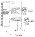
- the master unit 34 includes a controller 67 and a control circuit 68 to output control data to the plurality of transmitters 38 and receivers 42, and to receive data from the plurality of transmitters 38 and receivers 42, such as diagnostic data or sensing data. More specifically, the controller 67 cooperates with the control circuit 68 so that the master unit 34 selectively outputs transmitter drive signals to the plurality of transmitters 38 of the at least one transmitter block 26, selectively outputs receiver cutoff signals to the plurality of receivers 42 of the at least one receiver block 30, and selectively receives receiver output signals outputted by the plurality of receivers 42 of the receiver block 30.
- the controller 67 of the master unit 34 is a microcontroller, such as for example a microcontroller with an ARM9 microprocessor core, available from Atmel Corporation of San Jose, California.
- the control circuit 68 of the master unit 34 is a complex programmable logic device (CPLD) or field-programmable gate array (FPGA), which includes data registers for adder-corrected clock synchronization.
- CPLD complex programmable logic device
- FPGA field-programmable gate array
- the control circuit 68 of the master unit 34 further includes a master clock for synchronization purposes (as discussed further below).
- the master unit 34 may further include a plurality of network interfaces 69, such as for example a bidirectional bus or ethernet connection, so as to be in communication with a network area.
- network interfaces 69 such as for example a bidirectional bus or ethernet connection
- the master unit 34 can synchronize the transmitter drive signals outputted to each transmitter block 26 and/or the receiver cutoff signals outputted to each receiver block 30 via one of the network interfaces 69 so as to minimize interference between the transmitter blocks 26 and/or receiver blocks 30.
- the network interfaces 69 can be used to communicate with other sensor systems 10 and/or other devices.
- the master unit 34 can also include a temperature compensation circuit 70 for sensing and compensating for environmental temperature. Because the transmitters 38, the receivers 42, and various other components of the sensor system 10 may be sensitive to changes in temperature, the master unit 34 can be adapted to correct the receiver output signals for changes in the environmental temperature surrounding the sensor system 10. This temperature compensation provides for a more accurate sensing of the at least one web material 14.
- the temperature compensation circuit 70 includes at least one temperature sensor 71 and an analog-to-digital converter 72.
- the temperature sensor 71 generates a temperature signal indicative of the absolute temperature surrounding the sensor system 10, which is outputted to the master unit 34 via the analog-to-digital converter 72.
- the master unit 34 receives the receiver output signals from the receiver block 30 and the temperature signal from the temperature sensor 71.
- the master unit 34 utilizes at least one of a plurality of stored temperature compensation values to generate sensor output signals which more accurately indicate the position of the of the at least one web material 14.
- a temperature compensation circuit and the operation thereof, is discussed in further detail in U.S. Patent No. 6,289,729, entitled “Ultrasonic Sensor for Web-Guiding Apparatus", the contents of which are expressly incorporated herein by reference.
- the plurality of stored temperature compensation values will be the same for receivers 42 that are of similar size, manufacture, and frequency range. Therefore, if different types of receivers 42 are used or if the receivers 42 operate at different frequency ranges, different temperature compensation values may be stored to generate sensor output values accordingly.
- temperature compensation circuit 70 has been described as being included in the master unit 34, it should be understood that the temperature compensation circuit 70 (or the at least one temperature sensor 71) may be included in the transmitter block 26 or receiver block 30 so as sense the temperature in an area closer to the transmitters 38 or receivers 42, respectively, especially if significant temperature gradients may be expected over the sensor field of view 46.
- the master unit 34 may further include an analog output circuit 73 for outputting the sensor output signals to other devices, such as a for example a conventional web guiding signal processor or computer (not shown), which may be in communication with the sensor system 10 (as discussed above).
- the analog output circuit 73 includes a first E/I converter 74, a second E/I converter 75, a third E/I converter 76, and a digital-to-analog converter 77.
- the master unit 34 outputs a signal which is indicative of the location of the first edge 12a of the web material 14 to the first E/I converter 74 via the digital-to-analog converter 77.
- the master unit 34 outputs a signal which is indicative of the location of the second edge 12b of the web material 14 to the second E/I converter 75 via the digital-to-analog converter 77. Similarly, the master unit 34 outputs a signal which is indicative of the width 15 of the at least one web material 14 to the third E/I converter 76 via the digital-to-analog converter 77.
- the first E/I converter 74 outputs an enhanced sensor output signal indicative of the first edge 12a so that such sensor output signal can be received by the conventional web guiding signal processor.
- the second E/I converter 75 outputs an enhanced sensor output signal indicative of the second edge 12b so that such sensor output signal can be received by the conventional web guiding signal processor.
- the third E/I converter 76 outputs an enhanced signal indicative of the web width 15 so that such signal can be received by the conventional web guiding signal processor. That is, the E/I converters 74, 75, and 76 convert the analog signals received from the digital-to-analog converter 77 and output current signals. These signals can be voltage-to-current converted signals having a range of between 0-20 milliamperes.
- the transmitter block 26 includes the plurality of transmitters 38 (only one being labeled for purposes of clarity), wherein each transmitter 38 is selectively capable of generating ultrasonic signals in response to the transmitter drive signal outputted by the master unit 34 to the transmitter 38.
- each transmitter 38 is selectively capable of generating ultrasonic signals in response to the transmitter drive signal outputted by the master unit 34 to the transmitter 38.
- the transmitter block 26 is shown in Fig. 6 as including sixteen transmitters 38, it should be understood that the transmitter block 26 can have any number of transmitters 38.
- the transmitter block 26 further includes a transmit circuit 78 and a data transmission circuit 79 to exchange data between the master unit 34 and the plurality of transmitters 38.
- the transmit circuit 78 and data transmission circuit 79 cooperate with the master unit 34 to set and synchronize timing patterns for the transmitters 38, to fire the transmitters 38, and to identify or diagnose the transmitters 38 of the at least one transmitter block 26.
- the data transmission circuit 79 which can be for example a complex programmable logic device (CPLD), cooperates with the master unit 34 to control which transmitter 38 (or group of transmitters 38) receives the transmitter drive signal, and the transmit circuit 78 conditions the transmitter drive signal before the transmitter drive signal is used to drive the selected transmitter 38 (or group of transmitters 38).
- CPLD complex programmable logic device
- the master unit 34 selectively outputs transmitter drive signals to the data transmission circuit 79 of the transmitter block 26 via a serial bus, such as for example a bidirectional RS-485.
- the transmitter drive signal is representative of substantially one cycle of a substantially sinusoidally shaped waveform.
- the transmitter drive signal has a preselected frequency of about 220 kHz, and the period at which the master unit 34 transmits the transmitter drive signal is about 5 milliseconds.
- the transmitter drive signals are received by the data transmission circuit 79 which selectively passes the transmitter drive signals to the transmit circuit 78 to fire selected transmitters 38.
- the data transmission circuit 79 communicates with the transmit circuit 78 via a plurality of signal paths so that the transmitter drive signals can be outputted via the transmit circuit 78 to at least one selected transmitter 38 or group of transmitters 38.
- the transmit circuit 78 of the transmitter block 26 includes a combination of one bandpass filter 80 (only one being labeled for purposes of clarity) and one driver 84 (only one being labeled for purposes of clarity) for each of the transmitters 38 of the transmitter block 26, so that each transmitter 38 can be controlled independently of the other transmitters 38.
- the bandpass filters 80 are identical and the drivers 84 are identical if the transmitters 38 operate at the same frequency. However, if the transmitters 38 operate at different frequencies, the bandpass filters 80 will be different.
- the transmitters 38 can also share common components in the transmit circuit 78 to reduce costs and real estate requirements. However, by sharing common components, some flexibility in the setting timing patterns for each transmitter 38 is lost. For example, more than one of the transmitters 38 can share a common bandpass filter 80 and/or driver 84 when operated at the same frequency and/or activated at the same time, such as shown for example in Figs. 7a-7b. Although the transmitters 38 which share common components are shown in Figs. 7a-7b as being adjacently disposed, it should be understood that transmitters 38 that share components in the transmit circuit 78 do not have to be adjacently disposed.
- the sensor system 10 will be discussed below in further detail with respect to Fig. 6 as having a transmit circuit 78 which includes one bandpass filter 80 and one driver 84 for each transmitter 38 of the transmitter block 26.
- a transmit circuit 78 which includes one bandpass filter 80 and one driver 84 for each transmitter 38 of the transmitter block 26.
- each transmitter 38, and corresponding bandpass filter 80 and driver 84 operates in a similar manner, for purposes of clarity, only the operation of one transmitter 38 and corresponding bandpass filter 80 and driver 84 is discussed in further detail below.
- the bandpass filter 80 is tuned to pass substantially only the selected frequency of the transmitter drive signal and to block substantially all other frequencies, including harmonic frequencies and noise which may result from the transmission of the transmitter drive signal or the noise from a 60-Hz supply voltage, for example.
- bandpass filters such as the bandpass filter 80
- substantially only the selected frequency as used herein is intended to encompass the selected frequency and any frequencies within the range of from about 200 kHz to about 240 kHz (when the selected frequency is about 220 kHz), or preferably within about 6.67 percent (+ 6.67%) of the selected frequency, although a greater range may be suitable in some applications.
- the range of frequencies encompassed by such term may also depend on many factors, such as the type of bandpass filter, and the particular selected frequency.
- the bandpass filter 80 receives the transmitter drive signal from the master unit 34 via the data transmission circuit 79, and in response thereto, the bandpass filter 80 conditions the transmitter drive signal to drive the transmitter 38.
- the conditioned transmitter drive signal will be a substantially sinusoidal waveform.
- the bandpass filter 80 outputs the conditioned transmitter drive signal to the driver 84.
- the driver 84 drives the transmitter 38 so as to cause the transmitter 38 to generate ultrasonic signals for the duration of the transmitter drive signal.
- the at least one driver 84 may be push-pull or single ended with the other terminal of the transmitter 38 connected to ground.
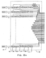
- FIGs. 8A and 8B shown therein in block diagram form is one embodiment of one receiver block 30 constructed in accordance with the present invention.
- the receiver block 30 includes the plurality of receivers 42 (only one being labeled for purposes of clarity), wherein each receiver 42 is selectively capable of receiving ultrasonic signals in response to the receiver cutoff signal outputted by the master unit 34 to the receiver 42.
- the receiver block 26 is shown in Figs. 8A and 8B as including sixteen receivers 42, it should be understood that the receiver block 30 can have any number of receivers 42.
- the receiver block 30 further includes a receive circuit 88 and a data transmission circuit 90 to exchange data between the master unit 34 and the plurality of receivers 42.
- the receive circuit 88 and the data transmission circuit 90 cooperate with the master unit 34 to set and synchronize timing patterns for the receivers 42, to turn on and off the receivers 42, to receive the receiver output signals from the receivers 42, and to identify or diagnose the receiver block 26.
- the data transmission circuit 90 which can be for example a complex programmable logic device (CPLD), cooperates with the master unit 34 to control which receiver 42 (or group of receivers 42) receives the receiver cutoff signal.
- CPLD complex programmable logic device
- the receive circuit 90 toggles the selected receiver 42 (or group of receivers 42) in response to the receiver cutoff signal outputted by the master unit 34 via the data transmission circuit 90, and smooths and amplifies the receiver output signals generated by the selected receiver 42 (or group of receivers 42).
- the master unit 34 selectively outputs receiver cutoff signals to the data transmission circuit 90 of the receiver block 30 via a serial bus, such as for example a bidirectional RS-485.
- the receiver cutoff signals are received by the data transmission circuit 90 which selectively passes the receiver cutoff signals to the receive circuit 88 to toggle the selected receivers 42.
- the master unit 34 also receives the receiver output signals generated by the selected receivers 42 via the receive circuit 88 and data transmission circuit 90.
- the data transmission circuit 90 communicates with the receive circuit 88 via a plurality of signal paths so that the receiver cutoff signals can be outputted to at least one selected receiver 42 or group of receivers 42, and the receiver output signals can be outputted from each receiver 42 to the data transmission circuit 90.
- the receive circuit 88 of the receiver block 30 includes a combination of one multiplexer 92, one amplifier 96, one sample and hold 100, one demodulator 104, one lowpass filter 108, and one analog-to-digital converter 112 (only one of each being labeled for purposes of clarity) for each of the receivers 42 of the at least one receiver block 30.
- more than one of the receivers 42 can also share components in the receiver block 30 to reduce costs and real estate requirements.
- more than one of the receivers 42 can share a common multiplexer 92, amplifier 96, sample and hold 100, demodulator 104, lowpass filter 108, and analog-to-digital converter 112 if the associated receivers 42 operate at a similar frequency range, such as shown for example in Figure 9a.
- multiple multiplexers 92 can be utilized.
- more than one of the receivers 42 can share a common sample and hold 100, demodulator 104, lowpass filter 108, and analog-to-digital converter 112 with use of an additional multiplexer 92b receiving the amplified receiver output signals from associated receivers 42 operating at similar frequency ranges, such as shown for example in Figure 9b.
- more than one receiver 42 can share a common analog-to-digital converter 112 with the use of the additional multiplexer 92b receiving the filtered receiver signals from associated receivers 42, such as shown for example in Figure 9c.
- Such an embodiment would allow data acquisition from only one of the combined channels at a time, but individual frequencies, gatings, and sample-and-hold timings could be utilized. If each receiver 42 has a dedicated analog-to-digital converter 112, simultaneous acquisition of data from any combination of receivers 42 at any time is possible. Further, greater flexibility with respect to transmitter firing patterns or multiple frequencies is also possible.
- the sensor system 10 will be discussed below in further detail with respect to Fig. 8 as having a receive circuit 88 which includes one multiplexer 92, amplifier 96, sample and hold 100, demodulator 104, lowpass filter 108, and analog-to-digital converter 112 for each receiver 42 of the at least one receiver block 30.
- a receive circuit 88 which includes one multiplexer 92, amplifier 96, sample and hold 100, demodulator 104, lowpass filter 108, and analog-to-digital converter 112 for each receiver 42 of the at least one receiver block 30.
- receive circuit 88 which includes one multiplexer 92, amplifier 96, sample and hold 100, demodulator 104, lowpass filter 108, and analog-to-digital converter 112 for each receiver 42 of the at least one receiver block 30.
- one skilled in the art would understand how to utilize shared components in the receive circuit 88.
- each receiver 42 and corresponding multiplexer 92, amplifier 96, sample and hold 100, demodulator 104, lowpass filter 108, and analog-to-digital converter 112 operates in a similar manner, for purposes of clarity, only the operation of one receiver 42 and corresponding multiplexer 92, amplifier 96, sample and hold 100, demodulator 104, lowpass filter 108, and analog-to-digital converter 112 is discussed in further detail below.
- the receiver 42 When toggled on, the receiver 42 generates a receiver output signal in response to the receipt of ultrasonic signals.
- the receiver cutoff signal is outputted by the master unit 34 and passed by the data transmission circuit 90 to the receive circuit 88.
- the corresponding multiplexer 92 of the receive circuit 88 toggles the receiver 42 so that the receiver 42 is permitted to receive ultrasonic signals for the duration of the receive cutoff signal outputted by the master unit 34.
- the multiplexer 92 selectively clamps the positive and negative terminals of the receiver 42 to ground.
- the receiver 42 can be turned “off" by the receiver cutoff signal in the second mode by clamping the positive terminal of the receiver 42 to ground.
- the receiver 42 is only permitted to generate the receiver output signals during each period for the predetermined time after the transmitter drive signal has been transmitted to the corresponding transmitter 38.
- the receiver cutoff signal is generally sent to the receiver 42 in synchronization with the transmitter drive signal sent to the corresponding transmitter 38.
- the predetermined time that the receiver 42 is permitted to generate the receiver output signal is tuned for a period so as to permit the ultrasonic signals to be transmitted by the transmitter 38 across the sensing gap 58 of the sensor field of view 46 and thereby received by the receiver 42.
- the predetermined time that the receiver 42 is permitted to generate the receiver output signal is tuned for a period to also prevent any noise caused by the reception of the ultrasonic signals transmitted by non-corresponding transmitters 38.
- the predetermined time will be determined by: (1) the frequency of the transmitter drive signal; and (2) the sensing gap 58 of the of the sensor field of view 46.
- a predetermined time period between about 100 microseconds to about 195 microseconds has been found to be appropriate, depending on the amount of time that passes between the start of the transmitter drive signal and the start of the receiver cutoff signal.
- the receiver 42 When the receiver 42 is toggled on and receives ultrasonic signals, the receiver 42 generates a receiver output signal indicative of the ultrasonic signals received, which is outputted to the multiplexer 92.
- the multiplexer 92 passes the receiver output signal received to the amplifier 96 which amplifies the receiver output signal.
- the amplified receiver output signal is passed to the sample and hold 100.
- the sample and hold 100 acts as a spike remover which removes all voltage spikes from the amplified receiver output signal.
- the stripped, amplified receiver output signal is then passed to the demodulator 104.
- the demodulated receiver output signal is passed by the demodulator 104 to the lowpass filter 108, which smooths the receiver output signal.
- the filtered receiver output signal is then passed to the analog-to-digital converter 112 so as to form a DC signal which is outputted to the master unit 34 via the data transmission circuit 90 so that the receiver output signal can be utilized by the master unit 34 to generate the sensor output signals (as discussed above).
- the data transmission circuit 90 preferably has dedicated hardware logic that are adapted for time-critical functions such as gating and controlling the sample-and-holds 100, which are generally synchronized to the firing of corresponding transmitters 38.
- the data transmission circuit 90 is synchronized utilizing the master clock of the control circuit 68 of the master unit 34.
- the receiver block 30 can include a microcontroller (not shown) which cooperates with the data transmission circuit 90 to handle data communications, to control the analog-to-digital converters 112, or to perform data acquisitions via on-chip analog-to-digital functions.
- the master unit 34 controls the firing sequence and/or frequency of the transmitters 38 so that each transmitter 38 (or group of transmitters 38) transmits ultrasonic signals at a different time and/or frequency than adjacently disposed transmitters 38 (or groups of transmitters 38).
- the master unit 34 also controls the reception sequence of the receivers 42 so that each receiver 42 (or group of receivers 42) receives ultrasonic signals at a different time than adjacently disposed receivers 42 (or groups of receivers 42), generally in accordance with the firing sequence of corresponding transmitters 38.
- the timing pattern in which each of the plurality of transmitters 38 is "fired”, i.e. caused to transmit ultrasonic signals, will depend on the relative physical arrangement of the transmitters 38.
- the timing pattern in which each of the plurality of receivers 42 is toggled "on”, i.e. permitted to generate receiver output signals responsive to the receiver 42 receiving ultrasonic signals will depend on the relative physical arrangement of the receivers 42.
- each transmitter 38 and corresponding receiver 42 will also have different signal travel timing relationships and therefore may require different transmitter and receiver timing patterns.
- the frequency relationship between adjacent or nearby transmitters 38 (and corresponding receivers 42) will also effect timing patterns since different operating frequencies will allow for more simultaneous transmission (and reception) of ultrasonic signals of adjacent or nearby transmitters 38 (and corresponding receivers 42).
- Another factor that may affect timing patterns include the desired rate at which receiver output signals from one or more receivers 42 is to be evaluated so that the corresponding sensing area in the sensor system 10 is updated during real-time sensing.
- a master clock of the control circuit 68 of the master unit 34 is utilized in the synchronization of timing patterns.
- such synchronization can be implemented using IEEE 1588 Precision Time Protocol techniques. Utilizing such a synchronization technique allows for the timing pattern of each transmitter 38 of the at least one transmitter block 26 and each receiver 42 of the at least one receiver block 30 to be arranged so that interference between the transmission and reception of ultrasonic signals between transmitters 38 and receivers 42 of the same or different transmitter blocks 26 and receiver blocks 30, respectively, are substantially reduced.
- timing patterns and/or frequencies of adjacent or nearby transmitters 38 (and corresponding receivers 42) in the staggered matrix formation are preferably arranged such that adjacent or nearby transmitters 38 generate (and receivers 42 receive) ultrasonic signals at different times or frequencies, there will be minimal or no overlap or interference between ultrasonic signals transmitted by adjacent or nearby transmitters 38 or received by adjacent or nearby receivers 42.
- any overlap which occurs can be compensated for using techniques known in the art.
- the receiver output signals from receivers 42 which are completely blocked or unblocked by the at least one web material 14 is less relevant because they indicate less information about the position of at least one edge 12 of the at least one web material 14.
- these output signals produced by the receivers 42 which are completely blocked or unblocked may be ignored or the corresponding transmitter 32 and/or receiver 42 may be powered off until such time as the at least one web material 14 moves and the corresponding transmitter 38 and/or receiver 42 is powered back on.
- the present invention contemplates that the master unit 34 of the sensor system 10 can selectively actuate and deactuate each of the transmitters 38 and/or receivers 42 so as to reduce power consumption and processing capacity of the sensor system 10.
- the actuation and deactuation of the transmitters 38 and/or receivers 42 generally depends on the relative position of the at least one edge 12 of the at least one web material 14 being sensed, similar to the method described for example in U.S. Patent No. 6,323,948, entitled “Light Sensor for Web-Guiding Apparatus", the contents of which are hereby expressly incorporated herein.
- the transmitters 38 and/or receivers 42 within a predetermined range of the position of the at least one edge 12 of the at least one web material 14 are actuated, and the transmitters 38 and/or receivers 42 outside the range are deactuated.
- Such logical web edge sensing of the present invention is especially useful in that it requires no mechanical movement for the sensor system to "follow" the at least one edge 12 of the at least one web material 14.
- the transmitters 38 and/or receivers 42 within a predetermined range of the at least one web material 14 can be further categorized in a primary edge detection range and a secondary edge detection range so as to more accurately detect the direction of movement and follow the at least one edge 12 of the at least one web material 14.
- Another advantage of such selective sensing is that by operating only certain portions of the sensor system 10 (i.e., the transmitters 38 and/or receivers 42 within the predetermined range of the position of the at least one edge 12 of the at least one web material 14) is the reduction of noise that may arise from generating ultrasonic signals which are not necessary for sensing the at least one edge 12 of the at least one web material 14. Further efficiency arises since only a portion of the entire system capability is used for detecting the at least one edge 12 of the at least one web material 14 during normal operation.
- the sensor system 300 is constructed for reflective operation.
- the sensor system 300 includes a housing 322 which is adapted to receive at least one transceiver block 326 and at least one reflector 330.
- the sensor system 300 can include more than one transceiver block 326.
- the sensor system 300 is shown in Fig. 11 as having four transceiver blocks 326, it should be understood that the sensor system 300 can have any number of transceiver blocks 326.
- the sensor system 300 includes the same number of reflectors 330 as there are transceiver blocks 326 in the sensor system 300 so that each reflector 330 can be paired with a corresponding transceiver block 326.
- each reflector 330 can be paired with a corresponding transceiver block 326.
- the present invention contemplates that more than one transceiver block 326 can be paired or grouped with one reflector 330, and more than one reflector 330 can be paired or grouped with one transceiver block 326.
- one continuous reflector 330 can be paired with two or more transceiver blocks 329.
- the at least one transceiver block 326 of the sensor system 300 includes a plurality of transceivers 338 (shown in phantom, only two being labeled in Fig. 10a for purposes of clarity). Each transceiver 338 is selectively capable of generating ultrasonic signals, and each transceiver 338 is further capable of selectively receiving ultrasonic signals and generating a receiver output signal indicative of the ultrasonic signals received.
- the at least one reflector 330 includes a reflective material 342 capable of reflecting at least a portion of the ultrasonic signals generated by the plurality of transceivers 338.
- the reflective material 342 can be for example a metal, such as aluminum.
- the sensor system 300 operates in a similar manner to the sensor system 10, except that the functions of the at least one transmitter block 26 and the at least one receiver block 30 of the sensor system 10 are essentially performed by the at least one transceiver block 326 of the sensor system 300 since the plurality of transceivers 338 of the transceiver block 326 are capable of transmitting and receiving ultrasonic signals.
- the housing 322 is preferably mounted perpendicularly with respect to the web direction of travel 16, and the at least one transceiver block 326 and the at least one reflector 330 are on opposite sides of the at least one web material 14 and are disposed such that the ultrasonic signals transmitted by the plurality of transceivers 338 of the at least one transceiver block 326 are substantially projected on to the reflective material 342 of the at least one reflector 330 and reflected substantially back to the plurality of transceivers 338.
- the housing 322 serves to space the at least one transceiver block 326 from the at least one reflector 330 to form a sensor field of view 346 therebetween.
- the sensor field of view 346 has a length 350, a width 354, and a sensing gap 358.
- the length 350 of the sensor field of view 346 is greater then the width 15 of the at least one web material 14.
- the length 350 of the sensor field of view 346 can be less than the width 15 of the at least one web material 14, such as for example when only one edge 12 of the at least one web material 14 is being sensed.
- the sensing gap 358 of the sensor field of view 346 extends generally in between the at least one transceiver block 326 and the at least one reflector 330, and is sufficient to dispose the at least one web material 14 therebetween.
- the sensor field of view 346 is preferably continuous, it should be understood that the sensor field of view 346 can also be discontinuous.
- the transceiver blocks 326 and/or reflectors 330 can be staggered or disposed remotely from each other.
- the at least one web material 14 will interfere with or block the passage of at least a portion of the ultrasonic signals transmitted by the plurality of transceivers 338 of the at least one transmitter block 326 and reflected by the at least one reflector 330 because the ultrasonic signals, upon reaching the at least one web of material 14, are partially absorbed, reflected, or deflected by the at least one web material 14.
- the ultrasonic signals received by each transceiver 338 will depend on the relative location of the at least one web material 14 to the transceiver 338.
- the ultrasonic signals received by the transceivers 338 of the at least one transceiver block 330 are indicative of the position of at least one edge 12 of the at least one web material 14, as well as other information which can be determined therefrom, such as the center position of the at least one web material 14 and transitions between two or more web materials 14. Further, with real-time sensing, deviations of the at least one web material 14 in the direction 18 can be detected as the at least one web material 14 moves through at least a portion of the sensor field of view 346.
- Each of the transceivers 338 of the at least one transceiver block 326 can be any transducer capable of generating ultrasonic signals in response to the receipt of electrical signals, and generating electrical signals in response to the receipt of ultrasonic signals.
- each of the transceivers 338 can be an ultrasonic transceiver capable operating in transmitter mode or receiver mode.
- each of the transceivers 38 can be a MA200D1 High-Frequency Ultrasonic Sensor, having an operating frequency range from about 220 kHz ⁇ about 20 kHz, available from Murata Manufacturing Co., Ltd. of Japan.
- each of the transceivers 338 can operate in another frequency range.
- a frequency range can be selected so as to eliminate interference from expected environmental sound waves (e.g. from machinery or other nearby sensor systems).
- the plurality of transceivers 338 do not have to operate at the same frequency.
- each transceiver 338 can have a different operating frequency than an adjacently or nearly disposed transceiver 338 in the same transceiver block 326 or in another adjacently disposed transceiver block 326 so as to help reduce interference between ultrasonic signals generated by two or more transceivers 38.
- each transceiver 338 of the at least one transceiver block 326 is a discrete unit that can be independently disposed in and supported by the housing 322, and has its own sound conducting material.
- each transceiver 338 of the at least one transceiver block 326 can be isolated from the other transceivers 338 and disposed on a different plane.
- the at least one transceiver block 326 may also include sound insulation material 359 (such as shown for example in FIG. 12a), such as for example rubber or foam material, disposed substantially around a portion of each of the transceivers 338 so as to insulate the transceivers 338 from undesired signals and vibrations (e.g.
- the sound insulation material 359 is disposed around a portion of each of the transceivers 338 such that each transceiver 338 remains independent and thus further insulated from adjacently disposed transceivers 338 in the at least one transceiver block 326.
- the transceivers 338 have a symmetric circular shape, such as shown for example in Fig. 10a.
- the transmitters 38 can have any shape, and can be either symmetric or asymmetric, generally depending on the desired beam profile of the produced ultrasonic signals.
- the transceivers 338 may have an asymmetric rectangular shape.
- the plurality of transceivers 338 are arranged in the at least one transmitter block 26 in a staggered matrix formation, as shown best in Fig. 12a.
- the transceivers 338 are disposed in staggered rows, whereby each transceiver 338 in the rows effectively increases a length 360 of the at least one transceiver block 26 and each staggered row effectively increases a width 362 of the at least one transceiver block 326.
- the at least one transceiver block 326 is shown in Fig.
- the at least one transceiver block 326 may have any number of transceivers 338 in each row of the staggered matrix formation, and the at least one transceiver block 326 can have any number of rows of transceivers 338. Further, each row may have the same or a different number of transceivers 338 as an adjacently disposed row of transceivers 338.
- placing the transceivers 338 of the sensor system 300 in a staggered arrangement effectively reduces gaps or spaces where there is an absence of ultrasonic signals transmitted and received by the plurality of transceivers 338 of the at least one transceiver block 326 across at least one of the length 350 or the width 354 of the sensor field of view 346, through which at least a portion of the at least one web material 14 passes and is being sensed, thereby providing a more continuous sensor field of view 346 of the sensor system 300 during real-time sensing of the at least one web material 14.
- the more continuous field of view 346 of sensor system 300 provides more flexibility in the positioning and/or alignment of the at least one web material 14 in the sensor field of view 346 of the sensor system 300.
- the transceivers 338 of the at least one transceiver block 326 are positioned near to adjacently disposed transceivers 38 so to decrease the distance between adjacently disposed transmitters while still allowing for mounting and support by the housing 322 for the transceivers 338, and if desired, the insulating material 359.
- each transceiver 338 is arranged in the staggered matrix formation such that at least one edge of a proportional band area of the transceiver 338 is substantially aligned with at least one edge of a proportional band area of an adjacently disposed transceivers 338 and/or at least one edge of a proportional band area of another transceiver 338 along the length 360 of the transceiver block 326 such that gaps along the overall sensing length 360 of the transceiver block 326 are essentially reduced.
- the edges of the proportional band areas are aligned such that the proportional band areas overlap.
- the positioning of the transceivers 338 will generally depend on the physical shape, dimensions, and proportional band area of each of the transceivers 338.
- the proportional band area of each transceiver 338 is defined by the 10% - 90% near-linear performance of the transceiver 338.
- other limits and/or considerations may be used to define the proportional band area of each of the transceivers 338.
- each of the transceivers 338 has a 0.75 inch diameter and a proportional band area of 0.25 inches as defined by a start point 363 and an end point 364. Because the disposition of the transceivers 338 is repetitive, for purposes of clarity, the disposition of only four transceivers 338a, 338b, 338c, and 338d will be discussed in further detail.
- An end point 364a of the proportional band area of transceiver 338a is aligned with a start point 363b of the proportional band area of transceiver 338b so as to overlap by 0.025 inches along the length 360 of the transceiver block 326.
- An end point 364b of the proportional band area of transceiver 338b is aligned with a start point 363c of the proportional band area of transceiver 338c so as to overlap by 0.025 inches along the length 360 of the transceiver block 326.
- An end point 364c of the proportional band area of transceiver 338c is aligned with a start point 363d of a proportional band area of transceivers 338d so as to overlap by 0.025 inches along the length 360 of the transceiver block 326.
- the alignment and overlap of the plurality of transceivers 338 along the length 360 of the at least one transceiver block 326 essentially reduces gaps along the length of the at least one transceiver block 326.
- the transceivers 338 are discussed herein as being arranged so as to reduce gaps along the length 360 of the at least one transceiver block 326, it should also be understood that the same method of alignment of the transceivers 338 can be applied along the width 362 of the at least one transceiver block 326.
- real-world client requests to reduce the number of transceivers 338 e.g.
- the present invention contemplates that not all gaps along the length 360 and/or width 362 of the at least one transceiver block 326 have to be reduced when disposing the transceivers 338 in the staggered matrix formation. Further, the present invention contemplates that at least some of the start points 363 and end points 364 of the proportional band areas may be aligned such that the proportional band areas are spaced a minimal distance apart rather than being overlapped.
- the number of transceivers 338 in each row and the number of rows of transceivers 338 in the staggered matrix formation of the at least one transceiver block 326 can depend on various considerations, such as the intended application of the sensor system 300, the dimensions of the at least one web material 14 or portions thereof being sensed, the dimensions of each of the transceivers 338, allowance for gaps in the transceiver block 326, the desired dimensions of the sensor field of view 346, the number of transceiver blocks 326 included in the sensor system 10, costs, etc.
- the sensor system 300 also includes a master unit 334, which communicates with the at least one transceiver block 326 to control the plurality of transceivers 338.
- the master unit 334 controls the operation of each of the transceivers 338 so as to control whether each of the transceivers 338 acts as a transmitter and generates ultrasonic signals, or as a receiver and receives ultrasonic signals.
- the transceivers 338 are multiplexed between a transmitter function, a receiver function, and ground (i.e. an off state).
- the master unit 334 periodically transmits to each of the transceivers 338 of the at least one transceiver block 326 a transmitter drive signal to selectively cause the transceivers 338 to "fire” or transmit periodic ultrasonic signals.
- the master unit 334 when the transceivers 333 are not transmitting ultrasonic signals, to reduce undesired reception and noise by each of the transceivers 338, the master unit 334 also selectively outputs receiver cutoff signals to each of the transceivers 338 so as to selectively toggle the transceiver 338 in between a first mode wherein the transceiver 338 is "on” and permitted to form the receiver output signal responsive to the transceiver 338 sensing ultrasonic signals, and a second mode wherein the transceiver 338 is "off' and restricted from providing the receiver output signal (in a similar manner to the receivers 42 discussed with respect to the sensor system 10).
- the master unit 334 can further control the firing sequence and/or frequency of the transceivers 338 so that each transceiver 338 (or group of transceivers 338) transmits ultrasonic signals at a different time and/or frequency than adjacently disposed transceivers 338 (or groups of transceivers 338), and receives ultrasonic signals at a different time than adjacently disposed transceivers 338 (or groups of transceivers 338).
- the master unit 334 can synchronize the transmitter drive signals sent to two or more transceivers 338 of the at least one transceiver block 326.
- the master unit 34 can synchronize the receiver cutoff signals sent to two or more transceivers 338.
- the master unit 334 can synchronize the transmitter drive signals and/or the receiver cutoff signals outputted to the transceiver blocks 326.
- the master unit 334 may also be adapted to send and receive diagnostic data from each of the transceivers 338 of the at least one transceiver block 326.
- the master unit 334 also receives the receiver output signals generated by the plurality of transceivers 337.
- the master unit 334 of the sensor system 300 utilizes the receiver output signals outputted by the plurality of transceivers 338 to generate sensor output signals indicative of the position of at least one edge 12 of the at least one web material 14 by setting a threshold value to which the receiver output signals are compared.
- the threshold value is generally set such that when each receiver output signal from each transceiver 338 is compared to the threshold value, the comparison indicates whether at least a portion of the ultrasonic signals generated by the transceiver 338 was interfered with and thus not received by the transceiver 338.
- the comparison of the output receiver signals of the transceivers 338 and the threshold value can be utilized by the master unit 334 to determine the position of at least one edge 12 of the at least one web material 14 within the sensor field of view 346. Also, other information can be determined therefrom, such as the center position of the at least one web material 14 and transitions between two or more web materials 14.
- the master unit 334 of the sensor system 300 utilizes the receiver output signals outputted by the transceivers 338 to generate sensor output signals indicative of the position of at least one edge 12 of the at least one web material 14 by comparing the receiver output signals relative to each other. By comparing the receiver output signals, the master unit 334 can determine the relative amount of ultrasonic signals that were received by each transceiver 338. As such, the relative comparison of the output receiver signals can be utilized by the master unit 334 to determine the position of at least one edge 12 of the at least one web material 14 within the sensor field of view 346 by evaluating transitions between receiver output signal values. Also, other information can be determined therefrom, such as the center position of the at least one web material 14 and transitions between two or more web materials 14.
- the master unit 334 can determine the position of at least one edge 12 of the at least one web material 14, a width 15 of the at least one web material 14, a transition between two or more web materials 14, or combinations thereof, and generate at least one sensor output signal indicative of the same.
- the master unit 334 may generate a sensor output signal indicative of the position of a first edge 12a of the at least one web material 14.
- the master unit 334 may output two sensor output signals, wherein one sensor output signal is indicative of the first edge 12a of the at least one web material 14, and the other sensor output signal is indicative of another edge 12b of the at least one web material 14.
- the master unit 334 can output a sensor output signal indicative of the width 15 of the at least one web material 14 by determining the distance between the two edges 12a and 12b of the at least one web material 14.
- the master unit 334 can use the receiver output signals to determine the position of an edge 12aa of the first web material 14a.
- the master unit 334 can also compare the receiver output signals to detect a relative transition in the receive output signals so as to determine the position of an edge 12ab of the second web material 14b, and thereby determine a transition between the two web materials 14a and 14b.
- the at least one sensor output signal can be outputted by the master unit 334 of the sensor system 300 to other devices (not shown), such as a for example a conventional web guiding signal processor or computer, which may be in communication with the sensor system 300.
- the sensor system 10 can also be connected to a serial bus for a wider range of applications.
- the master unit 334 includes a controller 367 and a control circuit 368.
- the controller 367 cooperates with the control circuit 368 so that the master unit 334 selectively outputs transmitter drive signals and receiver cutoff signals to the plurality of transceivers 338, and selectively receives receiver output signals outputted by the plurality of transceivers 338 of the at least one transceiver block 326.
- the controller 367 of the master unit 334 is a microcontroller, such as for example a microcontroller with an ARM9 microprocessor core.
- the control circuit 368 of the master unit 34 is a complex programmable logic device (CPLD) or field-programmable gate array (FPGA), which includes data registers for adder-corrected clock synchronization.
- CPLD complex programmable logic device
- FPGA field-programmable gate array
- the control circuit 368 of the master unit 334 further includes a master clock for synchronization purposes (as discussed further below).
- the master unit 334 may further include a plurality of network interfaces 369, such as for example a bidirectional bus or ethernet connection, so as to be in communication with a network area.
- network interfaces 369 such as for example a bidirectional bus or ethernet connection
- the master unit 334 can synchronize the transmitter drive signals and/or the receiver cutoff signals outputted to each transceiver block 326 via one of the network interfaces 369so as to minimize interference between the transceiver blocks 326.
- the master unit 334 can also include a temperature compensation circuit 370 for sensing and compensating for environmental temperature. Similar to the compensation circuit 70 of sensor system 10, in one embodiment the temperature compensation circuit 370 of sensor system 300 includes at least one temperature sensor 371 and an analog-to-digital converter 372. The temperature sensor 371 generates a temperature signal indicative of the absolute temperature surrounding the sensor system 300, which is outputted to the master unit 334 via the analog-to-digital converter 372. The master unit 334 receives the receiver output signals from the transceiver block 326 and the temperature signal from the temperature sensor 371. In response thereto, the master unit 34 utilizes at least one of a plurality of stored temperature compensation values to generate sensor output signals which more accurately indicate the position of the of the at least one web material 14.
- temperature compensation circuit 370 has been described as being included in the master unit 334, it should be understood that the temperature compensation circuit 370 (or the at least one temperature sensor 371) may be included in the transceiver block 326, especially if significant temperature gradients may be expected over the sensor field of view 346.
- the master unit 334 may further include an analog output circuit 373 for outputting the sensor output signals to other devices, such as a for example a conventional web guiding signal processor or computer (not shown), which may be in communication with the sensor system 300.
- the analog output circuit 373 includes a first E/I converter 374, a second E/I converter 375, a third E/I converter 376, and a digital-to-analog converter 377.
- the master unit 334 outputs a signal which is indicative of the location of the first edge 12a of the web material 14 to the first E/I converter 374 via the digital-to-analog converter 377.
- the master unit 334 outputs a signal which is indicative of the location of the second edge 12b of the web material 14 to the second E/I converter 375 via the digital-to-analog converter 377. Similarly, the master unit 334 outputs a signal which is indicative of the width 15 of the at least one web material 14 to the third E/I converter 376 via the digital-to-analog converter 377.
- the first E/I converter 374 outputs an enhanced sensor output signal indicative of the first edge 12a so that such sensor output signal can be received by the conventional web guiding signal processor.
- the second E/I converter 375 outputs an enhanced sensor output signal indicative of the second edge 12b so that such sensor output signal can be received by the conventional web guiding signal processor.
- the third E/I converter 376 outputs an enhanced signal indicative of the web width 15 so that such signal can be received by the conventional web guiding signal processor.
- the E/I converters 374, 375, and 376 of the master unit 334 of the sensor system 334 convert the analog signals received from the digital-to-analog converter 377 and output current signals.
- These signals can be voltage-to-current converted signals having a range of between 0-20 milliamperes.
- the transceiver block 326 includes the plurality of transceivers 338 (only one being labeled for purposes of clarity), wherein each transceiver 338 is selectively capable of generating ultrasonic signals in response to the transmitter drive signal outputted by the master unit 334 to the transceiver 338, and receiving ultrasonic signals in response to the receiver cutoff signal outputted by the master unit 334 to the transceiver 338.
- each transceiver 338 is selectively capable of generating ultrasonic signals in response to the transmitter drive signal outputted by the master unit 334 to the transceiver 338, and receiving ultrasonic signals in response to the receiver cutoff signal outputted by the master unit 334 to the transceiver 338.
- the transceiver block 326 is shown in Figs. 14A and 14B as including seven transceivers 338, it should be understood that the transceiver block 326 can have any number of transceivers 338.
- the transceiver block 326 further includes a transmit/receive circuit 378 and a data transmission circuit 379 to exchange data between the master unit 334 and the plurality of transceivers 338.
- the transmit circuit 378 and data transmission circuit 379 cooperate with the master unit 334 to set and synchronize timing patterns for the transceivers 338, to fire the transceivers 338, to toggle on and off the transceivers 338, to receive the receiver output signals from the transceivers 338, and to identify or diagnose the transceivers 338 of the at least one transceiver block 326.
- the data transmission circuit 379 which can be for example a complex programmable logic device (CPLD), cooperates with the master unit 334 to control which transceiver 338 (or group of transceivers 338) receives the transmitter drive signal and receiver cutoff signals.
- the transmit/receive circuit 378 of the transceiver block 326 of the sensor system 300 essentially performs the combined functions of the transmit circuit 78 of the transmitter block 26 and the receive circuit 88 of the receiver block 30 discussed with respect to the sensor system 10.
- the transmit/receive circuit 378 of the transceiver block 326 of the sensor system 300 conditions the transmitter drive signal before the transmitter drive signal is used to drive the selected transceiver 338 (or group of transceivers 338), toggles the selected transceiver 338 (or group of transceivers 338) in response to the receiver cutoff signal outputted by the master unit 334 via the data transmission circuit 379, and smooths and amplifies the receiver output signals generated by the selected transceiver 338 (or group of transceivers 338).
- the master unit 334 selectively outputs transmitter drive signals to the data transmission circuit 379 of the transceiver block 326 via a serial bus, such as for example a bidirectional RS-485.
- the transmitter drive signal is representative of substantially one cycle of a substantially sinusoidally shaped waveform.
- the transmitter drive signal has a preselected frequency of about 220 kHz, and the period at which the master unit 334 transmits the transmitter drive signal is about 5 milliseconds.
- the transmitter drive signals are received by the data transmission circuit 379 which selectively passes the transmitter drive signals to the transmit/receive circuit 378 to fire selected transceivers 338 and cause the selected transceivers 338 to transmit ultrasonic signals.
- the master unit 334 also selectively outputs receiver cutoff signals to the data transmission circuit 379 via the serial bus.
- the receiver cutoff signals are received by the data transmission circuit 379 which selectively passes the receiver cutoff signals to the transmit/receive circuit 378 to toggle the selected transceivers 338 when the selected transceivers are not transmitting ultrasonic signals.
- the master unit 334 also receives the receiver output signals generated by the selected transceivers 338 via the transmit/receive circuit 378 and data transmission circuit 379.
- the data transmission circuit 379 communicates with the transmit/receive circuit 378 via a plurality of signal paths so that the transmitter drive signals and receiver cutoff signals can be outputted via the transmit/receive circuit 378 to at least one selected transceiver 338 (or group of transceivers 338), and so that the receiver output signals can be outputted from each transceiver 338 to the data transmission circuit 379.
- the transmit/receive circuit 378 of the at least one transceiver block 326 of the sensor system 300 includes a combination of one bandpass filter 380 (only one being labeled for purposes of clarity) and one driver 384 (only one being labeled for purposes of clarity) for each of the transceivers 338 of the transceiver block 326, so that each transceiver 338 can be controlled independently of the other transceivers 338.
- the bandpass filters 380 are identical and the drivers 384 are identical if the transceivers 338 operate at the same frequency.
- the bandpass filters 380 will be different. Also, it should be apparent to one skilled in the art that similar to the transmitters 38 of the at least one transmitter block 26 of the sensor system 10 discussed above, if more than one transceiver 338 of the at least one transceiver block 326 of the sensor system 300 operates at the same frequency and are activated at the same time, then the transceivers 338 can also share common components in the transmit/receive circuit 378 to reduce costs and real estate requirements.
- each transceiver 338 and corresponding bandpass filter 380 and driver 384 operates in a similar manner, for purposes of clarity, only the operation of one transceiver 338 and corresponding bandpass filter 80 and driver 84 is discussed in further detail below.
- the bandpass filter 380 is tuned to pass substantially only the selected frequency of the transmitter drive signal and to block substantially all other frequencies, including harmonic frequencies and noise which may result from the transmission of the transmitter drive signal or the noise from a 60-Hz supply voltage, for example.
- the bandpass filter 380 receives the periodic transmitter drive signal from the master unit 334 via the data transmission circuit 379, and in response thereto, the bandpass filter 380 conditions the transmitter drive signal to drive the transceiver 338.
- the conditioned transmitter drive signal will be a substantially sinusoidal waveform.
- the bandpass filter 380 outputs the conditioned transmitter drive signal to the driver 384.
- the driver 384 drives the transceiver 338 so as to cause the transceiver 338 to generate ultrasonic signals for the duration of the transmitter drive signal.
- the at least one driver 384 may be push-pull or single ended with the other terminal of the transceiver 338 connected to ground.
- the transmit/receive circuit 378 of the transceiver block 326 further includes a combination of one multiplexer 392, one amplifier 396, one sample and hold 400, one demodulator 404, one lowpass filter 408, and one analog-to-digital converter 412 (only one of each being labeled for purposes of clarity) for each of the transceivers 338 of the transceiver block 326.
- transceivers 338 of the at least one transceiver block 326 of the sensor system 300 can also share common components and/or multiple multiplexers 392 can be used in the transmit/receive circuit 378 to reduce costs and real estate requirements.
- each transceiver 338 and corresponding multiplexer 392, amplifier 396, sample and hold 400, demodulator 404, lowpass filter 408, and analog-to-digital converter 412 operates in a similar manner, for purposes of clarity, only the operation of one transceiver 338 and corresponding multiplexer 392, amplifier 396, sample and hold 400, demodulator 404, lowpass filter 408, and analog-to-digital converter 412 is discussed in further detail below.
- the receiver cutoff signal is outputted by the master unit 334 and passed by the data transmission circuit 379 to the transmit/receive circuit 378.
- the corresponding multiplexer 392 of the transmit/receive circuit 378 toggles the transceiver 338 so that the transceiver 338 is permitted to receive ultrasonic signals for the duration of the receive cutoff signal outputted by the master unit 334.
- the multiplexer 392 selectively clamps the positive and negative terminals of the transceiver 338 to ground.
- the transceiver 338 can be turned “off" by the receiver cutoff signal in the second mode by clamping the positive terminal of the transceiver 338 to ground.
- the transceiver 338 By toggling the transceiver 338 between the first mode and the second mode when the transceiver 338 is not transmitting ultrasonic signals, the transceiver 338 is only permitted to generate the receiver output signals during each period for the predetermined time after the transmitter drive signal has been transmitted to the transceiver 338 and the transceiver has generated ultrasonic signals in response thereto.
- the receiver cutoff signal is generally sent to the transceiver 338 in sequence and in synchronization with the transmitter drive signal sent to the transceiver 338, taking into account the time needed for the transceiver 338 to generate the ultrasonic signals and for the ultrasonic signals to travel the sensing gap 358 of the sensor field of view 346, be reflected by the reflective material 342 of the at least one reflector 330, and travel back to the transceiver 338.
- the predetermined time that the transceiver 338 is permitted to generate the receiver output signal will be determined by: (1) the frequency of the transmitter drive signal; and (2) the sensing gap 358 of the of the sensor field of view 346.
- a predetermined time period between about 200 microseconds to about 400 microseconds has been found to be appropriate, depending on the amount of time that passes between the start of the transmitter drive signal and the start of the receiver cutoff signal.
- the transceiver 338 When the transceiver 338 is toggled on and receives ultrasonic signals, the transceiver 338 generates a receiver output signal indicative of the ultrasonic signals received, which is outputted to the multiplexer 392.
- the multiplexer 392 passes the receiver output signal received to the amplifier 396 which amplifies the receiver output signal.
- the amplified receiver output signal is passed to the sample and hold 400.
- the sample and hold 400 acts as a spike remover which removes all voltage spikes from the amplified receiver output signal.
- the stripped, amplified receiver output signal is then passed to the demodulator 404.
- the demodulated receiver output signal is passed by the demodulator 404 to the lowpass filter 408, which smooths the receiver output signal.
- the filtered receiver output signal is then passed to the analog-to-digital converter 412 so as to form a DC signal which is outputted to the master unit 334 via the data transmission circuit 379 so that the receiver output signal can be utilized by the master unit 334 to generate the sensor output signals (as discussed above).
- the data transmission circuit 379 preferably has dedicated hardware logic that are adapted for time-critical functions such as gating and controlling the sample-and-holds 400, which are generally synchronized to the firing of the corresponding transceiver 338.
- the data transmission circuit 379 is synchronized utilizing the master clock of control circuit 368 of the master unit 334.
- the transceiver block 326 can include a microcontroller (not shown) which cooperates with the data transmission circuit 379 to handle data communications, to control the analog-to-digital converters 412, or to perform data acquisitions via on-chip analog-to-digital functions.
- the master unit 334 controls the firing and reception sequence and/or frequency of the transceivers 338 so that each transceiver 338 (or group of transceivers 338) transmits ultrasonic signals at a different time and/or frequency than adjacently disposed transceivers 338 (or groups of transceivers 338), and receives ultrasonic signals at a different time than adjacently disposed transceivers 338 (or groups of transceivers 338).
- the firing and reception patterns of the sensor system 300 utilizes the master clock of the control circuit 368 of the master unit 334. Also, similar to sensor system 10, such synchronization for the sensor system 300 can be implemented using IEEE 1588 Precision Time Protocol techniques.
- the transceivers 338 of the sensor system 300 which are located within a predetermined range of the position of the at least one edge 12 of the at least one web material 14, can be selectively actuated and deactuated so as to reduce power consumption and processing capacity of the sensor system 300, and provide logical web edge sensing.
- a sensor system for determining the position of at least one edge of at lest one web material traveling along a predetermined path has been described.
- the sensor system has at least one transmitter block having a plurality of transmitters capable of selectively transmitting ultrasonic signals and at least one receiver block having a plurality of receivers capable of generating receiver output signals In response to the receivers receiving at least a portion of the ultrasonic signals transmitted by the at least one transmitter block.
- the receiver block is spaced a distance from the transmitter block so as to define a sensor field of view therebetween whereby at least a portion of the at least one web material traveling along a predetermined travel path interferes with at least a portion of the ultrasonic signals transmitted by the at least one transmitter block.
- the receiver output signals generated by the at least one receiver block is indicative of the position of the web of material as the same is moved along the travel path between the transmitter block and the receiver block.
- the functions of the at least one transmitter block and the at least one receiver block are performed essentially equivalently by at least one transceiver block and at least one reflector.
Landscapes
- Physics & Mathematics (AREA)
- General Physics & Mathematics (AREA)
- Remote Sensing (AREA)
- Radar, Positioning & Navigation (AREA)
- Engineering & Computer Science (AREA)
- Immunology (AREA)
- Biochemistry (AREA)
- General Health & Medical Sciences (AREA)
- Analytical Chemistry (AREA)
- Pathology (AREA)
- Acoustics & Sound (AREA)
- Chemical & Material Sciences (AREA)
- Computer Networks & Wireless Communication (AREA)
- Life Sciences & Earth Sciences (AREA)
- Health & Medical Sciences (AREA)
- Length Measuring Devices Characterised By Use Of Acoustic Means (AREA)
- Treatment Of Fiber Materials (AREA)
Applications Claiming Priority (1)
| Application Number | Priority Date | Filing Date | Title |
|---|---|---|---|
| US10/922,019 US7415881B2 (en) | 2004-08-19 | 2004-08-19 | Ultrasonic sensor system for web-guiding apparatus |
Publications (2)
| Publication Number | Publication Date |
|---|---|
| EP1637877A1 true EP1637877A1 (de) | 2006-03-22 |
| EP1637877B1 EP1637877B1 (de) | 2010-03-03 |
Family
ID=35385047
Family Applications (1)
| Application Number | Title | Priority Date | Filing Date |
|---|---|---|---|
| EP05016230A Not-in-force EP1637877B1 (de) | 2004-08-19 | 2005-07-26 | Utraschall-Sensoranordnung für eine Bahnführungsvorrichtung |
Country Status (4)
| Country | Link |
|---|---|
| US (3) | US7415881B2 (de) |
| EP (1) | EP1637877B1 (de) |
| AT (1) | ATE459876T1 (de) |
| DE (1) | DE602005019664D1 (de) |
Cited By (7)
| Publication number | Priority date | Publication date | Assignee | Title |
|---|---|---|---|---|
| WO2009125298A2 (en) * | 2008-04-10 | 2009-10-15 | Toyota Jidosha Kabushiki Kaisha | Web conveying apparatus and web conveying control method |
| JP2010038680A (ja) * | 2008-08-04 | 2010-02-18 | Nireco Corp | 超音波式厚み検出装置、及び、超音波式エッジ位置検出装置 |
| EP2857834A3 (de) * | 2013-09-12 | 2015-06-24 | Yokogawa Electric Corporation | Ultraschallrohrmessvorrichtung |
| CN105051798A (zh) * | 2013-03-15 | 2015-11-11 | 德拉瑞北美有限公司 | 采用声学技术检测票证属性的系统和方法 |
| CN109196349A (zh) * | 2016-04-04 | 2019-01-11 | 霍释特博士有限两合公司 | 超声检验头和超声检验设备 |
| EP3163539B1 (de) | 2014-06-30 | 2019-02-20 | GRG Banking Equipment Co., Ltd. | Dickendetektionsvorrichtung |
| EP3489179A1 (de) * | 2017-11-24 | 2019-05-29 | Texmag GmbH Vertriebsgesellschaft | Sensor zum erfassen mindestens einer kante einer laufenden warenbahn |
Families Citing this family (25)
| Publication number | Priority date | Publication date | Assignee | Title |
|---|---|---|---|---|
| WO2006050569A1 (en) * | 2004-11-12 | 2006-05-18 | Vfs Technologies Limited | Method and apparatus for determining flow |
| AU2007203586B2 (en) * | 2006-08-28 | 2012-05-10 | Bemo Pty Ltd | Conveyor Belt Surveillance |
| US20080047348A1 (en) * | 2006-08-28 | 2008-02-28 | Brown Barry C | Conveyor belt surveillance |
| JP2009031082A (ja) * | 2007-07-26 | 2009-02-12 | Nireco Corp | 超音波式エッジ位置検出装置 |
| JP5240895B2 (ja) * | 2007-07-26 | 2013-07-17 | 株式会社ニレコ | 超音波式エッジ位置検出装置 |
| DE102008056458A1 (de) * | 2007-11-07 | 2009-07-23 | Cedes Ag | System zur Festellung eines Objekts in einer Überwachungsfläche |
| GB2458900A (en) * | 2008-03-31 | 2009-10-07 | Ubidyne Inc | Method and apparatus for suppression of sidelobes in antenna arrays |
| US20090321491A1 (en) * | 2008-06-06 | 2009-12-31 | Wick William R W | Edge Detection System |
| TWI403126B (zh) * | 2008-10-21 | 2013-07-21 | Ind Tech Res Inst | 網路連線設備與應用其之通訊系統與方法 |
| KR20110012584A (ko) * | 2009-07-31 | 2011-02-09 | 삼성전자주식회사 | 초음파 기반 3차원 위치 추정 장치 및 방법 |
| TWI411277B (zh) * | 2009-12-23 | 2013-10-01 | Ind Tech Res Inst | 網路從節點與網路系統精確時間同步之方法 |
| EP2343258B1 (de) * | 2010-01-08 | 2015-09-30 | Texmag GmbH Vertriebsgesellschaft | Vorrichtung zum Regeln des seitlichen Versetzens mindestens einer Materialbahn mit Lattensicherungsmittel |
| US8631922B2 (en) * | 2010-02-09 | 2014-01-21 | Sick, Inc. | System, apparatus, and method for object edge detection |
| US8554354B1 (en) | 2010-02-12 | 2013-10-08 | The Board Of Regents For Oklahoma State University | Method for adaptive guiding of webs |
| JP4960466B2 (ja) * | 2010-03-18 | 2012-06-27 | 株式会社東芝 | 紙葉類処理装置 |
| FR2961742B1 (fr) * | 2010-06-29 | 2012-08-03 | Sidel Participations | Machine de formage de decoupes en carton |
| US20120267187A1 (en) * | 2011-04-21 | 2012-10-25 | Graber Curtis E | System for targeting directed acoustical energy |
| US9013960B2 (en) | 2012-04-20 | 2015-04-21 | Symbol Technologies, Inc. | Orientation of an ultrasonic signal |
| DE202012004305U1 (de) * | 2012-04-27 | 2012-05-25 | Texmag Gmbh Vertriebsgesellschaft | Vorrichtung zum Detektieren einer Kante einer Materialbahn |
| TWI472759B (zh) * | 2012-11-14 | 2015-02-11 | Taiwan Power Testing Technology Co Ltd | 纖維布料之膠層缺陷點檢測方法 |
| US9415963B2 (en) | 2013-01-30 | 2016-08-16 | Fife Corporation | Sensor controller for interpreting natural interaction sensor for web handling |
| CN104458843A (zh) * | 2014-12-08 | 2015-03-25 | 深圳市则成电子工业有限公司 | 医疗智能血糖测试仪 |
| US20180041383A1 (en) | 2016-08-02 | 2018-02-08 | Fife Corporation | Web Handling System |
| JP2021043012A (ja) * | 2019-09-09 | 2021-03-18 | キオクシア株式会社 | 検査装置 |
| CN116608801A (zh) * | 2023-07-20 | 2023-08-18 | 钛玛科(北京)工业科技有限公司 | 一种材料边缘位置检测系统和方法 |
Citations (7)
| Publication number | Priority date | Publication date | Assignee | Title |
|---|---|---|---|---|
| US4901292A (en) * | 1984-11-17 | 1990-02-13 | Aeg Aktiengesellschaft | Method for the position detection of the strip edge of a material web |
| EP0515734A1 (de) * | 1991-05-27 | 1992-12-02 | Fokker Aircraft B.V. | Verfahren und Vorrichtung für frequenzselektive Ultraschallprüfung von mehrschichtigen Strukturen |
| US5803334A (en) * | 1995-01-13 | 1998-09-08 | Erhardt + Leimer Gmbh | Ultrasonic edge sensor for the detection of a web edge |
| US5834877A (en) * | 1995-08-28 | 1998-11-10 | Accuweb, Inc. | Ultrasonic transducer units for web detection and the like |
| US6289729B1 (en) * | 1998-12-28 | 2001-09-18 | Fife Corporation | Ultrasonic sensor for web-guiding apparatus |
| EP1422655A2 (de) * | 2002-11-25 | 2004-05-26 | Eastman Kodak Company | Verfahren und Gerät für das Entdecken mehrerer Dokumente in einem mehreren Ultraschall-sensoren verwendenden Dokumentscanner |
| EP1510487A1 (de) * | 2003-08-16 | 2005-03-02 | ERHARDT + LEIMER GmbH | Verfahren und Vorrichtung zum Erfassen der Lage einer Kante einer laufenden Warenbahn |
Family Cites Families (43)
| Publication number | Priority date | Publication date | Assignee | Title |
|---|---|---|---|---|
| US2005A (en) * | 1841-03-16 | Improvement in the manner of constructing molds for casting butt-hinges | ||
| US3341888A (en) * | 1963-04-18 | 1967-09-19 | Dow Chemical Co | Automatic control system and method |
| US3342284A (en) * | 1966-01-10 | 1967-09-19 | James D Baird | Web position measuring device and method |
| US3570624A (en) * | 1966-06-27 | 1971-03-16 | Lummus Co | Web tracking and control |
| US3928777A (en) * | 1974-08-26 | 1975-12-23 | Dellorfano Jr Fred M | Directional ultrasonic transducer with reduced secondary lobes |
| DE2912340C2 (de) * | 1979-03-28 | 1982-02-18 | Erhardt & Leimer Kg, 8900 Augsburg | Strangöffner zum Öffnen und Aufdrehen eines Textilstranges |
| DE2928641C2 (de) * | 1979-07-16 | 1982-10-14 | Erhardt & Leimer Kg, 8900 Augsburg | Vorrichtung zum Ausbreiten und Führen einer Wirkwarenbahn |
| US4366406A (en) * | 1981-03-30 | 1982-12-28 | General Electric Company | Ultrasonic transducer for single frequency applications |
| JPS58203163A (ja) * | 1982-05-11 | 1983-11-26 | エルハルト・ウント・ライメル・ゲゼルシヤフト・ミツト・ベシユレンクテル・ハフツング | 長尺繊維製品にその特性を表示するための装置 |
| DE3239565A1 (de) * | 1982-10-26 | 1984-04-26 | Erhardt & Leimer Kg | Vorrichtung zum zentrieren eines drehrahmens |
| DE3478357D1 (en) * | 1983-03-17 | 1989-06-29 | Matsushita Electric Ind Co Ltd | Ultrasonic transducers having improved acoustic impedance matching layers |
| DE3510820A1 (de) * | 1985-03-26 | 1986-10-09 | Erhardt & Leimer GmbH, 8900 Augsburg | Vorrichtung zur elektronischen steuerung und regelung von maschinen |
| DE3511474A1 (de) * | 1985-03-29 | 1986-10-09 | Erhardt & Leimer GmbH, 8900 Augsburg | Fotoelektrische fuehlvorrichtung mit lichtreflexion und/oder lichtschranke |
| DE3607233A1 (de) * | 1986-03-05 | 1987-10-01 | Erhardt & Leimer Gmbh | Fuehrungs- und ausbreitvorrichtung |
| DE3614981A1 (de) * | 1986-05-02 | 1987-11-05 | Erhardt & Leimer Gmbh | Verfahren und vorrichtung zum fuehren einer laufenden warenbahn |
| DE8713698U1 (de) * | 1987-03-12 | 1987-12-23 | Erhardt + Leimer GmbH, 8900 Augsburg | Vorrichtung zum Ausbreiten und Führen einer Warenbahn |
| DE3900928C1 (de) * | 1989-01-14 | 1990-06-21 | Erhardt + Leimer Gmbh, 8900 Augsburg, De | |
| DE4008220A1 (de) * | 1989-05-05 | 1991-09-26 | Erhardt & Leimer Gmbh | Profilleiste fuer eine warenbahn-ausbreitwalze |
| US5072414A (en) * | 1989-07-31 | 1991-12-10 | Accuweb, Inc. | Ultrasonic web edge detection method and apparatus |
| US5274573A (en) * | 1989-07-31 | 1993-12-28 | Accuweb, Inc. | Ultrasonic web edge detection method and apparatus |
| US5036706A (en) * | 1989-08-08 | 1991-08-06 | Web Printing Controls Co., Inc. | Sonic web break detector |
| DE3928159A1 (de) * | 1989-08-25 | 1991-02-28 | Erhardt & Leimer Gmbh | Kantenfuehler |
| DE3931852A1 (de) * | 1989-09-23 | 1991-04-04 | Erhardt & Leimer Gmbh | Rollenwechsler |
| US5126946A (en) * | 1990-11-13 | 1992-06-30 | The North American Manufacturing Company | Ultrasonic edge detector |
| DE9107437U1 (de) * | 1991-06-17 | 1991-08-22 | Erhardt + Leimer GmbH, 86157 Augsburg | Vorrichtung zum Führen einer querstabilen Bahn |
| DE4125462C1 (de) * | 1991-08-01 | 1992-10-29 | Erhardt + Leimer Gmbh, 8900 Augsburg, De | |
| DE4131760C2 (de) * | 1991-09-24 | 1998-01-15 | Erhardt & Leimer Gmbh | Verfahren und Vorrichtung zum Regeln der Bahnzugkraft einer Textilbahn |
| DE4400389C1 (de) * | 1994-01-08 | 1995-05-11 | Erhardt & Leimer Gmbh | Verfahren und Vorrichtung zum Führen und Breithalten einer Warenbahn |
| US5565627A (en) * | 1994-10-11 | 1996-10-15 | Xecutek Corporation | Ultrasonic edge detector and control system |
| EP0718229B1 (de) * | 1994-12-22 | 1999-06-09 | ERHARDT + LEIMER GmbH | Vorrichtung zum Ausstreifen einer laufenden Warenbahn |
| DE19501644C2 (de) * | 1995-01-20 | 1998-02-19 | Erhardt & Leimer Gmbh | Verfahren und Vorrichtung zum Ausgleich von Spannkräften über die Breite einer laufenden Bahn |
| GB9508654D0 (en) * | 1995-04-28 | 1995-06-14 | Kodak Ltd | Sheet material detector |
| US5652388A (en) * | 1995-08-21 | 1997-07-29 | Baldwin Web Controls | Apparatus and method for detecting printing press web breakage |
| DE19624639C2 (de) * | 1996-06-20 | 1998-07-16 | Erhardt & Leimer Gmbh | Vorrichtung zum Verschwenken einer Walze für eine laufende Bahn |
| US6175419B1 (en) * | 1999-03-24 | 2001-01-16 | Fife Corporation | Light sensor for web-guiding apparatus |
| DE19924798C1 (de) * | 1999-05-29 | 2001-01-11 | Erhardt & Leimer Gmbh | Verfahren und Vorrichtung zur Lageerfassung einer Kante von einer laufenden Warenbahn |
| DE10001816C1 (de) * | 1999-11-13 | 2001-06-21 | Erhardt & Leimer Gmbh | Vorrichtung und Verfahren zum Führen einer querstabilen Warenbahn |
| DE10015055C2 (de) * | 2000-03-25 | 2002-04-04 | Erhardt & Leimer Gmbh | Vorrichtung zum Ausbreiten, Stauchen und/oder Führen einer laufenden Warenbahn |
| US6566670B1 (en) * | 2000-04-13 | 2003-05-20 | Accuweb, Inc. | Method and system for guiding a web of moving material |
| DE10022597B4 (de) * | 2000-05-10 | 2004-10-14 | Erhardt + Leimer Gmbh | Vorrichtung zum Erfassen der Randkante und/oder einer Markierung einer laufenden Warenbahn |
| DE10022926C2 (de) * | 2000-05-11 | 2002-04-11 | Erhardt & Leimer Gmbh | Vorrichtung zum Verschwenken eines Drehrahmens |
| DE10118886B4 (de) * | 2001-04-18 | 2004-12-23 | Erhardt + Leimer Gmbh | Vorrichtung zum optischen Abtasten einer laufenden Warenbahn |
| US7773226B2 (en) * | 2008-06-05 | 2010-08-10 | 3M Innovative Properties Company | Web inspection calibration system and related methods |
-
2004
- 2004-08-19 US US10/922,019 patent/US7415881B2/en not_active Expired - Fee Related
-
2005
- 2005-07-26 EP EP05016230A patent/EP1637877B1/de not_active Not-in-force
- 2005-07-26 DE DE602005019664T patent/DE602005019664D1/de active Active
- 2005-07-26 AT AT05016230T patent/ATE459876T1/de not_active IP Right Cessation
-
2006
- 2006-07-07 US US11/483,203 patent/US7357027B2/en not_active Expired - Fee Related
-
2008
- 2008-08-07 US US12/188,064 patent/US8082792B2/en not_active Expired - Fee Related
Patent Citations (7)
| Publication number | Priority date | Publication date | Assignee | Title |
|---|---|---|---|---|
| US4901292A (en) * | 1984-11-17 | 1990-02-13 | Aeg Aktiengesellschaft | Method for the position detection of the strip edge of a material web |
| EP0515734A1 (de) * | 1991-05-27 | 1992-12-02 | Fokker Aircraft B.V. | Verfahren und Vorrichtung für frequenzselektive Ultraschallprüfung von mehrschichtigen Strukturen |
| US5803334A (en) * | 1995-01-13 | 1998-09-08 | Erhardt + Leimer Gmbh | Ultrasonic edge sensor for the detection of a web edge |
| US5834877A (en) * | 1995-08-28 | 1998-11-10 | Accuweb, Inc. | Ultrasonic transducer units for web detection and the like |
| US6289729B1 (en) * | 1998-12-28 | 2001-09-18 | Fife Corporation | Ultrasonic sensor for web-guiding apparatus |
| EP1422655A2 (de) * | 2002-11-25 | 2004-05-26 | Eastman Kodak Company | Verfahren und Gerät für das Entdecken mehrerer Dokumente in einem mehreren Ultraschall-sensoren verwendenden Dokumentscanner |
| EP1510487A1 (de) * | 2003-08-16 | 2005-03-02 | ERHARDT + LEIMER GmbH | Verfahren und Vorrichtung zum Erfassen der Lage einer Kante einer laufenden Warenbahn |
Cited By (12)
| Publication number | Priority date | Publication date | Assignee | Title |
|---|---|---|---|---|
| WO2009125298A2 (en) * | 2008-04-10 | 2009-10-15 | Toyota Jidosha Kabushiki Kaisha | Web conveying apparatus and web conveying control method |
| WO2009125298A3 (en) * | 2008-04-10 | 2010-07-29 | Toyota Jidosha Kabushiki Kaisha | Web conveying apparatus and web conveying control method |
| US8944305B2 (en) | 2008-04-10 | 2015-02-03 | Toyota Jidosha Kabushiki Kaisha | Web conveying apparatus and web conveying control method |
| JP2010038680A (ja) * | 2008-08-04 | 2010-02-18 | Nireco Corp | 超音波式厚み検出装置、及び、超音波式エッジ位置検出装置 |
| CN105051798A (zh) * | 2013-03-15 | 2015-11-11 | 德拉瑞北美有限公司 | 采用声学技术检测票证属性的系统和方法 |
| EP2857834A3 (de) * | 2013-09-12 | 2015-06-24 | Yokogawa Electric Corporation | Ultraschallrohrmessvorrichtung |
| US9632062B2 (en) | 2013-09-12 | 2017-04-25 | Yokogawa Electric Corporation | Ultrasonic pipe measurement apparatus |
| EP3163539B1 (de) | 2014-06-30 | 2019-02-20 | GRG Banking Equipment Co., Ltd. | Dickendetektionsvorrichtung |
| CN109196349A (zh) * | 2016-04-04 | 2019-01-11 | 霍释特博士有限两合公司 | 超声检验头和超声检验设备 |
| EP3489179A1 (de) * | 2017-11-24 | 2019-05-29 | Texmag GmbH Vertriebsgesellschaft | Sensor zum erfassen mindestens einer kante einer laufenden warenbahn |
| CN109835756A (zh) * | 2017-11-24 | 2019-06-04 | 特克斯玛格销售有限公司 | 用于检测移动的产品幅材的至少一个边缘的传感器 |
| US11097916B2 (en) * | 2017-11-24 | 2021-08-24 | Texmag Gmbh Vertriebsgesellschaft | Sensor for detecting at least one edge of a running product web |
Also Published As
| Publication number | Publication date |
|---|---|
| US20060048577A1 (en) | 2006-03-09 |
| US7415881B2 (en) | 2008-08-26 |
| EP1637877B1 (de) | 2010-03-03 |
| US20080289422A1 (en) | 2008-11-27 |
| DE602005019664D1 (de) | 2010-04-15 |
| US7357027B2 (en) | 2008-04-15 |
| ATE459876T1 (de) | 2010-03-15 |
| US20060254360A1 (en) | 2006-11-16 |
| US8082792B2 (en) | 2011-12-27 |
Similar Documents
| Publication | Publication Date | Title |
|---|---|---|
| EP1637877B1 (de) | Utraschall-Sensoranordnung für eine Bahnführungsvorrichtung | |
| US4187492A (en) | Device for determining the relative position of elongate members towed behind a ship | |
| KR20000062430A (ko) | 물체와 위치 가변성 장치 사이의 직각 위치를 특정하는 방법 | |
| JPH01217508A (ja) | 障害物の位置決め方法 | |
| WO2011145140A1 (ja) | 障害物検知装置 | |
| US6289729B1 (en) | Ultrasonic sensor for web-guiding apparatus | |
| US4193027A (en) | Microwave moisture-profile gauge | |
| US5097708A (en) | Ultrasonic rotational speed sensor | |
| EP0403645A1 (de) | Rotationssensor | |
| KR101970010B1 (ko) | 복수 개 초음파 센서를 이용한 차량 검출장치 및 그 검출방법 | |
| JPS6291876A (ja) | 超音波センサの相互干渉防止装置 | |
| KR102626781B1 (ko) | 진행 제품 웨브의 적어도 하나의 에지를 검출하는 센서 | |
| US20170299449A1 (en) | Sensing system | |
| JPS60233579A (ja) | 位置測定方法およびその装置 | |
| JP3460320B2 (ja) | 車両の駐車状況監視システム | |
| JPH02102481A (ja) | 超音波誘導装置 | |
| JP2002352377A (ja) | 逓倍反射式電波式マーカシステム及び交通システム | |
| JP2870545B2 (ja) | 超音波式距離測定装置 | |
| JP3045332B2 (ja) | 移動体速度検出装置 | |
| JPH03102281A (ja) | 超音波式距離測定装置 | |
| JP2001136592A (ja) | 超音波送受波装置 | |
| JP2023066719A (ja) | 超音波センサ制御装置、超音波センサ、及び超音波センサ制御方法 | |
| JPS6281588A (ja) | 障害物検知装置 | |
| JP2005233844A (ja) | 超音波式傾斜計測装置 | |
| JP2019191001A (ja) | 地中レーダーシステム |
Legal Events
| Date | Code | Title | Description |
|---|---|---|---|
| PUAI | Public reference made under article 153(3) epc to a published international application that has entered the european phase |
Free format text: ORIGINAL CODE: 0009012 |
|
| AK | Designated contracting states |
Kind code of ref document: A1 Designated state(s): AT BE BG CH CY CZ DE DK EE ES FI FR GB GR HU IE IS IT LI LT LU LV MC NL PL PT RO SE SI SK TR |
|
| AX | Request for extension of the european patent |
Extension state: AL BA HR MK YU |
|
| 17P | Request for examination filed |
Effective date: 20060921 |
|
| 17Q | First examination report despatched |
Effective date: 20061025 |
|
| AKX | Designation fees paid |
Designated state(s): AT BE BG CH CY CZ DE DK EE ES FI FR GB GR HU IE IS IT LI LT LU LV MC NL PL PT RO SE SI SK TR |
|
| GRAP | Despatch of communication of intention to grant a patent |
Free format text: ORIGINAL CODE: EPIDOSNIGR1 |
|
| GRAS | Grant fee paid |
Free format text: ORIGINAL CODE: EPIDOSNIGR3 |
|
| GRAA | (expected) grant |
Free format text: ORIGINAL CODE: 0009210 |
|
| AK | Designated contracting states |
Kind code of ref document: B1 Designated state(s): AT BE BG CH CY CZ DE DK EE ES FI FR GB GR HU IE IS IT LI LT LU LV MC NL PL PT RO SE SI SK TR |
|
| REG | Reference to a national code |
Ref country code: GB Ref legal event code: FG4D |
|
| REG | Reference to a national code |
Ref country code: CH Ref legal event code: EP |
|
| REG | Reference to a national code |
Ref country code: IE Ref legal event code: FG4D |
|
| REF | Corresponds to: |
Ref document number: 602005019664 Country of ref document: DE Date of ref document: 20100415 Kind code of ref document: P |
|
| REG | Reference to a national code |
Ref country code: NL Ref legal event code: VDEP Effective date: 20100303 |
|
| PG25 | Lapsed in a contracting state [announced via postgrant information from national office to epo] |
Ref country code: LT Free format text: LAPSE BECAUSE OF FAILURE TO SUBMIT A TRANSLATION OF THE DESCRIPTION OR TO PAY THE FEE WITHIN THE PRESCRIBED TIME-LIMIT Effective date: 20100303 |
|
| LTIE | Lt: invalidation of european patent or patent extension |
Effective date: 20100303 |
|
| PG25 | Lapsed in a contracting state [announced via postgrant information from national office to epo] |
Ref country code: SI Free format text: LAPSE BECAUSE OF FAILURE TO SUBMIT A TRANSLATION OF THE DESCRIPTION OR TO PAY THE FEE WITHIN THE PRESCRIBED TIME-LIMIT Effective date: 20100303 Ref country code: LV Free format text: LAPSE BECAUSE OF FAILURE TO SUBMIT A TRANSLATION OF THE DESCRIPTION OR TO PAY THE FEE WITHIN THE PRESCRIBED TIME-LIMIT Effective date: 20100303 Ref country code: FI Free format text: LAPSE BECAUSE OF FAILURE TO SUBMIT A TRANSLATION OF THE DESCRIPTION OR TO PAY THE FEE WITHIN THE PRESCRIBED TIME-LIMIT Effective date: 20100303 Ref country code: AT Free format text: LAPSE BECAUSE OF FAILURE TO SUBMIT A TRANSLATION OF THE DESCRIPTION OR TO PAY THE FEE WITHIN THE PRESCRIBED TIME-LIMIT Effective date: 20100303 Ref country code: PL Free format text: LAPSE BECAUSE OF FAILURE TO SUBMIT A TRANSLATION OF THE DESCRIPTION OR TO PAY THE FEE WITHIN THE PRESCRIBED TIME-LIMIT Effective date: 20100303 |
|
| PG25 | Lapsed in a contracting state [announced via postgrant information from national office to epo] |
Ref country code: ES Free format text: LAPSE BECAUSE OF FAILURE TO SUBMIT A TRANSLATION OF THE DESCRIPTION OR TO PAY THE FEE WITHIN THE PRESCRIBED TIME-LIMIT Effective date: 20100614 Ref country code: EE Free format text: LAPSE BECAUSE OF FAILURE TO SUBMIT A TRANSLATION OF THE DESCRIPTION OR TO PAY THE FEE WITHIN THE PRESCRIBED TIME-LIMIT Effective date: 20100303 Ref country code: CY Free format text: LAPSE BECAUSE OF FAILURE TO SUBMIT A TRANSLATION OF THE DESCRIPTION OR TO PAY THE FEE WITHIN THE PRESCRIBED TIME-LIMIT Effective date: 20100303 Ref country code: BE Free format text: LAPSE BECAUSE OF FAILURE TO SUBMIT A TRANSLATION OF THE DESCRIPTION OR TO PAY THE FEE WITHIN THE PRESCRIBED TIME-LIMIT Effective date: 20100303 Ref country code: GR Free format text: LAPSE BECAUSE OF FAILURE TO SUBMIT A TRANSLATION OF THE DESCRIPTION OR TO PAY THE FEE WITHIN THE PRESCRIBED TIME-LIMIT Effective date: 20100604 Ref country code: NL Free format text: LAPSE BECAUSE OF FAILURE TO SUBMIT A TRANSLATION OF THE DESCRIPTION OR TO PAY THE FEE WITHIN THE PRESCRIBED TIME-LIMIT Effective date: 20100303 Ref country code: RO Free format text: LAPSE BECAUSE OF FAILURE TO SUBMIT A TRANSLATION OF THE DESCRIPTION OR TO PAY THE FEE WITHIN THE PRESCRIBED TIME-LIMIT Effective date: 20100303 Ref country code: SE Free format text: LAPSE BECAUSE OF FAILURE TO SUBMIT A TRANSLATION OF THE DESCRIPTION OR TO PAY THE FEE WITHIN THE PRESCRIBED TIME-LIMIT Effective date: 20100303 |
|
| PG25 | Lapsed in a contracting state [announced via postgrant information from national office to epo] |
Ref country code: IS Free format text: LAPSE BECAUSE OF FAILURE TO SUBMIT A TRANSLATION OF THE DESCRIPTION OR TO PAY THE FEE WITHIN THE PRESCRIBED TIME-LIMIT Effective date: 20100703 Ref country code: SK Free format text: LAPSE BECAUSE OF FAILURE TO SUBMIT A TRANSLATION OF THE DESCRIPTION OR TO PAY THE FEE WITHIN THE PRESCRIBED TIME-LIMIT Effective date: 20100303 Ref country code: CZ Free format text: LAPSE BECAUSE OF FAILURE TO SUBMIT A TRANSLATION OF THE DESCRIPTION OR TO PAY THE FEE WITHIN THE PRESCRIBED TIME-LIMIT Effective date: 20100303 Ref country code: BG Free format text: LAPSE BECAUSE OF FAILURE TO SUBMIT A TRANSLATION OF THE DESCRIPTION OR TO PAY THE FEE WITHIN THE PRESCRIBED TIME-LIMIT Effective date: 20100603 |
|
| PLBE | No opposition filed within time limit |
Free format text: ORIGINAL CODE: 0009261 |
|
| STAA | Information on the status of an ep patent application or granted ep patent |
Free format text: STATUS: NO OPPOSITION FILED WITHIN TIME LIMIT |
|
| PG25 | Lapsed in a contracting state [announced via postgrant information from national office to epo] |
Ref country code: PT Free format text: LAPSE BECAUSE OF FAILURE TO SUBMIT A TRANSLATION OF THE DESCRIPTION OR TO PAY THE FEE WITHIN THE PRESCRIBED TIME-LIMIT Effective date: 20100705 Ref country code: DK Free format text: LAPSE BECAUSE OF FAILURE TO SUBMIT A TRANSLATION OF THE DESCRIPTION OR TO PAY THE FEE WITHIN THE PRESCRIBED TIME-LIMIT Effective date: 20100303 |
|
| 26N | No opposition filed |
Effective date: 20101206 |
|
| PG25 | Lapsed in a contracting state [announced via postgrant information from national office to epo] |
Ref country code: MC Free format text: LAPSE BECAUSE OF NON-PAYMENT OF DUE FEES Effective date: 20100731 |
|
| REG | Reference to a national code |
Ref country code: CH Ref legal event code: PL |
|
| GBPC | Gb: european patent ceased through non-payment of renewal fee |
Effective date: 20100726 |
|
| PG25 | Lapsed in a contracting state [announced via postgrant information from national office to epo] |
Ref country code: IT Free format text: LAPSE BECAUSE OF FAILURE TO SUBMIT A TRANSLATION OF THE DESCRIPTION OR TO PAY THE FEE WITHIN THE PRESCRIBED TIME-LIMIT Effective date: 20100303 |
|
| REG | Reference to a national code |
Ref country code: FR Ref legal event code: ST Effective date: 20110331 |
|
| PG25 | Lapsed in a contracting state [announced via postgrant information from national office to epo] |
Ref country code: CH Free format text: LAPSE BECAUSE OF NON-PAYMENT OF DUE FEES Effective date: 20100731 Ref country code: LI Free format text: LAPSE BECAUSE OF NON-PAYMENT OF DUE FEES Effective date: 20100731 |
|
| PG25 | Lapsed in a contracting state [announced via postgrant information from national office to epo] |
Ref country code: FR Free format text: LAPSE BECAUSE OF NON-PAYMENT OF DUE FEES Effective date: 20100802 |
|
| PG25 | Lapsed in a contracting state [announced via postgrant information from national office to epo] |
Ref country code: GB Free format text: LAPSE BECAUSE OF NON-PAYMENT OF DUE FEES Effective date: 20100726 Ref country code: IE Free format text: LAPSE BECAUSE OF NON-PAYMENT OF DUE FEES Effective date: 20100726 |
|
| PG25 | Lapsed in a contracting state [announced via postgrant information from national office to epo] |
Ref country code: LU Free format text: LAPSE BECAUSE OF NON-PAYMENT OF DUE FEES Effective date: 20100726 Ref country code: HU Free format text: LAPSE BECAUSE OF FAILURE TO SUBMIT A TRANSLATION OF THE DESCRIPTION OR TO PAY THE FEE WITHIN THE PRESCRIBED TIME-LIMIT Effective date: 20100904 |
|
| PG25 | Lapsed in a contracting state [announced via postgrant information from national office to epo] |
Ref country code: TR Free format text: LAPSE BECAUSE OF FAILURE TO SUBMIT A TRANSLATION OF THE DESCRIPTION OR TO PAY THE FEE WITHIN THE PRESCRIBED TIME-LIMIT Effective date: 20100303 |
|
| PGFP | Annual fee paid to national office [announced via postgrant information from national office to epo] |
Ref country code: DE Payment date: 20180710 Year of fee payment: 14 |
|
| REG | Reference to a national code |
Ref country code: DE Ref legal event code: R119 Ref document number: 602005019664 Country of ref document: DE |
|
| PG25 | Lapsed in a contracting state [announced via postgrant information from national office to epo] |
Ref country code: DE Free format text: LAPSE BECAUSE OF NON-PAYMENT OF DUE FEES Effective date: 20200201 |