EP1637764A1 - Hydraulic damping force control unit - Google Patents
Hydraulic damping force control unit Download PDFInfo
- Publication number
- EP1637764A1 EP1637764A1 EP05020114A EP05020114A EP1637764A1 EP 1637764 A1 EP1637764 A1 EP 1637764A1 EP 05020114 A EP05020114 A EP 05020114A EP 05020114 A EP05020114 A EP 05020114A EP 1637764 A1 EP1637764 A1 EP 1637764A1
- Authority
- EP
- European Patent Office
- Prior art keywords
- damping force
- force control
- hydraulic
- valve
- fluid
- Prior art date
- Legal status (The legal status is an assumption and is not a legal conclusion. Google has not performed a legal analysis and makes no representation as to the accuracy of the status listed.)
- Withdrawn
Links
- 238000013016 damping Methods 0.000 title claims abstract description 262
- 239000012530 fluid Substances 0.000 claims abstract description 241
- 238000004891 communication Methods 0.000 claims abstract description 37
- 238000011144 upstream manufacturing Methods 0.000 claims abstract description 26
- 230000003247 decreasing effect Effects 0.000 claims abstract description 11
- 230000035939 shock Effects 0.000 claims description 95
- 239000006096 absorbing agent Substances 0.000 claims description 91
- 238000005192 partition Methods 0.000 claims description 8
- 230000006835 compression Effects 0.000 description 72
- 238000007906 compression Methods 0.000 description 72
- 238000010276 construction Methods 0.000 description 17
- 238000010586 diagram Methods 0.000 description 12
- 238000006243 chemical reaction Methods 0.000 description 4
- 230000007423 decrease Effects 0.000 description 3
- 230000000694 effects Effects 0.000 description 3
- 230000009471 action Effects 0.000 description 2
- 238000005553 drilling Methods 0.000 description 2
- 230000006870 function Effects 0.000 description 2
- 230000004043 responsiveness Effects 0.000 description 2
- 230000002730 additional effect Effects 0.000 description 1
- 230000008878 coupling Effects 0.000 description 1
- 238000010168 coupling process Methods 0.000 description 1
- 238000005859 coupling reaction Methods 0.000 description 1
- 230000004069 differentiation Effects 0.000 description 1
- 230000007246 mechanism Effects 0.000 description 1
- 239000000725 suspension Substances 0.000 description 1
Images





Classifications
-
- F—MECHANICAL ENGINEERING; LIGHTING; HEATING; WEAPONS; BLASTING
- F16—ENGINEERING ELEMENTS AND UNITS; GENERAL MEASURES FOR PRODUCING AND MAINTAINING EFFECTIVE FUNCTIONING OF MACHINES OR INSTALLATIONS; THERMAL INSULATION IN GENERAL
- F16F—SPRINGS; SHOCK-ABSORBERS; MEANS FOR DAMPING VIBRATION
- F16F9/00—Springs, vibration-dampers, shock-absorbers, or similarly-constructed movement-dampers using a fluid or the equivalent as damping medium
- F16F9/32—Details
- F16F9/44—Means on or in the damper for manual or non-automatic adjustment; such means combined with temperature correction
- F16F9/46—Means on or in the damper for manual or non-automatic adjustment; such means combined with temperature correction allowing control from a distance, i.e. location of means for control input being remote from site of valves, e.g. on damper external wall
- F16F9/465—Means on or in the damper for manual or non-automatic adjustment; such means combined with temperature correction allowing control from a distance, i.e. location of means for control input being remote from site of valves, e.g. on damper external wall using servo control, the servo pressure being created by the flow of damping fluid, e.g. controlling pressure in a chamber downstream of a pilot passage
Definitions
- the present invention relates to a hydraulic damping force control unit, preferably applied to a hydraulic shock absorber, a front fork for a vehicle, and a hydraulic rotary damper which use a poppet valve to generate damping force.
- JP-B-3306526 One example of conventional hydraulic shock absorber having a damping force control valve is disclosed in JP-B-3306526.
- the hydraulic shock absorber disclosed in JP-B-3306526 is for use in suspension systems of vehicles, and constructed with a hydraulic cylinder provided between the wheel side and the vehicle body frame side, damping force control valves provided in a hydraulic circuit of the hydraulic cylinder, and so forth.
- the hydraulic cylinder is constructed with a cylinder body filled with hydraulic fluid, a piston which defines the inside of the cylinder body into a head side fluid chamber and a rod side fluid chamber, and so forth.
- the head side fluid chamber and the rod side fluid chamber are connected with each other through a hydraulic circuit including valves and an accumulator.
- the hydraulic circuit includes a head side fluid path which connects the head side fluid chamber to the accumulator, a rod side fluid path which connects the rod side fluid chamber to the accumulator, a head side check valve provided on the head side fluid path to allow hydraulic fluid to flow toward the head side fluid chamber only, a rod side check valve provided on the rod side fluid path to allow hydraulic fluid to flow toward the rod side fluid chamber only, a compression side damping force control valve provided in parallel with the head side check valve, an expansion side damping force control valve provided in parallel with the rod side check valve, and so forth.
- the compression side damping force control valve and the expansion side damping force control valve include a poppet valve, which is constructed such that its valve element to be described later is opened, when the check valve regulates the flow of hydraulic fluid to increase the hydraulic pressure, to generate damping force.
- the damping force control valves include a hydraulic fluid inlet connected to a fluid path located on the hydraulic cylinder side with respect to the check valve, a valve hole of which one end is located at the opening of the hydraulic fluid inlet, a hydraulic fluid outlet opening in the wall surface of the valve hole and connected to a fluid path located opposite the hydraulic cylinder with respect to the check valve, a valve element fitted and inserted in the valve hole so as to be reciprocally movable, a compression coil spring for urging the valve element in the closing direction (toward the hydraulic fluid inlet side), a pilot pressure chamber defined in the valve hole by the valve element, and so forth.
- the valve element is formed in a cylinder having a tapered portion at its distal end.
- the tapered portion faces the hydraulic fluid inlet from inside the valve hole, and is formed to seat on a valve seat which is the opening edge of the hydraulic fluid inlet.
- the pilot pressure chamber is connected through a pilot path to a fluid path on the hydraulic cylinder side with respect to the check valve.
- a relief valve which allows hydraulic fluid to flow to a fluid path located opposite the hydraulic cylinder with respect to the check valve when the hydraulic pressure in the pilot path has been increased to a predetermined value or higher.
- the damping force control valve when the hydraulic pressure in the fluid path located on the hydraulic cylinder side from the relief valve has exceeded the predetermined value to open the relief valve, the hydraulic pressure in the pilot pressure chamber is reduced, which results in the valve element being opened. As the valve element opens, hydraulic fluid passes through a space between the valve seat and the tapered portion to flow from the hydraulic fluid inlet into the valve hole, and then passes through the valve hole to be discharged through the hydraulic fluid outlet. At this time, the damping force control valve functions as a throttle to generate damping force.
- Hydraulic fluid discharged through the hydraulic fluid outlet flows toward the accumulator or the side of the other fluid chamber of the cylinder.
- the rod side check valve When the hydraulic shock absorber is in an expansion stroke, for example, the rod side check valve is closed and thus hydraulic fluid passes through the expansion side damping force control valve and then through the head side check valve to flow into the head side fluid chamber.
- the elastic reaction force and the spring constant of its return spring are set to be higher, and the amount of valve lift is set to be smaller, in order to increase the responsiveness of the check valve when opened and closed. Therefore, a differential pressure is generated between the upstream side and the downstream side of the check valve when hydraulic fluid passes through it.
- the pressure (differential pressure) which has occurred at the head side check valve is transmitted through the hydraulic fluid outlet of the compression side damping force control valve into the valve hole, which presses the outer circumference of the tapered portion in the opening direction to cause the valve element to be opened.
- the damping force control valve that should be on standby as closed is unfavorably opened.
- the compression side damping force control valve If the compression side damping force control valve is opened when the hydraulic shock absorber has shifted from the expansion stroke to the compression stroke as described above, the compression side damping force control valve cannot generate a magnitude of damping force necessary at the moment.
- the hydraulic pressure on the upstream side of the compression side damping force control valve (or the hydraulic pressure in the hydraulic fluid inlet and in the pilot pressure chamber) is gradually increased.
- the compression side damping force control valve is abruptly closed from its opened state by the elastic damping force of the compression coil spring and the hydraulic pressure in the pilot pressure chamber, and then the valve element is gradually opened to generate damping force.
- the damping force to be generated by the compression side damping force control valve at this time is unstable (the damping force waveform is disordered.
- the damping force control valve needs to be closed when the piston starts to move. The above description is based on the case where the hydraulic shock absorber shifts from the expansion stroke to the compression stroke. On the contrary, when the hydraulic shock absorber shifts from the compression stroke to the expansion stroke, the expansion side damping force control valve is on standby as opened, which causes the same problem as described above.
- FIG. 11 is a graph showing the relationship between the moving speed of a piston and the damping force.
- the damping force is unstable in the range indicated by symbol a in FIG. 11.
- the expansion side damping force control valve which should be closed, is opened when the hydraulic shock absorber has shifted from the compression stroke to the expansion stroke, the damping force is unstable in the range indicated by symbol b in FIG. 11.
- the present invention has been made to solve such problems, and therefore has an object to provide a hydraulic damping force control unit generating damping force properly by keeping a damping force control valve closed surely when a piston of a hydraulic shock absorber starts to move from compression side dead center or expansion side dead center.
- a hydraulic damping force control unit comprising a damping force control valve having a valve element for opening and closing a first fluid path and defining a pilot pressure chamber, damping force setting means for increasing and decreasing a hydraulic pressure in the pilot pressure chamber, and a check valve disposed in a fluid path in parallel with the damping force control valve to allow pressurized fluid to flow from a downstream side to an upstream side of the damping force control valve only, and a communication path for communication between the first fluid path downstream of the damping force control valve and the pilot pressure chamber.
- the damping force control valve preferably comprises a poppet valve for opening and closing the first fluid path, wherein the pilot pressure chamber may be defined from the first fluid path by a valve element of the poppet valve, wherein the check valve may be provided on the fluid path in parallel with the poppet valve to allow pressurized fluid to flow from a downstream side to an upstream side of the poppet valve only, and wherein the communication path may provide communication between the first fluid path downstream of the poppet valve and the pilot pressure chamber.
- the hydraulic damping force control unit may be provided with a pilot valve for controlling the movement of the valve element and a linear solenoid for urging the pilot valve in the closing direction, both being assembled to form the poppet valve.
- the damping force setting means may comprise the linear solenoid, the pilot valve, and a control unit.
- the hydraulic damping force control unit is provided with a valve casing accommodating the valve element, and comprising an inlet hole in communication with an upstream portion of the damping force control valve, and an outlet hole in communication with an downstream portion of the damping force control valve, and is provided with by a first fluid chamber communicating with the upstream portion and the downstream portion via the inlet hole and the outlet hole, respectively.
- the pilot pressure chamber may be at least partially defined by a recess formed in the valve element on an opposite side to the first fluid chamber, wherein a pilot path may provide fluid communication between said fluid chamber and said pilot pressure chamber.
- the hydraulic damping force control unit may be provided with a pilot valve element adapted to open and close a through hole providing communication between the pilot pressure chamber and a second fluid chamber provided on a downstream side of the pilot pressure chamber, and which constitutes a part of a communication path for communication with said downstream portion of the damping force control valve.
- a hydraulic shock absorber having the hydraulic damping force control unit according to one of the above embodiments in at least one of a fluid path through which hydraulic fluid flows out of a rod side fluid chamber of a hydraulic cylinder and a fluid path through which hydraulic fluid flows out of a head side fluid chamber of the hydraulic cylinder.
- a front fork for a vehicle having the hydraulic damping force control unit according to one of the above embodiments in each of paired left and right hydraulic shock absorbers, wherein the damping force control unit is connected to a rod side fluid chamber in one of the paired left and right hydraulic shock absorbers, and the damping force control unit is connected to a head side fluid chamber in the other of the paired left and right hydraulic shock absorbers.
- a hydraulic rotary damper having the hydraulic damping force control unit according to one of the above embodiments connected to at least one of two fluid chambers defined by a movable partition wall which swings in conjunction with a member to be shock absorbed.
- FIGs. 1 through 3 An embodiment of a hydraulic damping force control unit will be hereinafter described in detail with reference to FIGs. 1 through 3. The description will be based on an example where the hydraulic damping force control unit according to the present embodiment is applied to a rear cushion unit of a motorcycle.
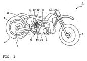
- FIG. 1 is a side view of a motorcycle having a hydraulic damping force control unit according to the present embodiment.
- FIG. 2 is a diagram showing the construction of the hydraulic damping force control unit according to the present embodiment.
- FIG. 3 is a sectional view of a damping force control valve.
- FIG. 4 is a block diagram showing the construction of the hydraulic damping force control unit according to the present embodiment.
- reference numeral 1 denotes a motorcycle according to this embodiment.
- Reference numeral 2 denotes a front wheel, 3 an engine, 4 a rear wheel, 5 a rear arm, and 6 a rear cushion unit, of the motorcycle 1.
- a hydraulic damping force control unit 11 (see FIG. 2) according to the present embodiment is used in the rear cushion unit 6.
- the rear cushion unit 6 is made up of a hydraulic shock absorber 13 having a hydraulic cylinder 12 and the hydraulic damping force control unit 11 according to the present embodiment assembled thereto, and a compression coil spring 14.
- the hydraulic cylinder 12 is constructed with a tube 15, a piston 16 movably inserted in the tube 15, a piston rod 17 connected to the piston 16, a head cover 18 which closes one end of the tube 15, and a rod cover 19 which closes the other end of the tube 15.
- the inside of the hydraulic cylinder 12 is filled with hydraulic fluid.
- the piston 16 defines the inside of the hydraulic cylinder 12 into a rod side fluid chamber 20 and a head side fluid chamber 21.
- the action of the piston rod 17 of being retracted out of the tube 15 to increase the overall length of the hydraulic cylinder 12 is described as "the hydraulic shock absorber is expanded”, and this stroke is referred to as an expansion stroke.
- the action of the piston rod 17 of being advanced into the tube 15 to reduce the overall length of the hydraulic shock absorber 11 is described as "the hydraulic shock absorber is compressed”, and this stroke is referred to as a compression stroke.
- the piston 16 is provided with a check valve 22 which allows hydraulic fluid to pass from the head side fluid chamber 21 to the rod side fluid chamber 20 only.
- An end of the hydraulic cylinder 12, on the lower side in FIG. 2, is pivotally supported on a vehicle body frame 23 (see FIG. 1) of the motorcycle 1.
- a rod end 17a of the piston rod 17 is coupled to the rear arm 5 via a link mechanism 24.
- an end of a first fluid path 25 of the hydraulic damping force control unit 11 is connected to the rod side fluid chamber 20, and an end of a second fluid path 26 is connected to the head side fluid chamber 21.
- the first fluid path 25 is provided with a damping force control valve 31 to be described later.
- the second fluid path 26 is connected to a fluid chamber 33 of an accumulator 32.
- the other end of the first fluid path 25 is connected to the second fluid path 26, between the hydraulic cylinder 15 and the accumulator 32.
- the accumulator 32 is constructed such that the fluid chamber 33 and a gas chamber 35 adjoin each other via a movable partition wall 34.
- the gas chamber 35 is filled with high-pressure gas by which pressure the hydraulic fluid in the fluid chamber 33 is urged.
- the damping force control valve 31 of which internal structure will be described specifically later, is constructed to allow hydraulic fluid to flow to the downstream side when the hydraulic pressure on the upstream side (on the cylinder 12 side) has exceeded a predetermined opening pressure.
- the opening pressure is increased and decreased by a linear solenoid 36 (see FIG. 3) provided for the damping force control valve 31.
- the linear solenoid 36 is controlled to operate by a control unit 41 (see FIG. 4) to be described later.
- the damping force control valve 31 is connected to the hydraulic cylinder 12 through the fluid paths 25 and 26 so as to be parallel with the check valve 22.
- the damping force control valve 31 increases and decreases the amount of hydraulic fluid which flows through the first fluid path 25 from the left side to the right side in FIG. 2 when the piston rod 17 of the hydraulic cylinder 12 is retracted to increase the overall length of the hydraulic shock absorber 13, to control the magnitude of damping force to be generated during that time.
- the damping force control valve 31 and the check valve 22 of the piston 16 constitute the hydraulic damping force control unit 11 according to the present embodiment.
- the damping force control unit 11 is accommodated and supported in a valve case 42 provided on a side of the rear cushion unit 6 as shown in FIG. 1.
- the control unit 41 for controlling the damping force control valve 31 is made up of piston position calculation means 43, piston speed calculation means 44, damping force calculation means 45, damping force correction means 46, a memory 47, and electric current control means 48.
- the control unit 41 is connected to the linear solenoid 36 of the damping force control valve 31, and a stroke sensor 49.
- the stroke sensor 49 in this embodiment is coupled to the rear arm 5 via a link 50 so as to detect the amount of swing of the rear arm 5.
- the piston position calculation means 43 is constructed to obtain by calculation the position of the piston 16 of the hydraulic shock absorber 13 from the amount of swing of the rear arm 5 detected by the stroke sensor 49.
- the piston speed calculation means 44 is constructed to obtain the moving speed of the piston 16 by detecting, for example at regular intervals, the position of the piston 16 obtained by the piston position calculation means 43.
- the damping force calculation means 45 is constructed to obtain by calculation a target value of damping force based on the position of the piston 16 detected by the piston position calculation means 43, the moving speed of the piston 16 detected by the piston speed calculation means 44, and a correction value stored in the memory 47.
- the correction value is set by the damping force correction means 46.
- the damping force correction means 46 is constructed to select by human operation one correction value out of plural correction values stored in the memory 47, so as to increase and decrease the damping force of the hydraulic shock absorber 13, for example according to operation by a rider.
- the target value of damping force obtained by the damping force calculation means 45 is set to be generally proportional to the moving speed of the piston 16 of the hydraulic shock absorber 13.
- the damping force control valve 31 is structured to have the linear solenoid 36 and a pilot valve 55, which will be described later, assembled to a poppet valve. That is, the damping force control valve 31 is constructed with a solenoid cover 51 formed in a bottomed cylinder, a tubular valve casing 52 secured to the opening of the solenoid cover 51, a valve element 54 fitted in a valve hole 53 in the valve casing 52 so as to be reciprocally movable, a pilot valve 55 for controlling the movement of the valve element 54, the linear solenoid 36 for urging the pilot valve 55 in the closing direction, and a compression coil spring 69.
- the linear solenoid 36, the pilot valve 55, the control unit 41, and so forth constitute the damping force setting means of the present embodiment.
- the valve element 54 is formed in a stepped bottomed cylinder, having a small diameter portion 59 formed with a seat surface 58 for seating on a valve seat 57 of the valve casing 52, and a large diameter portion 60 to be fitted with the valve hole 53, disposed coaxially with each other.
- valve hole 53 The inside of the valve hole 53 is fitted with the valve element 54 and defined by it into a fluid chamber 61 and a pilot pressure chamber 62.
- the fluid chamber 61 is in communication with an upstream portion 25a of the first fluid path 25 (on the hydraulic cylinder 12 side) through an inlet hole 63, of which opening edge on the downstream side is defined by the valve seat 57.
- the fluid chamber 61 is also in communication with a downstream portion 25b of the first fluid path 25 (on the second fluid path 26 side, or on the accumulator 32 side) through an outlet hole 64 which opens in the wall surface defining the valve hole 53.
- the pilot pressure chamber 62 is defined by walls including the inner wall surface defining the valve hole 53, the valve element 54, a pilot pressure chamber defining wall member 65 which closes an end of the valve hole 53, and a pilot valve element 67 which opens and closes a through hole 66 formed by drilling at the axial center of the wall member 65.
- the pilot pressure chamber 62 is in communication with the inlet hole 63 through a pilot path 68a passing through the axis of the small diameter portion of the valve element 54.
- the wall member 65 is formed in a bottomed cylinder having a circular bottom wall 65a opposing the valve element 54.
- the wall member 65 is fixed to the valve casing 52 with a circumferential wall 65b, provided along the outer circumference of the bottom wall 65a, located opposite the valve element 54.
- the wall member 65 is fixed as interposed between a tubular housing 68 of the linear solenoid 36 to be described later and the valve casing 52.
- the compression coil spring 69 for urging the valve element 54 in the closing direction is elastically mounted in a space between the bottom wall 65a of the wall member 65 and.an inside recess 54a of the valve element 54.
- a radially outer portion of the bottom wall 65a relative to the through hole 66 is formed by drilling with a pressure conduction path 72 for communication between the pilot pressure chamber 62 and a downstream side fluid chamber 71 which is a recess inside the circumferential wall 65b.
- the pressure conduction path 72 is formed to extend in parallel with the axis of the valve hole 53.
- the distal end of the circumferential wall 65b is formed with recessed grooves 74 which constitute a part of a communication path 73 for communication between the downstream side fluid chamber 71 and the downstream portion 25b of the first fluid path 25.
- a plurality of the recessed grooves 74 are formed to extend radially in the end surface of the circumferential wall 65b. The opening portions of the grooves are closed by the end surface of the tubular housing 68 of the linear solenoid 36.
- the communication path 73 includes the recessed grooves 74, an annular fluid chamber 75 defined between the circumferential wall 65b and the inner wall surface of the valve casing 52, a fluid hole 76 radially passing through the valve casing 52, an annular fluid chamber 77 defined between the outer circumferential surface of the valve casing 52 and the inner circumferential surface of the solenoid cover 51, and a fluid hole 79 axially passing through an outer circumferential flange 78 of the valve casing 52.
- the downstream side fluid chamber 71, the pressure conduction path 72, and the communication path 73 constitute the communication path for communication between the pilot pressure chamber and the downstream side fluid path of the present embodiment.
- the pilot valve 55 is constructed with the wall member 65, the valve element 67 located opposite the pilot pressure chamber 62 across the wall member 65, a plunger 81 of the linear solenoid 36 for supporting the valve element 67, the tubular housing 68 for supporting the plunger 81 so as to be reciprocally movable, and so forth.
- the tubular housing 68 is formed by assembling plural cylindrical members together.
- the linear solenoid 36 is constructed with the plunger 81, the tubular housing 68, a coil 82 provided on the outer side of the tubular housing 68, the solenoid cover 51 for covering the coil 82, and so forth.
- valve element 67 of the pilot valve 55 is formed with a tapered surface 83, and its other end is formed with a support shaft 84.
- the tapered surface 83 is formed to contact the opening edge of the through hole 66 over the entire circumference as the valve element 67 is moved toward the wall member 65 side.
- the support shaft 84 is fitted with and supported by the plunger 81.
- the linear solenoid 36 is constructed such that the plunger 81 is moved toward the pilot pressure chamber 62 side (toward the left side in FIG. 2) to generate urging force which pushes the valve element 67 of the pilot valve 55 in the closing direction as the coil 82 is energized, with the urging force increased and decreased according to the amount of electric current.
- the overall length of the hydraulic shock absorber 13 having the thus constructed damping force control valve 31 is increased (the hydraulic shock absorber 13 is expanded) by the downward movement of the rear wheel 4 of the motorcycle 1 relative to the vehicle body frame 23, and reduced (the hydraulic shock absorber 13 is compressed) by the movement of the rear wheel 4 in the opposite direction.
- the check valve 22 is closed which increases the hydraulic pressure in the rod side fluid chamber 20 and the upstream portion 25a of the first fluid path 25.
- the damping force control valve 31 is opened to allow hydraulic fluid to flow to the downstream side.
- the damping force control valve 31 When the damping force control valve 31 is opened in this manner, it functions as a throttle which causes the hydraulic shock absorber 13 to generate damping force.
- the magnitude of the damping force is controlled by the control unit 41 increasing and decreasing the electric current for the linear solenoid 36.
- the damping force control valve 31 When the differential pressure between the hydraulic pressure in the inlet hole 63 and that in the outlet hole 64 (in the fluid chamber 61) is small, for example when the hydraulic shock absorber 13 is at a halt, the damping force control valve 31 is closed with the valve element 54 pushed against the valve seat 57 by the elastic reaction force of the compression coil spring 69. When the hydraulic pressure in the inlet hole 63 of the damping force control valve 31 is increased by the expansion of the hydraulic shock absorber 13, that hydraulic pressure is transmitted to the pilot pressure chamber 62 through the pilot path 68a and thus the valve element 54 receives that hydraulic pressure from both the inlet hole 63 side and the pilot pressure chamber 62 side.
- the pilot valve 55 When the hydraulic pressure in the pilot pressure chamber 62 is increased as that in the inlet hole 63 is increased, and has become greater than the force which urges the valve element 67 of the pilot valve 55 in the closing direction, or in other words the urging force of the linear solenoid 36, the pilot valve 55 is opened to allow the pressurized fluid to flow out of the pilot pressure chamber 62 into the downstream side fluid chamber 71. As a result, the hydraulic pressure in the pilot pressure chamber 62 is decreased to be as low as that in the outlet hole 64. The decrease in the hydraulic pressure in the pilot pressure chamber 62 causes the pilot valve 55 to be closed.
- the valve element 54 When the hydraulic pressure in the pilot pressure chamber 62 is decreased, the valve element 54 is pushed by the hydraulic pressure in the inlet hole 63 to be moved toward the pilot pressure chamber 62 side, and the pressurized fluid in the inlet hole 63 passes through a space between the small diameter portion 59 of the valve element 54 and the valve seat 57 to flow into the fluid chamber 61.
- increasing and decreasing the hydraulic pressure in the pilot pressure chamber 62 (which is generally the same as that in the inlet hole 63) at which the pilot valve 55 is opened, by increasing and decreasing the urging force of the linear solenoid 36, can control the opening and closing movement of the valve element 54. This allows the damping force control valve 31 to control the damping force to be generated.
- the check valve 22 which has been closed so far can now open.
- the elastic reaction force and the spring constant of its return spring, the amount of valve lift, and so forth are set so as to increase the responsiveness of the check valve 22 when opened and closed, which causes the check valve 22 to have a relatively large pressure loss, compared to the first and second fluid paths 25 and 26 and so forth.
- a differential pressure is generated between the upstream side and the downstream side of the check valve 22.
- the damping force control valve 31 is on standby as closed when the hydraulic shock absorber 13 is in the compression stroke.
- the hydraulic damping force control unit 11 of this embodiment allows the hydraulic shock absorber 13 to shift from the compression stroke to the expansion stroke with the damping force control valve 31 closed.
- the hydraulic damping force control unit 11 can cause the damping force control valve 31 to generate suitable damping force from the moment when the hydraulic shock absorber 13 shifts from the compression stroke to the expansion stroke.
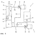
- FIG. 5 is a diagram showing the construction of a hydraulic shock absorber having two damping force control valves connected to a single hydraulic cylinder.
- FIG. 6 is a block diagram showing the construction of a control system with the two damping force control valves.
- FIG. 7 is a graph showing the operation of the hydraulic shock absorber and the damping force control valves.
- the hydraulic damping force control unit 11 of this embodiment is provided with a check valve 91 and a damping force control valve 92, disposed in parallel with each other.
- the check valve 91 is constructed to allow hydraulic fluid to flow from the accumulator 32 to the head side fluid chamber 21 in the hydraulic cylinder 15 only.
- the damping force control valve 92 is structured in the same way as the other damping force control valve 31.
- the inlet hole 63 and the outlet hole 64 of the damping force control valve 92 are connected to an upstream portion 26a and a downstream portion 26b of the second fluid path 26, respectively.
- the one provided on the first fluid path 25 and the other provided on the second fluid path 26 will be hereinafter referred to as an expansion side damping force control valve 31 and a compression side damping force control valve 92, respectively.
- the linear solenoid 36 of the compression side damping force control valve 92 is connected to the electric current control means 48 as shown in FIG. 6, and controlled to operate by the control unit 41 in the same manner as the linear solenoid 36 of the expansion side damping force control valve 31 is controlled.
- the expansion side damping force control valve 31 when the hydraulic shock absorber 13 is in the expansion stroke, pressurized fluid flows into the head side fluid chamber 21 through the first fluid path 25 and the expansion side damping force control valve 31, and also into the head side fluid chamber 21 through the check valve 91 from the accumulator 32.
- the expansion side damping force control valve 31 generates damping force.
- the hydraulic pressure on the upstream side (on the accumulator 32 side) of the check valve 91 is relatively increased, and that hydraulic pressure is transmitted from the outlet hole 64 to the pilot pressure chamber 62 of the compression side damping force control valve 92.
- the compression side damping force control valve 92 is on standby as closed when the hydraulic shock absorber 13 is in the expansion stroke.
- the hydraulic pressure on the upstream side (on the head side fluid chamber 21 side) of the check valve 22 of the piston 16 is relatively increased, and that hydraulic pressure is transmitted from the outlet hole 64 to the pilot pressure chamber 62 of the expansion side damping force control valve 31.
- the expansion side damping force control valve 31 is on standby as closed when the hydraulic shock absorber 13 is in the compression stroke.
- FIG. 7 The operation of the hydraulic damping force control unit 11 of this embodiment is shown in FIG. 7.
- a solid line A indicates changes in the moving direction of the piston 16 of the hydraulic shock absorber 13 (upper and lower sides correspond to expansion and compression, respectively)
- a solid line B indicates changes in the moving speed of the piston 16
- a broken line C indicates changes in the damping force
- a solid line D indicates changes in the opening degree of the valve element 54 of the expansion side damping force control valve 31
- a solid line E indicates changes in the opening degree of the valve element 54 of the compression side damping force control valve 92.
- symbol F corresponds to the period when the hydraulic shock absorber 13 is in the expansion stroke
- symbol G corresponds to the period when the hydraulic shock absorber 13 is in the compression stroke.
- the expansion side damping force control valve 31 is fully closed when the hydraulic shock absorber 13 is in the compression stroke G.
- the expansion side damping force control valve of a conventional hydraulic shock absorber is opened during the compression stroke G as indicated by a dot dashed line d in FIG. 7, which causes the damping force to be unstable during the period indicated by symbol b in the same drawing.
- the construction of this embodiment allows the expansion side damping force control valve 31 to be on standby as closed during the compression stroke G.
- the expansion side damping force control valve 92 is fully closed when the hydraulic shock absorber 13 is in the expansion stroke F.
- the compression side damping force control valve of a conventional hydraulic shock absorber is opened during the expansion stroke F as indicated by a dot dashed line e in FIG. 7, which causes the damping force to be unstable during the period indicated by symbol a in the same drawing.
- the construction of this embodiment allows the compression side damping force control valve 92 to be on standby as closed during the expansion stroke F.
- the pressure conduction path 72 of the expansion side damping force control valve 31 and the compression side damping force control valve 92 can be provided in the pilot valve 55 as shown in FIG. 8.
- FIG. 8 is a sectional view of another embodiment of the damping force control valve.
- components identical or equivalent to those described in relation to FIGs. 1 to 7 are denoted by the same reference numerals, and their detailed descriptions will not be repeated as appropriate.
- valve element 67 of the pilot valve 55 is formed with pressure conduction paths 72a which are notches or cutouts provided in portions of the tapered surface 83 which contact the opening edge of the through hole 66.
- a plurality of the pressure conduction paths 72a are provided at intervals around the circumference of the valve element 67.
- the hydraulic damping force control unit according to the present embodiment has been illustrated as being applied to a rear cushion unit for a motorcycle.
- the hydraulic damping force control unit according to the present embodiment can also be applied to a telescopic front fork of vehicles such as motorcycles or three wheelers. Such an embodiment will be described in detail with reference to FIG. 9.
- FIG. 9 is a diagram showing the construction of a front fork having the hydraulic damping force control unit according to the present embodiment.
- components identical or equivalent to those described in relation to FiGs. 1 to 8 are denoted by the same reference numerals, and their detailed descriptions will not be repeated as appropriate.
- a front fork 101 is constructed with paired left and right hydraulic shock absorbers 102 and 103, paired left and right compression coil springs 104 and 105, an under bracket 107 and an upper bracket 108 coupling the left and right hydraulic shock absorbers 102 and 103 with each other and connected to a steering shaft 106, and so forth.
- the hydraulic shock absorbers 102 and 103 include an outer tube 111 fixed to the under bracket 107 and the upper bracket 108, and an inner wall 112 movably fitted and inserted in the outer tube 111.
- the inside of the outer tube 111 and the inner tube 112 is filled with hydraulic fluid to a fluid level L.
- a hydraulic cylinder 12 is fixed inside the inner tube 112.
- the inner tube 112 supports a wheel shaft 113 of the front wheel 2.
- the compression coil springs 104 and 105 are elastically mounted between the upper end of the hydraulic cylinder 15 and the upper end of the outer tube 111.
- the piston rod 17 of the hydraulic cylinder 15 is fixed to the upper end of the outer tube 111.
- the rod side fluid chamber 20 of the hydraulic cylinder 15 located on the left side in FIG. 9 is connected to a fluid chamber 114 in the inner tube 112.
- the head side fluid chamber 21 of the same hydraulic cylinder 15 is connected to the fluid chamber 114 through the second fluid path 26 and the compression side damping force control valve 92.
- the hydraulic cylinder 15 is provided with the check valve 91 which allows hydraulic fluid to flow from the fluid chamber 114 into the head side fluid chamber 21 only, disposed between the head side fluid chamber 21 and the fluid chamber 114 in the inner tube 112.
- the rod side fluid chamber 20 of the hydraulic cylinder 15 located on the right side in FIG. 9 is connected to the head side fluid chamber 21 and a fluid chamber 114 in the inner tube 112 through the first fluid path 25 and the expansion side damping force control valve 31.
- the piston 16 of the right hydraulic cylinder 15 is provided with the check valve 22 which allows hydraulic fluid to flow from the head side fluid chamber 21 to the rod side fluid chamber 20 only.
- the left hydraulic shock absorber 102 and the right hydraulic shock absorber 103 of the front fork 101 move in the same direction at the same time.
- the compression side damping force control valve 92 of the left hydraulic shock absorber 102 generates damping force.
- the expansion side damping force control valve 31 of the right hydraulic shock absorber 103 generates damping force.
- the expansion side damping force control valve 31 is on standby as closed, and when they are in the expansion stroke, the compression side damping force control valve 92 is on standby as closed.
- damping force can be generated in both the compression stroke and the expansion stroke, using the two hydraulic cylinders 15 and 15 and the two damping force control units 11 and 11.
- the size of pistons and rods can be selected independently of each other, between the hydraulic shock absorber 102 which generates damping force in the compression stroke and the hydraulic shock absorber 103 which generates damping force in the expansion stroke.
- the hydraulic damping force control unit according to the present embodiment has been illustrated as being connected to a hydraulic cylinder.
- the hydraulic damping force control unit according to the present embodiment can also be applied to a rotary damper as shown in FIG. 10.
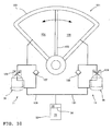
- FIG. 10 is a diagram showing the construction of another embodiment where the hydraulic damping force control unit according to the present embodiment is used in a rotary damper.
- components identical or equivalent to those described in relation to FIGS. 1 to 9 are denoted by the same reference numerals, and their detailed descriptions will not be repeated as appropriate.
- a rotary damper 121 includes a housing 122 inside of which is filled with hydraulic fluid, and a vane 123 provided in the housing 122 for swinging movement.
- the vane 123 constitutes the movable partition wall of the invention of Claim 4.
- the inside of the housing 122 is defined by the vane 123 into a first fluid chamber 124 and a second fluid chamber 125.
- the vane 123 is structured to swing together with a member to be shock absorbed (not shown) such as, for example, a steering shaft of a motorcycle.
- the first fluid chamber 124 is connected to the fluid chamber 33 of the accumulator 32, through a first damping force control valve 126, a first check valve 127, and a first fluid path 128.
- the second fluid chamber 125 is also connected to the fluid chamber 33 of the accumulator 32, through a second damping force control valve 129, a second check valve 130, and a second fluid path 131.
- the first damping force control valve 126 and the first check valve 127 are connected in parallel with each other, with their one ends connected to the first fluid chamber 124 and their other ends connected to the first fluid path 128.
- the second damping force control valve 129 and the second check valve 130 are also connected in parallel with each other, with their one ends connected to the second fluid chamber 125 and their other ends connected to the second fluid path 131.
- the first damping force control valve 126 and the second damping force control valve 129 are structured in the same way as the expansion side damping force control valve 31 (compression side damping force control valve 92) used in the first to fourth embodiments.
- Their inlet hole 63 is connected to the first fluid chamber 124 or the second fluid chamber 125.
- the first and second check valves 127 and 130 are constructed to allow hydraulic fluid to flow from the first fluid path 128 or the second fluid path 131 to the first fluid chamber 124 or the second fluid chamber 125 only.
- the accumulator 32 is provided to compensate for volume changes of hydraulic fluid due to temperature changes.
- the first damping force control valve 126 generates damping force in a stroke where the vane 123 swings toward the left in the drawing to reduce the capacity of the first fluid chamber 124
- the second damping force control valve 129 generates damping force in a stroke where the vane 123 swings toward the right in the drawing to reduce the capacity of the second fluid chamber 125.
- hydraulic fluid which has passed through the second check valve 130 flows into the second fluid chamber 125.
- the second damping force control valve 129 is closed.
- the second damping force control valve 129 generates damping force right from the moment when the moving direction of the vane 123 has changed and the vane 123 has begun to move toward the right in the drawing.
- the rotary damper 121 also produces the same effect as the foregoing embodiments.
- a hydraulic damping force control unit including: a poppet valve for opening and closing a fluid path; a pilot pressure chamber defined from the fluid path by a valve element of the poppet valve; damping force setting means for increasing and decreasing the hydraulic pressure in the pilot pressure chamber; and a check valve provided on the fluid path in parallel with the poppet valve to allow pressurized fluid to flow from the downstream side to the upstream side of the poppet valve only, in which the hydraulic damping force control unit further includes a communication path for communication between the fluid path downstream of the poppet valve and the pilot pressure chamber.
- the relatively high hydraulic pressure can be utilized to keep the poppet valve closed while it is on standby. Consequently, the poppet valve, for example connected to a hydraulic cylinder, can generate suitable damping force right from the moment when the hydraulic cylinder has shifted from the compression stroke to the expansion stroke or vice versa.
- the hydraulic shock absorber has the hydraulic damping force control unit in at least one of a fluid path through which hydraulic fluid flows out of a rod side fluid chamber of a hydraulic cylinder and a fluid path through which hydraulic fluid flows out of a head side fluid chamber of the hydraulic cylinder.
- the poppet valve of a pressure control unit that is on standby can be kept closed when the piston starts to move after passing over dead center, for example when the hydraulic cylinder shifts from the compression stroke to the expansion stroke or vice versa.
- a hydraulic shock absorber which generates constant and suitable damping force.
- a front fork for a vehicle having the hydraulic damping force control unit in each of paired left and right hydraulic shock absorbers, in which the damping force control unit is connected to a rod side fluid chamber in one of the paired left and right hydraulic shock absorbers, and the damping force control unit is connected to a head side fluid chamber in the other of the paired left and right hydraulic shock absorbers.
- the poppet valve of the damping force control unit that is connected to the head side fluid chamber is on standby as closed, and when the hydraulic shock absorber is compressed, the poppet valve of the damping force control unit that is connected to the rod side fluid chamber is on standby as closed. Therefore, the poppet valve of a pressure control unit that is on standby can be kept closed when the piston starts to move after passing over dead center, for example when the hydraulic cylinder of the hydraulic shock absorber shifts from the compression stroke to the expansion stroke or vice versa.
- damping force can be generated in both the compression stroke and the expansion stroke, using the two hydraulic cylinders and the two damping force control units.
- the size of pistons and rods can be selected independently between the hydraulic shock absorber which generates damping force in the compression stroke and the hydraulic shock absorber which generates damping force in the expansion stroke. This produces an additional effect that the degree of freedom in setting the maximum damping force and the maximum working pressure is increased.
- a hydraulic rotary damper having the hydraulic damping force control unit connected to at least one of two fluid chambers defined by a movable partition wall which swings in conjunction with a member to be shock absorbed.
- the poppet valve of the damping force control unit that is connected to the one fluid chamber is on standby as closed, and when the movable partition wall is moved from the other fluid chamber side toward the one fluid chamber side, the poppet valve of the damping force control unit that is connected to the other fluid chamber is on standby as closed. Therefore, the poppet valve of a pressure control unit that is on standby can be closed when the moving direction of the movable partition wall of the rotary damper is changed.
- a rotary damper which generates constant and suitable damping force.
- a damping force control valve 31 including a poppet valve for opening and closing a first fluid path 25 is provided.
- a pilot pressure chamber 62 defined from the fluid path 25 by a valve element 54 of the damping force control valve 31 is provided.
- a linear solenoid 36 and a pilot valve 55 for increasing and reducing the hydraulic pressure in the pilot pressure chamber 62 are provided.
- a check valve 22 disposed in parallel with the damping force control valve 31 is provided in a piston 16.
- a communication path for communication between the first fluid path 25 downstream of the damping force control valve 31 and the pilot pressure chamber 62 is provided.
Landscapes
- Engineering & Computer Science (AREA)
- General Engineering & Computer Science (AREA)
- Mechanical Engineering (AREA)
- Fluid-Damping Devices (AREA)
- Vibration Prevention Devices (AREA)
Abstract
The present invention relates to a hydraulic damping force control unit comprising a damping force control valve (31) having a valve element (54) for opening and closing a first fluid path (25) and defining a pilot pressure chamber (62), damping force setting means for increasing and decreasing a hydraulic pressure in the pilot pressure chamber, and a check valve (22) disposed in a fluid path in parallel with the damping force control valve to allow pressurized fluid to flow from a downstream side to an upstream side of the damping force control valve only, and a communication path for communication between the first fluid path downstream of the damping force control valve and the pilot pressure chamber.
Description
- The present invention relates to a hydraulic damping force control unit, preferably applied to a hydraulic shock absorber, a front fork for a vehicle, and a hydraulic rotary damper which use a poppet valve to generate damping force.
- One example of conventional hydraulic shock absorber having a damping force control valve is disclosed in JP-B-3306526. The hydraulic shock absorber disclosed in JP-B-3306526 is for use in suspension systems of vehicles, and constructed with a hydraulic cylinder provided between the wheel side and the vehicle body frame side, damping force control valves provided in a hydraulic circuit of the hydraulic cylinder, and so forth.
- The hydraulic cylinder is constructed with a cylinder body filled with hydraulic fluid, a piston which defines the inside of the cylinder body into a head side fluid chamber and a rod side fluid chamber, and so forth. The head side fluid chamber and the rod side fluid chamber are connected with each other through a hydraulic circuit including valves and an accumulator.
- The hydraulic circuit includes a head side fluid path which connects the head side fluid chamber to the accumulator, a rod side fluid path which connects the rod side fluid chamber to the accumulator, a head side check valve provided on the head side fluid path to allow hydraulic fluid to flow toward the head side fluid chamber only, a rod side check valve provided on the rod side fluid path to allow hydraulic fluid to flow toward the rod side fluid chamber only, a compression side damping force control valve provided in parallel with the head side check valve, an expansion side damping force control valve provided in parallel with the rod side check valve, and so forth.
- The compression side damping force control valve and the expansion side damping force control valve include a poppet valve, which is constructed such that its valve element to be described later is opened, when the check valve regulates the flow of hydraulic fluid to increase the hydraulic pressure, to generate damping force. The damping force control valves include a hydraulic fluid inlet connected to a fluid path located on the hydraulic cylinder side with respect to the check valve, a valve hole of which one end is located at the opening of the hydraulic fluid inlet, a hydraulic fluid outlet opening in the wall surface of the valve hole and connected to a fluid path located opposite the hydraulic cylinder with respect to the check valve, a valve element fitted and inserted in the valve hole so as to be reciprocally movable, a compression coil spring for urging the valve element in the closing direction (toward the hydraulic fluid inlet side), a pilot pressure chamber defined in the valve hole by the valve element, and so forth.
- The valve element is formed in a cylinder having a tapered portion at its distal end. The tapered portion faces the hydraulic fluid inlet from inside the valve hole, and is formed to seat on a valve seat which is the opening edge of the hydraulic fluid inlet. When the damping force control valve is fully closed with the tapered portion seating on the valve seat, a portion of the tapered portion more centrally than the valve seat receives the hydraulic pressure at the hydraulic fluid inlet, and the outer circumference of the tapered portion located more internally of the valve hole than the valve seat receives the hydraulic pressure at the hydraulic fluid outlet.
- The pilot pressure chamber is connected through a pilot path to a fluid path on the hydraulic cylinder side with respect to the check valve. At the middle of the pilot path is provided a relief valve which allows hydraulic fluid to flow to a fluid path located opposite the hydraulic cylinder with respect to the check valve when the hydraulic pressure in the pilot path has been increased to a predetermined value or higher.
- According to the damping force control valve, when the hydraulic pressure in the fluid path located on the hydraulic cylinder side from the relief valve has exceeded the predetermined value to open the relief valve, the hydraulic pressure in the pilot pressure chamber is reduced, which results in the valve element being opened. As the valve element opens, hydraulic fluid passes through a space between the valve seat and the tapered portion to flow from the hydraulic fluid inlet into the valve hole, and then passes through the valve hole to be discharged through the hydraulic fluid outlet. At this time, the damping force control valve functions as a throttle to generate damping force.
- Hydraulic fluid discharged through the hydraulic fluid outlet flows toward the accumulator or the side of the other fluid chamber of the cylinder.
- When the hydraulic shock absorber is in an expansion stroke, for example, the rod side check valve is closed and thus hydraulic fluid passes through the expansion side damping force control valve and then through the head side check valve to flow into the head side fluid chamber.
- Regarding the check valve, the elastic reaction force and the spring constant of its return spring are set to be higher, and the amount of valve lift is set to be smaller, in order to increase the responsiveness of the check valve when opened and closed. Therefore, a differential pressure is generated between the upstream side and the downstream side of the check valve when hydraulic fluid passes through it.
- At this time, the pressure (differential pressure) which has occurred at the head side check valve is transmitted through the hydraulic fluid outlet of the compression side damping force control valve into the valve hole, which presses the outer circumference of the tapered portion in the opening direction to cause the valve element to be opened. In other words, when the hydraulic shock absorber is in the expansion stroke, the damping force control valve that should be on standby as closed is unfavorably opened.
- When the frequency and amplitude of vibration of a wheel are relatively small, there is enough time before the expansion stroke of the hydraulic shock absorber ends. Thus, the flow rate of hydraulic fluid through the compression side damping force control valve and the differential pressure are gradually reduced, and along with that the hydraulic pressure is overcome by the elastic reaction force of the compression coil spring which is urging the valve element in the closing direction. This causes the valve element to be closed before the piston of the hydraulic shock absorber reaches dead center.
- When the frequency and amplitude of vibration of a wheel are relatively large, however, the flow rate of pressurized fluid through the head side check valve is high and hence the differential pressure is large. This causes the compression side damping force control valve to be opened to a relatively large degree. Thus, occasionally, there is not enough time for the valve element to be closed before the piston of the hydraulic shock absorber reaches dead center in the expansion stroke and the valve is kept opened even after the hydraulic shock absorber has shifted to a compression stroke.
- If the compression side damping force control valve is opened when the hydraulic shock absorber has shifted from the expansion stroke to the compression stroke as described above, the compression side damping force control valve cannot generate a magnitude of damping force necessary at the moment. When the hydraulic shock absorber has shifted to the compression stroke, the hydraulic pressure on the upstream side of the compression side damping force control valve (or the hydraulic pressure in the hydraulic fluid inlet and in the pilot pressure chamber) is gradually increased. The compression side damping force control valve is abruptly closed from its opened state by the elastic damping force of the compression coil spring and the hydraulic pressure in the pilot pressure chamber, and then the valve element is gradually opened to generate damping force.
- In other words, the damping force to be generated by the compression side damping force control valve at this time is unstable (the damping force waveform is disordered. In order for the damping force to be increased according to the increase in the speed of the hydraulic shock absorber, the damping force control valve needs to be closed when the piston starts to move. The above description is based on the case where the hydraulic shock absorber shifts from the expansion stroke to the compression stroke. On the contrary, when the hydraulic shock absorber shifts from the compression stroke to the expansion stroke, the expansion side damping force control valve is on standby as opened, which causes the same problem as described above.
- The damping force of such a conventional hydraulic shock absorber changes as shown for example in FIG. 11. FIG. 11 is a graph showing the relationship between the moving speed of a piston and the damping force. As shown in FIG. 11, because the compression side damping force control valve, which should be closed, is opened when the hydraulic shock absorber has shifted from the expansion stroke to the compression stroke, the damping force is unstable in the range indicated by symbol a in FIG. 11. Also, because the expansion side damping force control valve, which should be closed, is opened when the hydraulic shock absorber has shifted from the compression stroke to the expansion stroke, the damping force is unstable in the range indicated by symbol b in FIG. 11.
- The present invention has been made to solve such problems, and therefore has an object to provide a hydraulic damping force control unit generating damping force properly by keeping a damping force control valve closed surely when a piston of a hydraulic shock absorber starts to move from compression side dead center or expansion side dead center.
- This objective is solved by a hydraulic damping force control unit comprising a damping force control valve having a valve element for opening and closing a first fluid path and defining a pilot pressure chamber, damping force setting means for increasing and decreasing a hydraulic pressure in the pilot pressure chamber, and a check valve disposed in a fluid path in parallel with the damping force control valve to allow pressurized fluid to flow from a downstream side to an upstream side of the damping force control valve only, and a communication path for communication between the first fluid path downstream of the damping force control valve and the pilot pressure chamber.
- The damping force control valve preferably comprises a poppet valve for opening and closing the first fluid path, wherein the pilot pressure chamber may be defined from the first fluid path by a valve element of the poppet valve, wherein the check valve may be provided on the fluid path in parallel with the poppet valve to allow pressurized fluid to flow from a downstream side to an upstream side of the poppet valve only, and wherein the communication path may provide communication between the first fluid path downstream of the poppet valve and the pilot pressure chamber.
- The hydraulic damping force control unit may be provided with a pilot valve for controlling the movement of the valve element and a linear solenoid for urging the pilot valve in the closing direction, both being assembled to form the poppet valve.
- The damping force setting means may comprise the linear solenoid, the pilot valve, and a control unit.
- According to a preferred embodiment, the hydraulic damping force control unit is provided with a valve casing accommodating the valve element, and comprising an inlet hole in communication with an upstream portion of the damping force control valve, and an outlet hole in communication with an downstream portion of the damping force control valve, and is provided with by a first fluid chamber communicating with the upstream portion and the downstream portion via the inlet hole and the outlet hole, respectively.
- The pilot pressure chamber may be at least partially defined by a recess formed in the valve element on an opposite side to the first fluid chamber, wherein a pilot path may provide fluid communication between said fluid chamber and said pilot pressure chamber.
- According to a further preferred embodiment, the hydraulic damping force control unit may be provided with a pilot valve element adapted to open and close a through hole providing communication between the pilot pressure chamber and a second fluid chamber provided on a downstream side of the pilot pressure chamber, and which constitutes a part of a communication path for communication with said downstream portion of the damping force control valve.
- Further, preferably there is provided a hydraulic shock absorber having the hydraulic damping force control unit according to one of the above embodiments in at least one of a fluid path through which hydraulic fluid flows out of a rod side fluid chamber of a hydraulic cylinder and a fluid path through which hydraulic fluid flows out of a head side fluid chamber of the hydraulic cylinder.
- Still further, preferably there is provided a front fork for a vehicle having the hydraulic damping force control unit according to one of the above embodiments in each of paired left and right hydraulic shock absorbers, wherein the damping force control unit is connected to a rod side fluid chamber in one of the paired left and right hydraulic shock absorbers, and the damping force control unit is connected to a head side fluid chamber in the other of the paired left and right hydraulic shock absorbers.
- Yet further, preferably there is provided a hydraulic rotary damper having the hydraulic damping force control unit according to one of the above embodiments connected to at least one of two fluid chambers defined by a movable partition wall which swings in conjunction with a member to be shock absorbed.
- In the following, the present invention is explained in greater detail with respect to several embodiments thereof in conjunction with the accompanying drawings, wherein:
- FIG. 1
- is a side view of a motorcycle having a first embodiment of a hydraulic damping force control unit,
- FIG. 2
- is a diagram showing the construction of the hydraulic damping force control unit according to the present embodiment,
- FIG. 3
- is a sectional view of a damping force control valve,
- FIG. 4
- is a block diagram showing the construction of the hydraulic damping force control unit according to the present embodiment,
- FIG. 5
- is a diagram showing the construction of a hydraulic shock absorber having two damping force control valves connected to a single hydraulic cylinder,
- FIG. 6
- is a block diagram showing the construction of a control system with the two damping force control valves,
- FIG. 7
- is a graph showing the operation of the hydraulic shock absorber and the damping force control valves,
- FIG. 8
- is a sectional view of another embodiment of the damping force control valve,
- FIG. 9
- is a diagram showing the construction of a front fork having the hydraulic damping force control unit according to the present embodiment,
- FIG. 10
- is a diagram showing the construction of another embodiment where the hydraulic damping force control unit according to the present embodiment is used in a rotary damper, and
- FIG. 11
- is a graph showing the relationship between the moving speed of a piston and the damping force.
- An embodiment of a hydraulic damping force control unit will be hereinafter described in detail with reference to FIGs. 1 through 3. The description will be based on an example where the hydraulic damping force control unit according to the present embodiment is applied to a rear cushion unit of a motorcycle.
- FIG. 1 is a side view of a motorcycle having a hydraulic damping force control unit according to the present embodiment. FIG. 2 is a diagram showing the construction of the hydraulic damping force control unit according to the present embodiment. FIG. 3 is a sectional view of a damping force control valve. FIG. 4 is a block diagram showing the construction of the hydraulic damping force control unit according to the present embodiment.
- In the drawings,
reference numeral 1 denotes a motorcycle according to this embodiment.Reference numeral 2 denotes a front wheel, 3 an engine, 4 a rear wheel, 5 a rear arm, and 6 a rear cushion unit, of themotorcycle 1. In themotorcycle 1, a hydraulic damping force control unit 11 (see FIG. 2) according to the present embodiment is used in therear cushion unit 6. - As shown in FIGS. 1 and 2, the
rear cushion unit 6 is made up of ahydraulic shock absorber 13 having ahydraulic cylinder 12 and the hydraulic dampingforce control unit 11 according to the present embodiment assembled thereto, and acompression coil spring 14. - The
hydraulic cylinder 12 is constructed with atube 15, apiston 16 movably inserted in thetube 15, apiston rod 17 connected to thepiston 16, ahead cover 18 which closes one end of thetube 15, and arod cover 19 which closes the other end of thetube 15. The inside of thehydraulic cylinder 12 is filled with hydraulic fluid. - The
piston 16 defines the inside of thehydraulic cylinder 12 into a rodside fluid chamber 20 and a headside fluid chamber 21. In this embodiment, the action of thepiston rod 17 of being retracted out of thetube 15 to increase the overall length of thehydraulic cylinder 12 is described as "the hydraulic shock absorber is expanded", and this stroke is referred to as an expansion stroke. On the other hand, the action of thepiston rod 17 of being advanced into thetube 15 to reduce the overall length of thehydraulic shock absorber 11 is described as "the hydraulic shock absorber is compressed", and this stroke is referred to as a compression stroke. - The
piston 16 is provided with acheck valve 22 which allows hydraulic fluid to pass from the headside fluid chamber 21 to the rodside fluid chamber 20 only. - An end of the
hydraulic cylinder 12, on the lower side in FIG. 2, is pivotally supported on a vehicle body frame 23 (see FIG. 1) of themotorcycle 1. On the other hand, arod end 17a of thepiston rod 17 is coupled to therear arm 5 via alink mechanism 24. - As shown in FIG. 2, an end of a first
fluid path 25 of the hydraulic dampingforce control unit 11 according to the present embodiment is connected to the rodside fluid chamber 20, and an end of a secondfluid path 26 is connected to the headside fluid chamber 21. The firstfluid path 25 is provided with a dampingforce control valve 31 to be described later. The secondfluid path 26 is connected to afluid chamber 33 of anaccumulator 32. The other end of the firstfluid path 25 is connected to the secondfluid path 26, between thehydraulic cylinder 15 and theaccumulator 32. Theaccumulator 32 is constructed such that thefluid chamber 33 and agas chamber 35 adjoin each other via amovable partition wall 34. Thegas chamber 35 is filled with high-pressure gas by which pressure the hydraulic fluid in thefluid chamber 33 is urged. - The damping
force control valve 31, of which internal structure will be described specifically later, is constructed to allow hydraulic fluid to flow to the downstream side when the hydraulic pressure on the upstream side (on thecylinder 12 side) has exceeded a predetermined opening pressure. The opening pressure is increased and decreased by a linear solenoid 36 (see FIG. 3) provided for the dampingforce control valve 31. Thelinear solenoid 36 is controlled to operate by a control unit 41 (see FIG. 4) to be described later. - The damping
force control valve 31 is connected to thehydraulic cylinder 12 through thefluid paths check valve 22. The dampingforce control valve 31 increases and decreases the amount of hydraulic fluid which flows through the firstfluid path 25 from the left side to the right side in FIG. 2 when thepiston rod 17 of thehydraulic cylinder 12 is retracted to increase the overall length of thehydraulic shock absorber 13, to control the magnitude of damping force to be generated during that time. The dampingforce control valve 31 and thecheck valve 22 of thepiston 16 constitute the hydraulic dampingforce control unit 11 according to the present embodiment. The dampingforce control unit 11 is accommodated and supported in avalve case 42 provided on a side of therear cushion unit 6 as shown in FIG. 1. - As shown in FIG. 4, the
control unit 41 for controlling the dampingforce control valve 31 is made up of piston position calculation means 43, piston speed calculation means 44, damping force calculation means 45, damping force correction means 46, amemory 47, and electric current control means 48. Thecontrol unit 41 is connected to thelinear solenoid 36 of the dampingforce control valve 31, and astroke sensor 49. As shown in FIG. 1, thestroke sensor 49 in this embodiment is coupled to therear arm 5 via alink 50 so as to detect the amount of swing of therear arm 5. - The piston position calculation means 43 is constructed to obtain by calculation the position of the
piston 16 of thehydraulic shock absorber 13 from the amount of swing of therear arm 5 detected by thestroke sensor 49. - The piston speed calculation means 44 is constructed to obtain the moving speed of the
piston 16 by detecting, for example at regular intervals, the position of thepiston 16 obtained by the piston position calculation means 43. - The damping force calculation means 45 is constructed to obtain by calculation a target value of damping force based on the position of the
piston 16 detected by the piston position calculation means 43, the moving speed of thepiston 16 detected by the piston speed calculation means 44, and a correction value stored in thememory 47. The correction value is set by the damping force correction means 46. The damping force correction means 46 is constructed to select by human operation one correction value out of plural correction values stored in thememory 47, so as to increase and decrease the damping force of thehydraulic shock absorber 13, for example according to operation by a rider. - The target value of damping force obtained by the damping force calculation means 45 is set to be generally proportional to the moving speed of the
piston 16 of thehydraulic shock absorber 13. - The specific structure of the damping
force control valve 31 will be described in detail with reference to FIG. 3. The dampingforce control valve 31 is structured to have thelinear solenoid 36 and apilot valve 55, which will be described later, assembled to a poppet valve. That is, the dampingforce control valve 31 is constructed with asolenoid cover 51 formed in a bottomed cylinder, atubular valve casing 52 secured to the opening of thesolenoid cover 51, avalve element 54 fitted in avalve hole 53 in thevalve casing 52 so as to be reciprocally movable, apilot valve 55 for controlling the movement of thevalve element 54, thelinear solenoid 36 for urging thepilot valve 55 in the closing direction, and acompression coil spring 69. Thelinear solenoid 36, thepilot valve 55, thecontrol unit 41, and so forth constitute the damping force setting means of the present embodiment. - The
valve element 54 is formed in a stepped bottomed cylinder, having asmall diameter portion 59 formed with aseat surface 58 for seating on avalve seat 57 of thevalve casing 52, and alarge diameter portion 60 to be fitted with thevalve hole 53, disposed coaxially with each other. - The inside of the
valve hole 53 is fitted with thevalve element 54 and defined by it into afluid chamber 61 and apilot pressure chamber 62. Thefluid chamber 61 is in communication with anupstream portion 25a of the first fluid path 25 (on thehydraulic cylinder 12 side) through aninlet hole 63, of which opening edge on the downstream side is defined by thevalve seat 57. Thefluid chamber 61 is also in communication with adownstream portion 25b of the first fluid path 25 (on the secondfluid path 26 side, or on theaccumulator 32 side) through anoutlet hole 64 which opens in the wall surface defining thevalve hole 53. - The
pilot pressure chamber 62 is defined by walls including the inner wall surface defining thevalve hole 53, thevalve element 54, a pilot pressure chamber definingwall member 65 which closes an end of thevalve hole 53, and apilot valve element 67 which opens and closes a throughhole 66 formed by drilling at the axial center of thewall member 65. Thepilot pressure chamber 62 is in communication with theinlet hole 63 through a pilot path 68a passing through the axis of the small diameter portion of thevalve element 54. - The
wall member 65 is formed in a bottomed cylinder having acircular bottom wall 65a opposing thevalve element 54. Thewall member 65 is fixed to thevalve casing 52 with acircumferential wall 65b, provided along the outer circumference of thebottom wall 65a, located opposite thevalve element 54. Thewall member 65 is fixed as interposed between atubular housing 68 of thelinear solenoid 36 to be described later and thevalve casing 52. Thecompression coil spring 69 for urging thevalve element 54 in the closing direction is elastically mounted in a space between thebottom wall 65a of thewall member 65 and.an insiderecess 54a of thevalve element 54. - A radially outer portion of the
bottom wall 65a relative to the through hole 66 (on the lower side in FIG. 3) is formed by drilling with apressure conduction path 72 for communication between thepilot pressure chamber 62 and a downstreamside fluid chamber 71 which is a recess inside thecircumferential wall 65b. Thepressure conduction path 72 is formed to extend in parallel with the axis of thevalve hole 53. The distal end of thecircumferential wall 65b is formed with recessedgrooves 74 which constitute a part of acommunication path 73 for communication between the downstreamside fluid chamber 71 and thedownstream portion 25b of the firstfluid path 25. - A plurality of the recessed
grooves 74 are formed to extend radially in the end surface of thecircumferential wall 65b. The opening portions of the grooves are closed by the end surface of thetubular housing 68 of thelinear solenoid 36. Thecommunication path 73 includes the recessedgrooves 74, anannular fluid chamber 75 defined between thecircumferential wall 65b and the inner wall surface of thevalve casing 52, afluid hole 76 radially passing through thevalve casing 52, anannular fluid chamber 77 defined between the outer circumferential surface of thevalve casing 52 and the inner circumferential surface of thesolenoid cover 51, and afluid hole 79 axially passing through an outercircumferential flange 78 of thevalve casing 52. The downstreamside fluid chamber 71, thepressure conduction path 72, and thecommunication path 73 constitute the communication path for communication between the pilot pressure chamber and the downstream side fluid path of the present embodiment. - The
pilot valve 55 is constructed with thewall member 65, thevalve element 67 located opposite thepilot pressure chamber 62 across thewall member 65, aplunger 81 of thelinear solenoid 36 for supporting thevalve element 67, thetubular housing 68 for supporting theplunger 81 so as to be reciprocally movable, and so forth. Thetubular housing 68 is formed by assembling plural cylindrical members together. Thelinear solenoid 36 is constructed with theplunger 81, thetubular housing 68, acoil 82 provided on the outer side of thetubular housing 68, thesolenoid cover 51 for covering thecoil 82, and so forth. - One end of the
valve element 67 of thepilot valve 55 is formed with atapered surface 83, and its other end is formed with asupport shaft 84. The taperedsurface 83 is formed to contact the opening edge of the throughhole 66 over the entire circumference as thevalve element 67 is moved toward thewall member 65 side. Thesupport shaft 84 is fitted with and supported by theplunger 81. - The
linear solenoid 36 is constructed such that theplunger 81 is moved toward thepilot pressure chamber 62 side (toward the left side in FIG. 2) to generate urging force which pushes thevalve element 67 of thepilot valve 55 in the closing direction as thecoil 82 is energized, with the urging force increased and decreased according to the amount of electric current. - The overall length of the
hydraulic shock absorber 13 having the thus constructed dampingforce control valve 31 is increased (thehydraulic shock absorber 13 is expanded) by the downward movement of therear wheel 4 of themotorcycle 1 relative to thevehicle body frame 23, and reduced (thehydraulic shock absorber 13 is compressed) by the movement of therear wheel 4 in the opposite direction. For example, when thehydraulic shock absorber 13 is to be expanded, thecheck valve 22 is closed which increases the hydraulic pressure in the rodside fluid chamber 20 and theupstream portion 25a of the firstfluid path 25. When that hydraulic pressure has exceeded the opening pressure for the dampingforce control valve 31, the dampingforce control valve 31 is opened to allow hydraulic fluid to flow to the downstream side. When the dampingforce control valve 31 is opened in this manner, it functions as a throttle which causes thehydraulic shock absorber 13 to generate damping force. The magnitude of the damping force is controlled by thecontrol unit 41 increasing and decreasing the electric current for thelinear solenoid 36. - The operation of the damping
force control valve 31 will be described in detail. When the differential pressure between the hydraulic pressure in theinlet hole 63 and that in the outlet hole 64 (in the fluid chamber 61) is small, for example when thehydraulic shock absorber 13 is at a halt, the dampingforce control valve 31 is closed with thevalve element 54 pushed against thevalve seat 57 by the elastic reaction force of thecompression coil spring 69. When the hydraulic pressure in theinlet hole 63 of the dampingforce control valve 31 is increased by the expansion of thehydraulic shock absorber 13, that hydraulic pressure is transmitted to thepilot pressure chamber 62 through the pilot path 68a and thus thevalve element 54 receives that hydraulic pressure from both theinlet hole 63 side and thepilot pressure chamber 62 side. - When the hydraulic pressure in the
pilot pressure chamber 62 is increased as that in theinlet hole 63 is increased, and has become greater than the force which urges thevalve element 67 of thepilot valve 55 in the closing direction, or in other words the urging force of thelinear solenoid 36, thepilot valve 55 is opened to allow the pressurized fluid to flow out of thepilot pressure chamber 62 into the downstreamside fluid chamber 71. As a result, the hydraulic pressure in thepilot pressure chamber 62 is decreased to be as low as that in theoutlet hole 64. The decrease in the hydraulic pressure in thepilot pressure chamber 62 causes thepilot valve 55 to be closed. - When the hydraulic pressure in the
pilot pressure chamber 62 is decreased, thevalve element 54 is pushed by the hydraulic pressure in theinlet hole 63 to be moved toward thepilot pressure chamber 62 side, and the pressurized fluid in theinlet hole 63 passes through a space between thesmall diameter portion 59 of thevalve element 54 and thevalve seat 57 to flow into thefluid chamber 61. Thus, in the dampingforce control valve 31 of this embodiment, increasing and decreasing the hydraulic pressure in the pilot pressure chamber 62 (which is generally the same as that in the inlet hole 63) at which thepilot valve 55 is opened, by increasing and decreasing the urging force of thelinear solenoid 36, can control the opening and closing movement of thevalve element 54. This allows the dampingforce control valve 31 to control the damping force to be generated. - When the
piston 16 of thehydraulic shock absorber 13 has reached dead center and its movement has shifted from the expansion stroke to the compression stroke, thecheck valve 22 which has been closed so far can now open. Regarding thecheck valve 22, the elastic reaction force and the spring constant of its return spring, the amount of valve lift, and so forth are set so as to increase the responsiveness of thecheck valve 22 when opened and closed, which causes thecheck valve 22 to have a relatively large pressure loss, compared to the first and secondfluid paths check valve 22 opens in the compression stroke, a differential pressure is generated between the upstream side and the downstream side of thecheck valve 22. - After a shift from the expansion stroke to the compression stroke, the differential pressure between the upstream side (head side fluid chamber 21) and the downstream side (rod side fluid chamber 20) of the
check valve 22, through which the hydraulic fluid should flow smoothly, becomes large, with the hydraulic pressure in thedownstream portion 25b higher than that in theupstream portion 25a of the firstfluid path 25. Conventional hydraulic shock absorbers have had a problem that such a large differential pressure between the upstream side and the downstream side of the check valve causes the damping force control valve to be opened unnecessarily. - In the hydraulic damping
force control unit 11 according to the present embodiment, however, even when thehydraulic shock absorber 13 is in the compression stroke and the hydraulic pressure in the headside fluid chamber 21 on the upstream side of thecheck valve 22 has become relatively high as described above, that pressure is transmitted via the secondfluid path 26, thedownstream portion 25b of the firstfluid path 25, and the communication path in the damping force control valve 31 (including the downstreamside fluid chamber 71, thepressure conduction path 72, the recessedgrooves 74, theannular fluid chamber 75, thefluid hole 76, theannular fluid chamber 77, and the fluid hole 79) to thepilot pressure chamber 62, which causes thevalve element 54 to be closed. - Thus, the damping
force control valve 31 is on standby as closed when thehydraulic shock absorber 13 is in the compression stroke. In other words, the hydraulic dampingforce control unit 11 of this embodiment allows thehydraulic shock absorber 13 to shift from the compression stroke to the expansion stroke with the dampingforce control valve 31 closed. - Therefore, the hydraulic damping
force control unit 11 can cause the dampingforce control valve 31 to generate suitable damping force from the moment when thehydraulic shock absorber 13 shifts from the compression stroke to the expansion stroke. - Aside from the foregoing exemplary embodiment where damping force is generated only when the hydraulic shock absorber is in the expansion stroke, another construction is possible where damping force is generated also in the compression stroke. An exemplary embodiment with such a construction will be described in detail with reference to FIGs. 5 through 7.
- FIG. 5 is a diagram showing the construction of a hydraulic shock absorber having two damping force control valves connected to a single hydraulic cylinder. FIG. 6 is a block diagram showing the construction of a control system with the two damping force control valves. FIG. 7 is a graph showing the operation of the hydraulic shock absorber and the damping force control valves. In the drawings, components identical or equivalent to those described in relation to FIGS. 1 to 4 are denoted by the same reference numerals, and their detailed descriptions will not be repeated as appropriate.
- As shown in FIG. 5, the hydraulic damping
force control unit 11 of this embodiment is provided with acheck valve 91 and a dampingforce control valve 92, disposed in parallel with each other. Thecheck valve 91 is constructed to allow hydraulic fluid to flow from theaccumulator 32 to the headside fluid chamber 21 in thehydraulic cylinder 15 only. The dampingforce control valve 92 is structured in the same way as the other dampingforce control valve 31. Theinlet hole 63 and theoutlet hole 64 of the dampingforce control valve 92 are connected to anupstream portion 26a and adownstream portion 26b of the secondfluid path 26, respectively. For differentiation between the two damping force control valves, the one provided on the firstfluid path 25 and the other provided on the secondfluid path 26 will be hereinafter referred to as an expansion side dampingforce control valve 31 and a compression side dampingforce control valve 92, respectively. - The
linear solenoid 36 of the compression side dampingforce control valve 92 is connected to the electric current control means 48 as shown in FIG. 6, and controlled to operate by thecontrol unit 41 in the same manner as thelinear solenoid 36 of the expansion side dampingforce control valve 31 is controlled. - In the damping
force control unit 11 of this embodiment, when thehydraulic shock absorber 13 is in the expansion stroke, pressurized fluid flows into the headside fluid chamber 21 through the firstfluid path 25 and the expansion side dampingforce control valve 31, and also into the headside fluid chamber 21 through thecheck valve 91 from theaccumulator 32. Thus, in this stroke, the expansion side dampingforce control valve 31 generates damping force. At this time, the hydraulic pressure on the upstream side (on theaccumulator 32 side) of thecheck valve 91 is relatively increased, and that hydraulic pressure is transmitted from theoutlet hole 64 to thepilot pressure chamber 62 of the compression side dampingforce control valve 92. Thus, the compression side dampingforce control valve 92 is on standby as closed when thehydraulic shock absorber 13 is in the expansion stroke. - When the
piston 16 of thehydraulic shock absorber 13 has reached dead center and shifted to the compression stroke, hydraulic fluid in the headside fluid chamber 21 passes through thecheck valve 22 of thepiston 16 to flow into the rodside fluid chamber 20, and an amount of hydraulic fluid corresponding to the volume increase of thepiston rod 17 flows out of the headside fluid chamber 21 into the secondfluid path 26. The hydraulic fluid which has flowed into the secondfluid path 26 passes through the compression side dampingforce control valve 92 to flow into theaccumulator 32. In other words, when thehydraulic shock absorber 13 is in the compression stroke, damping force is generated as pressurized fluid passes through the compression side dampingforce control valve 92. - When the
hydraulic shock absorber 13 is in the compression stroke, the hydraulic pressure on the upstream side (on the headside fluid chamber 21 side) of thecheck valve 22 of thepiston 16 is relatively increased, and that hydraulic pressure is transmitted from theoutlet hole 64 to thepilot pressure chamber 62 of the expansion side dampingforce control valve 31. Thus, the expansion side dampingforce control valve 31 is on standby as closed when thehydraulic shock absorber 13 is in the compression stroke. - The operation of the hydraulic damping
force control unit 11 of this embodiment is shown in FIG. 7. In FIG. 7, a solid line A indicates changes in the moving direction of thepiston 16 of the hydraulic shock absorber 13 (upper and lower sides correspond to expansion and compression, respectively), a solid line B indicates changes in the moving speed of thepiston 16, a broken line C indicates changes in the damping force, a solid line D indicates changes in the opening degree of thevalve element 54 of the expansion side dampingforce control valve 31, and a solid line E indicates changes in the opening degree of thevalve element 54 of the compression side dampingforce control valve 92. In FIG. 7, symbol F corresponds to the period when thehydraulic shock absorber 13 is in the expansion stroke, and symbol G corresponds to the period when thehydraulic shock absorber 13 is in the compression stroke. - As shown in FIG. 7, the expansion side damping
force control valve 31 is fully closed when thehydraulic shock absorber 13 is in the compression stroke G. The expansion side damping force control valve of a conventional hydraulic shock absorber is opened during the compression stroke G as indicated by a dot dashed line d in FIG. 7, which causes the damping force to be unstable during the period indicated by symbol b in the same drawing. However, the construction of this embodiment allows the expansion side dampingforce control valve 31 to be on standby as closed during the compression stroke G. - On the other hand, the expansion side damping
force control valve 92 is fully closed when thehydraulic shock absorber 13 is in the expansion stroke F. The compression side damping force control valve of a conventional hydraulic shock absorber is opened during the expansion stroke F as indicated by a dot dashed line e in FIG. 7, which causes the damping force to be unstable during the period indicated by symbol a in the same drawing. However, the construction of this embodiment allows the compression side dampingforce control valve 92 to be on standby as closed during the expansion stroke F. - The
pressure conduction path 72 of the expansion side dampingforce control valve 31 and the compression side dampingforce control valve 92 can be provided in thepilot valve 55 as shown in FIG. 8. - FIG. 8 is a sectional view of another embodiment of the damping force control valve. In the drawing, components identical or equivalent to those described in relation to FIGs. 1 to 7 are denoted by the same reference numerals, and their detailed descriptions will not be repeated as appropriate.
- As shown in FIG. 8, the
valve element 67 of thepilot valve 55 is formed withpressure conduction paths 72a which are notches or cutouts provided in portions of the taperedsurface 83 which contact the opening edge of the throughhole 66. A plurality of thepressure conduction paths 72a are provided at intervals around the circumference of thevalve element 67. - Such a construction with the
pressure conduction paths 72a provided in thevalve element 67 also produces the same effect as the first and second embodiments. - In the embodiments described above, the hydraulic damping force control unit according to the present embodiment has been illustrated as being applied to a rear cushion unit for a motorcycle. The hydraulic damping force control unit according to the present embodiment, however, can also be applied to a telescopic front fork of vehicles such as motorcycles or three wheelers. Such an embodiment will be described in detail with reference to FIG. 9.
- FIG. 9 is a diagram showing the construction of a front fork having the hydraulic damping force control unit according to the present embodiment. In the drawing, components identical or equivalent to those described in relation to FiGs. 1 to 8 are denoted by the same reference numerals, and their detailed descriptions will not be repeated as appropriate.
- As shown in FIG. 9, a
front fork 101 is constructed with paired left and righthydraulic shock absorbers compression coil springs 104 and 105, an underbracket 107 and anupper bracket 108 coupling the left and righthydraulic shock absorbers steering shaft 106, and so forth. - The
hydraulic shock absorbers outer tube 111 fixed to the underbracket 107 and theupper bracket 108, and aninner wall 112 movably fitted and inserted in theouter tube 111. The inside of theouter tube 111 and theinner tube 112 is filled with hydraulic fluid to a fluid level L. - A
hydraulic cylinder 12 is fixed inside theinner tube 112. Theinner tube 112 supports awheel shaft 113 of thefront wheel 2. Thecompression coil springs 104 and 105 are elastically mounted between the upper end of thehydraulic cylinder 15 and the upper end of theouter tube 111. Thepiston rod 17 of thehydraulic cylinder 15 is fixed to the upper end of theouter tube 111. - The rod
side fluid chamber 20 of thehydraulic cylinder 15 located on the left side in FIG. 9 is connected to afluid chamber 114 in theinner tube 112. The headside fluid chamber 21 of the samehydraulic cylinder 15 is connected to thefluid chamber 114 through the secondfluid path 26 and the compression side dampingforce control valve 92. Thehydraulic cylinder 15 is provided with thecheck valve 91 which allows hydraulic fluid to flow from thefluid chamber 114 into the headside fluid chamber 21 only, disposed between the headside fluid chamber 21 and thefluid chamber 114 in theinner tube 112. - The rod
side fluid chamber 20 of thehydraulic cylinder 15 located on the right side in FIG. 9 is connected to the headside fluid chamber 21 and afluid chamber 114 in theinner tube 112 through the firstfluid path 25 and the expansion side dampingforce control valve 31. Thepiston 16 of the righthydraulic cylinder 15 is provided with thecheck valve 22 which allows hydraulic fluid to flow from the headside fluid chamber 21 to the rodside fluid chamber 20 only. - The left
hydraulic shock absorber 102 and the righthydraulic shock absorber 103 of thefront fork 101 move in the same direction at the same time. When thehydraulic shock absorbers force control valve 92 of the lefthydraulic shock absorber 102 generates damping force. When they are in the expansion stroke, the expansion side dampingforce control valve 31 of the righthydraulic shock absorber 103 generates damping force. In this embodiment, also, when thehydraulic shock absorbers force control valve 31 is on standby as closed, and when they are in the expansion stroke, the compression side dampingforce control valve 92 is on standby as closed. Thus, this embodiment produces the same effect as the foregoing embodiments. - In the
front fork 101 of this embodiment, since onehydraulic shock absorber 102 generates damping force in the compression stroke, and the otherhydraulic shock absorber 103 generates damping force in the expansion stroke, damping force can be generated in both the compression stroke and the expansion stroke, using the twohydraulic cylinders force control units hydraulic shock absorber 102 which generates damping force in the compression stroke and thehydraulic shock absorber 103 which generates damping force in the expansion stroke. - In the embodiments described above, the hydraulic damping force control unit according to the present embodiment has been illustrated as being connected to a hydraulic cylinder. The hydraulic damping force control unit according to the present embodiment, however, can also be applied to a rotary damper as shown in FIG. 10.
- FIG. 10 is a diagram showing the construction of another embodiment where the hydraulic damping force control unit according to the present embodiment is used in a rotary damper. In the drawing, components identical or equivalent to those described in relation to FIGS. 1 to 9 are denoted by the same reference numerals, and their detailed descriptions will not be repeated as appropriate.
- As shown in FIG. 10, a
rotary damper 121 includes ahousing 122 inside of which is filled with hydraulic fluid, and avane 123 provided in thehousing 122 for swinging movement. Thevane 123 constitutes the movable partition wall of the invention ofClaim 4. The inside of thehousing 122 is defined by thevane 123 into a firstfluid chamber 124 and a secondfluid chamber 125. Thevane 123 is structured to swing together with a member to be shock absorbed (not shown) such as, for example, a steering shaft of a motorcycle. - The first
fluid chamber 124 is connected to thefluid chamber 33 of theaccumulator 32, through a first dampingforce control valve 126, afirst check valve 127, and a firstfluid path 128. The secondfluid chamber 125 is also connected to thefluid chamber 33 of theaccumulator 32, through a second dampingforce control valve 129, asecond check valve 130, and a secondfluid path 131. - The first damping
force control valve 126 and thefirst check valve 127 are connected in parallel with each other, with their one ends connected to the firstfluid chamber 124 and their other ends connected to the firstfluid path 128. The second dampingforce control valve 129 and thesecond check valve 130 are also connected in parallel with each other, with their one ends connected to the secondfluid chamber 125 and their other ends connected to the secondfluid path 131. - The first damping
force control valve 126 and the second dampingforce control valve 129 are structured in the same way as the expansion side damping force control valve 31 (compression side damping force control valve 92) used in the first to fourth embodiments. Theirinlet hole 63 is connected to the firstfluid chamber 124 or the secondfluid chamber 125. The first andsecond check valves fluid path 128 or the secondfluid path 131 to the firstfluid chamber 124 or the secondfluid chamber 125 only. Theaccumulator 32 is provided to compensate for volume changes of hydraulic fluid due to temperature changes. - In the thus constructed
rotary damper 121, the first dampingforce control valve 126 generates damping force in a stroke where thevane 123 swings toward the left in the drawing to reduce the capacity of the firstfluid chamber 124, and the second dampingforce control valve 129 generates damping force in a stroke where thevane 123 swings toward the right in the drawing to reduce the capacity of the secondfluid chamber 125. In the stroke where thevane 123 moves toward the left in the drawing as described above, hydraulic fluid which has passed through thesecond check valve 130 flows into the secondfluid chamber 125. At this time, since the hydraulic pressure on the upstream side of thesecond check valve 130 can be prevented from being increased with the practice of the present invention, the second dampingforce control valve 129 is closed. Thus, the second dampingforce control valve 129 generates damping force right from the moment when the moving direction of thevane 123 has changed and thevane 123 has begun to move toward the right in the drawing. - On the other hand, in the stroke where the
vane 123 moves toward the right in the drawing, hydraulic fluid which has passed through thefirst check valve 127 flows into the firstfluid chamber 124. At this time, since the hydraulic pressure on the upstream side of thefirst check valve 127 can be prevented from being increased with the practice of the present invention, the first dampingforce control valve 126 is closed. Thus, the first dampingforce control valve 126 generates damping force right from the moment when the moving direction of thevane 123 has changed and thevane 123 has begun to move toward the left in the drawing. - Thus, the
rotary damper 121 also produces the same effect as the foregoing embodiments. - The description above discloses (amongst others) a hydraulic damping force control unit including: a poppet valve for opening and closing a fluid path; a pilot pressure chamber defined from the fluid path by a valve element of the poppet valve; damping force setting means for increasing and decreasing the hydraulic pressure in the pilot pressure chamber; and a check valve provided on the fluid path in parallel with the poppet valve to allow pressurized fluid to flow from the downstream side to the upstream side of the poppet valve only, in which the hydraulic damping force control unit further includes a communication path for communication between the fluid path downstream of the poppet valve and the pilot pressure chamber.
- Accordingly, when the hydraulic pressure on the downstream side of the poppet valve is higher than that on the upstream side thereof, the hydraulic pressure on the downstream side is transmitted to the pilot pressure chamber to urge the valve element of the poppet valve in the closing direction.
- Thus, the relatively high hydraulic pressure can be utilized to keep the poppet valve closed while it is on standby. Consequently, the poppet valve, for example connected to a hydraulic cylinder, can generate suitable damping force right from the moment when the hydraulic cylinder has shifted from the compression stroke to the expansion stroke or vice versa.
- According to a further preferred embodiment, the hydraulic shock absorber has the hydraulic damping force control unit in at least one of a fluid path through which hydraulic fluid flows out of a rod side fluid chamber of a hydraulic cylinder and a fluid path through which hydraulic fluid flows out of a head side fluid chamber of the hydraulic cylinder.
- Accordingly, the poppet valve of a pressure control unit that is on standby can be kept closed when the piston starts to move after passing over dead center, for example when the hydraulic cylinder shifts from the compression stroke to the expansion stroke or vice versa. Thus, it is possible to provide a hydraulic shock absorber which generates constant and suitable damping force.
- According to a still further preferred embodiment, there is provided a front fork for a vehicle having the hydraulic damping force control unit in each of paired left and right hydraulic shock absorbers, in which the damping force control unit is connected to a rod side fluid chamber in one of the paired left and right hydraulic shock absorbers, and the damping force control unit is connected to a head side fluid chamber in the other of the paired left and right hydraulic shock absorbers.
- Accordingly, when the hydraulic shock absorber is expanded, the poppet valve of the damping force control unit that is connected to the head side fluid chamber is on standby as closed, and when the hydraulic shock absorber is compressed, the poppet valve of the damping force control unit that is connected to the rod side fluid chamber is on standby as closed. Therefore, the poppet valve of a pressure control unit that is on standby can be kept closed when the piston starts to move after passing over dead center, for example when the hydraulic cylinder of the hydraulic shock absorber shifts from the compression stroke to the expansion stroke or vice versa. Thus, it is possible to provide a front fork which generates constant and suitable damping force.
- Additionally, in the front fork of this embodiment, since one of the paired left and right hydraulic shock absorbers generates damping force in the compression stroke, and the other shock absorber generates damping force in the expansion stroke, damping force can be generated in both the compression stroke and the expansion stroke, using the two hydraulic cylinders and the two damping force control units. Thus, the size of pistons and rods can be selected independently between the hydraulic shock absorber which generates damping force in the compression stroke and the hydraulic shock absorber which generates damping force in the expansion stroke. This produces an additional effect that the degree of freedom in setting the maximum damping force and the maximum working pressure is increased.
- According to yet another preferred embodiment, there is provided a hydraulic rotary damper having the hydraulic damping force control unit connected to at least one of two fluid chambers defined by a movable partition wall which swings in conjunction with a member to be shock absorbed.
- Accordingly, when the movable partition wall is moved from the one fluid chamber side toward the other fluid chamber side, the poppet valve of the damping force control unit that is connected to the one fluid chamber is on standby as closed, and when the movable partition wall is moved from the other fluid chamber side toward the one fluid chamber side, the poppet valve of the damping force control unit that is connected to the other fluid chamber is on standby as closed. Therefore, the poppet valve of a pressure control unit that is on standby can be closed when the moving direction of the movable partition wall of the rotary damper is changed. Thus, it is possible to provide a rotary damper which generates constant and suitable damping force.
- Thus, in the description above, according to a (most) preferred embodiment to generate damping force properly by keeping a damping force control valve closed surely when a piston of a hydraulic shock absorber starts to move from compression side dead center or expansion side dead center, there is provided a damping
force control valve 31 including a poppet valve for opening and closing a firstfluid path 25 is provided. Apilot pressure chamber 62 defined from thefluid path 25 by avalve element 54 of the dampingforce control valve 31 is provided. Alinear solenoid 36 and apilot valve 55 for increasing and reducing the hydraulic pressure in thepilot pressure chamber 62 are provided. Acheck valve 22 disposed in parallel with the dampingforce control valve 31 is provided in apiston 16. A communication path for communication between the firstfluid path 25 downstream of the dampingforce control valve 31 and thepilot pressure chamber 62 is provided.
Claims (10)
- Hydraulic damping force control unit comprising:a damping force control valve (31) having a valve element (54) for opening and closing a first fluid path (25) and defining a pilot pressure chamber (62),damping force setting means (36,55) for increasing and decreasing a hydraulic pressure in the pilot pressure chamber (62); anda check valve (22) disposed in a fluid path in parallel with the damping force control valve (31) to allow pressurized fluid to flow from a downstream side to an upstream side of the damping force control valve (31) only, anda communication path for communication between the first fluid path (25) downstream of the damping force control valve (31) and the pilot pressure chamber (62).
- Hydraulic damping force control unit according to claim 1, characterized in that the damping force control valve (31) comprises a poppet valve for opening and closing the first fluid path, wherein the pilot pressure chamber is defined from the first fluid path by a valve element (54) of the poppet valve, wherein the check valve (22) is provided on the fluid path in parallel with the poppet valve to allow pressurized fluid to flow from a downstream side to an upstream side of the poppet valve only, and wherein the communication path provides communication between the first fluid path downstream of the poppet valve and the pilot pressure chamber.
- Hydraulic damping force control unit according to claim 2, characterized by a pilot valve (55) for controlling the movement of the valve element (54) and a linear solenoid (36) for urging the pilot valve (55) in the closing direction, both being assembled to form the poppet valve.
- Hydraulic damping force control unit according to claim 3, characterized in that the damping force setting means comprises the linear solenoid (36), the pilot valve (55), and a control unit (41).
- Hydraulic damping force control unit according to one of the claims 1 to 4, characterized by a valve casing (52) accommodating the valve element (54), and comprising an inlet hole (63) in communication with an upstream portion (25a) of the damping force control valve (31), and an outlet hole (64) in communication with an downstream portion (25b) of the damping force control valve (31), and by a first fluid chamber (61) communicating with the upstream portion (25a) and the downstream portion (25b) via the inlet hole (63) and the outlet hole (64), respectively.
- Hydraulic damping force control unit according to claim 5, characterized in that the pilot pressure chamber (62) is at least partially defined by a recess (54a) formed in the valve element (52) on an opposite side to the first fluid chamber (61), wherein a pilot path (68) provides fluid communication between said fluid chamber (61) and said pilot pressure chamber (62).
- Hydraulic damping force control unit according to one of the claims 1 to 6, characterized by a pilot valve element (67) adapted to open and close a through hole (66) providing communication between the pilot pressure chamber (62) and a second fluid chamber (71) provided on a downstream side of the pilot pressure chamber (62), and which constitutes a part of a communication path (73) for communication with said downstream portion (25b) of the damping force control valve (31).
- Hydraulic shock absorber having the hydraulic damping force control unit according to one of the claims 1 to 7 in at least one of a fluid path (25) through which hydraulic fluid flows out of a rod side fluid chamber (20) of a hydraulic cylinder (12) and a fluid path (26) through which hydraulic fluid flows out of a head side fluid chamber (21) of the hydraulic cylinder (12).
- Front fork for a vehicle having the hydraulic damping force control unit according to one of the claims 1 to 7 in each of paired left and right hydraulic shock absorbers (102,103), wherein the damping force control unit (11) is connected to a rod side fluid chamber (20) in one of the paired left and right hydraulic shock absorbers (102,103), and the damping force control unit (11) is connected to a head side fluid chamber (21) in the other of the paired left and right hydraulic shock absorbers (103,102).
- Hydraulic rotary damper having the hydraulic damping force control unit according to one of the claims 1 to 7 connected to at least one of two fluid chambers (124,125) defined by a movable partition wall (123) which swings in conjunction with a member to be shock absorbed.
Applications Claiming Priority (1)
| Application Number | Priority Date | Filing Date | Title |
|---|---|---|---|
| JP2004268081A JP2006083912A (en) | 2004-09-15 | 2004-09-15 | Hydraulic damping force control device, hydraulic shock absorber, vehicle front fork and hydraulic rotary damper |
Publications (1)
| Publication Number | Publication Date |
|---|---|
| EP1637764A1 true EP1637764A1 (en) | 2006-03-22 |
Family
ID=35456904
Family Applications (1)
| Application Number | Title | Priority Date | Filing Date |
|---|---|---|---|
| EP05020114A Withdrawn EP1637764A1 (en) | 2004-09-15 | 2005-09-15 | Hydraulic damping force control unit |
Country Status (3)
| Country | Link |
|---|---|
| US (1) | US7448479B2 (en) |
| EP (1) | EP1637764A1 (en) |
| JP (1) | JP2006083912A (en) |
Cited By (1)
| Publication number | Priority date | Publication date | Assignee | Title |
|---|---|---|---|---|
| EP1970595A3 (en) * | 2007-03-14 | 2014-04-02 | Kayaba Industry Co., Ltd. | Damping force generating mechanism |
Families Citing this family (26)
| Publication number | Priority date | Publication date | Assignee | Title |
|---|---|---|---|---|
| JP2008012960A (en) * | 2006-07-03 | 2008-01-24 | Kayaba Ind Co Ltd | Shock absorber controller |
| DE102006046609A1 (en) * | 2006-09-30 | 2008-04-10 | Zf Friedrichshafen Ag | Adjustable damping valve with a fail-safe damping force characteristic |
| CN101589245B (en) * | 2006-12-13 | 2011-11-23 | 奥依列斯工业株式会社 | Vibration energy absorber |
| US7831352B2 (en) * | 2007-03-16 | 2010-11-09 | The Hartfiel Company | Hydraulic actuator control system |
| CN100441901C (en) * | 2007-03-31 | 2008-12-10 | 奇瑞汽车股份有限公司 | A variable damping shock absorber |
| WO2009073810A2 (en) * | 2007-12-05 | 2009-06-11 | Pacific Scientific Company | Snubber valve |
| JP5308695B2 (en) | 2008-03-17 | 2013-10-09 | カヤバ工業株式会社 | Damping valve |
| SE532533C2 (en) * | 2008-06-25 | 2010-02-16 | Oehlins Racing Ab | Pressure regulator for shock absorbers |
| US8240329B1 (en) * | 2008-11-14 | 2012-08-14 | Robust Systems Solutions, LLC | Fluid control valve |
| DE102008060889B4 (en) * | 2008-12-09 | 2022-08-25 | Pierburg Gmbh | pressure control valve |
| US9222538B2 (en) | 2009-04-16 | 2015-12-29 | Oneiric Systems, Inc. | Shock absorber having unidirectional fluid flow |
| MX2011010753A (en) * | 2009-04-16 | 2012-01-12 | Oneiric Systems Inc | Shock absorber having unidirectional fluid flow. |
| CN102667225A (en) * | 2009-12-25 | 2012-09-12 | 雅马哈发动机株式会社 | Shock absorber |
| EP2582976B1 (en) * | 2010-06-16 | 2019-08-21 | ClearMotion, Inc. | Integrated energy generating damper |
| US8636120B1 (en) * | 2010-08-20 | 2014-01-28 | Sturman Industries, Inc. | Active and semi-active ride control with energy recovery |
| DE102011075909B4 (en) * | 2011-03-28 | 2018-01-11 | Zf Friedrichshafen Ag | Adjustable damper valve device for a vibration damper |
| US8607943B2 (en) * | 2011-09-08 | 2013-12-17 | Hitachi Automotive Systems Americas Inc. | Shock absorber |
| JP6212340B2 (en) * | 2013-09-24 | 2017-10-11 | Kyb株式会社 | Shock absorber and suspension system |
| JP6482909B2 (en) * | 2015-03-12 | 2019-03-13 | 株式会社ショーワ | Vehicle suspension system |
| JP6571578B2 (en) * | 2016-03-31 | 2019-09-04 | 株式会社ショーワ | Flow path control device, vehicle height adjustment device |
| EP3604103A4 (en) * | 2017-03-22 | 2020-03-18 | Honda Motor Co., Ltd. | Steering damper |
| JP6259944B1 (en) * | 2017-07-07 | 2018-01-10 | 株式会社ショーワ | Control device and suspension system for suspension system |
| JP6337219B1 (en) * | 2017-07-11 | 2018-06-06 | 株式会社ショーワ | Suspension device and recording medium |
| JP7377034B2 (en) * | 2019-09-09 | 2023-11-09 | カヤバ株式会社 | Solenoids, solenoid valves, and shock absorbers |
| KR102779781B1 (en) * | 2019-10-23 | 2025-03-12 | 에이치엘만도 주식회사 | Damping Force Variable Valve Assembly and Damping Force Variable Shock Absorber having it |
| US20240092136A1 (en) * | 2022-09-20 | 2024-03-21 | Off-Road Research LLC | Universal electronic bypass cartridge assembly and method |
Citations (6)
| Publication number | Priority date | Publication date | Assignee | Title |
|---|---|---|---|---|
| WO1991017379A1 (en) * | 1990-04-27 | 1991-11-14 | Applied Power Inc. | Fluid control valve |
| US5078240A (en) * | 1989-07-21 | 1992-01-07 | Boge Ag | Adjustable vibration damper with valve body in piston having directional flow control |
| EP0504624A2 (en) * | 1991-03-22 | 1992-09-23 | Robert Bosch Gmbh | Shock absorber |
| US5588510A (en) * | 1995-09-25 | 1996-12-31 | Husco International, Inc. | Variable damping force shock absorber |
| US5611413A (en) * | 1991-09-06 | 1997-03-18 | Itt Automotive Europe Gmbh | Controllable valve arrangement for controllable two-tube vibration absorbers |
| JP3306526B2 (en) | 1993-05-20 | 2002-07-24 | トキコ株式会社 | Damping force adjustable hydraulic shock absorber |
Family Cites Families (12)
| Publication number | Priority date | Publication date | Assignee | Title |
|---|---|---|---|---|
| DE3835705A1 (en) * | 1988-10-20 | 1990-04-26 | Bosch Gmbh Robert | SHOCK ABSORBER FOR DAMPING MOTION PROCESSES |
| US5409088A (en) * | 1991-04-12 | 1995-04-25 | Yamaha Hatsudoki Kabushiki Kaisha | Shock absorber |
| JPH05263856A (en) * | 1992-01-20 | 1993-10-12 | Yamaha Motor Co Ltd | Double cylinder attenuator |
| US5586627A (en) * | 1993-05-20 | 1996-12-24 | Tokico, Ltd. | Hydraulic shock absorber of damping force adjustable type |
| JP3829264B2 (en) * | 1996-03-19 | 2006-10-04 | 株式会社日立製作所 | Damping force adjustable hydraulic shock absorber |
| US6520524B1 (en) * | 1998-12-18 | 2003-02-18 | Vincenzo F. Costa | Motorcycle suspension components |
| SE514755C2 (en) * | 1999-08-19 | 2001-04-09 | Oehlins Racing Ab | Telescopic fork arrangement |
| JP4640905B2 (en) * | 2001-04-06 | 2011-03-02 | 本田技研工業株式会社 | Steering damper device |
| JP4197592B2 (en) * | 2001-12-28 | 2008-12-17 | 本田技研工業株式会社 | Steering damper device |
| US6824153B2 (en) * | 2002-06-21 | 2004-11-30 | Kayaba Industry Co., Ltd. | Steering device |
| JP4330909B2 (en) * | 2002-11-05 | 2009-09-16 | カヤバ工業株式会社 | Damping structure |
| JP4271468B2 (en) * | 2003-03-20 | 2009-06-03 | 本田技研工業株式会社 | Rotary damper |
-
2004
- 2004-09-15 JP JP2004268081A patent/JP2006083912A/en active Pending
-
2005
- 2005-09-07 US US11/221,577 patent/US7448479B2/en not_active Expired - Fee Related
- 2005-09-15 EP EP05020114A patent/EP1637764A1/en not_active Withdrawn
Patent Citations (6)
| Publication number | Priority date | Publication date | Assignee | Title |
|---|---|---|---|---|
| US5078240A (en) * | 1989-07-21 | 1992-01-07 | Boge Ag | Adjustable vibration damper with valve body in piston having directional flow control |
| WO1991017379A1 (en) * | 1990-04-27 | 1991-11-14 | Applied Power Inc. | Fluid control valve |
| EP0504624A2 (en) * | 1991-03-22 | 1992-09-23 | Robert Bosch Gmbh | Shock absorber |
| US5611413A (en) * | 1991-09-06 | 1997-03-18 | Itt Automotive Europe Gmbh | Controllable valve arrangement for controllable two-tube vibration absorbers |
| JP3306526B2 (en) | 1993-05-20 | 2002-07-24 | トキコ株式会社 | Damping force adjustable hydraulic shock absorber |
| US5588510A (en) * | 1995-09-25 | 1996-12-31 | Husco International, Inc. | Variable damping force shock absorber |
Cited By (1)
| Publication number | Priority date | Publication date | Assignee | Title |
|---|---|---|---|---|
| EP1970595A3 (en) * | 2007-03-14 | 2014-04-02 | Kayaba Industry Co., Ltd. | Damping force generating mechanism |
Also Published As
| Publication number | Publication date |
|---|---|
| US20060054434A1 (en) | 2006-03-16 |
| US7448479B2 (en) | 2008-11-11 |
| JP2006083912A (en) | 2006-03-30 |
Similar Documents
| Publication | Publication Date | Title |
|---|---|---|
| US7448479B2 (en) | Hydraulic damping force control unit, hydraulic shock absorber, front fork for vehicle, and hydraulic rotary damper | |
| JP4840557B2 (en) | Damping force adjustable hydraulic shock absorber | |
| US7441638B2 (en) | Front fork | |
| EP3067584B1 (en) | Vehicle suspension system | |
| JP4038654B2 (en) | Damping force adjustable hydraulic shock absorber | |
| GB2350411A (en) | A damper for a vehicle suspension with an externally mounted semi-active system | |
| US6332622B1 (en) | Suspension apparatus having two interconnected shock absorbers | |
| JP2008249107A (en) | Damping force adjustable fluid pressure shock absorber | |
| KR20100040882A (en) | Semi third tube design | |
| JP5136789B2 (en) | Shock absorber | |
| US11384811B2 (en) | Shock absorber | |
| US9694871B2 (en) | Shock absorber | |
| US5647580A (en) | Self-pumping type shock absorber with means for variably controlling damping force | |
| JP2009156348A (en) | Hydraulic shock absorber | |
| JP2004257507A (en) | Hydraulic shock absorber | |
| US9849934B2 (en) | Shock absorber | |
| JP2003042215A (en) | Air suspension system for vehicles | |
| JP4868130B2 (en) | Hydraulic shock absorber | |
| JP2008008471A (en) | Damping force adjustable hydraulic shock absorber | |
| EP1628039A2 (en) | Hydraulic shock absorber | |
| JP4748017B2 (en) | Damping force adjustable hydraulic shock absorber | |
| JP2008057637A (en) | Hydraulic shock absorber | |
| JP6946161B2 (en) | Buffer | |
| GB2378231A (en) | A damper for a vehicle suspension with externally mounted semi-active system | |
| JP3033457B2 (en) | Self-pumping shock absorber |
Legal Events
| Date | Code | Title | Description |
|---|---|---|---|
| PUAI | Public reference made under article 153(3) epc to a published international application that has entered the european phase |
Free format text: ORIGINAL CODE: 0009012 |
|
| AK | Designated contracting states |
Kind code of ref document: A1 Designated state(s): AT BE BG CH CY CZ DE DK EE ES FI FR GB GR HU IE IS IT LI LT LU LV MC NL PL PT RO SE SI SK TR |
|
| AX | Request for extension of the european patent |
Extension state: AL BA HR MK YU |
|
| 17P | Request for examination filed |
Effective date: 20060210 |
|
| AKX | Designation fees paid |
Designated state(s): DE |
|
| STAA | Information on the status of an ep patent application or granted ep patent |
Free format text: STATUS: THE APPLICATION IS DEEMED TO BE WITHDRAWN |
|
| 18D | Application deemed to be withdrawn |
Effective date: 20160315 |