EP1637716A1 - Control system for internal combustion engine - Google Patents
Control system for internal combustion engine Download PDFInfo
- Publication number
- EP1637716A1 EP1637716A1 EP04728263A EP04728263A EP1637716A1 EP 1637716 A1 EP1637716 A1 EP 1637716A1 EP 04728263 A EP04728263 A EP 04728263A EP 04728263 A EP04728263 A EP 04728263A EP 1637716 A1 EP1637716 A1 EP 1637716A1
- Authority
- EP
- European Patent Office
- Prior art keywords
- air
- amount
- fuel
- suction
- throttle valve
- Prior art date
- Legal status (The legal status is an assumption and is not a legal conclusion. Google has not performed a legal analysis and makes no representation as to the accuracy of the status listed.)
- Withdrawn
Links
Images


Classifications
-
- F—MECHANICAL ENGINEERING; LIGHTING; HEATING; WEAPONS; BLASTING
- F02—COMBUSTION ENGINES; HOT-GAS OR COMBUSTION-PRODUCT ENGINE PLANTS
- F02D—CONTROLLING COMBUSTION ENGINES
- F02D41/00—Electrical control of supply of combustible mixture or its constituents
- F02D41/02—Circuit arrangements for generating control signals
- F02D41/18—Circuit arrangements for generating control signals by measuring intake air flow
- F02D41/182—Circuit arrangements for generating control signals by measuring intake air flow for the control of a fuel injection device
Definitions
- the present invention relates to a control system that controls the injection amount and the like of fuel supplied to an internal combustion engine.
- an air flow sensor is used for controlling injection of fuel to a multi-cylinder engine, and is provided in an air intake passage between a throttle valve and an electromagnetic injection valve.
- a control circuit calculates a basic injection amount from the average flow of inlet air which is measured by the air flow sensor, and the fuel is injected based on this basic injection amount. While the engine cylinder which inlets air changes sequentially in each cycle, fluctuation in the air inlet flow arising at this time is treated as deviation from the average flow of inlet air, and a deviation signal which corresponds to this deviation is directly input to a voltage circuit of the electromagnetic injection valve. More fuel is injected when the deviation signal is large, and less fuel is injected when the deviation is small.
- the basic injection amount is calculated by compensation using an air inlet temperature sensor which measures the temperature of inlet air, and a cooling water temperature sensor which measures the temperature of cooling water in the engine.
- the amount of air actually sucked by the internal combustion engine should be measured in each case, and the optimal amount of fuel determined accordingly.
- the air flow near the throttle valve disruption of the air stream caused by opening and closing the throttle valve makes it impossible to accurately measure the flow of air.
- the air flow changes little at positions away from the throttle valve it is difficult to measure changes in the air flow caused by the inlet stroke.
- the start and end of air suction must be confirmed by combined use of a sensor for measuring the angle of rotation of another crank shaft, a sensor for measuring the angle of rotation of the cam, and the like. This leads to problems in that, when the number of sensors required to control the injection of fuel increases, processing becomes accordingly complex and the load of the control circuit increases.
- the present invention has been realized in order to solve the problems mentioned above by providing a control system for internal combustion engine which has a simple constitution and can inject the required amount of fuel at an appropriate timing.
- the present invention provides a control system for internal combustion engine having a throttle valve in an air intake passage, and includes a sensor which is installed downstream from the throttle valve and measures an amount of air sucked by the internal combustion engine, a control device which calculates an injection amount of fuel based on the amount of air measured by the sensor, and an injector for fuel injection which injects fuel corresponding to the injection amount calculated by the control device.
- a distance between an installation position of the throttle valve and an installation position of the sensor is set at twice to four times a diameter of the air intake passage.
- the amount of air flowing in the air intake passage is measured at a predetermined distance downstream from the throttle valve. This distance is twice to four times the diameter of the air intake passage. Since this range is one in which air flows stably in the air intake passage, the sensor installed within this range can accurately measure increase in the flow of air in the air intake passage which accompanies suction. The result measured by the sensor is used by the control device in calculating the amount of fuel to be injected, and the fuel is injected by the injector in accordance with the injection amount calculated.
- the distance between the installation position of the throttle valve and the installation position of the sensor should preferably be between 44 mm and 66 mm.
- the amount of air flowing in the air intake passage is measured by the sensor which is installed at a distance of between 44 mm and 66 mm downstream from the throttle valve. This enables large air amount changes to be measured during suction.
- FIG. 1 is a schematic diagram of a control system for internal combustion engine according to an embodiment of this invention.
- FIG. 2 is a diagram for explanation of an installation position of an air flow meter.
- An engine control system 1 of the embodiment shown in FIG. 1 sucks in air from an air intake passage 4 which is connected to an intake manifold 3 of an engine 2, being an internal combustion engine, mixes this air with fuel which is injected from an injector 5 fitted to the intake manifold 3, and causes it to combust inside a combustion chamber 2a of the engine 2.
- a control device 7 controls the amount of fuel injected in accordance with the air flow measured by an air flow meter 14, being a sensor installed at a predetermined position in the air intake passage 4.
- the air intake passage 4 includes an air cleaner 11, and a throttle body 13 which is fitted with a throttle valve 12 for adjusting the amount of air, the throttle body 13 being provided downstream from the air cleaner 11.
- the air flow meter 14 is attached to the throttle body 13, and measures the amount of air sucked into the engine 2 along the air intake passage 4 as mass flow.
- the air flow meter 14 shown in FIG. 2 is positioned at a distance L downstream from a pivot shaft 12a of the throttle valve 12, and is able to measure the amount of air which is actually sucked into the combustion chamber 2a of the engine 2 by using a measuring section 14a which is exposed in the air intake passage 4.
- the number of man-hours required for setting can be reduced by attaching the air flow meter 14 to the throttle body 13.
- the air flow meter 14 suitable for this embodiment is a sensor which includes the measuring section 14a made by disposition of a platinum thin-film on a silicon substrate, and applies a current such that the temperature of the platinum thin-film is kept constant. If the mass of air flowing around the platinum thin-film increases, the amount of heat dissipated from platinum thin-film through the air also increases, while the temperature of the platinum thin-film drops proportionally. At this time, the air flow meter 14 increases the current flowing through the platinum thin-film so as to keep the temperature constant. On the other hand, when the amount of conduction in the air decreases, since the heat dissipation decreases and the temperature of the platinum thin-film increases, the air flow meter 14 reduces the current flowing through the platinum thin-film accordingly.
- This type of air flow meter 14 can reduce the heat capacity more than when using a platinum wire, and consequently has high responsiveness and high measuring precision.
- the injector 5 shown in FIG. 1 injects fuel into the air flowing through the intake manifold 3 by opening and closing the electromagnetic injection valve, whereby fuel is scooped from a fuel pump 16 inside a fuel tank 15 and regulated by a regulator before being supplied.
- Mixed gas is supplied to the combustion chamber 2a and discharged therefrom after combustion by an inlet valve 2b and an outlet valve 2c, which are driven by an unillustrated bubble timing mechanism.
- the mixed gas is ignited by an ignition plug 8.
- the ignition plug 8 discharges using high energy stored in an ignition circuit 9.
- the control device 7 which implements control in this engine control system 1 is also termed an electronic control unit (ECU).
- the control device 7 includes a central processing unit (CPU) or a read only memory (ROM) and the like, and is driven by power supplied from a battery 10.
- the control device 7 receives the output current of the air flow meter 14 as input data, executes predetermined processing thereto, determines the amount of fuel supplied to the injector 5 from the fuel pump 15, the injection amount of the injector 5 and an injection timing, and a timing of starting recharging to the ignition circuit 9, and an ignition timing, and outputs command signals to the respective units.
- the control device 7 includes an air amount calculation device which calculates the amount of air by multiplying the output current of the air flow meter 14 by a predetermined coefficient, a determination device which determines the rise of suction and the fall of suction from changes in the air amount, an integration device which integrates the air amount from the start of suction, and an injection amount control device which controls the injector 5 and the like.
- the control device 7 executes control to discharge the ignition plug 8 at a predetermined timing and combust a mixed gas of air and fuel, and for that purpose includes an ignition control device which calculates and controls the charge time of the ignition circuit 9 in accordance with the intake air amount and the fuel amount.
- the control device 7 may have a configuration which does not control ignition. In this case, another control device is provided and functions as an ignition control device.
- FIG. 3 is a diagram of changes in the air amount which changes in accompaniment with operation of an engine, the horizontal axis representing elapsed time and the vertical axis representing the intake air amount.
- the air amount which fluctuates as time elapses is a value calculated by multiplying the current output from the air flow meter 14 by a predetermined coefficient.
- the air amount thus calculateed is treated as front-flow when it is greater than a predetermined threshold (reference value), and as back-flow when it is below this threshold.
- 'front-flow' is air which flows in the direction of being sucked into the engine 2.
- 'Back-flow' is air which flows in the opposite direction, i.e. the direction of the throttle valve 12, and is caused when the inlet valve 2b of the engine 2 is closed and the trapped air flows in the opposite direction.
- a state where front-flow and back-flow are generated alternately is termed 'pulsating flow'.
- the region where the air amount is increasing beyond the range of pulsating flow and insufficient flow is the region where air is being sucked into the engine 2, and corresponds to the suction stroke of the engine 2.
- the start of suction (rise of suction) is deemed to be the point at which the air amount exceeds the size of the pulsating flow and the insufficient flow and rises from zero. Since the start of suction is determined by the timing at which the inlet valve 2b opens (a predetermined angle of the crank shaft 2d) irrespective of the number of rotations of the engine 2, it is possible to control the timing of fuel injection and the ignition timing by taking this point as a reference.
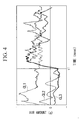
- FIGS. 4 and 5 show results of an investigation of changes in the air amount at an installation distance L (see FIG. 2) from the pivot shaft 12a of the throttle valve 12 when a throttle body 13 is used in the air intake passage 4 having a diameter of 22 mm and the engine 2 rotates 1500 times per minute.
- the horizontal axes represent elapsed time, and the vertical axes represent the air amount measured by the air flow meter 14.
- the link CL1 in FIG. 4 represents change in the air amount when the installation distance L is 22 mm.
- the line CL2 represents change in the air amount when the installation distance L is 44 mm, and the line CL3 represents change in the air amount when the insufficient flow is 66 mm.
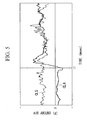
- the line CL4 of FIG. 5 represents change in the air amount when the installation distance L is 88 mm, and the line CL5 represents change in the air amount when the installation distance L is 110 mm.
- the time t1 is the timing for starting suction by opening the inlet valve 2b.
- the air flow meter 14 When the air flow meter 14 is provided at an installation distance L of 88 mm as shown by the line CL4 in FIG. 5, it can be seen that the air amount rises precipitously near time t1. Here too, the change in the air amount is greater than 0.00015 g. In contrast, at the installation distance L of 93 mm as shown by the line CL5, a large air amount is measured irrespective of the time, and the air amount near time t1 has neither pulsating flow or insufficient flow zones.
- the ideal installation position for the air flow meter 14 which can confirm the rise of suction in this embodiment is within the range of more than 44 mm and less than 88 mm from the position where the throttle valve 12 is attached. If the installation distance L is less than 44 mm, problems are caused by disruption of the air stream when the path is throttled by the throttle valve 12, and when the installation distance L exceeds 88 mm, the rise of suction cannot be determined due to disruption of the air stream.
- a more ideal installation distance L is between 44 mm and 66 mm, which is around the start of suction and has a greatly changing air amount.
- k is a predetermined coefficient having a value between 2 and 4.
- the diameter ⁇ is the average diameter of the air intake passage 4 in the region from the throttle valve 12 to the air flow meter 14.
- the diameter ⁇ indicates tendencies not only of the 22-mm diameter of the throttle body 13 but also similar tendencies of other diameters used in the engine 2.
- the installation distance L and the diameter ⁇ have a proportional relationship due to the fact that, although the air stream in the rear-stage of the throttle valve 12 is liable to become disrupted when the diameter ⁇ is large, the air stream thereafter continues to be stable for a long time.
- the installation distance L of the air flow meter 14 is twice to four times the diameter of the air intake passage 4.
- the air flow meter 14 measures the mass flow of air flowing along the air intake passage 4 at an installation distance L from the pivot shaft 12a of the throttle valve 12 on the downstream side thereof, and the control device 7 calculates an air amount based on this.
- the control device 7 determines that the engine 2 is not executing a suction stroke.
- the control device 7 determines the change in the calculated air amount and, if it satisfies conditions for an amount of change of a predetermined rise (e.g. an increase of 0.00015 g within a predetermined period of time), the control device 7 determines that suction has started from the start of that rise, and calculates the total air amount from that point as the suction amount.
- a predetermined rise e.g. an increase of 0.00015 g within a predetermined period of time
- the suction amount is used in calculating the injection amount of fuel to be injected from the injector 5.
- the injection amount is calculated by dividing the suction amount by a predetermined air-fuel ratio.
- the control device 7 outputs a signal corresponding to the calculated injection amount to the injector 5, which injects fuel into the air which makes suck the required amount of fuel.
- the air flow meter 14 which is installed at a distance of twice to four times the diameter of the air intake passage 4, can measure the decrease in the mass flow which accompanies this decrease in the air amount. Accordingly, when the calculated air amount falls below a predetermined value, the control device 7 determines that suction has ended and stops the injection of fuel. Since the fuel is injected into the sucked air from the start of suction until the end of suction, the air and the fuel can be efficiently mixed.
- the air flow meter 14 at a installation distance L downstream from the throttle valve 12, it becomes possible to determine the start and end of the suction stroke from changes in the air amount measured by the air flow meter 14.
- the suction timing can be measured without providing other sensors for measuring the rotation angles of the crank shaft 2d and the cam. Since the rise and fall of suction can be determined, the amount of air which is sucked during the suction stroke can be precisely measured.
- the air flow meter 14 can be used in combination with other sensors for measuring the rotation angles of the crank shaft 2d and the cam, making it possible to measure the amount of air sucked and the suction timing for each cylinder.
- the suction rise is used as a reference point for measuring the air amount used in calculating the fuel injection amount and as a reference point for the start of fuel injection, it can also be used as a reference point for the ignition timing in the engine 2. This is due to the fact that, while the ignition timing is determined beforehand as the angle of rotation of the crank shaft 2d, this angle of rotation can be determined from the time which elapses from the start of suction. Therefore, the mixed gas in the combustion chamber 2a should be ignited after a predetermined time has elapsed from the start of suction. Furthermore, the control device 7 may determine the number of rotations of the engine 2 by counting the generated cycles of the rise of suction, and adjust the time from the start of suction to ignition in accordance with the number of rotations of the engine 2.
- the present invention relates to a control system for internal combustion engine having a throttle valve inside an air intake passage, and includes a sensor which is installed downstream from the throttle valve and measures the amount of air sucked by the internal combustion engine, a control device which calculates the amount of fuel to be injected based on the air amount measured by the sensor; and an injector for fuel injection which injects fuel corresponding to the injection amount calculated by the control device.
- the distance between the installation position of the throttle valve and the installation position of the sensor is set at twice to four times the diameter of the air intake passage.
- the distance between the installation position of the throttle valve and the installation position of the sensor should preferably be between 44 mm and 66 mm.
- the start of suction can be determined from change in the air amount. Therefore, the amount of air sucked by the internal combustion engine can be accurately measured with a simple constitution, and the fuel injection amount can be determined by calculation based on the air amount measured. Since the timing of fuel injection takes the start of suction as a reference, fuel can be injected into air which is being sucked.
- the start of suction can be determined with high precision.
Landscapes
- Engineering & Computer Science (AREA)
- Chemical & Material Sciences (AREA)
- Combustion & Propulsion (AREA)
- Mechanical Engineering (AREA)
- General Engineering & Computer Science (AREA)
- Combined Controls Of Internal Combustion Engines (AREA)
- Electrical Control Of Air Or Fuel Supplied To Internal-Combustion Engine (AREA)
Abstract
An engine control system (1) measures an amount of air sucked by an engine (2) based on the output of an air flow meter (14) provided in an air intake passage (4), on the downstream side of a throttle valve (12), calculates an injection amount of fuel based on the air amount measured, and injects the fuel from an injector (5). The air flow meter (14) is installed at a position on the downstream side of the throttle valve (12), away from the valve (12) by a predetermined distance corresponding to twice to four times the diameter of the air intake passage (4).
Description
- The present invention relates to a control system that controls the injection amount and the like of fuel supplied to an internal combustion engine.
- Priority is claimed on Japanese Patent Application No. 2003-116814, filed April 22, 2003, the content of which is incorporated herein by reference.
- There are conventional methods for controlling combustion of an internal combustion engine in a vehicle and the like by controlling the spray amount of the fuel so as to match the amount of air sucked from the atmosphere, igniting a mixture of air and fuel in accordance with the angle of rotation of the crank shaft, and injecting it (e.g., see Japan Examined Patent Application, Second Publication No. H04-15388).
- The abovementioned document discloses a technique for controlling fuel injection. Specifically, an air flow sensor is used for controlling injection of fuel to a multi-cylinder engine, and is provided in an air intake passage between a throttle valve and an electromagnetic injection valve. A control circuit calculates a basic injection amount from the average flow of inlet air which is measured by the air flow sensor, and the fuel is injected based on this basic injection amount. While the engine cylinder which inlets air changes sequentially in each cycle, fluctuation in the air inlet flow arising at this time is treated as deviation from the average flow of inlet air, and a deviation signal which corresponds to this deviation is directly input to a voltage circuit of the electromagnetic injection valve. More fuel is injected when the deviation signal is large, and less fuel is injected when the deviation is small. The basic injection amount is calculated by compensation using an air inlet temperature sensor which measures the temperature of inlet air, and a cooling water temperature sensor which measures the temperature of cooling water in the engine.
- To increase the combustion efficiency and responsiveness, the amount of air actually sucked by the internal combustion engine should be measured in each case, and the optimal amount of fuel determined accordingly. However, when measuring the air flow near the throttle valve, disruption of the air stream caused by opening and closing the throttle valve makes it impossible to accurately measure the flow of air. On the other hand, since the air flow changes little at positions away from the throttle valve, it is difficult to measure changes in the air flow caused by the inlet stroke. In this case, the start and end of air suction must be confirmed by combined use of a sensor for measuring the angle of rotation of another crank shaft, a sensor for measuring the angle of rotation of the cam, and the like. This leads to problems in that, when the number of sensors required to control the injection of fuel increases, processing becomes accordingly complex and the load of the control circuit increases.
- The present invention has been realized in order to solve the problems mentioned above by providing a control system for internal combustion engine which has a simple constitution and can inject the required amount of fuel at an appropriate timing.
- The present invention provides a control system for internal combustion engine having a throttle valve in an air intake passage, and includes a sensor which is installed downstream from the throttle valve and measures an amount of air sucked by the internal combustion engine, a control device which calculates an injection amount of fuel based on the amount of air measured by the sensor, and an injector for fuel injection which injects fuel corresponding to the injection amount calculated by the control device. A distance between an installation position of the throttle valve and an installation position of the sensor is set at twice to four times a diameter of the air intake passage.
- According to this control system for internal combustion engine, the amount of air flowing in the air intake passage is measured at a predetermined distance downstream from the throttle valve. This distance is twice to four times the diameter of the air intake passage. Since this range is one in which air flows stably in the air intake passage, the sensor installed within this range can accurately measure increase in the flow of air in the air intake passage which accompanies suction. The result measured by the sensor is used by the control device in calculating the amount of fuel to be injected, and the fuel is injected by the injector in accordance with the injection amount calculated.
- In the control system for internal combustion engine of this invention, the distance between the installation position of the throttle valve and the installation position of the sensor should preferably be between 44 mm and 66 mm.
- According to this control system for internal combustion engine, the amount of air flowing in the air intake passage is measured by the sensor which is installed at a distance of between 44 mm and 66 mm downstream from the throttle valve. This enables large air amount changes to be measured during suction.
-
- FIG 1 is a schematic diagram of a control system for engine according to an embodiment of this invention.
- FIG. 2 is a diagram for explanation of an installation position of an air flow meter.
- FIG. 3 is a diagram of changes in an air amount which changes in accompaniment with the operation of an engine.
- FIG. 4 is a diagram of changes in the air amount for each installation position of an air flow meter.
- FIG. 5 is a diagram of changes in the air amount for each installation position of an air flow meter.
- A first embodiment of this invention will be explained in detail with reference to the drawings. FIG. 1 is a schematic diagram of a control system for internal combustion engine according to an embodiment of this invention. FIG. 2 is a diagram for explanation of an installation position of an air flow meter.
- An engine control system 1 of the embodiment shown in FIG. 1 sucks in air from an
air intake passage 4 which is connected to anintake manifold 3 of anengine 2, being an internal combustion engine, mixes this air with fuel which is injected from aninjector 5 fitted to theintake manifold 3, and causes it to combust inside acombustion chamber 2a of theengine 2. When discharging the combustion gas through anexhaust manifold 6 after combustion, acontrol device 7 controls the amount of fuel injected in accordance with the air flow measured by anair flow meter 14, being a sensor installed at a predetermined position in theair intake passage 4. - The
air intake passage 4 includes an air cleaner 11, and athrottle body 13 which is fitted with athrottle valve 12 for adjusting the amount of air, thethrottle body 13 being provided downstream from the air cleaner 11. Theair flow meter 14 is attached to thethrottle body 13, and measures the amount of air sucked into theengine 2 along theair intake passage 4 as mass flow. Theair flow meter 14 shown in FIG. 2 is positioned at a distance L downstream from apivot shaft 12a of thethrottle valve 12, and is able to measure the amount of air which is actually sucked into thecombustion chamber 2a of theengine 2 by using a measuring section 14a which is exposed in theair intake passage 4. Incidentally, the number of man-hours required for setting can be reduced by attaching theair flow meter 14 to thethrottle body 13. - One example of the
air flow meter 14 suitable for this embodiment is a sensor which includes the measuring section 14a made by disposition of a platinum thin-film on a silicon substrate, and applies a current such that the temperature of the platinum thin-film is kept constant. If the mass of air flowing around the platinum thin-film increases, the amount of heat dissipated from platinum thin-film through the air also increases, while the temperature of the platinum thin-film drops proportionally. At this time, theair flow meter 14 increases the current flowing through the platinum thin-film so as to keep the temperature constant. On the other hand, when the amount of conduction in the air decreases, since the heat dissipation decreases and the temperature of the platinum thin-film increases, theair flow meter 14 reduces the current flowing through the platinum thin-film accordingly. Since the current value increases/decreases in proportion to the increase/decrease in the mass of air flowing around the platinum thin-film, the amount of air can be measured by monitoring this current value. This type ofair flow meter 14 can reduce the heat capacity more than when using a platinum wire, and consequently has high responsiveness and high measuring precision. - The
injector 5 shown in FIG. 1 injects fuel into the air flowing through theintake manifold 3 by opening and closing the electromagnetic injection valve, whereby fuel is scooped from afuel pump 16 inside afuel tank 15 and regulated by a regulator before being supplied. - Mixed gas is supplied to the
combustion chamber 2a and discharged therefrom after combustion by aninlet valve 2b and anoutlet valve 2c, which are driven by an unillustrated bubble timing mechanism. - The mixed gas is ignited by an
ignition plug 8. The ignition plug 8 discharges using high energy stored in anignition circuit 9. - The
control device 7 which implements control in this engine control system 1 is also termed an electronic control unit (ECU). Thecontrol device 7 includes a central processing unit (CPU) or a read only memory (ROM) and the like, and is driven by power supplied from abattery 10. Thecontrol device 7 receives the output current of theair flow meter 14 as input data, executes predetermined processing thereto, determines the amount of fuel supplied to theinjector 5 from thefuel pump 15, the injection amount of theinjector 5 and an injection timing, and a timing of starting recharging to theignition circuit 9, and an ignition timing, and outputs command signals to the respective units. - Here, the
control device 7 includes an air amount calculation device which calculates the amount of air by multiplying the output current of theair flow meter 14 by a predetermined coefficient, a determination device which determines the rise of suction and the fall of suction from changes in the air amount, an integration device which integrates the air amount from the start of suction, and an injection amount control device which controls theinjector 5 and the like. Thecontrol device 7 executes control to discharge theignition plug 8 at a predetermined timing and combust a mixed gas of air and fuel, and for that purpose includes an ignition control device which calculates and controls the charge time of theignition circuit 9 in accordance with the intake air amount and the fuel amount. Thecontrol device 7 may have a configuration which does not control ignition. In this case, another control device is provided and functions as an ignition control device. - The data processed by the
control device 7 and the processing itself will be explained using FIG. 1 and FIG. 3. FIG. 3 is a diagram of changes in the air amount which changes in accompaniment with operation of an engine, the horizontal axis representing elapsed time and the vertical axis representing the intake air amount. - In FIG. 3, the air amount which fluctuates as time elapses is a value calculated by multiplying the current output from the
air flow meter 14 by a predetermined coefficient. The air amount thus calculateed is treated as front-flow when it is greater than a predetermined threshold (reference value), and as back-flow when it is below this threshold. Here, 'front-flow' is air which flows in the direction of being sucked into theengine 2. 'Back-flow' is air which flows in the opposite direction, i.e. the direction of thethrottle valve 12, and is caused when theinlet valve 2b of theengine 2 is closed and the trapped air flows in the opposite direction. A state where front-flow and back-flow are generated alternately is termed 'pulsating flow'. - There are times when the
inlet valve 2b of theengine 2 opens while thethrottle valve 12 is slightly open, generating negative pressure inside theair intake passage 4. This negative pressure remains even after theinlet valve 2b is closed, and may cause a small flow of air entering through thethrottle valve 12. The flow of air generated under such conditions is termed 'insufficient flow'. - The region where the air amount is increasing beyond the range of pulsating flow and insufficient flow is the region where air is being sucked into the
engine 2, and corresponds to the suction stroke of theengine 2. The start of suction (rise of suction) is deemed to be the point at which the air amount exceeds the size of the pulsating flow and the insufficient flow and rises from zero. Since the start of suction is determined by the timing at which theinlet valve 2b opens (a predetermined angle of thecrank shaft 2d) irrespective of the number of rotations of theengine 2, it is possible to control the timing of fuel injection and the ignition timing by taking this point as a reference. - The end of suction (fall of suction) is the point where the air amount, which has peaked and is decreasing, drops to zero.
- The attachment position of the
air flow meter 14 and its relationship with the pros and cons of measuring the rise of suction will be explained with reference to FIG. 4 and FIG. 5. - FIGS. 4 and 5 show results of an investigation of changes in the air amount at an installation distance L (see FIG. 2) from the
pivot shaft 12a of thethrottle valve 12 when athrottle body 13 is used in theair intake passage 4 having a diameter of 22 mm and theengine 2 rotates 1500 times per minute. The horizontal axes represent elapsed time, and the vertical axes represent the air amount measured by theair flow meter 14. The link CL1 in FIG. 4 represents change in the air amount when the installation distance L is 22 mm. The line CL2 represents change in the air amount when the installation distance L is 44 mm, and the line CL3 represents change in the air amount when the insufficient flow is 66 mm. The line CL4 of FIG. 5 represents change in the air amount when the installation distance L is 88 mm, and the line CL5 represents change in the air amount when the installation distance L is 110 mm. The time t1 is the timing for starting suction by opening theinlet valve 2b. - As shown by the line CL1 in FIG. 4, when the
air flow meter 14 is provided at an installation distance L of 22 mm, a large air amount is measured from the beginning and the rise of suction cannot be confirmed at time t1. At the installation distance L of 44 mm shown by the line CL2, a small air amount is firstly measured as a pulsating flow and an insufficient flow, rises precipitously near the time t1, and thereafter a large air amount is maintained. At the installation distance L of 66 mm shown by the line CL3, the air amount rises precipitously near time t1 and thereafter pulsates while gently decreasing. While the change in the air amount at the installation distances L of 44 mm and 66 mm also differs according to the capacity of theengine 2, it is greater than 0.00015 g. This is a sufficient change in the air amount to identify a pulsating flow, an insufficient flow, and the rise of suction. - When the
air flow meter 14 is provided at an installation distance L of 88 mm as shown by the line CL4 in FIG. 5, it can be seen that the air amount rises precipitously near time t1. Here too, the change in the air amount is greater than 0.00015 g. In contrast, at the installation distance L of 93 mm as shown by the line CL5, a large air amount is measured irrespective of the time, and the air amount near time t1 has neither pulsating flow or insufficient flow zones. - To identify the start of suction from the results measured by the
air flow meter 14, a large change in the air amount (e.g. more than 0.0001 g) is needed within a short period of time. Therefore, the ideal installation position for theair flow meter 14 which can confirm the rise of suction in this embodiment is within the range of more than 44 mm and less than 88 mm from the position where thethrottle valve 12 is attached. If the installation distance L is less than 44 mm, problems are caused by disruption of the air stream when the path is throttled by thethrottle valve 12, and when the installation distance L exceeds 88 mm, the rise of suction cannot be determined due to disruption of the air stream. A more ideal installation distance L is between 44 mm and 66 mm, which is around the start of suction and has a greatly changing air amount. - The ideal installation distance L of the
air flow meter 14 can be expressed using the diameter ϕ of theair intake passage 4 where theair flow meter 14 is attached as L = k × ϕ. Here, k is a predetermined coefficient having a value between 2 and 4. The diameter ϕ is the average diameter of theair intake passage 4 in the region from thethrottle valve 12 to theair flow meter 14. The diameter ϕ indicates tendencies not only of the 22-mm diameter of thethrottle body 13 but also similar tendencies of other diameters used in theengine 2. The installation distance L and the diameter ϕ have a proportional relationship due to the fact that, although the air stream in the rear-stage of thethrottle valve 12 is liable to become disrupted when the diameter ϕ is large, the air stream thereafter continues to be stable for a long time. - Subsequently, an operation executed by the
control device 7 as interrupt processing in each fixed cycle after theengine 2 starts operating will be explained. Here, the installation distance L of theair flow meter 14 is twice to four times the diameter of theair intake passage 4. - Firstly, the
air flow meter 14 measures the mass flow of air flowing along theair intake passage 4 at an installation distance L from thepivot shaft 12a of thethrottle valve 12 on the downstream side thereof, and thecontrol device 7 calculates an air amount based on this. When theinlet valve 2b of theengine 2 is closed, the air amount flowing is small, and so thecontrol device 7 determines that theengine 2 is not executing a suction stroke. - On the other hand, when the suction stroke of the
engine 2 starts and theinlet valve 2b opens, the air in theair intake passage 4 is sucked into thecombustion chamber 2a and the amount of air flowing theair intake passage 4 increases precipitously. Theair flow meter 14 measures the increasing mass flow of the air and outputs a signal to thecontrol device 7. Thecontrol device 7 determines the change in the calculated air amount and, if it satisfies conditions for an amount of change of a predetermined rise (e.g. an increase of 0.00015 g within a predetermined period of time), thecontrol device 7 determines that suction has started from the start of that rise, and calculates the total air amount from that point as the suction amount. The suction amount is used in calculating the injection amount of fuel to be injected from theinjector 5. The injection amount is calculated by dividing the suction amount by a predetermined air-fuel ratio. Thecontrol device 7 outputs a signal corresponding to the calculated injection amount to theinjector 5, which injects fuel into the air which makes suck the required amount of fuel. - As the suction stroke ends and the
inlet valve 2b starts to close, the amount of air flowing in theair intake passage 4 decreases. Theair flow meter 14, which is installed at a distance of twice to four times the diameter of theair intake passage 4, can measure the decrease in the mass flow which accompanies this decrease in the air amount. Accordingly, when the calculated air amount falls below a predetermined value, thecontrol device 7 determines that suction has ended and stops the injection of fuel. Since the fuel is injected into the sucked air from the start of suction until the end of suction, the air and the fuel can be efficiently mixed. - Thus, by providing the
air flow meter 14 at a installation distance L downstream from thethrottle valve 12, it becomes possible to determine the start and end of the suction stroke from changes in the air amount measured by theair flow meter 14. In the case of a single-cylinder engine 2, the suction timing can be measured without providing other sensors for measuring the rotation angles of thecrank shaft 2d and the cam. Since the rise and fall of suction can be determined, the amount of air which is sucked during the suction stroke can be precisely measured. In the case of amulti-cylinder engine 2, theair flow meter 14 can be used in combination with other sensors for measuring the rotation angles of thecrank shaft 2d and the cam, making it possible to measure the amount of air sucked and the suction timing for each cylinder. - While the suction rise is used as a reference point for measuring the air amount used in calculating the fuel injection amount and as a reference point for the start of fuel injection, it can also be used as a reference point for the ignition timing in the
engine 2. This is due to the fact that, while the ignition timing is determined beforehand as the angle of rotation of thecrank shaft 2d, this angle of rotation can be determined from the time which elapses from the start of suction. Therefore, the mixed gas in thecombustion chamber 2a should be ignited after a predetermined time has elapsed from the start of suction. Furthermore, thecontrol device 7 may determine the number of rotations of theengine 2 by counting the generated cycles of the rise of suction, and adjust the time from the start of suction to ignition in accordance with the number of rotations of theengine 2. - The present invention relates to a control system for internal combustion engine having a throttle valve inside an air intake passage, and includes a sensor which is installed downstream from the throttle valve and measures the amount of air sucked by the internal combustion engine, a control device which calculates the amount of fuel to be injected based on the air amount measured by the sensor; and an injector for fuel injection which injects fuel corresponding to the injection amount calculated by the control device. The distance between the installation position of the throttle valve and the installation position of the sensor is set at twice to four times the diameter of the air intake passage.
- In the control system for internal combustion engine of this invention, the distance between the installation position of the throttle valve and the installation position of the sensor should preferably be between 44 mm and 66 mm.
- According to the control system for internal combustion engine of this invention, the start of suction can be determined from change in the air amount. Therefore, the amount of air sucked by the internal combustion engine can be accurately measured with a simple constitution, and the fuel injection amount can be determined by calculation based on the air amount measured. Since the timing of fuel injection takes the start of suction as a reference, fuel can be injected into air which is being sucked.
- Furthermore, according to the control system for internal combustion engine of this invention, since large air amount change can be measured at the start of suction, the start of suction can be determined with high precision.
Claims (2)
- A control system for internal combustion engine having a throttle valve in an air intake passage, comprising:a sensor which is installed downstream from the throttle valve and measures an amount of air sucked by the internal combustion engine;a control device which calculates an injection amount of fuel based on the amount of air measured by the sensor; andan injector for fuel injection which injects fuel corresponding to the injection amount calculated by the control device,wherein a distance between an installation position of the throttle valve and an installation position of the sensor is twice to four times a diameter of the air intake passage.
- A control system for internal combustion engine according to claim 1, wherein the distance between the installation position of the throttle valve and the installation position of the sensor is between 44 mm and 66 mm.
Applications Claiming Priority (2)
| Application Number | Priority Date | Filing Date | Title |
|---|---|---|---|
| JP2003116814A JP3926763B2 (en) | 2003-04-22 | 2003-04-22 | Internal combustion engine control system |
| PCT/JP2004/005568 WO2004094799A1 (en) | 2003-04-22 | 2004-04-19 | Control system for internal combustion engine |
Publications (1)
| Publication Number | Publication Date |
|---|---|
| EP1637716A1 true EP1637716A1 (en) | 2006-03-22 |
Family
ID=33308002
Family Applications (1)
| Application Number | Title | Priority Date | Filing Date |
|---|---|---|---|
| EP04728263A Withdrawn EP1637716A1 (en) | 2003-04-22 | 2004-04-19 | Control system for internal combustion engine |
Country Status (5)
| Country | Link |
|---|---|
| US (1) | US7188612B2 (en) |
| EP (1) | EP1637716A1 (en) |
| JP (1) | JP3926763B2 (en) |
| CN (1) | CN100406700C (en) |
| WO (1) | WO2004094799A1 (en) |
Families Citing this family (5)
| Publication number | Priority date | Publication date | Assignee | Title |
|---|---|---|---|---|
| JP2004324425A (en) * | 2003-04-21 | 2004-11-18 | Keihin Corp | Control device for internal combustion engine |
| US7520272B2 (en) * | 2006-01-24 | 2009-04-21 | General Electric Company | Fuel injector |
| US7359795B2 (en) * | 2006-08-28 | 2008-04-15 | Ard Technology, Llc | Calibration method for air intake tracts for internal combustion engines |
| CN103216346B (en) * | 2008-03-17 | 2016-02-10 | 胡斯华纳有限公司 | Throttle position sensor, fuel supply unit and control module thereof, ignition system |
| PL2290217T3 (en) * | 2008-03-17 | 2016-12-30 | Fuel supply unit |
Family Cites Families (6)
| Publication number | Priority date | Publication date | Assignee | Title |
|---|---|---|---|---|
| JPS5827839A (en) | 1981-08-10 | 1983-02-18 | Mitsubishi Electric Corp | Fuel supply system for internal combustion engines |
| JPS59188037A (en) * | 1983-03-08 | 1984-10-25 | Mazda Motor Corp | Fuel injection controller of engine |
| JPH0415388A (en) | 1990-05-01 | 1992-01-20 | Mirai Ind Co Ltd | Connecting structure of corrugated pipe and connecting fitting |
| DE4115032A1 (en) | 1991-05-08 | 1992-11-12 | Bosch Gmbh Robert | ELECTRONIC SYSTEM IN A MOTOR VEHICLE FOR DETECTING A BAD ROUTE |
| JPH0572074A (en) | 1991-09-12 | 1993-03-23 | Fujitsu Ten Ltd | Method for measuring pressure of intake pipe in internal combustion engine |
| JP4442740B2 (en) * | 2000-10-17 | 2010-03-31 | ヤマハ発動機株式会社 | Ship propulsion unit intake system |
-
2003
- 2003-04-22 JP JP2003116814A patent/JP3926763B2/en not_active Expired - Lifetime
-
2004
- 2004-04-19 WO PCT/JP2004/005568 patent/WO2004094799A1/en not_active Ceased
- 2004-04-19 EP EP04728263A patent/EP1637716A1/en not_active Withdrawn
- 2004-04-19 CN CNB200480010521XA patent/CN100406700C/en not_active Expired - Fee Related
- 2004-04-19 US US10/552,746 patent/US7188612B2/en not_active Expired - Fee Related
Non-Patent Citations (1)
| Title |
|---|
| See references of WO2004094799A1 * |
Also Published As
| Publication number | Publication date |
|---|---|
| WO2004094799A1 (en) | 2004-11-04 |
| US7188612B2 (en) | 2007-03-13 |
| JP3926763B2 (en) | 2007-06-06 |
| JP2004324450A (en) | 2004-11-18 |
| US20060180126A1 (en) | 2006-08-17 |
| CN100406700C (en) | 2008-07-30 |
| CN1777744A (en) | 2006-05-24 |
Similar Documents
| Publication | Publication Date | Title |
|---|---|---|
| US7188612B2 (en) | Control system for internal combustion engine | |
| CN100379962C (en) | Air intake for internal combustion engines | |
| US11181058B2 (en) | Method for measuring exhaust gas recirculation flow in an engine system, controlling emissions in an engine system, and an engine system | |
| US7395700B2 (en) | Intake device for internal combustion engine and method of measuring intake air amount | |
| US7231909B2 (en) | Air intake apparatus and control apparatus for an internal combustion engine | |
| JP3961446B2 (en) | Control device for internal combustion engine | |
| CN100370125C (en) | Control device for internal combustion engine | |
| JPS5861411A (en) | Measuring device for flow rate of gas | |
| JP2004324425A (en) | Control device for internal combustion engine | |
| JP2005106000A (en) | Control device for internal combustion engine |
Legal Events
| Date | Code | Title | Description |
|---|---|---|---|
| PUAI | Public reference made under article 153(3) epc to a published international application that has entered the european phase |
Free format text: ORIGINAL CODE: 0009012 |
|
| 17P | Request for examination filed |
Effective date: 20051007 |
|
| AK | Designated contracting states |
Kind code of ref document: A1 Designated state(s): DE FR GB |
|
| DAX | Request for extension of the european patent (deleted) | ||
| RBV | Designated contracting states (corrected) |
Designated state(s): DE FR GB |
|
| STAA | Information on the status of an ep patent application or granted ep patent |
Free format text: STATUS: THE APPLICATION IS DEEMED TO BE WITHDRAWN |
|
| 18D | Application deemed to be withdrawn |
Effective date: 20091103 |