EP1635742B1 - Hip prosthesis - Google Patents
Hip prosthesis Download PDFInfo
- Publication number
- EP1635742B1 EP1635742B1 EP03817192A EP03817192A EP1635742B1 EP 1635742 B1 EP1635742 B1 EP 1635742B1 EP 03817192 A EP03817192 A EP 03817192A EP 03817192 A EP03817192 A EP 03817192A EP 1635742 B1 EP1635742 B1 EP 1635742B1
- Authority
- EP
- European Patent Office
- Prior art keywords
- truncated cones
- half truncated
- cavity
- neck
- stem
- Prior art date
- Legal status (The legal status is an assumption and is not a legal conclusion. Google has not performed a legal analysis and makes no representation as to the accuracy of the status listed.)
- Expired - Lifetime
Links
- 210000001624 hip Anatomy 0.000 claims abstract description 13
- 230000000295 complement effect Effects 0.000 claims abstract description 5
- 239000007787 solid Substances 0.000 claims abstract description 5
- 210000000588 acetabulum Anatomy 0.000 claims abstract description 3
- 210000000689 upper leg Anatomy 0.000 claims abstract description 3
- 206010061218 Inflammation Diseases 0.000 description 1
- 208000035965 Postoperative Complications Diseases 0.000 description 1
- 230000002411 adverse Effects 0.000 description 1
- 230000002950 deficient Effects 0.000 description 1
- 230000007850 degeneration Effects 0.000 description 1
- 210000004394 hip joint Anatomy 0.000 description 1
- 230000004054 inflammatory process Effects 0.000 description 1
- 238000012829 orthopaedic surgery Methods 0.000 description 1
- 210000001519 tissue Anatomy 0.000 description 1
Images
Classifications
-
- A—HUMAN NECESSITIES
- A61—MEDICAL OR VETERINARY SCIENCE; HYGIENE
- A61F—FILTERS IMPLANTABLE INTO BLOOD VESSELS; PROSTHESES; DEVICES PROVIDING PATENCY TO, OR PREVENTING COLLAPSING OF, TUBULAR STRUCTURES OF THE BODY, e.g. STENTS; ORTHOPAEDIC, NURSING OR CONTRACEPTIVE DEVICES; FOMENTATION; TREATMENT OR PROTECTION OF EYES OR EARS; BANDAGES, DRESSINGS OR ABSORBENT PADS; FIRST-AID KITS
- A61F2/00—Filters implantable into blood vessels; Prostheses, i.e. artificial substitutes or replacements for parts of the body; Appliances for connecting them with the body; Devices providing patency to, or preventing collapsing of, tubular structures of the body, e.g. stents
- A61F2/02—Prostheses implantable into the body
- A61F2/30—Joints
- A61F2/32—Joints for the hip
- A61F2/36—Femoral heads ; Femoral endoprostheses
- A61F2/3609—Femoral heads or necks; Connections of endoprosthetic heads or necks to endoprosthetic femoral shafts
-
- A—HUMAN NECESSITIES
- A61—MEDICAL OR VETERINARY SCIENCE; HYGIENE
- A61F—FILTERS IMPLANTABLE INTO BLOOD VESSELS; PROSTHESES; DEVICES PROVIDING PATENCY TO, OR PREVENTING COLLAPSING OF, TUBULAR STRUCTURES OF THE BODY, e.g. STENTS; ORTHOPAEDIC, NURSING OR CONTRACEPTIVE DEVICES; FOMENTATION; TREATMENT OR PROTECTION OF EYES OR EARS; BANDAGES, DRESSINGS OR ABSORBENT PADS; FIRST-AID KITS
- A61F2/00—Filters implantable into blood vessels; Prostheses, i.e. artificial substitutes or replacements for parts of the body; Appliances for connecting them with the body; Devices providing patency to, or preventing collapsing of, tubular structures of the body, e.g. stents
- A61F2/02—Prostheses implantable into the body
- A61F2/30—Joints
- A61F2/32—Joints for the hip
- A61F2/36—Femoral heads ; Femoral endoprostheses
- A61F2/3662—Femoral shafts
- A61F2/367—Proximal or metaphyseal parts of shafts
-
- A—HUMAN NECESSITIES
- A61—MEDICAL OR VETERINARY SCIENCE; HYGIENE
- A61F—FILTERS IMPLANTABLE INTO BLOOD VESSELS; PROSTHESES; DEVICES PROVIDING PATENCY TO, OR PREVENTING COLLAPSING OF, TUBULAR STRUCTURES OF THE BODY, e.g. STENTS; ORTHOPAEDIC, NURSING OR CONTRACEPTIVE DEVICES; FOMENTATION; TREATMENT OR PROTECTION OF EYES OR EARS; BANDAGES, DRESSINGS OR ABSORBENT PADS; FIRST-AID KITS
- A61F2/00—Filters implantable into blood vessels; Prostheses, i.e. artificial substitutes or replacements for parts of the body; Appliances for connecting them with the body; Devices providing patency to, or preventing collapsing of, tubular structures of the body, e.g. stents
- A61F2/02—Prostheses implantable into the body
- A61F2/30—Joints
- A61F2002/30001—Additional features of subject-matter classified in A61F2/28, A61F2/30 and subgroups thereof
- A61F2002/30108—Shapes
- A61F2002/3011—Cross-sections or two-dimensional shapes
- A61F2002/30112—Rounded shapes, e.g. with rounded corners
- A61F2002/3013—Rounded shapes, e.g. with rounded corners figure-"8"- or hourglass-shaped
-
- A—HUMAN NECESSITIES
- A61—MEDICAL OR VETERINARY SCIENCE; HYGIENE
- A61F—FILTERS IMPLANTABLE INTO BLOOD VESSELS; PROSTHESES; DEVICES PROVIDING PATENCY TO, OR PREVENTING COLLAPSING OF, TUBULAR STRUCTURES OF THE BODY, e.g. STENTS; ORTHOPAEDIC, NURSING OR CONTRACEPTIVE DEVICES; FOMENTATION; TREATMENT OR PROTECTION OF EYES OR EARS; BANDAGES, DRESSINGS OR ABSORBENT PADS; FIRST-AID KITS
- A61F2/00—Filters implantable into blood vessels; Prostheses, i.e. artificial substitutes or replacements for parts of the body; Appliances for connecting them with the body; Devices providing patency to, or preventing collapsing of, tubular structures of the body, e.g. stents
- A61F2/02—Prostheses implantable into the body
- A61F2/30—Joints
- A61F2002/30001—Additional features of subject-matter classified in A61F2/28, A61F2/30 and subgroups thereof
- A61F2002/30316—The prosthesis having different structural features at different locations within the same prosthesis; Connections between prosthetic parts; Special structural features of bone or joint prostheses not otherwise provided for
- A61F2002/30329—Connections or couplings between prosthetic parts, e.g. between modular parts; Connecting elements
- A61F2002/30331—Connections or couplings between prosthetic parts, e.g. between modular parts; Connecting elements made by longitudinally pushing a protrusion into a complementarily-shaped recess, e.g. held by friction fit
- A61F2002/30332—Conically- or frustoconically-shaped protrusion and recess
- A61F2002/30334—Cone of elliptical or oval basis
-
- A—HUMAN NECESSITIES
- A61—MEDICAL OR VETERINARY SCIENCE; HYGIENE
- A61F—FILTERS IMPLANTABLE INTO BLOOD VESSELS; PROSTHESES; DEVICES PROVIDING PATENCY TO, OR PREVENTING COLLAPSING OF, TUBULAR STRUCTURES OF THE BODY, e.g. STENTS; ORTHOPAEDIC, NURSING OR CONTRACEPTIVE DEVICES; FOMENTATION; TREATMENT OR PROTECTION OF EYES OR EARS; BANDAGES, DRESSINGS OR ABSORBENT PADS; FIRST-AID KITS
- A61F2/00—Filters implantable into blood vessels; Prostheses, i.e. artificial substitutes or replacements for parts of the body; Appliances for connecting them with the body; Devices providing patency to, or preventing collapsing of, tubular structures of the body, e.g. stents
- A61F2/02—Prostheses implantable into the body
- A61F2/30—Joints
- A61F2002/30001—Additional features of subject-matter classified in A61F2/28, A61F2/30 and subgroups thereof
- A61F2002/30316—The prosthesis having different structural features at different locations within the same prosthesis; Connections between prosthetic parts; Special structural features of bone or joint prostheses not otherwise provided for
- A61F2002/30329—Connections or couplings between prosthetic parts, e.g. between modular parts; Connecting elements
- A61F2002/30331—Connections or couplings between prosthetic parts, e.g. between modular parts; Connecting elements made by longitudinally pushing a protrusion into a complementarily-shaped recess, e.g. held by friction fit
- A61F2002/30362—Connections or couplings between prosthetic parts, e.g. between modular parts; Connecting elements made by longitudinally pushing a protrusion into a complementarily-shaped recess, e.g. held by friction fit with possibility of relative movement between the protrusion and the recess
- A61F2002/30364—Rotation about the common longitudinal axis
- A61F2002/30367—Rotation about the common longitudinal axis with additional means for preventing said rotation
-
- A—HUMAN NECESSITIES
- A61—MEDICAL OR VETERINARY SCIENCE; HYGIENE
- A61F—FILTERS IMPLANTABLE INTO BLOOD VESSELS; PROSTHESES; DEVICES PROVIDING PATENCY TO, OR PREVENTING COLLAPSING OF, TUBULAR STRUCTURES OF THE BODY, e.g. STENTS; ORTHOPAEDIC, NURSING OR CONTRACEPTIVE DEVICES; FOMENTATION; TREATMENT OR PROTECTION OF EYES OR EARS; BANDAGES, DRESSINGS OR ABSORBENT PADS; FIRST-AID KITS
- A61F2/00—Filters implantable into blood vessels; Prostheses, i.e. artificial substitutes or replacements for parts of the body; Appliances for connecting them with the body; Devices providing patency to, or preventing collapsing of, tubular structures of the body, e.g. stents
- A61F2/02—Prostheses implantable into the body
- A61F2/30—Joints
- A61F2/32—Joints for the hip
- A61F2/36—Femoral heads ; Femoral endoprostheses
- A61F2/3609—Femoral heads or necks; Connections of endoprosthetic heads or necks to endoprosthetic femoral shafts
- A61F2002/3625—Necks
-
- A—HUMAN NECESSITIES
- A61—MEDICAL OR VETERINARY SCIENCE; HYGIENE
- A61F—FILTERS IMPLANTABLE INTO BLOOD VESSELS; PROSTHESES; DEVICES PROVIDING PATENCY TO, OR PREVENTING COLLAPSING OF, TUBULAR STRUCTURES OF THE BODY, e.g. STENTS; ORTHOPAEDIC, NURSING OR CONTRACEPTIVE DEVICES; FOMENTATION; TREATMENT OR PROTECTION OF EYES OR EARS; BANDAGES, DRESSINGS OR ABSORBENT PADS; FIRST-AID KITS
- A61F2/00—Filters implantable into blood vessels; Prostheses, i.e. artificial substitutes or replacements for parts of the body; Appliances for connecting them with the body; Devices providing patency to, or preventing collapsing of, tubular structures of the body, e.g. stents
- A61F2/02—Prostheses implantable into the body
- A61F2/30—Joints
- A61F2/32—Joints for the hip
- A61F2/36—Femoral heads ; Femoral endoprostheses
- A61F2/3609—Femoral heads or necks; Connections of endoprosthetic heads or necks to endoprosthetic femoral shafts
- A61F2002/365—Connections of heads to necks
-
- A—HUMAN NECESSITIES
- A61—MEDICAL OR VETERINARY SCIENCE; HYGIENE
- A61F—FILTERS IMPLANTABLE INTO BLOOD VESSELS; PROSTHESES; DEVICES PROVIDING PATENCY TO, OR PREVENTING COLLAPSING OF, TUBULAR STRUCTURES OF THE BODY, e.g. STENTS; ORTHOPAEDIC, NURSING OR CONTRACEPTIVE DEVICES; FOMENTATION; TREATMENT OR PROTECTION OF EYES OR EARS; BANDAGES, DRESSINGS OR ABSORBENT PADS; FIRST-AID KITS
- A61F2/00—Filters implantable into blood vessels; Prostheses, i.e. artificial substitutes or replacements for parts of the body; Appliances for connecting them with the body; Devices providing patency to, or preventing collapsing of, tubular structures of the body, e.g. stents
- A61F2/02—Prostheses implantable into the body
- A61F2/30—Joints
- A61F2/32—Joints for the hip
- A61F2/36—Femoral heads ; Femoral endoprostheses
- A61F2/3609—Femoral heads or necks; Connections of endoprosthetic heads or necks to endoprosthetic femoral shafts
- A61F2002/3652—Connections of necks to shafts
-
- A—HUMAN NECESSITIES
- A61—MEDICAL OR VETERINARY SCIENCE; HYGIENE
- A61F—FILTERS IMPLANTABLE INTO BLOOD VESSELS; PROSTHESES; DEVICES PROVIDING PATENCY TO, OR PREVENTING COLLAPSING OF, TUBULAR STRUCTURES OF THE BODY, e.g. STENTS; ORTHOPAEDIC, NURSING OR CONTRACEPTIVE DEVICES; FOMENTATION; TREATMENT OR PROTECTION OF EYES OR EARS; BANDAGES, DRESSINGS OR ABSORBENT PADS; FIRST-AID KITS
- A61F2220/00—Fixations or connections for prostheses classified in groups A61F2/00 - A61F2/26 or A61F2/82 or A61F9/00 or A61F11/00 or subgroups thereof
- A61F2220/0025—Connections or couplings between prosthetic parts, e.g. between modular parts; Connecting elements
- A61F2220/0033—Connections or couplings between prosthetic parts, e.g. between modular parts; Connecting elements made by longitudinally pushing a protrusion into a complementary-shaped recess, e.g. held by friction fit
-
- A—HUMAN NECESSITIES
- A61—MEDICAL OR VETERINARY SCIENCE; HYGIENE
- A61F—FILTERS IMPLANTABLE INTO BLOOD VESSELS; PROSTHESES; DEVICES PROVIDING PATENCY TO, OR PREVENTING COLLAPSING OF, TUBULAR STRUCTURES OF THE BODY, e.g. STENTS; ORTHOPAEDIC, NURSING OR CONTRACEPTIVE DEVICES; FOMENTATION; TREATMENT OR PROTECTION OF EYES OR EARS; BANDAGES, DRESSINGS OR ABSORBENT PADS; FIRST-AID KITS
- A61F2230/00—Geometry of prostheses classified in groups A61F2/00 - A61F2/26 or A61F2/82 or A61F9/00 or A61F11/00 or subgroups thereof
- A61F2230/0002—Two-dimensional shapes, e.g. cross-sections
- A61F2230/0004—Rounded shapes, e.g. with rounded corners
- A61F2230/001—Figure-8-shaped, e.g. hourglass-shaped
Definitions
- the present invention relates to the field of prostheses used in orthopaedic surgery. More specifically, the invention relates to a hip prosthesis structure.
- this structure essentially comprises a stem which is to be inserted into the upper portion of the femur and which has a cavity in its top for the stable housing of the free end of a shaped bar, called the "neck", on the other end of which is fitted a spherical head which is joined to the acetabulum of the hip of the patient on whom the operation is performed.
- EP-A-677281 discloses a hip-prosthesis with a femur-stem with a cavity on its top for receiving one end of a bar with a spherical head.
- the stability of the joint between the neck of the prosthesis and the said cavity of the stem in which it is inserted is of fundamental importance to the success of the operation: this is because relative movements between the two parts after the fitting of the prosthesis can generate debris which may lead to inflammation, degeneration and fracture of the tissues of the various parts of the hip region, with unforeseeable consequences which may seriously compromise the success of the operation.
- the free end of the said neck and the said cavity are at present constructed with complementary profiles and, in order to improve the reliability of the joint, they are made in the form of a solid consisting of two bases, essentially parallel to each other, linked by surfaces inclined with respect to the said bases and converging towards the stem.
- the inventor of the hip prosthesis structure described herein considers that the risks of post-operative complications can be reduced considerably by making the said neck and the said cavity in such a way as to provide certainty of the absolute correctness of their joining in the direction described previously in which the maximum stresses occur, while deliberately forgoing any attempt to achieve a simultaneous forced joint between the parts in the direction perpendicular to the said direction, in which negligible risks are incurred.
- the inventor has devised a hip prosthesis structure in which the said free end of the neck is shaped in the form of two half truncated cones positioned so that they are mirror images of each other and delimited transversely by two bases which are essentially flat and parallel, the two half truncated cones being linked to each other by two surfaces which form two slight recesses which are inside the two planes tangent to the half truncated cones on opposite sides of the plane containing their axes.
- the shape of the said cavity is complementary to the solid formed by the two half truncated cones and by the two planes tangent to them.
- the object of the present invention is a hip prosthesis structure as described in the attached Claim 1.
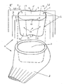
- FIG. 1 shows an exploded and partially transparent view of the free end of a neck (the other end 4d to which a spherical head is fitted is not illustrated, but simply indicated in broken lines) and of a stem with a cavity made according to the invention.
- the figure shows how, in a hip prosthesis structure 1 according to the invention, the terminal part of the said neck 4 has, as stated above, the shape of two half truncated cones 5 and 6, positioned so that they are mirror images of each other and delimited transversely by two bases 7 and 7' which are essentially flat and parallel.
- the said two half truncated cones 5 and 6 are linked to each other by two surfaces 8 and 9 which form two slight recesses 10 and 11 (emphasized for clarity in the drawing) which are inside the planes â and â ' tangent to the half truncated cones 5 and 6 on opposite sides of the plane ⁇ containing their axes L-L and M-M.
- the shape of the said cavity 3 of the stem 2 is complementary to the solid 12 formed by the two half truncated cones 5 and 6 and by the said two planes â and â' tangent to them.
Landscapes
- Health & Medical Sciences (AREA)
- Orthopedic Medicine & Surgery (AREA)
- Cardiology (AREA)
- Oral & Maxillofacial Surgery (AREA)
- Transplantation (AREA)
- Engineering & Computer Science (AREA)
- Biomedical Technology (AREA)
- Heart & Thoracic Surgery (AREA)
- Vascular Medicine (AREA)
- Life Sciences & Earth Sciences (AREA)
- Animal Behavior & Ethology (AREA)
- General Health & Medical Sciences (AREA)
- Public Health (AREA)
- Veterinary Medicine (AREA)
- Prostheses (AREA)
- Materials For Medical Uses (AREA)
- Medicines Containing Plant Substances (AREA)
Abstract
Description
- The present invention relates to the field of prostheses used in orthopaedic surgery.
More specifically, the invention relates to a hip prosthesis structure. As is known to persons skilled in the art, this structure essentially comprises a stem which is to be inserted into the upper portion of the femur and which has a cavity in its top for the stable housing of the free end of a shaped bar, called the "neck", on the other end of which is fitted a spherical head which is joined to the acetabulum of the hip of the patient on whom the operation is performed. -
EP-A-677281 - Clearly, the stability of the joint between the neck of the prosthesis and the said cavity of the stem in which it is inserted is of fundamental importance to the success of the operation: this is because relative movements between the two parts after the fitting of the prosthesis can generate debris which may lead to inflammation, degeneration and fracture of the tissues of the various parts of the hip region, with unforeseeable consequences which may seriously compromise the success of the operation.
- To prevent the movements in question, the free end of the said neck and the said cavity are at present constructed with complementary profiles and, in order to improve the reliability of the joint, they are made in the form of a solid consisting of two bases, essentially parallel to each other, linked by surfaces inclined with respect to the said bases and converging towards the stem.
- This forms a joint which is slightly forced between inclined planes which should ensure the maximum stability of the parts by preventing relative movements between them.
- However, although attempts are made to machine the neck and the corresponding cavity in the most precise way, it is impossible in practice to obtain perfect complementarity of the parts, and in almost all cases a correct joint is made between the opposing inclined surfaces perpendicular to only one of the two orthogonal planes of symmetry.
Specialists in the field know that the stresses acting on a hip prosthesis reach very high levels in response to moments applied on a vertical plane perpendicular to the plane passing through both hip joints, whereas they are much smaller for moments applied on the latter plane. - Consequently, if the joint between the neck and cavity permits larger movements in the direction of the aforesaid stresses, the previously mentioned problems arise and can adversely affect the results of an operation. Since it is impossible to know for certain in which direction the joint is correct and in which direction it is defective, there is a 50% probability that problems will arise after operations with the present hip prostheses.
In view of the above, the inventor of the hip prosthesis structure described herein considers that the risks of post-operative complications can be reduced considerably by making the said neck and the said cavity in such a way as to provide certainty of the absolute correctness of their joining in the direction described previously in which the maximum stresses occur, while deliberately forgoing any attempt to achieve a simultaneous forced joint between the parts in the direction perpendicular to the said direction, in which negligible risks are incurred. - For this purpose, the inventor has devised a hip prosthesis structure in which the said free end of the neck is shaped in the form of two half truncated cones positioned so that they are mirror images of each other and delimited transversely by two bases which are essentially flat and parallel, the two half truncated cones being linked to each other by two surfaces which form two slight recesses which are inside the two planes tangent to the half truncated cones on opposite sides of the plane containing their axes.
The shape of the said cavity is complementary to the solid formed by the two half truncated cones and by the two planes tangent to them.
Thus the tightness of the joint is achieved solely by means of the two half truncated cones. The desired result is achieved by positioning these in such a way that this tightness opposes the greater stresses, while the remaining parts of the profiles of the neck and cavity are simply positioned close to each other.
The object of the present invention is a hip prosthesis structure as described in the attachedClaim 1. - A preferred embodiment of the invention will now be described with reference to the attached figure, which shows an exploded and partially transparent view of the free end of a neck (the other end 4d to which a spherical head is fitted is not illustrated, but simply indicated in broken lines) and of a stem with a cavity made according to the invention.
The figure shows how, in ahip prosthesis structure 1 according to the invention, the terminal part of the said neck 4 has, as stated above, the shape of two half truncatedcones 5 and 6, positioned so that they are mirror images of each other and delimited transversely by two bases 7 and 7' which are essentially flat and parallel. The said two half truncatedcones 5 and 6 are linked to each other by twosurfaces 8 and 9 which form twoslight recesses 10 and 11 (emphasized for clarity in the drawing) which are inside the planes â and â ' tangent to the half truncatedcones 5 and 6 on opposite sides of the plane ã containing their axes L-L and M-M.
The shape of the saidcavity 3 of thestem 2 is complementary to the solid 12 formed by the two halftruncated cones 5 and 6 and by the said two planes â and â' tangent to them. - This achieves the desired result, in other words a tightness of the joint which is certain only at the positions of the two half truncated
cones 5 and 6, in other words in the direction in which the higher and therefore more dangerous stresses occur.
It should be noted that theaforesaid recesses
Claims (1)
- Hip prosthesis structure (1) comprising a stem (2) to be inserted into the upper portion of the femur, this stem (2) having in its top a cavity (3) for the stable housing of the free end (4e) of a shaped bar or neck (4) which carries on its other end (4d) a spherical head to be joined to the acetabulum of the hip, characterized in that the said free end (4e) of the said neck (4) is shaped in the form of two half truncated cones (5 and 6) positioned so that they are mirror images of each other and delimited transversely by two bases (7 and 7') which are essentially flat and parallel, the half truncated cones being linked to each other by two surfaces (8 and 9) which form two recesses (10 and 11) inside the planes (â and â') tangent to the said two half truncated cones (5 and 6) on opposite sides of the plane (ã) which contains their axes (L-L, M-M), the shape of the said cavity (3) being complementary to the solid (12) formed by the said two half truncated cones (5 and 6) and by the two said planes (â and â') tangent to them.
Applications Claiming Priority (2)
| Application Number | Priority Date | Filing Date | Title |
|---|---|---|---|
| CH01089/03A CH696418A5 (en) | 2003-06-20 | 2003-06-20 | hip replacement. |
| PCT/IB2003/003607 WO2004112659A1 (en) | 2003-06-20 | 2003-08-08 | Hip prosthesis |
Publications (2)
| Publication Number | Publication Date |
|---|---|
| EP1635742A1 EP1635742A1 (en) | 2006-03-22 |
| EP1635742B1 true EP1635742B1 (en) | 2008-12-10 |
Family
ID=33520344
Family Applications (1)
| Application Number | Title | Priority Date | Filing Date |
|---|---|---|---|
| EP03817192A Expired - Lifetime EP1635742B1 (en) | 2003-06-20 | 2003-08-08 | Hip prosthesis |
Country Status (10)
| Country | Link |
|---|---|
| US (1) | US7588602B2 (en) |
| EP (1) | EP1635742B1 (en) |
| JP (1) | JP2007515968A (en) |
| AT (1) | ATE416727T1 (en) |
| AU (1) | AU2003253172A1 (en) |
| CA (1) | CA2515362C (en) |
| CH (1) | CH696418A5 (en) |
| DE (1) | DE60325278D1 (en) |
| ES (1) | ES2318205T3 (en) |
| WO (1) | WO2004112659A1 (en) |
Families Citing this family (3)
| Publication number | Priority date | Publication date | Assignee | Title |
|---|---|---|---|---|
| KR100566584B1 (en) * | 2004-05-28 | 2006-03-30 | 주식회사 코렌텍 | Artificial hip joint femoral stem and neck processing method of the femoral stem |
| US8444699B2 (en) * | 2010-02-18 | 2013-05-21 | Biomet Manufacturing Corp. | Method and apparatus for augmenting bone defects |
| US8900319B2 (en) * | 2010-07-29 | 2014-12-02 | Mayo Foundation For Medical Education And Research | Acetabular cup prosthesis |
Family Cites Families (9)
| Publication number | Priority date | Publication date | Assignee | Title |
|---|---|---|---|---|
| US2223871A (en) * | 1938-12-21 | 1940-12-03 | Russell W Johnson | Taper pin |
| US3918441A (en) * | 1974-09-17 | 1975-11-11 | Philip E Getscher | Intramedullary hip pin |
| DE2734249A1 (en) * | 1977-07-29 | 1979-02-08 | Bayer Ag | THIGH NECK PROSTHESIS |
| GB2262562B (en) * | 1991-12-20 | 1994-10-19 | Sgb Holdings Ltd | Improvements in or relating to a shoring system |
| IT1271759B (en) | 1994-03-17 | 1997-06-09 | Cremascoli Srl G | FEMORAL PROSTHESIS PARTICULARLY DESIGNED FOR THE REVISION OF PROSTHETIC IMPLANTS THAT HAVE HAD A NEGATIVE RESULT |
| US5935172A (en) * | 1996-06-28 | 1999-08-10 | Johnson & Johnson Professional, Inc. | Prosthesis with variable fit and strain distribution |
| US5725592A (en) * | 1996-10-29 | 1998-03-10 | Hayes Medical, Inc. | Modular prosthesis having neck component connected to stem component through cavity in body component |
| GB9707371D0 (en) * | 1997-04-11 | 1997-05-28 | Minnesota Mining & Mfg | A modular humeral prosthesis |
| US7189261B2 (en) * | 1998-04-03 | 2007-03-13 | Smith & Nephew, Inc. | Modular humeral prosthesis and method |
-
2003
- 2003-06-20 CH CH01089/03A patent/CH696418A5/en not_active IP Right Cessation
- 2003-08-08 AU AU2003253172A patent/AU2003253172A1/en not_active Abandoned
- 2003-08-08 JP JP2005500877A patent/JP2007515968A/en active Pending
- 2003-08-08 AT AT03817192T patent/ATE416727T1/en not_active IP Right Cessation
- 2003-08-08 DE DE60325278T patent/DE60325278D1/en not_active Expired - Lifetime
- 2003-08-08 ES ES03817192T patent/ES2318205T3/en not_active Expired - Lifetime
- 2003-08-08 CA CA2515362A patent/CA2515362C/en not_active Expired - Fee Related
- 2003-08-08 WO PCT/IB2003/003607 patent/WO2004112659A1/en not_active Ceased
- 2003-08-08 US US10/547,126 patent/US7588602B2/en not_active Expired - Lifetime
- 2003-08-08 EP EP03817192A patent/EP1635742B1/en not_active Expired - Lifetime
Also Published As
| Publication number | Publication date |
|---|---|
| JP2007515968A (en) | 2007-06-21 |
| US7588602B2 (en) | 2009-09-15 |
| WO2004112659A1 (en) | 2004-12-29 |
| AU2003253172A1 (en) | 2005-01-04 |
| EP1635742A1 (en) | 2006-03-22 |
| CA2515362A1 (en) | 2004-12-29 |
| CH696418A5 (en) | 2007-06-15 |
| ATE416727T1 (en) | 2008-12-15 |
| ES2318205T3 (en) | 2009-05-01 |
| DE60325278D1 (en) | 2009-01-22 |
| CA2515362C (en) | 2011-09-20 |
| US20060173550A1 (en) | 2006-08-03 |
Similar Documents
| Publication | Publication Date | Title |
|---|---|---|
| AU2006225167B2 (en) | Joint prosthesis with positionable head | |
| US8419798B2 (en) | Joint prosthesis with infinitely positionable head | |
| JP4252412B2 (en) | Reverse humeral prosthesis | |
| JP5180953B2 (en) | Reverse shoulder glenoid plate and prosthesis | |
| US6440171B1 (en) | Double D key locking prosthesis | |
| USRE44803E1 (en) | Anti-impingement femoral prostheses | |
| JP3452435B2 (en) | Adjustable artificial joint | |
| US7819923B2 (en) | Shoulder prosthesis | |
| US5458647A (en) | Finger joint prosthesis for metacarpophalangeal and interphalangeal joints | |
| US20030204267A1 (en) | Modular limb preservation system | |
| US7484305B2 (en) | Gauge for use in a surgical procedure | |
| JP2009523569A5 (en) | ||
| JP2006187623A (en) | Joint prosthesis with infinitely positionable head part | |
| US20180140424A1 (en) | Anatomically shaped augments | |
| CA2515362C (en) | Hip prosthesis | |
| KR101688928B1 (en) | Joint implant | |
| CA2515363A1 (en) | Set of mobile necks for inserting into the stem of a hip prosthesis | |
| EP0350371A1 (en) | Prosthesis component for wirst | |
| US20080033564A1 (en) | Artificial Joint | |
| US20210059824A1 (en) | System, apparatus, and method for elbow arthroplasty | |
| JPH06327706A (en) | Artificial joint |
Legal Events
| Date | Code | Title | Description |
|---|---|---|---|
| PUAI | Public reference made under article 153(3) epc to a published international application that has entered the european phase |
Free format text: ORIGINAL CODE: 0009012 |
|
| 17P | Request for examination filed |
Effective date: 20050929 |
|
| AK | Designated contracting states |
Kind code of ref document: A1 Designated state(s): AT BE BG CH CY CZ DE DK EE ES FI FR GB GR HU IE IT LI LU MC NL PT RO SE SI SK TR |
|
| DAX | Request for extension of the european patent (deleted) | ||
| RAP1 | Party data changed (applicant data changed or rights of an application transferred) |
Owner name: MARIASAL INVESTMENT N.V. |
|
| GRAP | Despatch of communication of intention to grant a patent |
Free format text: ORIGINAL CODE: EPIDOSNIGR1 |
|
| GRAS | Grant fee paid |
Free format text: ORIGINAL CODE: EPIDOSNIGR3 |
|
| GRAA | (expected) grant |
Free format text: ORIGINAL CODE: 0009210 |
|
| AK | Designated contracting states |
Kind code of ref document: B1 Designated state(s): AT BE BG CH CY CZ DE DK EE ES FI FR GB GR HU IE IT LI LU MC NL PT RO SE SI SK TR |
|
| REG | Reference to a national code |
Ref country code: GB Ref legal event code: FG4D |
|
| REG | Reference to a national code |
Ref country code: CH Ref legal event code: EP |
|
| REG | Reference to a national code |
Ref country code: IE Ref legal event code: FG4D |
|
| REF | Corresponds to: |
Ref document number: 60325278 Country of ref document: DE Date of ref document: 20090122 Kind code of ref document: P |
|
| REG | Reference to a national code |
Ref country code: ES Ref legal event code: FG2A Ref document number: 2318205 Country of ref document: ES Kind code of ref document: T3 |
|
| PG25 | Lapsed in a contracting state [announced via postgrant information from national office to epo] |
Ref country code: NL Free format text: LAPSE BECAUSE OF FAILURE TO SUBMIT A TRANSLATION OF THE DESCRIPTION OR TO PAY THE FEE WITHIN THE PRESCRIBED TIME-LIMIT Effective date: 20081210 Ref country code: FI Free format text: LAPSE BECAUSE OF FAILURE TO SUBMIT A TRANSLATION OF THE DESCRIPTION OR TO PAY THE FEE WITHIN THE PRESCRIBED TIME-LIMIT Effective date: 20081210 Ref country code: SI Free format text: LAPSE BECAUSE OF FAILURE TO SUBMIT A TRANSLATION OF THE DESCRIPTION OR TO PAY THE FEE WITHIN THE PRESCRIBED TIME-LIMIT Effective date: 20081210 |
|
| NLV1 | Nl: lapsed or annulled due to failure to fulfill the requirements of art. 29p and 29m of the patents act | ||
| PG25 | Lapsed in a contracting state [announced via postgrant information from national office to epo] |
Ref country code: BG Free format text: LAPSE BECAUSE OF FAILURE TO SUBMIT A TRANSLATION OF THE DESCRIPTION OR TO PAY THE FEE WITHIN THE PRESCRIBED TIME-LIMIT Effective date: 20090310 Ref country code: RO Free format text: LAPSE BECAUSE OF FAILURE TO SUBMIT A TRANSLATION OF THE DESCRIPTION OR TO PAY THE FEE WITHIN THE PRESCRIBED TIME-LIMIT Effective date: 20081210 Ref country code: EE Free format text: LAPSE BECAUSE OF FAILURE TO SUBMIT A TRANSLATION OF THE DESCRIPTION OR TO PAY THE FEE WITHIN THE PRESCRIBED TIME-LIMIT Effective date: 20081210 |
|
| PG25 | Lapsed in a contracting state [announced via postgrant information from national office to epo] |
Ref country code: AT Free format text: LAPSE BECAUSE OF FAILURE TO SUBMIT A TRANSLATION OF THE DESCRIPTION OR TO PAY THE FEE WITHIN THE PRESCRIBED TIME-LIMIT Effective date: 20081210 Ref country code: CZ Free format text: LAPSE BECAUSE OF FAILURE TO SUBMIT A TRANSLATION OF THE DESCRIPTION OR TO PAY THE FEE WITHIN THE PRESCRIBED TIME-LIMIT Effective date: 20081210 Ref country code: PT Free format text: LAPSE BECAUSE OF FAILURE TO SUBMIT A TRANSLATION OF THE DESCRIPTION OR TO PAY THE FEE WITHIN THE PRESCRIBED TIME-LIMIT Effective date: 20090511 Ref country code: SE Free format text: LAPSE BECAUSE OF FAILURE TO SUBMIT A TRANSLATION OF THE DESCRIPTION OR TO PAY THE FEE WITHIN THE PRESCRIBED TIME-LIMIT Effective date: 20090310 |
|
| PG25 | Lapsed in a contracting state [announced via postgrant information from national office to epo] |
Ref country code: SK Free format text: LAPSE BECAUSE OF FAILURE TO SUBMIT A TRANSLATION OF THE DESCRIPTION OR TO PAY THE FEE WITHIN THE PRESCRIBED TIME-LIMIT Effective date: 20081210 |
|
| PLBE | No opposition filed within time limit |
Free format text: ORIGINAL CODE: 0009261 |
|
| STAA | Information on the status of an ep patent application or granted ep patent |
Free format text: STATUS: NO OPPOSITION FILED WITHIN TIME LIMIT |
|
| PG25 | Lapsed in a contracting state [announced via postgrant information from national office to epo] |
Ref country code: DK Free format text: LAPSE BECAUSE OF FAILURE TO SUBMIT A TRANSLATION OF THE DESCRIPTION OR TO PAY THE FEE WITHIN THE PRESCRIBED TIME-LIMIT Effective date: 20081210 |
|
| 26N | No opposition filed |
Effective date: 20090911 |
|
| PG25 | Lapsed in a contracting state [announced via postgrant information from national office to epo] |
Ref country code: MC Free format text: LAPSE BECAUSE OF NON-PAYMENT OF DUE FEES Effective date: 20090831 |
|
| REG | Reference to a national code |
Ref country code: CH Ref legal event code: PL |
|
| PG25 | Lapsed in a contracting state [announced via postgrant information from national office to epo] |
Ref country code: LI Free format text: LAPSE BECAUSE OF NON-PAYMENT OF DUE FEES Effective date: 20090831 Ref country code: CH Free format text: LAPSE BECAUSE OF NON-PAYMENT OF DUE FEES Effective date: 20090831 |
|
| PG25 | Lapsed in a contracting state [announced via postgrant information from national office to epo] |
Ref country code: IE Free format text: LAPSE BECAUSE OF NON-PAYMENT OF DUE FEES Effective date: 20090808 |
|
| PG25 | Lapsed in a contracting state [announced via postgrant information from national office to epo] |
Ref country code: GR Free format text: LAPSE BECAUSE OF FAILURE TO SUBMIT A TRANSLATION OF THE DESCRIPTION OR TO PAY THE FEE WITHIN THE PRESCRIBED TIME-LIMIT Effective date: 20090311 |
|
| REG | Reference to a national code |
Ref country code: GB Ref legal event code: 732E Free format text: REGISTERED BETWEEN 20110210 AND 20110216 |
|
| REG | Reference to a national code |
Ref country code: FR Ref legal event code: TP |
|
| REG | Reference to a national code |
Ref country code: DE Ref legal event code: R081 Ref document number: 60325278 Country of ref document: DE Owner name: ADLER ORTHO S.R.L., IT Free format text: FORMER OWNER: MARIASAL INVESTMENT N.V., CURACAO, AN Effective date: 20110217 |
|
| PG25 | Lapsed in a contracting state [announced via postgrant information from national office to epo] |
Ref country code: LU Free format text: LAPSE BECAUSE OF NON-PAYMENT OF DUE FEES Effective date: 20090808 |
|
| REG | Reference to a national code |
Ref country code: ES Ref legal event code: PC2A Owner name: DRAKKAR B.V. Effective date: 20110427 |
|
| PG25 | Lapsed in a contracting state [announced via postgrant information from national office to epo] |
Ref country code: HU Free format text: LAPSE BECAUSE OF FAILURE TO SUBMIT A TRANSLATION OF THE DESCRIPTION OR TO PAY THE FEE WITHIN THE PRESCRIBED TIME-LIMIT Effective date: 20090611 |
|
| PG25 | Lapsed in a contracting state [announced via postgrant information from national office to epo] |
Ref country code: TR Free format text: LAPSE BECAUSE OF FAILURE TO SUBMIT A TRANSLATION OF THE DESCRIPTION OR TO PAY THE FEE WITHIN THE PRESCRIBED TIME-LIMIT Effective date: 20081210 |
|
| REG | Reference to a national code |
Ref country code: GB Ref legal event code: 732E Free format text: REGISTERED BETWEEN 20110811 AND 20110817 |
|
| PG25 | Lapsed in a contracting state [announced via postgrant information from national office to epo] |
Ref country code: CY Free format text: LAPSE BECAUSE OF FAILURE TO SUBMIT A TRANSLATION OF THE DESCRIPTION OR TO PAY THE FEE WITHIN THE PRESCRIBED TIME-LIMIT Effective date: 20081210 |
|
| REG | Reference to a national code |
Ref country code: ES Ref legal event code: PC2A Owner name: ADLER ORTHO S.R.L. Effective date: 20110920 |
|
| REG | Reference to a national code |
Ref country code: FR Ref legal event code: GC Effective date: 20110915 Ref country code: FR Ref legal event code: TP Owner name: ADLER ORTHO S.R.L., IT Effective date: 20110915 |
|
| REG | Reference to a national code |
Ref country code: DE Ref legal event code: R082 Ref document number: 60325278 Country of ref document: DE Representative=s name: LOUIS, POEHLAU, LOHRENTZ, DE Effective date: 20110922 Ref country code: DE Ref legal event code: R081 Ref document number: 60325278 Country of ref document: DE Owner name: ADLER ORTHO S.R.L., IT Free format text: FORMER OWNER: DRAKKAR B.V., AMSTERDAM, NL Effective date: 20110922 |
|
| PGFP | Annual fee paid to national office [announced via postgrant information from national office to epo] |
Ref country code: DE Payment date: 20140823 Year of fee payment: 12 |
|
| PGFP | Annual fee paid to national office [announced via postgrant information from national office to epo] |
Ref country code: GB Payment date: 20140704 Year of fee payment: 12 Ref country code: ES Payment date: 20140703 Year of fee payment: 12 |
|
| REG | Reference to a national code |
Ref country code: DE Ref legal event code: R119 Ref document number: 60325278 Country of ref document: DE |
|
| GBPC | Gb: european patent ceased through non-payment of renewal fee |
Effective date: 20150808 |
|
| PG25 | Lapsed in a contracting state [announced via postgrant information from national office to epo] |
Ref country code: GB Free format text: LAPSE BECAUSE OF NON-PAYMENT OF DUE FEES Effective date: 20150808 Ref country code: DE Free format text: LAPSE BECAUSE OF NON-PAYMENT OF DUE FEES Effective date: 20160301 |
|
| REG | Reference to a national code |
Ref country code: FR Ref legal event code: PLFP Year of fee payment: 14 |
|
| REG | Reference to a national code |
Ref country code: ES Ref legal event code: FD2A Effective date: 20160926 |
|
| PG25 | Lapsed in a contracting state [announced via postgrant information from national office to epo] |
Ref country code: ES Free format text: LAPSE BECAUSE OF NON-PAYMENT OF DUE FEES Effective date: 20150809 |
|
| REG | Reference to a national code |
Ref country code: FR Ref legal event code: PLFP Year of fee payment: 15 |
|
| REG | Reference to a national code |
Ref country code: FR Ref legal event code: PLFP Year of fee payment: 16 |
|
| PGFP | Annual fee paid to national office [announced via postgrant information from national office to epo] |
Ref country code: FR Payment date: 20210727 Year of fee payment: 19 |
|
| PGFP | Annual fee paid to national office [announced via postgrant information from national office to epo] |
Ref country code: BE Payment date: 20210727 Year of fee payment: 19 |
|
| PGFP | Annual fee paid to national office [announced via postgrant information from national office to epo] |
Ref country code: IT Payment date: 20220727 Year of fee payment: 20 |
|
| REG | Reference to a national code |
Ref country code: BE Ref legal event code: MM Effective date: 20220831 |
|
| PG25 | Lapsed in a contracting state [announced via postgrant information from national office to epo] |
Ref country code: FR Free format text: LAPSE BECAUSE OF NON-PAYMENT OF DUE FEES Effective date: 20220831 |
|
| PG25 | Lapsed in a contracting state [announced via postgrant information from national office to epo] |
Ref country code: BE Free format text: LAPSE BECAUSE OF NON-PAYMENT OF DUE FEES Effective date: 20220831 |