EP1635146A2 - Sensor and method - Google Patents
Sensor and method Download PDFInfo
- Publication number
- EP1635146A2 EP1635146A2 EP05019434A EP05019434A EP1635146A2 EP 1635146 A2 EP1635146 A2 EP 1635146A2 EP 05019434 A EP05019434 A EP 05019434A EP 05019434 A EP05019434 A EP 05019434A EP 1635146 A2 EP1635146 A2 EP 1635146A2
- Authority
- EP
- European Patent Office
- Prior art keywords
- circuit
- amplitude
- signal
- sense element
- direct current
- Prior art date
- Legal status (The legal status is an assumption and is not a legal conclusion. Google has not performed a legal analysis and makes no representation as to the accuracy of the status listed.)
- Granted
Links
- 238000000034 method Methods 0.000 title claims abstract description 17
- 239000003990 capacitor Substances 0.000 claims abstract description 28
- 230000005291 magnetic effect Effects 0.000 claims description 24
- 230000000737 periodic effect Effects 0.000 claims description 19
- 238000003466 welding Methods 0.000 claims description 8
- 239000003302 ferromagnetic material Substances 0.000 claims description 3
- 238000001914 filtration Methods 0.000 claims description 3
- 238000010586 diagram Methods 0.000 description 16
- 239000011162 core material Substances 0.000 description 8
- 230000010355 oscillation Effects 0.000 description 7
- 230000036039 immunity Effects 0.000 description 3
- 238000004519 manufacturing process Methods 0.000 description 3
- 229910000859 α-Fe Inorganic materials 0.000 description 3
- CWYNVVGOOAEACU-UHFFFAOYSA-N Fe2+ Chemical compound [Fe+2] CWYNVVGOOAEACU-UHFFFAOYSA-N 0.000 description 2
- 238000001514 detection method Methods 0.000 description 2
- 239000000463 material Substances 0.000 description 2
- 239000004020 conductor Substances 0.000 description 1
- 230000007423 decrease Effects 0.000 description 1
- 230000000694 effects Effects 0.000 description 1
- 230000005672 electromagnetic field Effects 0.000 description 1
- 230000007257 malfunction Effects 0.000 description 1
- 230000035945 sensitivity Effects 0.000 description 1
- 238000001228 spectrum Methods 0.000 description 1
Images



Classifications
-
- G—PHYSICS
- G01—MEASURING; TESTING
- G01D—MEASURING NOT SPECIALLY ADAPTED FOR A SPECIFIC VARIABLE; ARRANGEMENTS FOR MEASURING TWO OR MORE VARIABLES NOT COVERED IN A SINGLE OTHER SUBCLASS; TARIFF METERING APPARATUS; MEASURING OR TESTING NOT OTHERWISE PROVIDED FOR
- G01D5/00—Mechanical means for transferring the output of a sensing member; Means for converting the output of a sensing member to another variable where the form or nature of the sensing member does not constrain the means for converting; Transducers not specially adapted for a specific variable
- G01D5/12—Mechanical means for transferring the output of a sensing member; Means for converting the output of a sensing member to another variable where the form or nature of the sensing member does not constrain the means for converting; Transducers not specially adapted for a specific variable using electric or magnetic means
- G01D5/14—Mechanical means for transferring the output of a sensing member; Means for converting the output of a sensing member to another variable where the form or nature of the sensing member does not constrain the means for converting; Transducers not specially adapted for a specific variable using electric or magnetic means influencing the magnitude of a current or voltage
- G01D5/20—Mechanical means for transferring the output of a sensing member; Means for converting the output of a sensing member to another variable where the form or nature of the sensing member does not constrain the means for converting; Transducers not specially adapted for a specific variable using electric or magnetic means influencing the magnitude of a current or voltage by varying inductance, e.g. by a movable armature
- G01D5/2006—Mechanical means for transferring the output of a sensing member; Means for converting the output of a sensing member to another variable where the form or nature of the sensing member does not constrain the means for converting; Transducers not specially adapted for a specific variable using electric or magnetic means influencing the magnitude of a current or voltage by varying inductance, e.g. by a movable armature by influencing the self-induction of one or more coils
- G01D5/2013—Mechanical means for transferring the output of a sensing member; Means for converting the output of a sensing member to another variable where the form or nature of the sensing member does not constrain the means for converting; Transducers not specially adapted for a specific variable using electric or magnetic means influencing the magnitude of a current or voltage by varying inductance, e.g. by a movable armature by influencing the self-induction of one or more coils by a movable ferromagnetic element, e.g. a core
-
- H—ELECTRICITY
- H03—ELECTRONIC CIRCUITRY
- H03K—PULSE TECHNIQUE
- H03K17/00—Electronic switching or gating, i.e. not by contact-making and –breaking
- H03K17/94—Electronic switching or gating, i.e. not by contact-making and –breaking characterised by the way in which the control signals are generated
- H03K17/945—Proximity switches
- H03K17/95—Proximity switches using a magnetic detector
- H03K17/952—Proximity switches using a magnetic detector using inductive coils
- H03K17/9537—Proximity switches using a magnetic detector using inductive coils in a resonant circuit
- H03K17/9542—Proximity switches using a magnetic detector using inductive coils in a resonant circuit forming part of an oscillator
- H03K17/9547—Proximity switches using a magnetic detector using inductive coils in a resonant circuit forming part of an oscillator with variable amplitude
Definitions
- Sensors for use in detecting targets and more particularly, sensors for use in detecting targets in the presence of an alternating current field, such as experienced in a welding operation.
- Sensors such as proximity sensors are used in industrial machinery, such as welding equipment and industrial robots.
- Proximity sensors detect the presence of targets, such as targets formed from ferrous and non-ferrous materials.
- Proximity sensors are used to detect the presence of both stationary and non-stationary targets.
- a table for holding a work piece to be welded, such as a door panel is an example of a stationary target.
- To detect a table a proximity sensor is moved toward the table until the table is detected.
- a moving robotic arm such as a robotic arm moving a work piece, such as a door panel, onto a table is an example of a non-stationary target.
- a moving robotic arm is detected as it moves to a position near a proximity sensor.
- proximity sensors are used in environments that include arc welders. Arc welders create an alternating current or direct current environment. Some sensors fail when used in an alternating current or direct current electromagnetic field environment. A failed sensor can cause manufacturing lines to shut down or industrial machinery to malfunction. For these and other reasons there is a need for sensors that do not fail in the presence of electrical noise or an alternating current or direct current magnetic field.
- An apparatus includes a first circuit including a sense element, a second circuit, and a capacitor to couple the first circuit to the second circuit.
- the apparatus further includes a first feedback path to couple the second circuit to the first circuit and a second feedback path to couple the second circuit to the first circuit.
- the first circuit and the second circuit are to produce a substantially periodic signal.
- the sense element is connected in parallel with a capacitor.
- the first feedback path is to provide a substantially periodic signal to the first circuit.
- the second feedback path is to provide an amplitude compensation signal to the first circuit.
- the amplitude compensation signal is to amplitude compensate the substantially periodic signal when noise or alternating current or direct current magnetic field is detected in the sense element.
- the noise or an alternating current magnetic field has a frequency of about sixty hertz.
- the amplitude compensation signal comprises a substantially direct current signal.
- the periodic signal has an amplitude and the amplitude compensation signal is related to the amplitude.
- the capacitor is to block noise or an alternating current magnetic field having a frequency of substantially sixty hertz.
- the sense element comprises a coil including a magnetic core.
- the magnetic core comprises a ferromagnetic material.
- a method includes generating, for an oscillator signal having an amplitude and a gain, a substantially direct current signal related to an amplitude, and controlling the gain with the substantially direct current signal.
- generating the substantially direct current signal related to the amplitude comprises filtering the oscillator signal.
- the method further includes controlling the gain in response to noise or an alternating current or direct current magnetic field in a sense element.
- a system includes a first circuit including a sense element, a second circuit, a capacitor to couple the first circuit to the second circuit and a first feedback path to couple the second circuit to the first circuit and a second feedback path to couple the second circuit to the first circuit, and a target to be detected by the sense element.
- the oscillator generates an oscillator signal and a gain control signal and the oscillator amplitude compensates the oscillator signal when noise or an alternating current or direct current magnetic field is detected in the sense element and a target is detected by the sense element.
- the target comprises a moveable structure to be detected by the sense element.
- the moveable structure includes a welding unit.
- the target comprises a stationary structure to be detected by the sense element.
- the stationary structure comprises an arc welding unit.
- Figure 1A illustrates a block diagram of an apparatus 100 including a first circuit 102, a sense element 104, a second circuit 106, and a capacitor 108 to couple the first circuit 102 to the second circuit 104 in accordance with one embodiment.
- the first circuit 102 includes feedback ports 110 and 112.
- the second circuit 106 includes feedback ports 114 and 116.
- the apparatus 100 further includes a first feedback path 118 to couple the second circuit 106 at the feedback port 114 to the first circuit 102 at the feedback port 110.
- the apparatus 100 includes a second feedback path 120 to couple the second circuit 106 at the feedback port 116 to the first circuit 102 at the feedback port 112.
- the first circuit 102 includes a first circuit port 122.
- the second circuit 106 includes a second circuit port 124.
- the capacitor 108 couples the first circuit port 122 to the second circuit port 124.
- the capacitor 108 blocks noise from being coupled to the second circuit 106. In some embodiments, the capacitor 108 blocks noise having a frequency of
- Figure 1B illustrates the sense element 104, shown in Figure 1A, including a coil 126 and a magnetic core 128 in accordance with one embodiment.
- a conductive material such as a litzt wire, which is a woven wire, is suitable for use in the fabrication of the coil 126.
- the coil 126 is a discrete coil.
- the coil 126 is an integrated circuit coil and fabricated on a printed circuit board.
- An integrated circuit coil is a coil fabricated with the same processes, such as the processes used to form the integrated circuits coupled to the coil, and on the same printed circuit board as the integrated circuits coupled to the coil.
- Ferrite a ferromagnetic material, is an exemplary material suitable for use in connection with the fabrication of the magnetic core 128. Ferrite is suitable for use as a core material for a discrete coil or for an integrated circuit coil.
- the first circuit 102 and the second circuit 106 produce a substantially periodic signal.
- the first feedback path 118 provides a substantially periodic signal to the first circuit 102.
- the second feedback path 120 provides an amplitude compensation signal to the first circuit 102.
- the amplitude compensation signal includes a substantially direct current signal.
- a substantially direct current signal is a current signal that has a frequency spectrum that is substantially free of non-zero frequency components.
- the amplitude compensation signal is related to the amplitude of the substantially periodic signal.
- the amplitude compensation signal amplitude compensates the substantially periodic signal when noise or an alternating current or direct current magnetic field is detected in the sense element 104.
- the amplitude compensation signal boosts the amplitude of the substantially periodic signal.
- the noise or an alternating current magnetic field has a frequency of about sixty hertz.
- FIG 2 illustrates a schematic diagram of an apparatus 200 including the first circuit 102, shown in Figure 1A, the sense element 104, shown in Figure 1A, the second circuit 106, shown in Figure 1A, and the capacitor 108, shown in Figure 1A, to couple the first circuit 102 to the second circuit 106, and an interface circuit 202 in accordance with one embodiment.
- the first circuit 102 includes feedback ports 110 and 112.
- the second circuit 106 includes feedback ports 114 and 116.
- the apparatus 100 further includes a first feedback path 118 to couple the second circuit 106 at the feedback port 114 to the first circuit 102 at the feedback port 110.
- the apparatus 200 includes a second feedback path 120 to couple the second circuit 106 at the feedback port 116 to the first circuit 102 at the feedback port 112.
- the first circuit 102 includes a first circuit port 122.
- the second circuit 106 includes a second circuit port 124.
- the capacitor 108 couples the first circuit port 122 to the second circuit port 124.
- the capacitor 108 blocks noise from being coupled to the second circuit 106. In some embodiments, the capacitor 108 blocks noise having a frequency of sixty hertz.
- the interface circuit 202 receives and processes a substantially periodic signal to provide a target detected signal at the apparatus output port 204.
- interface circuit 202 includes comparators and current output circuits at the output port 204.
- FIG 3 illustrates a timing diagram 300 for signals generated during the operation of the apparatus 200 illustrated in the schematic diagram shown in Figure 2 in accordance with one embodiment.
- the nodes V1, V2, V3, Vsh1, and Vsh2 are shown in Figure 2.
- the signals, as shown in Figure 3 are associated with the nodes V1, V2, V3, Vsh1, and Vsh2 of Figure 2.
- V1 a substantially periodic signal, decreases in amplitude when a target is present, which is indicated by a positive active target "present" signal, shown in Figure 3.
- V1 drops below Vsh1, which allows V2 to increase in amplitude beyond the threshold Vsh2.
- the output signal of the apparatus 200 turns on.
- the apparatus 200 shown in Figure 2 provides for the detection and generation of a signal in the presence of noise or an alternating current magnetic field, such as the sixty hertz field signal, also shown in Figure 3.
- Figure 4 illustrates a flow diagram of a method 400 for compensating for noise or an alternating current magnetic field in an oscillator signal in accordance with one embodiment.
- the method 400 includes generating, for an oscillator signal having an amplitude and a gain, a substantially direct current signal related to an amplitude (block 402), and controlling the gain with the substantially direct current signal (block 404).
- generating, for the oscillator signal having the amplitude and the gain, the substantially direct current signal related to the amplitude includes filtering the oscillator signal.
- the method 400 further includes controlling the gain in response to noise or an alternating current magnetic field in a sense element.
- Figure 5 illustrates a block diagram of a system 500 including the first circuit 102, shown in Figure 1A, the sense element 104, shown in Figure 1A, the second circuit 106, shown in Figure 1A, and the capacitor 108, shown in Figure 1A, to couple the first circuit 102 to the second circuit 106, and a target 502 in accordance with one embodiment.
- the first circuit 102 includes feedback ports 110 and 112.
- the second circuit 106 includes feedback ports 114 and 116.
- the apparatus 100 further includes a first feedback path 118 to couple the second circuit 106 at the feedback port 114 to the first circuit 102 at the feedback port 110.
- the apparatus 100 includes a second feedback path 120 to couple the second circuit 106 at the feedback port 116 to the first circuit 102 at the feedback port 112.
- the first circuit 102 includes a first circuit port 122.
- the second circuit 106 includes a second circuit port 124.
- the capacitor 108 couples the first circuit port 122 to the second circuit port 124.
- the apparatus 100 further includes a first feedback path 118 to couple the second circuit 106 to the first circuit 102 and a second feedback path 112 to couple the second circuit 106 to the first circuit 102.
- the target 502 is not limited to a particular target.
- the target 502 includes a moveable structure to be detected by the sense element 104.
- the moveable structure includes a welding unit.
- the target 502 includes a stationary structure to be detected by the sense element 104.
- Exemplary stationary structures includes tables and automobile bodies on an assembly line.
- the stationary structure includes an arc welding unit.
- the first circuit 102 and the second circuit 106 generate a substantially periodic signal.
- the target 502 is detected by the sense element 104.
- the target 502 is coupled to the sense element 104 at detection time electromagnetically.
- the first circuit 102 and the second circuit 106 amplitude compensate the substantially periodic signal.
- Figure 6 illustrates a block diagram of an apparatus 600 including an LC tank 602, a voltage controlled current source 604, an amplifier 606, an integrator 608, and an output circuit 610 in accordance with one embodiment.
- the LC tank 602 is coupled to the voltage controlled current source 604 and the amplifier 606.
- the amplifier 606 is coupled to the voltage controlled current source 604 and the integrator 608.
- the integrator 608 is coupled to the voltage controlled current source 604 and the output circuit 610.
- the amplifier 606 includes biasing.
- a capacitor 612 couples the LC tank 602 to the amplifier 606.
- the voltage controlled current source 604 drives the LC tank 602.
- An oscillation signal such as a high frequency oscillation signal, formed across the LC tank 602 is coupled to the amplifier 606 by the capacitor 612.
- An induced sixty hertz voltage is blocked by the capacitor 612 or a highpass filter and will have substantially no effect on the amplifier 606 or any biasing circuits included with the amplifier 606.
- the output of the amplifier 602 is coupled to the voltage controlled current source 604 to control the voltage controlled current source 604 and to form a positive feedback loop required for oscillation.
- the direct current output of the integrator 608 is coupled to the voltage controlled current source 604 to control the current gain of the voltage controlled current source 604 and to form a second feed back loop.
- the purpose of the second feedback loop is to increase the current gain of the oscillator when the output of the integrator 608 is below a certain level (this level is below the trip level of the Schmitt trigger to avoid reducing sensor sensitivity to the target) to sustain the oscillation. This speeds up the oscillator and make it bounce up at a substantial rate for a sixty hertz alternating current field crossing zero.
- a delay circuit and a Schmitt trigger provide the apparatus 600 with magnetic field immunity.
- the apparatus 600 provides substantial immunity to false trigger events caused by core saturation, such as ferrite core saturation, which damps the oscillator.
- the apparatus 600 also provides substantial immunity to false trigger events caused by induced voltage in the coil, which can change the operating point of the amplifier.
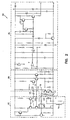
- FIG. 7 illustrates a schematic diagram of the apparatus, shown in Figure 6, in accordance with one embodiment.
- Transistors Q1, Q2, and Q3, and resistors R1, R2, and R6 form the voltage controlled current source 604, shown in Figure 6, to drive the LC tank 602, also shown in Figure 6.
- Q4 and R5 form a voltage follower to provide positive feedback.
- Q7, Q8, R3, and R4 provide a direct current biasing for the voltage follower and Q3.
- C2 is operates as an alternating current coupler to block an induced sixty hertz alternating current voltage but allows high frequency oscillation signals to pass.
- Q5, R7, R8, and C4 form the an integrator to generate a direct current signal proportional to the amplitude of the oscillation signal.
- This direct current signal is coupled to the voltage controlled current source 604 to control the current gain of the voltage controlled current source 604 through circuits formed by Q9, Q10, R9, R10, R11, R12, and R13.
- the second integrator provides an output signal to a Schmitt trigger and a delay circuit. Use of two integrators allows for a separately adjustable time constant to achieve substantially useful dynamic behavior and to substantially avoid excess loop oscillation.
- the invention discloses an apparatus including a first circuit, a second circuit, and a capacitor.
- the first circuit includes a sense element.
- the capacitor couples the first circuit to the second circuit.
- the first feedback path couples the second circuit to the first circuit.
- the second feedback path couples the second circuit to the first circuit.
- a method includes generating, for an oscillator signal having an amplitude and a gain, a substantially direct current signal related to an amplitude, and controlling the gain with the substantially direct current signal.
Landscapes
- Physics & Mathematics (AREA)
- General Physics & Mathematics (AREA)
- Measuring Magnetic Variables (AREA)
- Electronic Switches (AREA)
- Amplifiers (AREA)
- Transforming Light Signals Into Electric Signals (AREA)
Abstract
Description
- Sensors for use in detecting targets, and more particularly, sensors for use in detecting targets in the presence of an alternating current field, such as experienced in a welding operation.
- Sensors, such as proximity sensors, are used in industrial machinery, such as welding equipment and industrial robots. Proximity sensors detect the presence of targets, such as targets formed from ferrous and non-ferrous materials. Proximity sensors are used to detect the presence of both stationary and non-stationary targets. A table for holding a work piece to be welded, such as a door panel, is an example of a stationary target. To detect a table a proximity sensor is moved toward the table until the table is detected. A moving robotic arm, such as a robotic arm moving a work piece, such as a door panel, onto a table is an example of a non-stationary target. A moving robotic arm is detected as it moves to a position near a proximity sensor.
- Unfortunately, some environments in which proximity sensors are used are electromagnetically noisy environments. For example, sensors are used in environments that include arc welders. Arc welders create an alternating current or direct current environment. Some sensors fail when used in an alternating current or direct current electromagnetic field environment. A failed sensor can cause manufacturing lines to shut down or industrial machinery to malfunction. For these and other reasons there is a need for sensors that do not fail in the presence of electrical noise or an alternating current or direct current magnetic field.
- An apparatus includes a first circuit including a sense element, a second circuit, and a capacitor to couple the first circuit to the second circuit. The apparatus further includes a first feedback path to couple the second circuit to the first circuit and a second feedback path to couple the second circuit to the first circuit. Several options of the apparatus are provided. In one option, the first circuit and the second circuit are to produce a substantially periodic signal. In another option, the sense element is connected in parallel with a capacitor. In another option, the first feedback path is to provide a substantially periodic signal to the first circuit. In another option, the second feedback path is to provide an amplitude compensation signal to the first circuit. In another option, the amplitude compensation signal is to amplitude compensate the substantially periodic signal when noise or alternating current or direct current magnetic field is detected in the sense element. In another option, the noise or an alternating current magnetic field has a frequency of about sixty hertz. In another option, the amplitude compensation signal comprises a substantially direct current signal. In another option, the periodic signal has an amplitude and the amplitude compensation signal is related to the amplitude. In another option, the capacitor is to block noise or an alternating current magnetic field having a frequency of substantially sixty hertz. In another option, the sense element comprises a coil including a magnetic core. In another option, the magnetic core comprises a ferromagnetic material.
- A method is provided that includes generating, for an oscillator signal having an amplitude and a gain, a substantially direct current signal related to an amplitude, and controlling the gain with the substantially direct current signal. Several options of the method are provided. In one option, for the oscillator signal having the amplitude and the gain, generating the substantially direct current signal related to the amplitude, comprises filtering the oscillator signal. In another option, the method further includes controlling the gain in response to noise or an alternating current or direct current magnetic field in a sense element.
- A system is provided that includes a first circuit including a sense element, a second circuit, a capacitor to couple the first circuit to the second circuit and a first feedback path to couple the second circuit to the first circuit and a second feedback path to couple the second circuit to the first circuit, and a target to be detected by the sense element. Several options are provided. In one option, the oscillator generates an oscillator signal and a gain control signal and the oscillator amplitude compensates the oscillator signal when noise or an alternating current or direct current magnetic field is detected in the sense element and a target is detected by the sense element. In another option, the target comprises a moveable structure to be detected by the sense element. In still another option, the moveable structure includes a welding unit. In another option, the target comprises a stationary structure to be detected by the sense element. In another option, the stationary structure comprises an arc welding unit.
- These and other embodiments, aspects, advantages, and features will be set forth in part in the description which follows, and in part will become apparent to those skilled in the art by reference to the following description and referenced drawings or by practice thereof. The aspects, advantages, and features are realized and attained by means of the instrumentalities, procedures, and combinations particularly pointed out in the appended claims and their equivalents.
-
- Figure 1A
- illustrates a block diagram of an apparatus including a first circuit, a sense element, a second circuit, and a capacitor to couple the first circuit to the second circuit in accordance with one embodiment..
- Figure 1B
- illustrates the sense element, shown in Figure 1A, including a coil and a magnetic core in accordance with one embodiment.
- Figure 2
- illustrates a schematic diagram of an apparatus including the first circuit, shown in Figure 1A, the sense element, shown in Figure 1A, the second circuit, shown in Figure 1A, and the capacitor, shown in Figure 1A, to couple the first circuit to the second circuit, and an interface circuit in accordance with one embodiment.
- Figure 3
- illustrates a timing diagram for signals generated during the operation of the apparatus illustrated in the schematic diagram shown in Figure 2 in accordance with one embodiment.
- Figure 4
- illustrates a flow diagram of a method for compensating for noise or an alternating current or direct current magnetic field in an oscillator signal in accordance with one embodiment.
- Figure 5
- illustrates a block diagram of a system including the first circuit, shown in Figure 1A, the sense element, shown in Figure 1A, the second circuit, shown in Figure 1A, and the capacitor, shown in Figure 1A, to couple the first circuit to the second circuit. and a target in accordance with one embodiment.
- Figure 6
- illustrates a block diagram of an apparatus including an LC tank, a voltage controlled current source, an amplifier, an integrator, and an output circuit in accordance with one embodiment.
- Figure 7
- illustrates a schematic diagram of the apparatus, shown in Figure 6, in accordance with one embodiment.
- In the following detailed description, reference is made to the accompanying drawings, which form a part hereof, and in which is shown by way of illustration specific embodiments in which the invention may be practiced. These embodiments are described in sufficient detail to enable those skilled in the art to practice the invention, and it is to be understood that other embodiments may be utilized and that structural changes may be made without departing from the spirit and scope of the present invention. Therefore, the following detailed description is not to be taken in a limiting sense, and the scope is defmed by the appended claims.
- Figure 1A illustrates a block diagram of an
apparatus 100 including afirst circuit 102, asense element 104, asecond circuit 106, and acapacitor 108 to couple thefirst circuit 102 to thesecond circuit 104 in accordance with one embodiment. Thefirst circuit 102 includesfeedback ports second circuit 106 includesfeedback ports apparatus 100 further includes afirst feedback path 118 to couple thesecond circuit 106 at thefeedback port 114 to thefirst circuit 102 at thefeedback port 110. Theapparatus 100 includes asecond feedback path 120 to couple thesecond circuit 106 at thefeedback port 116 to thefirst circuit 102 at thefeedback port 112. Thefirst circuit 102 includes afirst circuit port 122. Thesecond circuit 106 includes asecond circuit port 124. Thecapacitor 108 couples thefirst circuit port 122 to thesecond circuit port 124. Thecapacitor 108 blocks noise from being coupled to thesecond circuit 106. In some embodiments, thecapacitor 108 blocks noise having a frequency of sixty hertz. - Figure 1B illustrates the
sense element 104, shown in Figure 1A, including acoil 126 and amagnetic core 128 in accordance with one embodiment. A conductive material, such as a litzt wire, which is a woven wire, is suitable for use in the fabrication of thecoil 126. In some embodiments, thecoil 126 is a discrete coil. In some embodiments, thecoil 126 is an integrated circuit coil and fabricated on a printed circuit board. An integrated circuit coil is a coil fabricated with the same processes, such as the processes used to form the integrated circuits coupled to the coil, and on the same printed circuit board as the integrated circuits coupled to the coil. Ferrite, a ferromagnetic material, is an exemplary material suitable for use in connection with the fabrication of themagnetic core 128. Ferrite is suitable for use as a core material for a discrete coil or for an integrated circuit coil. - Referring again to Figure 1A, in operation, the
first circuit 102 and thesecond circuit 106 produce a substantially periodic signal. Thefirst feedback path 118 provides a substantially periodic signal to thefirst circuit 102. Thesecond feedback path 120 provides an amplitude compensation signal to thefirst circuit 102. The amplitude compensation signal includes a substantially direct current signal. A substantially direct current signal is a current signal that has a frequency spectrum that is substantially free of non-zero frequency components. The amplitude compensation signal is related to the amplitude of the substantially periodic signal. The amplitude compensation signal amplitude compensates the substantially periodic signal when noise or an alternating current or direct current magnetic field is detected in thesense element 104. If noise or an alternating current or direct current magnetic field suppresses the amplitude of the substantially periodic signal, then the amplitude compensation signal boosts the amplitude of the substantially periodic signal. In some embodiments, the noise or an alternating current magnetic field has a frequency of about sixty hertz. - Figure 2 illustrates a schematic diagram of an
apparatus 200 including thefirst circuit 102, shown in Figure 1A, thesense element 104, shown in Figure 1A, thesecond circuit 106, shown in Figure 1A, and thecapacitor 108, shown in Figure 1A, to couple thefirst circuit 102 to thesecond circuit 106, and an interface circuit 202 in accordance with one embodiment. Thefirst circuit 102 includesfeedback ports second circuit 106 includesfeedback ports apparatus 100 further includes afirst feedback path 118 to couple thesecond circuit 106 at thefeedback port 114 to thefirst circuit 102 at thefeedback port 110. Theapparatus 200 includes asecond feedback path 120 to couple thesecond circuit 106 at thefeedback port 116 to thefirst circuit 102 at thefeedback port 112. Thefirst circuit 102 includes afirst circuit port 122. Thesecond circuit 106 includes asecond circuit port 124. Thecapacitor 108 couples thefirst circuit port 122 to thesecond circuit port 124. Thecapacitor 108 blocks noise from being coupled to thesecond circuit 106. In some embodiments, thecapacitor 108 blocks noise having a frequency of sixty hertz. - The interface circuit 202 receives and processes a substantially periodic signal to provide a target detected signal at the apparatus output port 204. In some embodiments, interface circuit 202 includes comparators and current output circuits at the output port 204.
- Figure 3 illustrates a timing diagram 300 for signals generated during the operation of the
apparatus 200 illustrated in the schematic diagram shown in Figure 2 in accordance with one embodiment. Referring again to Figure 2, the nodes V1, V2, V3, Vsh1, and Vsh2 are shown in Figure 2. Referring again to Figure 3, the signals, as shown in Figure 3 are associated with the nodes V1, V2, V3, Vsh1, and Vsh2 of Figure 2. As can be seen in Figure 3, V1, a substantially periodic signal, decreases in amplitude when a target is present, which is indicated by a positive active target "present" signal, shown in Figure 3. When a target is present, V1 drops below Vsh1, which allows V2 to increase in amplitude beyond the threshold Vsh2. When V2 crosses threshold Vsh2, V3, the output signal of theapparatus 200, shown in Figure 2, turns on. Theapparatus 200, shown in Figure 2, provides for the detection and generation of a signal in the presence of noise or an alternating current magnetic field, such as the sixty hertz field signal, also shown in Figure 3. - Figure 4 illustrates a flow diagram of a
method 400 for compensating for noise or an alternating current magnetic field in an oscillator signal in accordance with one embodiment. Themethod 400 includes generating, for an oscillator signal having an amplitude and a gain, a substantially direct current signal related to an amplitude (block 402), and controlling the gain with the substantially direct current signal (block 404). In some embodiments, generating, for the oscillator signal having the amplitude and the gain, the substantially direct current signal related to the amplitude, includes filtering the oscillator signal. In some embodiments, themethod 400 further includes controlling the gain in response to noise or an alternating current magnetic field in a sense element. - Figure 5 illustrates a block diagram of a
system 500 including thefirst circuit 102, shown in Figure 1A, thesense element 104, shown in Figure 1A, thesecond circuit 106, shown in Figure 1A, and thecapacitor 108, shown in Figure 1A, to couple thefirst circuit 102 to thesecond circuit 106, and atarget 502 in accordance with one embodiment. Thefirst circuit 102 includesfeedback ports second circuit 106 includesfeedback ports apparatus 100 further includes afirst feedback path 118 to couple thesecond circuit 106 at thefeedback port 114 to thefirst circuit 102 at thefeedback port 110. Theapparatus 100 includes asecond feedback path 120 to couple thesecond circuit 106 at thefeedback port 116 to thefirst circuit 102 at thefeedback port 112. Thefirst circuit 102 includes afirst circuit port 122. Thesecond circuit 106 includes asecond circuit port 124. Thecapacitor 108 couples thefirst circuit port 122 to thesecond circuit port 124. Theapparatus 100 further includes afirst feedback path 118 to couple thesecond circuit 106 to thefirst circuit 102 and asecond feedback path 112 to couple thesecond circuit 106 to thefirst circuit 102. - The
target 502 is not limited to a particular target. In some embodiments, thetarget 502 includes a moveable structure to be detected by thesense element 104. In some embodiments, the moveable structure includes a welding unit. In some embodiments, thetarget 502 includes a stationary structure to be detected by thesense element 104. Exemplary stationary structures includes tables and automobile bodies on an assembly line. In some embodiments, the stationary structure includes an arc welding unit. - In operation, the
first circuit 102 and thesecond circuit 106 generate a substantially periodic signal. Thetarget 502 is detected by thesense element 104. In some embodiments, thetarget 502 is coupled to thesense element 104 at detection time electromagnetically. When the substantially periodic signal is subjected to noise, thefirst circuit 102 and thesecond circuit 106 amplitude compensate the substantially periodic signal. - Figure 6 illustrates a block diagram of an
apparatus 600 including anLC tank 602, a voltage controlledcurrent source 604, anamplifier 606, anintegrator 608, and anoutput circuit 610 in accordance with one embodiment. TheLC tank 602 is coupled to the voltage controlledcurrent source 604 and theamplifier 606. Theamplifier 606 is coupled to the voltage controlledcurrent source 604 and theintegrator 608. Theintegrator 608 is coupled to the voltage controlledcurrent source 604 and theoutput circuit 610. In some embodiments, theamplifier 606 includes biasing. In some embodiments, acapacitor 612 couples theLC tank 602 to theamplifier 606. - In operation, the voltage controlled
current source 604 drives theLC tank 602. An oscillation signal, such as a high frequency oscillation signal, formed across theLC tank 602 is coupled to theamplifier 606 by thecapacitor 612. An induced sixty hertz voltage is blocked by thecapacitor 612 or a highpass filter and will have substantially no effect on theamplifier 606 or any biasing circuits included with theamplifier 606. The output of theamplifier 602 is coupled to the voltage controlledcurrent source 604 to control the voltage controlledcurrent source 604 and to form a positive feedback loop required for oscillation. The direct current output of theintegrator 608 is coupled to the voltage controlledcurrent source 604 to control the current gain of the voltage controlledcurrent source 604 and to form a second feed back loop. The purpose of the second feedback loop is to increase the current gain of the oscillator when the output of theintegrator 608 is below a certain level (this level is below the trip level of the Schmitt trigger to avoid reducing sensor sensitivity to the target) to sustain the oscillation. This speeds up the oscillator and make it bounce up at a substantial rate for a sixty hertz alternating current field crossing zero. A delay circuit and a Schmitt trigger provide theapparatus 600 with magnetic field immunity. - The
apparatus 600 provides substantial immunity to false trigger events caused by core saturation, such as ferrite core saturation, which damps the oscillator. Theapparatus 600 also provides substantial immunity to false trigger events caused by induced voltage in the coil, which can change the operating point of the amplifier. - Figure 7 illustrates a schematic diagram of the apparatus, shown in Figure 6, in accordance with one embodiment. Transistors Q1, Q2, and Q3, and resistors R1, R2, and R6 form the voltage controlled
current source 604, shown in Figure 6, to drive theLC tank 602, also shown in Figure 6. Q4 and R5 form a voltage follower to provide positive feedback. Q7, Q8, R3, and R4 provide a direct current biasing for the voltage follower and Q3. C2 is operates as an alternating current coupler to block an induced sixty hertz alternating current voltage but allows high frequency oscillation signals to pass. Q5, R7, R8, and C4 form the an integrator to generate a direct current signal proportional to the amplitude of the oscillation signal. This direct current signal is coupled to the voltage controlledcurrent source 604 to control the current gain of the voltage controlledcurrent source 604 through circuits formed by Q9, Q10, R9, R10, R11, R12, and R13. The second integrator provides an output signal to a Schmitt trigger and a delay circuit. Use of two integrators allows for a separately adjustable time constant to achieve substantially useful dynamic behavior and to substantially avoid excess loop oscillation. - It is to be understood that the above description is intended to be illustrative, and not restrictive. Furthermore, it should be noted that the embodiments, and various options described above and illustrated in the drawings, may be selectively combined to form additional embodiments. Many other embodiments will be apparent to those of skill in the art upon reviewing the above description. The scope should, therefore, be determined with reference to the appended claims, along with the full scope of equivalents to which such claims are entitled.
In summary the invention discloses an apparatus including a first circuit, a second circuit, and a capacitor. The first circuit includes a sense element. The capacitor couples the first circuit to the second circuit. The first feedback path couples the second circuit to the first circuit. And the second feedback path couples the second circuit to the first circuit. A method includes generating, for an oscillator signal having an amplitude and a gain, a substantially direct current signal related to an amplitude, and controlling the gain with the substantially direct current signal.
Claims (20)
- An apparatus comprising:a first circuit including a sense element;a second circuit; anda capacitor to couple the first circuit to the second circuit and a first feedback path to couple the second circuit to the first circuit and a second feedback path to couple the second circuit to the first circuit.
- The apparatus of claim 1, the first circuit and the second circuit to produce a substantially periodic signal.
- The apparatus of claim 1 or 2, wherein the sense element is connected in parallel with a capacitor.
- The apparatus of claim 1, 2 or 3 the first feedback path to provide a substantially periodic signal to the first circuit.
- The apparatus of one of claims 1 to 4, the second feedback path to provide an amplitude compensation signal to the first circuit.
- The apparatus of claim 5, the amplitude compensation signal to amplitude compensate the substantially periodic signal when noise or an alternating current or direct current magnetic field is detected in the sense element.
- The apparatus of claim 6, wherein the noise or an alternating current magnetic field has a frequency of about sixty hertz.
- The apparatus of claim 5, 6, or 7wherein the amplitude compensation signal comprises a substantially direct current signal.
- The apparatus of one of claims 2 to 8, wherein the periodic signal has an amplitude and the amplitude compensation signal is related to the amplitude.
- The apparatus of one of claims 1 to 9, the capacitor to block noise having a frequency of substantially sixty hertz.
- The apparatus of one of claims 1 to 10, wherein the sense element comprises a coil including a magnetic core.
- The apparatus of claim 11, wherein the magnetic core comprises a ferromagnetic material.
- A method comprising:generating, for an oscillator signal having an amplitude and a gain, a substantially direct current signal related to an amplitude; andcontrolling the gain with the substantially direct current signal.
- The method of claim 13, wherein generating, for the oscillator signal having the amplitude and the gain, the substantially direct current signal related to the amplitude, comprises filtering the oscillator signal.
- The method of claim 13 or 14, further comprising controlling the gain in response to noise or an alternating current or direct current magnetic field in a sense element.
- A system comprising:a first circuit including a sense element;a second circuit;a capacitor to couple the first circuit to the second circuit and a first feedback path to couple the second circuit to the first circuit and a second feedback path to couple the second circuit to the first circuit; anda target to be detected by the sense element.
- The system of claim 16, wherein the target comprises a moveable structure to be detected by the sense element.
- The system of claim 17, wherein the moveable structure includes a welding unit.
- The system of claim 16, 17, or 18 wherein the target comprises a stationary structure to be detected by the sense element.
- The system of claim 18 or 19, wherein the stationary structure comprises an arc welding unit.
Applications Claiming Priority (1)
| Application Number | Priority Date | Filing Date | Title |
|---|---|---|---|
| US10/936,956 US7274189B2 (en) | 2004-09-09 | 2004-09-09 | Sensor and method |
Publications (3)
| Publication Number | Publication Date |
|---|---|
| EP1635146A2 true EP1635146A2 (en) | 2006-03-15 |
| EP1635146A3 EP1635146A3 (en) | 2009-01-07 |
| EP1635146B1 EP1635146B1 (en) | 2013-08-14 |
Family
ID=35517480
Family Applications (1)
| Application Number | Title | Priority Date | Filing Date |
|---|---|---|---|
| EP05019434.9A Ceased EP1635146B1 (en) | 2004-09-09 | 2005-09-07 | Sensor and method |
Country Status (2)
| Country | Link |
|---|---|
| US (1) | US7274189B2 (en) |
| EP (1) | EP1635146B1 (en) |
Cited By (1)
| Publication number | Priority date | Publication date | Assignee | Title |
|---|---|---|---|---|
| EP2429077A1 (en) * | 2010-09-14 | 2012-03-14 | Optosys SA | Inductive proximity switch |
Families Citing this family (10)
| Publication number | Priority date | Publication date | Assignee | Title |
|---|---|---|---|---|
| US7675285B2 (en) * | 2004-09-09 | 2010-03-09 | Rockwell Automation Technologies, Inc. | Sensor and method including noise compensation |
| US20070257667A1 (en) * | 2006-05-03 | 2007-11-08 | Thaddeus Schroeder | Position sensors and arrays utilizing back EMF |
| EP2099134B1 (en) * | 2008-03-06 | 2012-05-23 | Pepperl + Fuchs GmbH | Method for recognising a pre-attenuation of an inductive sensor and inductive sensor |
| US8188730B2 (en) * | 2008-09-10 | 2012-05-29 | Rockwell Automation Technologies, Inc. | Method and system for inductive proximity sensing that includes mounting effect compensation |
| US8593156B2 (en) | 2010-11-22 | 2013-11-26 | General Electric Company | Sensor assembly and microwave emitter for use in a sensor assembly |
| US8531191B2 (en) | 2010-11-22 | 2013-09-10 | General Electric Company | Sensor assembly and methods of measuring a proximity of a machine component to a sensor |
| US8854052B2 (en) | 2010-11-22 | 2014-10-07 | General Electric Company | Sensor assembly and method of measuring the proximity of a machine component to a sensor |
| US8624603B2 (en) | 2010-11-22 | 2014-01-07 | General Electric Company | Sensor assembly and methods of adjusting the operation of a sensor |
| US8482456B2 (en) | 2010-12-16 | 2013-07-09 | General Electric Company | Sensor assembly and method of measuring the proximity of a machine component to an emitter |
| US8742319B2 (en) | 2011-12-13 | 2014-06-03 | General Electric Company | Sensor and inspection system deploying an optical conduit |
Citations (1)
| Publication number | Priority date | Publication date | Assignee | Title |
|---|---|---|---|---|
| US5953822A (en) | 1996-12-24 | 1999-09-21 | Rescue Technology, Inc. | Rescue tool |
Family Cites Families (9)
| Publication number | Priority date | Publication date | Assignee | Title |
|---|---|---|---|---|
| BE751108R (en) * | 1969-06-06 | 1970-11-03 | Berliet Automobiles | DEVICE FOR THE PRECISE MEASUREMENT OF THE SPECIFIC CONSUMPTION OF COMBUSTION ENGINES |
| IT1128202B (en) * | 1980-01-10 | 1986-05-28 | Fiat Ricerche | DEVICE FOR DETECTION OF THE POSITION OF AN AUTOMATIC ARC WELDING TORCH |
| US4385297A (en) * | 1980-01-14 | 1983-05-24 | Schmitt Wilhelm E | Arrangement for sensing proximity of a reciprocating member |
| US5952822A (en) * | 1996-10-24 | 1999-09-14 | Allen-Bradley Company, Llc | Method and apparatus for proximity sensing in the presence of an external field |
| US6208134B1 (en) * | 1999-09-30 | 2001-03-27 | Honeywell International Inc | Interference-tolerant proximity sensor system having a resonance-tracking impedance analyzer |
| GB0006144D0 (en) * | 2000-03-14 | 2000-05-03 | Isis Innovation | Position and electromagnetic field sensor |
| WO2001076806A1 (en) * | 2000-04-10 | 2001-10-18 | Mitsubishi Heavy Industries, Ltd. | Welding system |
| US6617845B1 (en) | 2000-04-28 | 2003-09-09 | Rockwell Automation Technologies, Inc. | Proximity sensor resistant to environmental effects |
| US7675285B2 (en) | 2004-09-09 | 2010-03-09 | Rockwell Automation Technologies, Inc. | Sensor and method including noise compensation |
-
2004
- 2004-09-09 US US10/936,956 patent/US7274189B2/en not_active Expired - Lifetime
-
2005
- 2005-09-07 EP EP05019434.9A patent/EP1635146B1/en not_active Ceased
Patent Citations (1)
| Publication number | Priority date | Publication date | Assignee | Title |
|---|---|---|---|---|
| US5953822A (en) | 1996-12-24 | 1999-09-21 | Rescue Technology, Inc. | Rescue tool |
Cited By (2)
| Publication number | Priority date | Publication date | Assignee | Title |
|---|---|---|---|---|
| EP2429077A1 (en) * | 2010-09-14 | 2012-03-14 | Optosys SA | Inductive proximity switch |
| US8947103B2 (en) | 2010-09-14 | 2015-02-03 | Optosys Sa | Inductive proximity switch |
Also Published As
| Publication number | Publication date |
|---|---|
| EP1635146A3 (en) | 2009-01-07 |
| US20060049827A1 (en) | 2006-03-09 |
| US7274189B2 (en) | 2007-09-25 |
| EP1635146B1 (en) | 2013-08-14 |
Similar Documents
| Publication | Publication Date | Title |
|---|---|---|
| EP1635146B1 (en) | Sensor and method | |
| US4857842A (en) | Temperature compensated hall effect position sensor | |
| US8258777B2 (en) | Inductive proximity sensor | |
| KR100569748B1 (en) | Powerline noise filter | |
| US5498958A (en) | Inductive proximity sensor with periodic switching for sensing the presence of objects | |
| KR20010060177A (en) | Magnetic levitation control apparatus | |
| WO2000043795A1 (en) | Current sensor | |
| US20060238199A1 (en) | Systems and methods useful for detecting presence and / or location of various materials | |
| US20030071638A1 (en) | Inductive proximity sensor | |
| US4088379A (en) | Variable permanent magnet suspension system | |
| US6859140B2 (en) | Independently excited proximity or presence switch arrangement | |
| US7675285B2 (en) | Sensor and method including noise compensation | |
| JP3986559B2 (en) | Magnetic field sensor | |
| US3732503A (en) | Proximity switch including variable frequency oscillator with ferrite control element | |
| US4841163A (en) | Proximity switch immune to interference fields | |
| JP3649595B2 (en) | Magnetic levitation controller | |
| US20120081107A1 (en) | Inductive proximity sensor with active circuit to cancel stray fields | |
| KR101850278B1 (en) | Inductive proximity switch | |
| US6664781B2 (en) | Inductive proximity sensor with a differentially coupled energy source | |
| US4038609A (en) | Replica bridge sensing circuit | |
| JP3014264B2 (en) | Steel plate vibration control device | |
| KR940003087B1 (en) | Wire cut electric discharge machining device | |
| JPH05118329A (en) | Magnetic bearing device | |
| US8427137B2 (en) | Magnetostrictive displacement transducer with suppression of switching power supply noise | |
| JP3205623B2 (en) | Magnetic levitation transfer device |
Legal Events
| Date | Code | Title | Description |
|---|---|---|---|
| PUAI | Public reference made under article 153(3) epc to a published international application that has entered the european phase |
Free format text: ORIGINAL CODE: 0009012 |
|
| AK | Designated contracting states |
Kind code of ref document: A2 Designated state(s): AT BE BG CH CY CZ DE DK EE ES FI FR GB GR HU IE IS IT LI LT LU LV MC NL PL PT RO SE SI SK TR |
|
| AX | Request for extension of the european patent |
Extension state: AL BA HR MK YU |
|
| PUAL | Search report despatched |
Free format text: ORIGINAL CODE: 0009013 |
|
| AK | Designated contracting states |
Kind code of ref document: A3 Designated state(s): AT BE BG CH CY CZ DE DK EE ES FI FR GB GR HU IE IS IT LI LT LU LV MC NL PL PT RO SE SI SK TR |
|
| AX | Request for extension of the european patent |
Extension state: AL BA HR MK YU |
|
| 17P | Request for examination filed |
Effective date: 20090707 |
|
| AKX | Designation fees paid |
Designated state(s): CH DE LI |
|
| 17Q | First examination report despatched |
Effective date: 20090817 |
|
| GRAP | Despatch of communication of intention to grant a patent |
Free format text: ORIGINAL CODE: EPIDOSNIGR1 |
|
| GRAS | Grant fee paid |
Free format text: ORIGINAL CODE: EPIDOSNIGR3 |
|
| GRAA | (expected) grant |
Free format text: ORIGINAL CODE: 0009210 |
|
| AK | Designated contracting states |
Kind code of ref document: B1 Designated state(s): CH DE LI |
|
| REG | Reference to a national code |
Ref country code: CH Ref legal event code: EP |
|
| REG | Reference to a national code |
Ref country code: DE Ref legal event code: R096 Ref document number: 602005040820 Country of ref document: DE Effective date: 20131010 |
|
| PLBE | No opposition filed within time limit |
Free format text: ORIGINAL CODE: 0009261 |
|
| STAA | Information on the status of an ep patent application or granted ep patent |
Free format text: STATUS: NO OPPOSITION FILED WITHIN TIME LIMIT |
|
| 26N | No opposition filed |
Effective date: 20140515 |
|
| REG | Reference to a national code |
Ref country code: DE Ref legal event code: R097 Ref document number: 602005040820 Country of ref document: DE Effective date: 20140515 |
|
| PGFP | Annual fee paid to national office [announced via postgrant information from national office to epo] |
Ref country code: CH Payment date: 20150928 Year of fee payment: 11 |
|
| PGFP | Annual fee paid to national office [announced via postgrant information from national office to epo] |
Ref country code: DE Payment date: 20150929 Year of fee payment: 11 |
|
| REG | Reference to a national code |
Ref country code: DE Ref legal event code: R119 Ref document number: 602005040820 Country of ref document: DE |
|
| REG | Reference to a national code |
Ref country code: CH Ref legal event code: PL |
|
| PG25 | Lapsed in a contracting state [announced via postgrant information from national office to epo] |
Ref country code: DE Free format text: LAPSE BECAUSE OF NON-PAYMENT OF DUE FEES Effective date: 20170401 Ref country code: CH Free format text: LAPSE BECAUSE OF NON-PAYMENT OF DUE FEES Effective date: 20160930 Ref country code: LI Free format text: LAPSE BECAUSE OF NON-PAYMENT OF DUE FEES Effective date: 20160930 |
|
| P01 | Opt-out of the competence of the unified patent court (upc) registered |
Effective date: 20230404 |