EP1635088A2 - Tensioner - Google Patents
Tensioner Download PDFInfo
- Publication number
- EP1635088A2 EP1635088A2 EP05018330A EP05018330A EP1635088A2 EP 1635088 A2 EP1635088 A2 EP 1635088A2 EP 05018330 A EP05018330 A EP 05018330A EP 05018330 A EP05018330 A EP 05018330A EP 1635088 A2 EP1635088 A2 EP 1635088A2
- Authority
- EP
- European Patent Office
- Prior art keywords
- plunger
- tensioner
- ratchet
- housing
- accommodation hole
- Prior art date
- Legal status (The legal status is an assumption and is not a legal conclusion. Google has not performed a legal analysis and makes no representation as to the accuracy of the status listed.)
- Withdrawn
Links
- 230000004308 accommodation Effects 0.000 claims abstract description 14
- CPSYWNLKRDURMG-UHFFFAOYSA-L hydron;manganese(2+);phosphate Chemical compound [Mn+2].OP([O-])([O-])=O CPSYWNLKRDURMG-UHFFFAOYSA-L 0.000 claims abstract description 12
- 238000004381 surface treatment Methods 0.000 claims abstract description 12
- XAGFODPZIPBFFR-UHFFFAOYSA-N aluminium Chemical compound [Al] XAGFODPZIPBFFR-UHFFFAOYSA-N 0.000 claims abstract description 7
- 229910052782 aluminium Inorganic materials 0.000 claims abstract description 7
- 239000007769 metal material Substances 0.000 claims abstract description 6
- XEEYBQQBJWHFJM-UHFFFAOYSA-N Iron Chemical compound [Fe] XEEYBQQBJWHFJM-UHFFFAOYSA-N 0.000 claims description 6
- 229910000831 Steel Inorganic materials 0.000 claims description 3
- 229910052742 iron Inorganic materials 0.000 claims description 3
- 239000010959 steel Substances 0.000 claims description 3
- 238000012360 testing method Methods 0.000 description 5
- 229910001060 Gray iron Inorganic materials 0.000 description 4
- 230000007547 defect Effects 0.000 description 4
- 230000005540 biological transmission Effects 0.000 description 3
- 238000006073 displacement reaction Methods 0.000 description 3
- 238000000034 method Methods 0.000 description 3
- OKTJSMMVPCPJKN-UHFFFAOYSA-N Carbon Chemical compound [C] OKTJSMMVPCPJKN-UHFFFAOYSA-N 0.000 description 2
- 239000013078 crystal Substances 0.000 description 2
- 239000010439 graphite Substances 0.000 description 2
- 229910002804 graphite Inorganic materials 0.000 description 2
- 238000004519 manufacturing process Methods 0.000 description 2
- 238000003825 pressing Methods 0.000 description 2
- 229910000838 Al alloy Inorganic materials 0.000 description 1
- 229910001018 Cast iron Inorganic materials 0.000 description 1
- 238000002048 anodisation reaction Methods 0.000 description 1
- 239000013058 crude material Substances 0.000 description 1
- ZKKLPDLKUGTPME-UHFFFAOYSA-N diazanium;bis(sulfanylidene)molybdenum;sulfanide Chemical compound [NH4+].[NH4+].[SH-].[SH-].S=[Mo]=S ZKKLPDLKUGTPME-UHFFFAOYSA-N 0.000 description 1
- 238000005868 electrolysis reaction Methods 0.000 description 1
- 238000007654 immersion Methods 0.000 description 1
- 239000000463 material Substances 0.000 description 1
- CWQXQMHSOZUFJS-UHFFFAOYSA-N molybdenum disulfide Chemical compound S=[Mo]=S CWQXQMHSOZUFJS-UHFFFAOYSA-N 0.000 description 1
- 230000001629 suppression Effects 0.000 description 1
Images

Classifications
-
- F—MECHANICAL ENGINEERING; LIGHTING; HEATING; WEAPONS; BLASTING
- F16—ENGINEERING ELEMENTS AND UNITS; GENERAL MEASURES FOR PRODUCING AND MAINTAINING EFFECTIVE FUNCTIONING OF MACHINES OR INSTALLATIONS; THERMAL INSULATION IN GENERAL
- F16H—GEARING
- F16H7/00—Gearings for conveying rotary motion by endless flexible members
- F16H7/08—Means for varying tension of belts, ropes or chains
- F16H7/0848—Means for varying tension of belts, ropes or chains with means for impeding reverse motion
-
- F—MECHANICAL ENGINEERING; LIGHTING; HEATING; WEAPONS; BLASTING
- F16—ENGINEERING ELEMENTS AND UNITS; GENERAL MEASURES FOR PRODUCING AND MAINTAINING EFFECTIVE FUNCTIONING OF MACHINES OR INSTALLATIONS; THERMAL INSULATION IN GENERAL
- F16H—GEARING
- F16H7/00—Gearings for conveying rotary motion by endless flexible members
- F16H7/08—Means for varying tension of belts, ropes or chains
- F16H2007/0802—Actuators for final output members
- F16H2007/0806—Compression coil springs
-
- F—MECHANICAL ENGINEERING; LIGHTING; HEATING; WEAPONS; BLASTING
- F16—ENGINEERING ELEMENTS AND UNITS; GENERAL MEASURES FOR PRODUCING AND MAINTAINING EFFECTIVE FUNCTIONING OF MACHINES OR INSTALLATIONS; THERMAL INSULATION IN GENERAL
- F16H—GEARING
- F16H7/00—Gearings for conveying rotary motion by endless flexible members
- F16H7/08—Means for varying tension of belts, ropes or chains
- F16H2007/0802—Actuators for final output members
- F16H2007/0812—Fluid pressure
-
- F—MECHANICAL ENGINEERING; LIGHTING; HEATING; WEAPONS; BLASTING
- F16—ENGINEERING ELEMENTS AND UNITS; GENERAL MEASURES FOR PRODUCING AND MAINTAINING EFFECTIVE FUNCTIONING OF MACHINES OR INSTALLATIONS; THERMAL INSULATION IN GENERAL
- F16H—GEARING
- F16H7/00—Gearings for conveying rotary motion by endless flexible members
- F16H7/08—Means for varying tension of belts, ropes or chains
- F16H7/0848—Means for varying tension of belts, ropes or chains with means for impeding reverse motion
- F16H2007/0853—Ratchets
Definitions
- the present invention relates to a tensioner for use in applying an appropriate tension to a timing chain in a vehicle engine, specifically relates to a tensioner in which antiseizing properties between the plunger and the tensioner housing were improved.
- a chain transmission device in which a timing chain is wrapped between sprockets respectively secured to the crankshaft and the camshaft, has been used in general purpose.
- a tensioner in order to impart appropriate pressing force to a slack side of the chain to apply appropriate tension to the chain so that vibration during running of the chain is prevented, and to follow the elongation of the chain to hold appropriate pressing force, a tensioner has been used.
- a plunger is protruded from the front end of the tensioner housing by the biasing of a spring.
- This plunger presses the back surface near a pivotable end of a tensioner lever pivotably supported on an engine body side, so that a shoe surface of the tensioner lever is brought in sliding contact with the slack side of the chain to apply tension to the chain.
- the tensioner housing As a material of the tensioner housing, which is a principal component of such a tensioner a flake graphite cast iron called as "gray cast iron" having characteristics such as excellent wear resistance, vibration absorbability, machinability and the like has been usually used. Further, to more lighten weight than the gray cast iron and also to improve antiseizing a technique has been proposed in which the tensioner housing is formed of an aluminum base metallic material such as aluminum, aluminum alloy or the like, and the surface of the tensioner housing is subjected to hard anodization to form a hard alumite layer on it, and the alumite layer is subjected to secondary electrolysis in an ammonium tetrathiomolybdate solution to precipitate molybdenum bisulfide in micropores in the layer, so called surface treatment called as "Kashima Coat” ® is performed (see for example Japanese Patent Publication No. 3226030).
- a ratchet pawl body having ratchet pawls is pivotably supported on a ratchet shaft provided in the tensioner housing and the ratchet pawls engage with ratchet teeth engraved on a plunger side surface so that the backward displacement of the plunger is prevented, particularly the following problems have been pointed.
- the object of the present invention is to provide a tensioner, which is obtained at low cost and has excellent antseizing properties and endurance.
- a tensioner having a plunger pivotably fitted into a plunger accommodation hole in a tensioner housing with the front end portion of the plunger biased outward so as to be protruded, is characterized in that the tensioner housing is formed of a cast product or an aluminum base metallic material, the plunger accommodation hole is not subjected to surface treatment and the plunger is subjected to surface treatment, which causes a crystalline manganese phosphate film to form.
- the surface treatment to generate a crystalline manganese phosphate film generally means a treatment called as a LUBRITE treatment and produces a thin manganese phosphate base passive state film having a monoclinic system crystalline structure and a thickness of about 0.5 to 15 micron on an iron steel surface of the plunger by an immersion process.
- a tensioner having a plunger pivotably fitted into a plunger accommodation hole in a tensioner housing with the front end portion of the plunger biased outward so as to be protruded, is characterized in that the tensioner housing is formed of a cast product or an aluminum base metallic material, the plunger accommodation hole is not subjected to surface treatment and the plunger is subjected to surface treatment, which causes a crystalline manganese phosphate film to form, the self-lubricating property, which the crystalline manganese phosphate film has, allows the suppression of seizing between the plunger and the tensioner housing.
- a tensioner housing side but a plunger side having a comparatively simple shape and a small size is subjected to surface treatment to form a crystalline manganese phosphate film, whereby it becomes possible to shorten the treatment time.
- the crystalline manganese phosphate film allows the covering of defects or ununiformity in the sliding surface so that the running-in process of the sliding surface is speedily effected and the noise reduction from the sliding portions is performed.
- a tensioner 1 is attached to an engine body on a slack side of a chain e.g., a timing chain, wrapped between a driving sprocket 3 rotated with a crankshaft 2 of an engine and a driven sprocket 5 fixed onto a camshaft 4.
- a chain e.g., a timing chain
- a plunger 8 is extendably and retractably protruded from the front surface of a tensioner housing 7. And the front end surface 8A of this plunger 8 presses a back surface of a tensioner lever 10 pivotably supported by a supporting shaft 9 on the engine body side, near the pivoting end of the tensioner body 10.
- a shoe surface 11 of the tensioner lever 10 makes sliding contact with a slack side of the chain 6 to apply appropriate tension to the chain 6.
- a plunger accommodation hole 12 into which the plunger 8 is extendably and retractably fit-inserted.
- the plunger 8 is formed a hollow portion 13 opened on an end surface opposite to a bottom portion of the plunger accommodation hole 12. And between the bottom surface of the hollow portion 13 and the bottom portion of the plunger accommodation hole 12 opposite to the bottom surface is provided a plunger spring 14. And this plunger spring 14 always biases the plunger 8 so that the front end of the plunger 8 is protruded from the tensioner housing 7.
- This tensioner housing 7 is formed of a cast product or an aluminum base metallic material.
- the plunger is made of iron steel, and on the surface of the plunger 8 is formed a thin thick manganese phosphate base passive film having a monoclinic system crystalline structure and a thickness of about 0.5 to 15 microns by the above-mentioned lieu-bright treatment.
- ratchet pawl body 16 On to the tensioner housing 7 is pivotably supported a ratchet pawl body 16 with a ratchet shaft 15. And on this ratchet pawl body 16 is formed ratchet pawls 18, which engage with ratchet teeth T engraved on a side surface of the plunger 8.
- ratchet pawl body 16 To the ratchet pawl body 16 is always applied a rotating bias force around the ratchet shaft 15 in a direction where the ratchet pawls 17 and 18 engage with the ratchet teeth T of the plunger 8 by a ratchet spring 19 provided between the ratchet pawl body 16 and the tensioner housing 7. And this tensioner has a structure that the engagement between these ratchet pawls 17, 18 and the ratchet teeth T blocks the backward displacement of the plunger 8.
Landscapes
- Engineering & Computer Science (AREA)
- General Engineering & Computer Science (AREA)
- Mechanical Engineering (AREA)
- Devices For Conveying Motion By Means Of Endless Flexible Members (AREA)
- Chemical Treatment Of Metals (AREA)
- Powder Metallurgy (AREA)
Abstract
Description
- The present invention relates to a tensioner for use in applying an appropriate tension to a timing chain in a vehicle engine, specifically relates to a tensioner in which antiseizing properties between the plunger and the tensioner housing were improved.
- As a transmission device for transmitting rotation between a crankshaft and a camshaft in an autombile engine, a chain transmission device, in which a timing chain is wrapped between sprockets respectively secured to the crankshaft and the camshaft, has been used in general purpose. And in this chain transmission device, in order to impart appropriate pressing force to a slack side of the chain to apply appropriate tension to the chain so that vibration during running of the chain is prevented, and to follow the elongation of the chain to hold appropriate pressing force, a tensioner has been used. In the tensioner, a plunger is protruded from the front end of the tensioner housing by the biasing of a spring. The front end of this plunger presses the back surface near a pivotable end of a tensioner lever pivotably supported on an engine body side, so that a shoe surface of the tensioner lever is brought in sliding contact with the slack side of the chain to apply tension to the chain.
- As a material of the tensioner housing, which is a principal component of such a tensioner a flake graphite cast iron called as "gray cast iron" having characteristics such as excellent wear resistance, vibration absorbability, machinability and the like has been usually used. Further, to more lighten weight than the gray cast iron and also to improve antiseizing a technique has been proposed in which the tensioner housing is formed of an aluminum base metallic material such as aluminum, aluminum alloy or the like, and the surface of the tensioner housing is subjected to hard anodization to form a hard alumite layer on it, and the alumite layer is subjected to secondary electrolysis in an ammonium tetrathiomolybdate solution to precipitate molybdenum bisulfide in micropores in the layer, so called surface treatment called as "Kashima Coat" ® is performed (see for example Japanese Patent Publication No. 3226030).
- However, there was a defect that the "gray cast iron", which has been used as a crude material of the tensioner housing of a conventional tenioner, is heavy in the weight. Further, there was another defect that the crystal of graphite contained in gray cast iron is elongated and when force is applied on the tip of the crystal a crack is easy to generate so that strength of the housing is lowered.
- Further, in a case where Kashima Coat ® treatment is performed, there was a defect that the production steps becomes complicated thereby not only to increase cost but also to add working tolerance and add tolerance of the film thickness due to Kashima Coat ® treatment, so that these production steps cannot be applied to a tensioner having sever tolerance. Further, in a case where the tensioner housing has a complicated shape, or in a case where it has micropores, there was a problem that uniform surface treatment cannot be performed in the Kashima Coat ® treatment.
- Further, in a case of a ratchet type tensioner in which a plunger is always biased by a plunger spring, a ratchet pawl body having ratchet pawls is pivotably supported on a ratchet shaft provided in the tensioner housing and the ratchet pawls engage with ratchet teeth engraved on a plunger side surface so that the backward displacement of the plunger is prevented, particularly the following problems have been pointed.
- In the case of a ratchet type tensioner, since a side force (force acting at right angle to an advancing direction of the plunger) acts in a sliding surface between a plunger and a plunger accommodation hole of a tensioner housing, which is on the opposite side to a side where the ratchet pawls engage with the ratchet teeth when the plunger is pushed into by a chain tension, the friction resistance in this sliding surface is increased. Thus, the vibration of the plunger, which is generated during engine rotation, increases friction between the tensioner housing and the plunger so that the both temperatures of the tensioner housing and the plunger are also increased to deform them. In the worst case, both of the tensioner housing and the plunger are seized so that a function of the tensioner is lost. Particularly, in a case where the tensioner is used under high load, microstroke and high frequency, the generation of seizing has been a matter of concern.
- Thus, the object of the present invention is to provide a tensioner, which is obtained at low cost and has excellent antseizing properties and endurance.
- To attain said object a tensioner, having a plunger pivotably fitted into a plunger accommodation hole in a tensioner housing with the front end portion of the plunger biased outward so as to be protruded, is characterized in that the tensioner housing is formed of a cast product or an aluminum base metallic material, the plunger accommodation hole is not subjected to surface treatment and the plunger is subjected to surface treatment, which causes a crystalline manganese phosphate film to form.
- Here, the surface treatment to generate a crystalline manganese phosphate film generally means a treatment called as a LUBRITE treatment and produces a thin manganese phosphate base passive state film having a monoclinic system crystalline structure and a thickness of about 0.5 to 15 micron on an iron steel surface of the plunger by an immersion process.
- Since a tensioner, having a plunger pivotably fitted into a plunger accommodation hole in a tensioner housing with the front end portion of the plunger biased outward so as to be protruded, is characterized in that the tensioner housing is formed of a cast product or an aluminum base metallic material, the plunger accommodation hole is not subjected to surface treatment and the plunger is subjected to surface treatment, which causes a crystalline manganese phosphate film to form, the self-lubricating property, which the crystalline manganese phosphate film has, allows the suppression of seizing between the plunger and the tensioner housing. Further, in the present invention not a tensioner housing side but a plunger side having a comparatively simple shape and a small size is subjected to surface treatment to form a crystalline manganese phosphate film, whereby it becomes possible to shorten the treatment time. Further, the crystalline manganese phosphate film allows the covering of defects or ununiformity in the sliding surface so that the running-in process of the sliding surface is speedily effected and the noise reduction from the sliding portions is performed.
- An embodiment of the present invention will be described with reference to drawings based on an example.
- FIG. 1
- is a cross-sectional view showing one example of a ratchet type tensioner, and
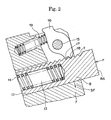
- FIG. 2
- is a partially enlarged cross-sectional view of the plunger in FIG. 1 near the front end portion thereof.
- A tensioner 1 is attached to an engine body on a slack side of a chain e.g., a timing chain, wrapped between a driving
sprocket 3 rotated with acrankshaft 2 of an engine and a drivensprocket 5 fixed onto acamshaft 4. - In this tensioner 1, a
plunger 8 is extendably and retractably protruded from the front surface of atensioner housing 7. And thefront end surface 8A of thisplunger 8 presses a back surface of atensioner lever 10 pivotably supported by a supportingshaft 9 on the engine body side, near the pivoting end of thetensioner body 10. As a result, ashoe surface 11 of thetensioner lever 10 makes sliding contact with a slack side of the chain 6 to apply appropriate tension to the chain 6. - In the
tensioner housing 7 is formed aplunger accommodation hole 12 into which theplunger 8 is extendably and retractably fit-inserted. In theplunger 8 is formed ahollow portion 13 opened on an end surface opposite to a bottom portion of theplunger accommodation hole 12. And between the bottom surface of thehollow portion 13 and the bottom portion of theplunger accommodation hole 12 opposite to the bottom surface is provided aplunger spring 14. And thisplunger spring 14 always biases theplunger 8 so that the front end of theplunger 8 is protruded from thetensioner housing 7. Thistensioner housing 7 is formed of a cast product or an aluminum base metallic material. On the other hand, the plunger is made of iron steel, and on the surface of theplunger 8 is formed a thin thick manganese phosphate base passive film having a monoclinic system crystalline structure and a thickness of about 0.5 to 15 microns by the above-mentioned lieu-bright treatment. - On to the
tensioner housing 7 is pivotably supported aratchet pawl body 16 with aratchet shaft 15. And on thisratchet pawl body 16 is formedratchet pawls 18, which engage with ratchet teeth T engraved on a side surface of theplunger 8. - To the
ratchet pawl body 16 is always applied a rotating bias force around theratchet shaft 15 in a direction where theratchet pawls 17 and 18 engage with the ratchet teeth T of theplunger 8 by aratchet spring 19 provided between theratchet pawl body 16 and the tensioner housing 7. And this tensioner has a structure that the engagement between theseratchet pawls 17, 18 and the ratchet teeth T blocks the backward displacement of theplunger 8. - Next, the results of seizing tests performed with respect to a ratchet type tensioner according to the present invention will be described. The seizing tests were performed by use of the same ratchet type tensioner as shown in FIG. 2. The test conditions are as follows.
- 1) Oil is supplied to space surrounded by the
hollow portion 13 formed in the plunger and theplunger accommodation hole 12 formed in the tensioner housing. In this case the conditions of the supplied oil were an oil temperature of 80°C and an oil pressure of 0.30 MPa. - 2) By use of a vibration testing machine, displacements of ±0.1 mm were imparted to the
front end surface 8A of the plunger by 200 times per second (200 Hz) and total 1.0 × 10⁷ times, that is for 50,000 seconds (about 14 hours). - 3) After that properties of a plunger side surface particularly an area on which the side force (force, which acts at right angle to an advancing direction of the plunger shown by SF in FIG. 2) were observed and the presence and absence of seizing were examined.
- The above-mentioned tests 1) to 3) were carried out with respect to LUBRITE treated products of the present invention and conventional products. As a result in the conventional products seizing was observed, but in the products of the present invention no seizing was observed.
-
- 1
- Ratchet type tensioner
- 2
- Crankshat
- 3
- Driving sprocket
- 4
- Camshaft
- 5
- Driven sprocket
- 6
- Chain
- 7
- Tensioner housing
- 8
- Plunger
- 8A
- Front end portion (of the plunger)
- 9
- Supporting shaft (of the tensioner lever)
- 10
- Tensioner lever
- 11
- Shoe surface (of the tensioner lever)
- 12
- Plunger accommodation hole
- 13
- Hollow portion
- 14
- Plunger spring
- 15
- Ratchet shaft
- 16
- Ratchet pawl body
- 17, 18
- Ratchet pawl
- 19
- Ratchet spring
- T
- Ratchet teeth
- SF
- Side force
Claims (4)
- Tensioner having a plunger (8) pivotably fitted into a plunger accommodation hole (12) in a tensioner housing (7) with the front end portion of the plunger (8) biased outward so as to be protruded, characterized in that
the tensioner housing (7) is formed of a cast product or an aluminum base metallic material,
the plunger accommodation hole (12) is not subjected to surface treatment and
the plunger (8) is subjected to surface treatment, which causes a crystalline manganese phosphate film to form. - Tensioner according to claim 1, characterized in that the plunger (8) is made of iron steel.
- Tensioner according to claim 1 or 2, characterized in that the plunger (8) has a manganese phosphate base passive film having a monoclinic system crystalline structure.
- Tensioner according to any of claims 1 to 3, characterized in that the plunger (8) has a manganese phosphate base passive film having a thickness of 0.5 to 15 microns.
Applications Claiming Priority (1)
| Application Number | Priority Date | Filing Date | Title |
|---|---|---|---|
| JP2004261095A JP2006077840A (en) | 2004-09-08 | 2004-09-08 | Tensioner |
Publications (2)
| Publication Number | Publication Date |
|---|---|
| EP1635088A2 true EP1635088A2 (en) | 2006-03-15 |
| EP1635088A3 EP1635088A3 (en) | 2007-11-07 |
Family
ID=35432323
Family Applications (1)
| Application Number | Title | Priority Date | Filing Date |
|---|---|---|---|
| EP05018330A Withdrawn EP1635088A3 (en) | 2004-09-08 | 2005-08-24 | Tensioner |
Country Status (3)
| Country | Link |
|---|---|
| EP (1) | EP1635088A3 (en) |
| JP (1) | JP2006077840A (en) |
| CN (1) | CN1746534A (en) |
Citations (1)
| Publication number | Priority date | Publication date | Assignee | Title |
|---|---|---|---|---|
| JP3226030B2 (en) | 1998-08-20 | 2001-11-05 | 株式会社椿本チエイン | Ratchet type tensioner |
Family Cites Families (4)
| Publication number | Priority date | Publication date | Assignee | Title |
|---|---|---|---|---|
| JPS58123882A (en) * | 1982-01-20 | 1983-07-23 | Toyota Motor Corp | Chemical conversion treatment giving manganese phosphate film |
| JP4110707B2 (en) * | 1999-07-08 | 2008-07-02 | Jfeスチール株式会社 | Galvanized steel sheet with excellent perforation resistance and press workability |
| JP2002181050A (en) * | 2000-03-16 | 2002-06-26 | Nsk Ltd | Rolling sliding member, manufacturing method thereof, and rolling sliding unit |
| JP3710124B2 (en) * | 2001-01-10 | 2005-10-26 | 株式会社椿本チエイン | Hydraulic tensioner |
-
2004
- 2004-09-08 JP JP2004261095A patent/JP2006077840A/en active Pending
-
2005
- 2005-08-24 EP EP05018330A patent/EP1635088A3/en not_active Withdrawn
- 2005-08-31 CN CN 200510097674 patent/CN1746534A/en active Pending
Patent Citations (1)
| Publication number | Priority date | Publication date | Assignee | Title |
|---|---|---|---|---|
| JP3226030B2 (en) | 1998-08-20 | 2001-11-05 | 株式会社椿本チエイン | Ratchet type tensioner |
Also Published As
| Publication number | Publication date |
|---|---|
| JP2006077840A (en) | 2006-03-23 |
| EP1635088A3 (en) | 2007-11-07 |
| CN1746534A (en) | 2006-03-15 |
Similar Documents
| Publication | Publication Date | Title |
|---|---|---|
| JP3226030B2 (en) | Ratchet type tensioner | |
| US20080207366A1 (en) | Tensioner | |
| KR102203306B1 (en) | Sliding member, chain link, and chain comprising said link | |
| US20050037879A1 (en) | Chain drive system | |
| EP1878943A2 (en) | Chain for use in automobile engine | |
| EP1881231B1 (en) | Chain for use in automobile engine | |
| US20080280716A1 (en) | Chain for use in automobile engine | |
| JP3393596B2 (en) | Roller pin material to improve cam durability | |
| US7024982B2 (en) | Combination of piston and piston ring | |
| US20010038801A1 (en) | Method of producing sintered metal sprocket and sprocket produced by the method | |
| US20150247553A1 (en) | Chain element and method for the production thereof | |
| JP2002070507A (en) | Low friction and wear resistant material and valve train for internal combustion engine | |
| JP2006077840A (en) | Tensioner | |
| GB2356234A (en) | Shoe for tensioner device and chain guide | |
| JP5898092B2 (en) | DRIVE CAM, MANUFACTURING METHOD THEREOF AND ENGINE VALVE DEVICE | |
| CN101191526A (en) | Chain for automobile engine | |
| US10174809B2 (en) | Chain element and method for the production thereof | |
| JP4736684B2 (en) | Combination sliding member | |
| EP1036956A2 (en) | Mechanical chain tensioner | |
| JP2536107B2 (en) | Sliding member | |
| JP2006104503A (en) | Press pulley | |
| JP3123258B2 (en) | Adjusting shim and manufacturing method thereof | |
| DE102004018263A1 (en) | Method for compensating for play in camshaft drive especially in IC engine has the camshaft drive wheel mounting close to the camshafts and with temperature compensation | |
| JP2004263584A (en) | Cam follower | |
| JP2004270831A (en) | Tension adjusting device for belt |
Legal Events
| Date | Code | Title | Description |
|---|---|---|---|
| PUAI | Public reference made under article 153(3) epc to a published international application that has entered the european phase |
Free format text: ORIGINAL CODE: 0009012 |
|
| AK | Designated contracting states |
Kind code of ref document: A2 Designated state(s): AT BE BG CH CY CZ DE DK EE ES FI FR GB GR HU IE IS IT LI LT LU LV MC NL PL PT RO SE SI SK TR |
|
| AX | Request for extension of the european patent |
Extension state: AL BA HR MK YU |
|
| PUAL | Search report despatched |
Free format text: ORIGINAL CODE: 0009013 |
|
| AK | Designated contracting states |
Kind code of ref document: A3 Designated state(s): AT BE BG CH CY CZ DE DK EE ES FI FR GB GR HU IE IS IT LI LT LU LV MC NL PL PT RO SE SI SK TR |
|
| AX | Request for extension of the european patent |
Extension state: AL BA HR MK YU |
|
| 17P | Request for examination filed |
Effective date: 20071106 |
|
| 17Q | First examination report despatched |
Effective date: 20080229 |
|
| STAA | Information on the status of an ep patent application or granted ep patent |
Free format text: STATUS: THE APPLICATION HAS BEEN WITHDRAWN |
|
| 18W | Application withdrawn |
Effective date: 20080421 |