EP1634776A1 - Method for determining driving task demand based on speed variability - Google Patents
Method for determining driving task demand based on speed variability Download PDFInfo
- Publication number
- EP1634776A1 EP1634776A1 EP05076979A EP05076979A EP1634776A1 EP 1634776 A1 EP1634776 A1 EP 1634776A1 EP 05076979 A EP05076979 A EP 05076979A EP 05076979 A EP05076979 A EP 05076979A EP 1634776 A1 EP1634776 A1 EP 1634776A1
- Authority
- EP
- European Patent Office
- Prior art keywords
- speed
- vehicle
- demand
- driving task
- function
- Prior art date
- Legal status (The legal status is an assumption and is not a legal conclusion. Google has not performed a legal analysis and makes no representation as to the accuracy of the status listed.)
- Granted
Links
- 238000000034 method Methods 0.000 title claims abstract description 35
- 230000006870 function Effects 0.000 description 20
- 238000001514 detection method Methods 0.000 description 8
- 230000008859 change Effects 0.000 description 5
- 238000010586 diagram Methods 0.000 description 4
- 230000008569 process Effects 0.000 description 3
- 238000003384 imaging method Methods 0.000 description 2
- 230000004044 response Effects 0.000 description 2
- 230000006399 behavior Effects 0.000 description 1
- 238000009529 body temperature measurement Methods 0.000 description 1
- 238000004364 calculation method Methods 0.000 description 1
- 230000003750 conditioning effect Effects 0.000 description 1
- 238000005259 measurement Methods 0.000 description 1
- 238000004377 microelectronic Methods 0.000 description 1
- 238000012986 modification Methods 0.000 description 1
- 230000004048 modification Effects 0.000 description 1
- 230000005855 radiation Effects 0.000 description 1
- 238000004804 winding Methods 0.000 description 1
Images


Classifications
-
- B—PERFORMING OPERATIONS; TRANSPORTING
- B60—VEHICLES IN GENERAL
- B60R—VEHICLES, VEHICLE FITTINGS, OR VEHICLE PARTS, NOT OTHERWISE PROVIDED FOR
- B60R16/00—Electric or fluid circuits specially adapted for vehicles and not otherwise provided for; Arrangement of elements of electric or fluid circuits specially adapted for vehicles and not otherwise provided for
- B60R16/02—Electric or fluid circuits specially adapted for vehicles and not otherwise provided for; Arrangement of elements of electric or fluid circuits specially adapted for vehicles and not otherwise provided for electric constitutive elements
- B60R16/023—Electric or fluid circuits specially adapted for vehicles and not otherwise provided for; Arrangement of elements of electric or fluid circuits specially adapted for vehicles and not otherwise provided for electric constitutive elements for transmission of signals between vehicle parts or subsystems
- B60R16/0231—Circuits relating to the driving or the functioning of the vehicle
- B60R16/0232—Circuits relating to the driving or the functioning of the vehicle for measuring vehicle parameters and indicating critical, abnormal or dangerous conditions
-
- G—PHYSICS
- G01—MEASURING; TESTING
- G01C—MEASURING DISTANCES, LEVELS OR BEARINGS; SURVEYING; NAVIGATION; GYROSCOPIC INSTRUMENTS; PHOTOGRAMMETRY OR VIDEOGRAMMETRY
- G01C21/00—Navigation; Navigational instruments not provided for in groups G01C1/00 - G01C19/00
- G01C21/26—Navigation; Navigational instruments not provided for in groups G01C1/00 - G01C19/00 specially adapted for navigation in a road network
-
- B—PERFORMING OPERATIONS; TRANSPORTING
- B60—VEHICLES IN GENERAL
- B60R—VEHICLES, VEHICLE FITTINGS, OR VEHICLE PARTS, NOT OTHERWISE PROVIDED FOR
- B60R21/00—Arrangements or fittings on vehicles for protecting or preventing injuries to occupants or pedestrians in case of accidents or other traffic risks
- B60R21/01—Electrical circuits for triggering passive safety arrangements, e.g. airbags, safety belt tighteners, in case of vehicle accidents or impending vehicle accidents
- B60R21/013—Electrical circuits for triggering passive safety arrangements, e.g. airbags, safety belt tighteners, in case of vehicle accidents or impending vehicle accidents including means for detecting collisions, impending collisions or roll-over
- B60R21/0134—Electrical circuits for triggering passive safety arrangements, e.g. airbags, safety belt tighteners, in case of vehicle accidents or impending vehicle accidents including means for detecting collisions, impending collisions or roll-over responsive to imminent contact with an obstacle, e.g. using radar systems
Definitions
- the present invention generally relates to object detection and driver distraction systems on a vehicle and, more particularly, relates to a system and method of determining driving task demand for a vehicle driver.
- Automotive vehicles are increasingly equipped with various electronic entertainment and information systems and mobile multimedia devices, generally referred to herein as infotainment devices and systems.
- infotainment devices and systems For example, automotive personal computing (PC) devices have been installed in vehicles to allow personal computing, web browsing, accessing e-mail, and other Internet access.
- many vehicles are equipped with navigation systems, televisions, and video game systems.
- infotainment systems typically include a human machine interface (HMI) for enabling a user to interface with the system.
- the HMI typically includes a display for viewing messages, navigational maps, video images, audio features, and other information.
- the HMI may include input controls for manipulation by a user to input commands to the infotainment system.
- the infotainment system In order to reduce distraction to the driver (operator) of the vehicle, it may be desirable to inhibit the availability of some functions (features) of the infotainment system to the driver while the vehicle is in motion. For example, it may be desirable to limit the driver's ability to manipulate the HMI for use with a navigation system or cell phone when there is excessive risk of driver distraction. It may also be desirable to control other system operations, such as controlling the response time for a collision warning system, based on activity in the surrounding environment. Collision warning systems have been proposed to warn the driver of the vehicle of objects that pose a potential obstruction to the vehicle. It may be desirable to provide different levels of control of a collision warning system based on predictability of the surrounding environment.
- the present invention provides for a system and method of assessing the driving task demand on the driver of a vehicle, and further controls one or more devices on the vehicle as a function of the assessed driving task demand.
- the method includes the steps of sensing a coverage zone in relation to a vehicle, determining a presence of one or more objects in the sensed zone, and measuring speed of each detected object in the sensed zone.
- the method also includes the steps of determining a variation in speed of one or more sensed objects and determining a driving task demand signal indicative of driving task demand as a function of the measured speed variability.
- the method may control one or more devices on the vehicle based on the assessed driving task demand signal.
- a system including a sensor for sensing a presence of one or more objects in a coverage zone in relation to a host vehicle and determining speed of each object sensed.
- the system also includes a device located on the vehicle and having a user interface for operating with an occupant in the host vehicle.
- the system further includes a controller for processing the speed signal and calculating a speed variability thereof.
- the controller further determines a driving task demand signal as a function of the speed variability and controls the device as a function of the driving task demand signal.
- an automotive vehicle 10 is generally illustrated equipped with a forward looking radar (FLR) system and a side view infrared (IR) sensing system, both for detecting target objects in coverage zone(s) proximate to the vehicle 10.
- the FLR system detects one or more objects forward of the host vehicle 10 and determines range and range rate for each detected object.
- the side view IR sensing system detects objects to the side of the host vehicle 10.
- the FLR system includes a radar sensor 12 mounted to vehicle 10 to cover a desired field of view coverage zone 14 in front of host vehicle 10.
- the radar sensor 12 may include a single sensor or a plurality of sensors arranged to cover the coverage zone 14 to sense the presence of one or more objects.
- sensor 12 may include a single scanning Doppler radar sensor that covers a narrow angle zone 14A that scans throughout the coverage zone 14.
- the radar sensor 12 may include a commercially off the-shelf microwave Doppler radar sensor capable of sensing at least twenty objects, for example.
- other detecting sensors including other types of radar sensors, video imaging cameras, and laser sensors may be employed to detect the presence of single or multiple objects, and determine the range and range rate measurement of each object.
- the radar sensor 12 measures both the range (radial distance) R to the sensed target object and further measures the range rate (time rate of change of radial distance) of each detected target object.
- the range R is the estimated radial distance between the host vehicle 10 and each sensed object.
- the range rate is the estimated rate of change of the sensed range R (i.e., speed) of the object as a function of time relative to the host vehicle 10.
- the radar sensor 12 provides both the range R and range rate data, relative to the position and speed of the host vehicle 10. However, it should be appreciated that the radar sensor 12 could otherwise provide absolute speed and range information for determining speed variability of sensed objects proximate to the host vehicle 10.
- the side view sensing system employs a thermal radiation detector 18, in the form of an infrared (IR) sensor, according to one embodiment.
- the thermal detector 18 is shown mounted on the host vehicle 10 and is configured to cover a coverage zone 20 having a field of view that extends onto a region 22 of the roadway adjacent the side of the host vehicle 10.
- the thermal detector 18 is located in the rear tail lamp assembly 16 of the host vehicle 10.
- thermal detector 18 may be located at various other locations onboard the host vehicle 10 to sense thermal energy (temperature) in the coverage zone 20 and determine the presence of one or more objects.
- the thermal detector 18 could be located in a side body panel or on an exterior rearview mirror housing of the host vehicle 10.
- the thermal detector sensor 18 may include an infrared (IR) sensor employing a thermopile sensor for sensing temperature within coverage zone 20.
- IR infrared
- thermopile sensor for sensing temperature within coverage zone 20.
- MLX90601 infrared thermometer module which is commercially available from Melexis Microelectronics Integrated Systems.
- the aforementioned infrared thermometer module employs a thermopile sensor as the infrared sensing element for recording remote temperature measurements and provides signal conditioning, linearization, and ambient temperature compensation.
- object detecting sensors may be employed in place of a thermal detector 18, including a side view radar sensor, imaging camera or other sensing devices for determining the presence of one or more objects and/or sensing a parameter that may be useful for determining speed variability of objects proximate to the host vehicle 10.
- a workload management system including the forward looking radar sensor 12 and the side view thermal detector 18.
- Each of the sensors 12 and 18 detects the presence of one or more objects in the respective coverage zones 14 and 20.
- Radar sensor 12 determines the range R from the host vehicle 10 to each detected object, and further detects the range rate relative to the host vehicle 10.
- the range and range rate signals R are input to a controller 30.
- Sensor 18 generates signal indicators of the presence of an object.
- the controller 30 processes the range and range rate signals R and for each object detected with the forward looking radar sensor 12 and the signals from the side view thermal detector 18.
- the controller 30 also receives a vehicle speed signal 24 indicative of speed of the host vehicle 10.
- the controller 30 further receives GPS signals from a global positioning system (GPS) 26 device which provides position information, time of day, and velocity information for the host vehicle 10.
- GPS global positioning system
- the controller 30 processes the input signals and determines a driving task demand signal based on speed variability of objects detected relative to the host vehicle 10.
- the controller 30 further is able to control any of a number of devices and associated functions/features employed onboard the host vehicle 10.
- an entertainment and infotainment system 36 which may include navigation, cell phone, and other devices may be controlled by controller 30 based on the driving task demand signal.
- the host vehicle 10 may include a forward collision warning system 38.
- the controller 30 may control devices associated with operation of the forward collision warning system 38 based on the determined driving task demand signal.
- the controller 30 includes a microprocessor 32 and memory 34.
- the microprocessor 32 may include a conventional microprocessor having the capability for processing algorithms and data.
- Memory 34 may include read-only memory (ROM), random access memory (RAM), flash memory, and other commercially available volatile and non-volatile memory devices.
- ROM read-only memory
- RAM random access memory
- flash memory and other commercially available volatile and non-volatile memory devices.
- a driving task demand detection routine 40 Stored within memory 34 and processed by microprocessor 32 is a driving task demand detection routine 40 for detecting speed variability and determining a driving task demand signal.
- Also stored in memory 34 are one or more system control routines 80 for controlling any of a number of vehicle system/devices based on the driving task demand signal.
- the controller 30 monitors the sensed range and range rate signals R and received from the forward looking radar sensor 12 and the signals from the side view infrared sensor, for each object detected in the corresponding coverage zones. The controller 30 then processes the range and range rate signals R and for each object detected by sensor 12 and determines the variability of speed for each object relative to the host vehicle 10. This includes calculating the change in speed of each object and calculating a speed variance signal based on a speed variance equation, according to a first embodiment. According to a second embodiment, the variance signal can be calculated based on an entropy formula.
- the controller 30 measures an average speed variability over time, which serves as a variable for predicting the surrounding environment of the host vehicle 10.
- the speed variability parameter provides an indication of the predictability of the surrounding targets relative to the host vehicle, which may be used to determine the driving task demand on the driver of the host vehicle 10. For example, when driving on a country road during the daytime with low traffic, the driving task demand is relatively low. However, when driving in an urban setting during rush hour traffic, the driving task demand is generally much higher as the predictability of nearby vehicles on the roadway creates more of an unpredictable surrounding environment. As the traffic flow increases, various segments of roadways may become bottlenecks, thereby forcing drivers to slow down. As vehicle change lanes and bottlenecks emerge and subside, the surrounding traffic may change speed erratically. This constant and unpredictable speed variation places greater demand on the driver because the driver must be prepared to rapidly respond to the dynamic traffic behavior.
- the controller 30 determines a driving task demand signal which is a prediction of the demand on the driver of the vehicle 10.
- the driving task demand signal is used to control system devices.
- devices associated with the entertainment and infotainment system 36 may be controlled to limit access thereto, thereby reducing distraction to the driver during high driving risk demand situations.
- devices associated with the forward collision warning system 38 may be controlled to act more quickly in situations where the driving task demand is relatively low, since it has been found that drivers are typically not as attentive to surrounding conditions in such situations.
- Routine 40 begins at step 42 and performs an initialization in step 44.
- the initialization may include setting the total number of forward targets N equal to zero, setting the number of frames per target n i equal to zero, setting the number of frames within a time window T, and may include other initial settings.
- routine 40 proceeds to step 46 to obtain and store range R i , range rate for each of the detected forward target objects i, the side vehicle information (30), and the host vehicle information V h for frame j.
- Frame j includes the sensed data at a particular time captured in frame j.
- routine 40 calculates the total number of detected forward targets N, the number of frames per target n i , and the speed for each detected forward target in step 48.
- the speed calculation for each detected forward target i in frame j is identified as V ij and is calculated by summing the host vehicle speed with the range rate .
- the range rate is the relative range rate of a detected object i in frame j relative to the host vehicle 10.
- routine 40 determines if the number of frame per targets n i is greater than one and, if not, sets a within-target speed variance S i 2 equal to zero in step 58, and then proceeds to compute the traffic command signal in step 68. If the number of frames per target n i is greater than one, routine 40 proceeds to decision step 60 to determine if the number of frames per target n i is greater than T-1 and, if not, proceeds to step 62 to compute the within-target speed variance S i 2 as shown as a function of an average computation of variance in speed for each detected forward target V ij and the number of frames per target n i .
- routine 40 proceeds to compute the within-target speed variance S i 2 according to the function shown in step 64 as a function of an average computation of variance in speed for each detected forward target V ij .
- the speed variance S i 2 computes the summation of n i or T target object speeds.
- routine 40 proceeds to compute the traffic demand signal in 68.
- Computation of the traffic driving task demand signal Demand j is computed as shown in the equation in step 68.
- the computation includes constants K 1 , K 2 , and K 3 .
- the variable SOD represents the number of objects detected with the side detection system. If the side view detection sensors are not available, constant K 3 could be set equal to zero.
- routine 40 advances to the next frame j+1 in step 70, and then returns to step 46 to repeat the routine 40 for each successive frame.
- the computed traffic driving task demand signal Demand can then be used in any of a number of applications to control various devices.
- routine 80 employing the driving task demand signal Demand j to control one or more devices associated with the entertainment and infotainment system 36, according to one example.
- Routine 80 begins at step 82 and proceeds to read the driving task demand signal Demand j in step 84.
- routine 80 determines if the demand signal Demand j is greater than a first threshold (Threshold 1 ) which is indicative of a high level of driving task demand. If the demand signal Demand j is greater than the first threshold, routine 80 proceeds to adjust the levels of advisory and device availability in step 88. For example, this may include selecting a severe level of distraction advisory and a low level of device availability. Thus, interface with certain devices can be limited during the severe level of distraction advisory. Additionally, the forward collision warning onset timing may be adjusted based on the driving task demand signal Demand j .
- routine 80 proceeds to decision step 90 to determine if the demand signal Demand j is greater than a second lower threshold (Threshold 2 ), which is indicative of a more moderate driving task demand situation. If the demand signal Demand j is greater than the second threshold, routine 80 proceeds to step 92 to adjust the levels of advisory and device availability to a moderate level. For example, this may include setting the distraction advisory to a moderate level and the device availability of the entertainment and infotainment system to a moderate level. The forward collision warning onset timing may also be adjusted.
- routine 80 proceeds to step 94 to adjust the levels of advisory and device availability so as to set the distraction advisory to a low level and the device availability to a high level. Additionally, the forward collision warning onset timing is also adjusted accordingly.
- routine 80 returns to step 84 to read the next demand signal Demand j and the routine 80 is repeated. Accordingly, routine 80 is able to adjust the levels of advisory and device availability of entertainment and infotainment system devices as a function of the driving task demand signal Demand j as compared to one or more threshold values.
- routine 140 determines the driving task demand signal Demand j based on speed of the host vehicle 10.
- Routine 140 begins at step 142 and performs an initialization in step 144.
- the initialization includes setting the number of frames for the host vehicle n h equal to zero and setting the number of frames within a time window T.
- routine 140 obtains and stores the host vehicle speed V h for frame j in step 146.
- routine 140 calculates the number of frames for the host vehicle n h .
- routine 140 determines if the number of frames for the host vehicle n h is greater than one and, if not, sets a speed variance S h 2 equal to zero in step 152. Routine 140 then computes the demand signal Demand j in step 160. If the number of frames for the host vehicle n h is greater than one, routine 140 proceeds to decision step 154 to determine if the number of frames for the host vehicle n h is greater than the number of frames within a time window T-1 and, if not, computes the speed variance value S h 2 as shown in step 156. The speed variance value S h 2 is computed in step 156 as a function of a summation of the host vehicle speed V hj for each frame j based on n h .
- routine 140 proceeds to compute the speed variance value S h 2 in step 158.
- the speed variance value S h 2 computation in step 158 includes computing the speed variance value S h 2 as a function of the summation of host vehicle speed V hj for each frame based on the number of frames within the time window T. Following either of steps 156 or 158, the computation of the speed variance in routine 140 proceeds to compute the traffic driving task demand signal Demand in step 160.
- Computation of the driving task demand signal Demand is computed by multiplying the speed variance value S h 2 from steps 152, 156 or 158 with a constant value K. Following computation of the demand signal Demand j , routine 140 proceeds to increment to the frame to the next frame j+1, and then returns to step 146. Accordingly, routine 140 is able to compute a driving task demand signal Demand as a function of vehicle speed, absent the use of the forward looking radar system and the side view sensing system. This provides for a less costly and less complicated detection system.
- the present invention advantageously determines a driving task demand signal as a function of speed variability, and allow control of devices as a function of the driving task demand signal. While specific equations have been shown for computing the speed variability and the demand signal, it should be appreciated that other speed variability related equations could be employed. For example, the speed variability could be computed as a function of average entropy of the surrounding traffic speed, or, alternately, as a function of the host vehicle speed. The use of entropy provides a determination as to unpredictability of the driving environment.
Landscapes
- Engineering & Computer Science (AREA)
- Radar, Positioning & Navigation (AREA)
- Remote Sensing (AREA)
- Automation & Control Theory (AREA)
- Mechanical Engineering (AREA)
- Physics & Mathematics (AREA)
- General Physics & Mathematics (AREA)
- Traffic Control Systems (AREA)
- Stored Programmes (AREA)
- Control Of Driving Devices And Active Controlling Of Vehicle (AREA)
- Control Of Vehicle Engines Or Engines For Specific Uses (AREA)
Abstract
Description
- The present invention generally relates to object detection and driver distraction systems on a vehicle and, more particularly, relates to a system and method of determining driving task demand for a vehicle driver.
- Automotive vehicles are increasingly equipped with various electronic entertainment and information systems and mobile multimedia devices, generally referred to herein as infotainment devices and systems. For example, automotive personal computing (PC) devices have been installed in vehicles to allow personal computing, web browsing, accessing e-mail, and other Internet access. Additionally, many vehicles are equipped with navigation systems, televisions, and video game systems. These and other infotainment systems typically include a human machine interface (HMI) for enabling a user to interface with the system. The HMI typically includes a display for viewing messages, navigational maps, video images, audio features, and other information. In addition, the HMI may include input controls for manipulation by a user to input commands to the infotainment system.
- In order to reduce distraction to the driver (operator) of the vehicle, it may be desirable to inhibit the availability of some functions (features) of the infotainment system to the driver while the vehicle is in motion. For example, it may be desirable to limit the driver's ability to manipulate the HMI for use with a navigation system or cell phone when there is excessive risk of driver distraction. It may also be desirable to control other system operations, such as controlling the response time for a collision warning system, based on activity in the surrounding environment. Collision warning systems have been proposed to warn the driver of the vehicle of objects that pose a potential obstruction to the vehicle. It may be desirable to provide different levels of control of a collision warning system based on predictability of the surrounding environment.
- When the driver is commanding a vehicle on a straight country road with no traffic during the daytime, there is less demand on the driver for attention. In this situation, the driver typically can predict what will happen within the next few seconds, despite a brief driver distraction. Conversely, when driving on a multi-lane winding road with erratic traffic, the driver is subjected to a higher driving task demand that requires more attention. In this situation, when the driver is distracted, there is a higher probability that a quicker response may be required. Conventional infotainment control systems and collision warning systems generally do not provide dynamic control of various features on a vehicle to permit the driver to engage distracting features in low traffic on straight roads, and to shield the driver against excessive distraction when driving in higher risk situations.
- It is therefore desirable to provide for a method and system of assessing the driving task demand on the driver of a vehicle. It is further desirable to provide for a system and method that may dynamically adjust one or more devices on the vehicle based on the assessed driving task demand.
- The present invention provides for a system and method of assessing the driving task demand on the driver of a vehicle, and further controls one or more devices on the vehicle as a function of the assessed driving task demand. According to one aspect of the present invention, the method includes the steps of sensing a coverage zone in relation to a vehicle, determining a presence of one or more objects in the sensed zone, and measuring speed of each detected object in the sensed zone. The method also includes the steps of determining a variation in speed of one or more sensed objects and determining a driving task demand signal indicative of driving task demand as a function of the measured speed variability. According to a further aspect of the present invention, the method may control one or more devices on the vehicle based on the assessed driving task demand signal.
- According to a further aspect of the present invention, a system is provided including a sensor for sensing a presence of one or more objects in a coverage zone in relation to a host vehicle and determining speed of each object sensed. The system also includes a device located on the vehicle and having a user interface for operating with an occupant in the host vehicle. The system further includes a controller for processing the speed signal and calculating a speed variability thereof. The controller further determines a driving task demand signal as a function of the speed variability and controls the device as a function of the driving task demand signal.
- These and other features, advantages and objects of the present invention will be further understood and appreciated by those skilled in the art by reference to the following specification, claims and appended drawings.
- The present invention will now be described, by way of example, with reference to the accompanying drawings, in which:
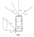
- FIG. 1 is a top view of a vehicle employing a forward looking radar and side infrared sensing system for use in assessing driving task demand according to the present invention;
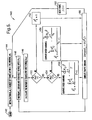
- FIG. 2 is a block diagram illustrating a system for assessing driving task demand and controlling one or more devices on the vehicle;
- FIG. 3 is a flow diagram illustrating a routine for determining driving task demand according to a first embodiment;
- FIG. 4 is a flow diagram illustrating a routine for controlling a device as a function of the driving task demand signal; and
- FIG. 5 is a flow diagram illustrating a routine for determining driving task demand according to a second embodiment.
- Referring to FIG. 1, an
automotive vehicle 10 is generally illustrated equipped with a forward looking radar (FLR) system and a side view infrared (IR) sensing system, both for detecting target objects in coverage zone(s) proximate to thevehicle 10. The FLR system detects one or more objects forward of thehost vehicle 10 and determines range and range rate for each detected object. The side view IR sensing system detects objects to the side of thehost vehicle 10. - The FLR system includes a
radar sensor 12 mounted tovehicle 10 to cover a desired field ofview coverage zone 14 in front ofhost vehicle 10. Theradar sensor 12 may include a single sensor or a plurality of sensors arranged to cover thecoverage zone 14 to sense the presence of one or more objects. In one embodiment,sensor 12 may include a single scanning Doppler radar sensor that covers anarrow angle zone 14A that scans throughout thecoverage zone 14. Theradar sensor 12 may include a commercially off the-shelf microwave Doppler radar sensor capable of sensing at least twenty objects, for example. However, it should be appreciated that other detecting sensors including other types of radar sensors, video imaging cameras, and laser sensors may be employed to detect the presence of single or multiple objects, and determine the range and range rate measurement of each object. - The
radar sensor 12 measures both the range (radial distance) R to the sensed target object and further measures the range rate (time rate of change of radial distance)of each detected target object. The range R is the estimated radial distance between the
host vehicle 10 and each sensed object. The range rateis the estimated rate of change of the sensed range R (i.e., speed) of the object as a function of time relative to the
host vehicle 10. Theradar sensor 12 provides both the range R and range ratedata, relative to the position and speed of the
host vehicle 10. However, it should be appreciated that theradar sensor 12 could otherwise provide absolute speed and range information for determining speed variability of sensed objects proximate to thehost vehicle 10. - The side view sensing system employs a
thermal radiation detector 18, in the form of an infrared (IR) sensor, according to one embodiment. Thethermal detector 18 is shown mounted on thehost vehicle 10 and is configured to cover acoverage zone 20 having a field of view that extends onto aregion 22 of the roadway adjacent the side of thehost vehicle 10. In the embodiment shown and described herein, thethermal detector 18 is located in the reartail lamp assembly 16 of thehost vehicle 10. However, it should be appreciated thatthermal detector 18 may be located at various other locations onboard thehost vehicle 10 to sense thermal energy (temperature) in thecoverage zone 20 and determine the presence of one or more objects. For example, thethermal detector 18 could be located in a side body panel or on an exterior rearview mirror housing of thehost vehicle 10. - According to one embodiment, the
thermal detector sensor 18 may include an infrared (IR) sensor employing a thermopile sensor for sensing temperature withincoverage zone 20. One example of a commercially available thermal detector is the MLX90601 infrared thermometer module, which is commercially available from Melexis Microelectronics Integrated Systems. The aforementioned infrared thermometer module employs a thermopile sensor as the infrared sensing element for recording remote temperature measurements and provides signal conditioning, linearization, and ambient temperature compensation. It should further be appreciated that other types of object detecting sensors may be employed in place of athermal detector 18, including a side view radar sensor, imaging camera or other sensing devices for determining the presence of one or more objects and/or sensing a parameter that may be useful for determining speed variability of objects proximate to thehost vehicle 10. - Referring to FIG. 2, a workload management system is generally shown including the forward looking
radar sensor 12 and the side viewthermal detector 18. Each of thesensors respective coverage zones Radar sensor 12 determines the range R from thehost vehicle 10 to each detected object, and further detects the range raterelative to the
host vehicle 10. The range and range rate signals R andare input to a
controller 30.Sensor 18 generates signal indicators of the presence of an object. - The
controller 30 processes the range and range rate signals R andfor each object detected with the forward looking
radar sensor 12 and the signals from the side viewthermal detector 18. Thecontroller 30 also receives avehicle speed signal 24 indicative of speed of thehost vehicle 10. Thecontroller 30 further receives GPS signals from a global positioning system (GPS) 26 device which provides position information, time of day, and velocity information for thehost vehicle 10. - The
controller 30 processes the input signals and determines a driving task demand signal based on speed variability of objects detected relative to thehost vehicle 10. Thecontroller 30 further is able to control any of a number of devices and associated functions/features employed onboard thehost vehicle 10. For example, an entertainment andinfotainment system 36, which may include navigation, cell phone, and other devices may be controlled bycontroller 30 based on the driving task demand signal. Additionally, thehost vehicle 10 may include a forwardcollision warning system 38. Thecontroller 30 may control devices associated with operation of the forwardcollision warning system 38 based on the determined driving task demand signal. - The
controller 30 includes amicroprocessor 32 andmemory 34. Themicroprocessor 32 may include a conventional microprocessor having the capability for processing algorithms and data.Memory 34 may include read-only memory (ROM), random access memory (RAM), flash memory, and other commercially available volatile and non-volatile memory devices. Stored withinmemory 34 and processed bymicroprocessor 32 is a driving taskdemand detection routine 40 for detecting speed variability and determining a driving task demand signal. Also stored inmemory 34 are one or moresystem control routines 80 for controlling any of a number of vehicle system/devices based on the driving task demand signal. - In a first embodiment, the
controller 30 monitors the sensed range and range rate signals R andreceived from the forward looking
radar sensor 12 and the signals from the side view infrared sensor, for each object detected in the corresponding coverage zones. Thecontroller 30 then processes the range and range rate signals R andfor each object detected by
sensor 12 and determines the variability of speed for each object relative to thehost vehicle 10. This includes calculating the change in speed of each object and calculating a speed variance signal based on a speed variance equation, according to a first embodiment. According to a second embodiment, the variance signal can be calculated based on an entropy formula. - According to one embodiment, the
controller 30 measures an average speed variability over time, which serves as a variable for predicting the surrounding environment of thehost vehicle 10. The speed variability parameter provides an indication of the predictability of the surrounding targets relative to the host vehicle, which may be used to determine the driving task demand on the driver of thehost vehicle 10. For example, when driving on a country road during the daytime with low traffic, the driving task demand is relatively low. However, when driving in an urban setting during rush hour traffic, the driving task demand is generally much higher as the predictability of nearby vehicles on the roadway creates more of an unpredictable surrounding environment. As the traffic flow increases, various segments of roadways may become bottlenecks, thereby forcing drivers to slow down. As vehicle change lanes and bottlenecks emerge and subside, the surrounding traffic may change speed erratically. This constant and unpredictable speed variation places greater demand on the driver because the driver must be prepared to rapidly respond to the dynamic traffic behavior. - The
controller 30 determines a driving task demand signal which is a prediction of the demand on the driver of thevehicle 10. The driving task demand signal, in turn, is used to control system devices. For example, devices associated with the entertainment andinfotainment system 36 may be controlled to limit access thereto, thereby reducing distraction to the driver during high driving risk demand situations. As another example, devices associated with the forwardcollision warning system 38 may be controlled to act more quickly in situations where the driving task demand is relatively low, since it has been found that drivers are typically not as attentive to surrounding conditions in such situations. - Referring to FIG. 3, the driving task
demand detection routine 40 is illustrated according to a first embodiment which employs the forward looking radar sensing system and the side view IR sensing system.Routine 40 begins atstep 42 and performs an initialization instep 44. The initialization may include setting the total number of forward targets N equal to zero, setting the number of frames per target ni equal to zero, setting the number of frames within a time window T, and may include other initial settings. - Following the
initialization step 44, routine 40 proceeds to step 46 to obtain and store range Ri, range ratefor each of the detected forward target objects i, the side vehicle information (30), and the host vehicle information Vh for frame j. Frame j includes the sensed data at a particular time captured in frame j. Next, routine 40 calculates the total number of detected forward targets N, the number of frames per target ni, and the speed for each detected forward target in
step 48. The speed calculation for each detected forward target i in frame j is identified as Vij and is calculated by summing the host vehicle speed with the range rate. The range rate is the relative range rate of a detected object i in frame j relative to the
host vehicle 10. - In
decision step 50, routine 40 determines if the number of frames per target N is greater than one and, if not, sets a between-target speed variance
step 52 before proceeding to step 56. If the number of frames per target N is greater than one, routine 40 proceeds to step 54 to compute the between-target speed variance

- Proceeding to
decision step 56, routine 40 determines if the number of frame per targets ni is greater than one and, if not, sets a within-target speed variance
step 58, and then proceeds to compute the traffic command signal instep 68. If the number of frames per target ni is greater than one, routine 40 proceeds todecision step 60 to determine if the number of frames per target ni is greater than T-1 and, if not, proceeds to step 62 to compute the within-target speed variance
- If the number of frames per target ni is greater than T-1, which is indicative of the final frame within the time window T, routine 40 proceeds to compute the within-target speed variance

step 64 as a function of an average computation of variance in speed for each detected forward target Vij. In each ofsteps 

steps - Computation of the traffic driving task demand signal Demandj is computed as shown in the equation in
step 68. The computation includes constants K1, K2, and K3. The variable SOD represents the number of objects detected with the side detection system. If the side view detection sensors are not available, constant K3 could be set equal to zero. - Once the traffic driving task demand signal Demand is computed in
step 68, routine 40 advances to the next frame j+1 instep 70, and then returns to step 46 to repeat the routine 40 for each successive frame. The computed traffic driving task demand signal Demand can then be used in any of a number of applications to control various devices. - Referring to FIG. 4, a routine 80 is shown employing the driving task demand signal Demandj to control one or more devices associated with the entertainment and
infotainment system 36, according to one example.Routine 80 begins atstep 82 and proceeds to read the driving task demand signal Demandj instep 84. Indecision step 86, routine 80 determines if the demand signal Demandj is greater than a first threshold (Threshold1) which is indicative of a high level of driving task demand. If the demand signal Demandj is greater than the first threshold, routine 80 proceeds to adjust the levels of advisory and device availability instep 88. For example, this may include selecting a severe level of distraction advisory and a low level of device availability. Thus, interface with certain devices can be limited during the severe level of distraction advisory. Additionally, the forward collision warning onset timing may be adjusted based on the driving task demand signal Demandj. - If the demand signal Demand, is not greater than the first highest threshold, routine 80 proceeds to decision step 90 to determine if the demand signal Demandj is greater than a second lower threshold (Threshold2), which is indicative of a more moderate driving task demand situation. If the demand signal Demandj is greater than the second threshold, routine 80 proceeds to step 92 to adjust the levels of advisory and device availability to a moderate level. For example, this may include setting the distraction advisory to a moderate level and the device availability of the entertainment and infotainment system to a moderate level. The forward collision warning onset timing may also be adjusted.
- If the demand signal Demand is not greater than the second threshold, indicative of lesser driving task demand situation, routine 80 proceeds to step 94 to adjust the levels of advisory and device availability so as to set the distraction advisory to a low level and the device availability to a high level. Additionally, the forward collision warning onset timing is also adjusted accordingly.
- Following selection of the distraction advisory and device availability in
steps - Referring to FIG. 5, a driving task
demand detection routine 140 is illustrated according to a second embodiment, absent the use of the forward looking radar system and the side view object detection system. Instead of sensing objects forward or to the side of the host vehicle, routine 140 determines the driving task demand signal Demandj based on speed of thehost vehicle 10. -
Routine 140 begins atstep 142 and performs an initialization instep 144. The initialization includes setting the number of frames for the host vehicle nh equal to zero and setting the number of frames within a time window T. Next, instep 146, routine 140 obtains and stores the host vehicle speed Vh for frame j instep 146. Instep 148, routine 140 calculates the number of frames for the host vehicle nh. - Proceeding to
decision step 150, routine 140 determines if the number of frames for the host vehicle nh is greater than one and, if not, sets a speed variance
step 152.Routine 140 then computes the demand signal Demandj instep 160. If the number of frames for the host vehicle nh is greater than one, routine 140 proceeds todecision step 154 to determine if the number of frames for the host vehicle nh is greater than the number of frames within a time window T-1 and, if not, computes the speed variance value
step 156. The speed variance value
step 156 as a function of a summation of the host vehicle speed Vhj for each frame j based on nh. - If the number of frames for the host vehicle nh is greater than T-1, routine 140 proceeds to compute the speed variance value

step 158. The speed variance value
step 158 includes computing the speed variance value
steps step 160. - Computation of the driving task demand signal Demand is computed by multiplying the speed variance value

steps - Accordingly, the present invention advantageously determines a driving task demand signal as a function of speed variability, and allow control of devices as a function of the driving task demand signal. While specific equations have been shown for computing the speed variability and the demand signal, it should be appreciated that other speed variability related equations could be employed. For example, the speed variability could be computed as a function of average entropy of the surrounding traffic speed, or, alternately, as a function of the host vehicle speed. The use of entropy provides a determination as to unpredictability of the driving environment.
- It will be understood by those who practice the invention and those skilled in the art, that various modifications and improvements may be made to the invention without departing from the spirit of the disclosed concept. The scope of protection afforded is to be determined by the claims and by the breadth of interpretation allowed by law.
Claims (33)
- A method of determining driving task demand for a vehicle (10), said method comprising the steps of:sensing a coverage zone (14) in relation to a vehicle (10);determining presence of one or more objects in the sensed zone (14);measuring speed () of each detected object in the sensed zone (14);
 determining a variation in speed () of one or more sensed objects; and
 determining a driving task demand signal (Demandj) indicative of driving task demand as a function of the measured speed variability.
 - The method as defined in claim 1 further comprising the step of controlling a device (36) on the vehicle (10) as a function of the driving task demand signal (Demandj).
- The method as defined in claim 2, wherein the device comprises a device used in any of an entertainment, information, and collision warning system (36).
- The method as defined in claim 1, wherein the step of sensing a coverage zone (14) comprises sensing an area proximate to the vehicle (10) with a radar sensor (12).
- The method as defined in claim 1, wherein the step of sensing a coverage zone (20) comprises sensing an area proximate to the vehicle with an infrared sensor (18).
- The method as defined in claim 1, wherein the step of measuring a speed variability parameter comprises a speed variance formula.
- The method as define din claim 1, wherein the step of measuring a speed variability parameter comprises an entropy formula.
- A method of controlling one or more devices (36) on a vehicle (10) based on driving task demand, said method comprising:sensing a coverage zone (14) in relation to a vehicle (10);determining presence of one or more objects in the sensed zone (14);measuring speed () of each detected object in the sensed zone (14);
 determining a variation in speed () of one or more sensed objects;
 determining a driving task demand signal (Demandj) indicative of driving task demand as a function of the determined speed variability; andcontrolling a device (36) on the vehicle (10) as a function of the driving task demand signal (Demandj).
 - The method as defined in claim 8, wherein the device comprises a device used in any of an entertainment, information, and collision warning system (36).
- The method as defined in claim 9, wherein the step of sensing a coverage zone (14) comprises sensing an area proximate to the vehicle with a radar sensor (12).
- The method as defined in claim 8, wherein the step of sensing a coverage zone (20) comprises sensing an area proximate to the vehicle with an infrared sensor (18).
- The method as defined in claim 8, wherein the step of measuring a speed variability parameter comprises a speed variance formula.
- The method as defined in claim 8, wherein the step of measuring a speed variability parameter comprises an entropy formula.
- A system for assessing driving task demand and controlling a device (36) on a vehicle (10) comprising:a sensor (12) for sensing presence of one or more objects in a sensing zone (14) in relation to a vehicle (10) and determining speed () of each object sensed;
 a device (36) located on the vehicle (10) and having a user interface for interfacing with an occupant in the vehicle (10); anda controller (30) for processing the speed signal () and calculating a speed variability thereof, said controller (30) further determining a driving task demand signal (Demandj) as a function of the speed variability, wherein the controller (30) controls the device (36) as a function of the driving task demand signal (Demandj).
- The system as defined in claim 14, wherein said controller (30) determines speed variability as a function of an average of multiple speed signals.
- The controller as defined in claim 14, wherein the controller (30) determines speed variability based on the sensed speed () of the object.

- The controller as defined in claim 14, wherein the controller (30) determines speed variability based on speed relative to the vehicle speed.
- The system as defined in claim 14, wherein said device comprises a device used in connection with any one of an entertainment, information, and collision warning system (36).
- The system as defined in claim 14, wherein the sensor (12) comprises a plurality of sensing elements.
- The system as defined in claim 14, wherein the sensor comprises a radar sensor (12).
- The system as defined in claim 14, wherein the sensor comprises an infrared sensor (18).
- The system as defined in claim 14, wherein the controller (30) determines the driving task demand signal (Demandj) as a function of a speed variance equation.
- The system as defined in claim 14, wherein the controller (30) determines the driving task demand signal (Demandj) as a function of an entropy formula.
- A method of controlling one or more devices (36) on a vehicle (10) based on driving task demand, said method comprising:measuring a speed parameter (Vh) related to a host vehicle (10);determining a variation in the speed parameter;determining a driving task demand signal (Demandj) indicative of driving demand as a function of the determined speed variation; andcontrolling a device (36) on the vehicle (10) as a function of the driving task demand signal (Demandj).
- The method as defined in claim 24, wherein the speed parameter comprises speed (Vh) of the host vehicle (10).
- The method as defined in claim 24, wherein the device comprises a device used in any of an entertainment, information, and collision warning system (36).
- The method as defined in claim 24, wherein the step of determining speed variation comprises a speed variance formula.
- The method as defined in claim 24, wherein the step of determining speed variation comprises an entropy formula.
- A system for assessing driving task demand and controlling a device (36) on a vehicle (10) comprising:a sensor (24) for sensing a speed parameter (Vh) relating to a vehicle (10);a device (36) located on the vehicle (10) and having a user interface for interfacing with an occupant in the vehicle (10); anda controller (30) for processing the speed parameter (Vh) and calculating a speed variation thereof, said controller (30) further determining a driving task demand signal (Demandj) as a function of the speed variation, wherein the controller (30) controls the device (36) as a function of the driving task demand signal (Demandj).
- The system as defined in claim 29, wherein the sensor comprises a vehicle speed sensor (24) for sensing speed of the vehicle (10).
- The system as defined in claim 29, wherein the device comprises a device used in connection with any one of an entertainment, information, and collision warning system (36).
- The system as defined in claim 29, wherein the controller (30) determines the driving task demand signal (Demandj) as a function of a speed variance equation.
- The system as defined in claim 29, wherein the controller (30) determines the driving task demand signal (Demandj) as a function of an entropy formula.
Applications Claiming Priority (1)
| Application Number | Priority Date | Filing Date | Title |
|---|---|---|---|
| US10/939,778 US7146276B2 (en) | 2004-09-13 | 2004-09-13 | Method for determining driving task demand based on speed variability |
Publications (2)
| Publication Number | Publication Date |
|---|---|
| EP1634776A1 true EP1634776A1 (en) | 2006-03-15 |
| EP1634776B1 EP1634776B1 (en) | 2009-11-11 |
Family
ID=35431327
Family Applications (1)
| Application Number | Title | Priority Date | Filing Date |
|---|---|---|---|
| EP05076979A Expired - Lifetime EP1634776B1 (en) | 2004-09-13 | 2005-08-30 | Method for determining driving task demand based on speed variability |
Country Status (4)
| Country | Link |
|---|---|
| US (1) | US7146276B2 (en) |
| EP (1) | EP1634776B1 (en) |
| AT (1) | ATE448115T1 (en) |
| DE (1) | DE602005017545D1 (en) |
Cited By (1)
| Publication number | Priority date | Publication date | Assignee | Title |
|---|---|---|---|---|
| EP2604478A1 (en) * | 2011-12-13 | 2013-06-19 | Delphi Technologies, Inc. | Method for recognising function errors of a multi-sensor assembly |
Families Citing this family (4)
| Publication number | Priority date | Publication date | Assignee | Title |
|---|---|---|---|---|
| DE102010001579A1 (en) | 2010-02-04 | 2011-08-04 | Robert Bosch GmbH, 70469 | Driver assistance system and method for driver assistance |
| DE102011112445A1 (en) * | 2011-03-12 | 2012-09-13 | Volkswagen Aktiengesellschaft | Multi-functional control device |
| US9147014B2 (en) | 2011-08-31 | 2015-09-29 | Woodtech Measurement Solutions | System and method for image selection of bundled objects |
| US9469248B2 (en) * | 2014-10-10 | 2016-10-18 | Honda Motor Co., Ltd. | System and method for providing situational awareness in a vehicle |
Citations (3)
| Publication number | Priority date | Publication date | Assignee | Title |
|---|---|---|---|---|
| EP0955210A2 (en) * | 1998-05-07 | 1999-11-10 | Jaguar Cars Limited | Situational feature suppression system |
| EP1034984A2 (en) * | 1999-03-12 | 2000-09-13 | Navigation Technologies Corporation | Method and system for an in-vehicle computing architecture |
| WO2002058962A1 (en) * | 2001-01-26 | 2002-08-01 | Daimlerchrysler Ag | Hazard prevention system for a vehicle |
Family Cites Families (9)
| Publication number | Priority date | Publication date | Assignee | Title |
|---|---|---|---|---|
| DE2623643C2 (en) * | 1976-05-26 | 1986-11-20 | Daimler-Benz Ag, 7000 Stuttgart | Method for automatically regulating the safety distance between a vehicle and vehicles in front and a device for carrying out this method |
| DE19647660B4 (en) * | 1996-11-19 | 2005-09-01 | Daimlerchrysler Ag | Tripping device for occupant restraint systems in a vehicle |
| US6925425B2 (en) * | 2000-10-14 | 2005-08-02 | Motorola, Inc. | Method and apparatus for vehicle operator performance assessment and improvement |
| US6879969B2 (en) * | 2001-01-21 | 2005-04-12 | Volvo Technological Development Corporation | System and method for real-time recognition of driving patterns |
| ITTO20010282A1 (en) * | 2001-03-26 | 2002-09-26 | Fiat Ricerche | VEHICLE DRIVING AID SYSTEM. |
| JP2002352399A (en) * | 2001-05-23 | 2002-12-06 | Mitsubishi Electric Corp | Vehicle periphery monitoring device |
| DE10136981A1 (en) * | 2001-07-30 | 2003-02-27 | Daimler Chrysler Ag | Method and device for determining a stationary and / or moving object |
| JP3915746B2 (en) * | 2003-07-01 | 2007-05-16 | 日産自動車株式会社 | Vehicle external recognition device |
| US7034668B2 (en) * | 2003-10-27 | 2006-04-25 | Ford Global Technologies, Llc | Threat level identification and quantifying system |
-
2004
- 2004-09-13 US US10/939,778 patent/US7146276B2/en not_active Expired - Lifetime
-
2005
- 2005-08-30 AT AT05076979T patent/ATE448115T1/en not_active IP Right Cessation
- 2005-08-30 DE DE602005017545T patent/DE602005017545D1/en not_active Expired - Lifetime
- 2005-08-30 EP EP05076979A patent/EP1634776B1/en not_active Expired - Lifetime
Patent Citations (3)
| Publication number | Priority date | Publication date | Assignee | Title |
|---|---|---|---|---|
| EP0955210A2 (en) * | 1998-05-07 | 1999-11-10 | Jaguar Cars Limited | Situational feature suppression system |
| EP1034984A2 (en) * | 1999-03-12 | 2000-09-13 | Navigation Technologies Corporation | Method and system for an in-vehicle computing architecture |
| WO2002058962A1 (en) * | 2001-01-26 | 2002-08-01 | Daimlerchrysler Ag | Hazard prevention system for a vehicle |
Non-Patent Citations (1)
| Title |
|---|
| XP002358009, ISSN: 0028-6664, Retrieved from the Internet <URL:http://web.archive.org/web/20031205180058/www.newscientist.com/news/news.jsp?id=ns99994447> [retrieved on 20031214] * |
Cited By (1)
| Publication number | Priority date | Publication date | Assignee | Title |
|---|---|---|---|---|
| EP2604478A1 (en) * | 2011-12-13 | 2013-06-19 | Delphi Technologies, Inc. | Method for recognising function errors of a multi-sensor assembly |
Also Published As
| Publication number | Publication date |
|---|---|
| US7146276B2 (en) | 2006-12-05 |
| DE602005017545D1 (en) | 2009-12-24 |
| EP1634776B1 (en) | 2009-11-11 |
| ATE448115T1 (en) | 2009-11-15 |
| US20060058963A1 (en) | 2006-03-16 |
Similar Documents
| Publication | Publication Date | Title |
|---|---|---|
| US5424952A (en) | Vehicle-surroundings monitoring apparatus | |
| JP2023017824A (en) | Controller | |
| US11845471B2 (en) | Travel assistance method and travel assistance device | |
| JP3212333B2 (en) | Vehicle speed control device | |
| US7206673B2 (en) | Driver assisting system | |
| EP3279052B1 (en) | Automatic driving control device | |
| US6794987B2 (en) | Object detection system and method of estimating object size | |
| KR0183299B1 (en) | Navigation device that informs the surroundings of the car and its control method | |
| US7444241B2 (en) | Method for detecting or predicting vehicle cut-ins | |
| US20060114318A1 (en) | Abnormality detecting apparatus for imaging apparatus | |
| KR101433837B1 (en) | Method of operating a night-view system in a vehicle and corresponding night-view system | |
| US20030225517A1 (en) | Collision detection system and method of estimating miss distance | |
| CN114169382A (en) | Sensor output confidence adjusting device and sensor output confidence adjusting method | |
| RU2707496C1 (en) | System for reducing blind area for vehicle | |
| US10872249B2 (en) | Display control device, display control system, display control method, and non-transitory storage medium | |
| US6615138B1 (en) | Collision detection system and method of estimating miss distance employing curve fitting | |
| JPWO2014162941A1 (en) | Collision safety control device | |
| US6552656B2 (en) | Method and apparatus for generating notification of changed conditions behind a vehicle | |
| US20040249535A1 (en) | Method and device for lateral guidance of a vehicle | |
| WO2016048368A1 (en) | Methods and system of assisting a driver of a vehicle | |
| EP1634776B1 (en) | Method for determining driving task demand based on speed variability | |
| US11845429B2 (en) | Localizing and updating a map using interpolated lane edge data | |
| KR102506879B1 (en) | Appartus and method for controlling autonomous driving of vehicle | |
| EP1842726B1 (en) | Display control device | |
| US20170267287A1 (en) | Method and system of assisting a driver of a vehicle |
Legal Events
| Date | Code | Title | Description |
|---|---|---|---|
| PUAI | Public reference made under article 153(3) epc to a published international application that has entered the european phase |
Free format text: ORIGINAL CODE: 0009012 |
|
| AK | Designated contracting states |
Kind code of ref document: A1 Designated state(s): AT BE BG CH CY CZ DE DK EE ES FI FR GB GR HU IE IS IT LI LT LU LV MC NL PL PT RO SE SI SK TR |
|
| AX | Request for extension of the european patent |
Extension state: AL BA HR MK YU |
|
| 17P | Request for examination filed |
Effective date: 20060915 |
|
| 17Q | First examination report despatched |
Effective date: 20061023 |
|
| AKX | Designation fees paid |
Designated state(s): AT BE BG CH CY CZ DE DK EE ES FI FR GB GR HU IE IS IT LI LT LU LV MC NL PL PT RO SE SI SK TR |
|
| GRAP | Despatch of communication of intention to grant a patent |
Free format text: ORIGINAL CODE: EPIDOSNIGR1 |
|
| GRAS | Grant fee paid |
Free format text: ORIGINAL CODE: EPIDOSNIGR3 |
|
| GRAA | (expected) grant |
Free format text: ORIGINAL CODE: 0009210 |
|
| AK | Designated contracting states |
Kind code of ref document: B1 Designated state(s): AT BE BG CH CY CZ DE DK EE ES FI FR GB GR HU IE IS IT LI LT LU LV MC NL PL PT RO SE SI SK TR |
|
| REG | Reference to a national code |
Ref country code: GB Ref legal event code: FG4D |
|
| REG | Reference to a national code |
Ref country code: CH Ref legal event code: EP |
|
| REG | Reference to a national code |
Ref country code: IE Ref legal event code: FG4D |
|
| REF | Corresponds to: |
Ref document number: 602005017545 Country of ref document: DE Date of ref document: 20091224 Kind code of ref document: P |
|
| NLV1 | Nl: lapsed or annulled due to failure to fulfill the requirements of art. 29p and 29m of the patents act | ||
| LTIE | Lt: invalidation of european patent or patent extension |
Effective date: 20091111 |
|
| PG25 | Lapsed in a contracting state [announced via postgrant information from national office to epo] |
Ref country code: FI Free format text: LAPSE BECAUSE OF FAILURE TO SUBMIT A TRANSLATION OF THE DESCRIPTION OR TO PAY THE FEE WITHIN THE PRESCRIBED TIME-LIMIT Effective date: 20091111 Ref country code: IS Free format text: LAPSE BECAUSE OF FAILURE TO SUBMIT A TRANSLATION OF THE DESCRIPTION OR TO PAY THE FEE WITHIN THE PRESCRIBED TIME-LIMIT Effective date: 20100311 Ref country code: LT Free format text: LAPSE BECAUSE OF FAILURE TO SUBMIT A TRANSLATION OF THE DESCRIPTION OR TO PAY THE FEE WITHIN THE PRESCRIBED TIME-LIMIT Effective date: 20091111 Ref country code: SE Free format text: LAPSE BECAUSE OF FAILURE TO SUBMIT A TRANSLATION OF THE DESCRIPTION OR TO PAY THE FEE WITHIN THE PRESCRIBED TIME-LIMIT Effective date: 20091111 Ref country code: PT Free format text: LAPSE BECAUSE OF FAILURE TO SUBMIT A TRANSLATION OF THE DESCRIPTION OR TO PAY THE FEE WITHIN THE PRESCRIBED TIME-LIMIT Effective date: 20100311 Ref country code: ES Free format text: LAPSE BECAUSE OF FAILURE TO SUBMIT A TRANSLATION OF THE DESCRIPTION OR TO PAY THE FEE WITHIN THE PRESCRIBED TIME-LIMIT Effective date: 20100222 |
|
| PG25 | Lapsed in a contracting state [announced via postgrant information from national office to epo] |
Ref country code: SI Free format text: LAPSE BECAUSE OF FAILURE TO SUBMIT A TRANSLATION OF THE DESCRIPTION OR TO PAY THE FEE WITHIN THE PRESCRIBED TIME-LIMIT Effective date: 20091111 Ref country code: LV Free format text: LAPSE BECAUSE OF FAILURE TO SUBMIT A TRANSLATION OF THE DESCRIPTION OR TO PAY THE FEE WITHIN THE PRESCRIBED TIME-LIMIT Effective date: 20091111 Ref country code: CY Free format text: LAPSE BECAUSE OF FAILURE TO SUBMIT A TRANSLATION OF THE DESCRIPTION OR TO PAY THE FEE WITHIN THE PRESCRIBED TIME-LIMIT Effective date: 20091111 Ref country code: PL Free format text: LAPSE BECAUSE OF FAILURE TO SUBMIT A TRANSLATION OF THE DESCRIPTION OR TO PAY THE FEE WITHIN THE PRESCRIBED TIME-LIMIT Effective date: 20091111 |
|
| PG25 | Lapsed in a contracting state [announced via postgrant information from national office to epo] |
Ref country code: BE Free format text: LAPSE BECAUSE OF FAILURE TO SUBMIT A TRANSLATION OF THE DESCRIPTION OR TO PAY THE FEE WITHIN THE PRESCRIBED TIME-LIMIT Effective date: 20091111 Ref country code: AT Free format text: LAPSE BECAUSE OF FAILURE TO SUBMIT A TRANSLATION OF THE DESCRIPTION OR TO PAY THE FEE WITHIN THE PRESCRIBED TIME-LIMIT Effective date: 20091111 |
|
| PG25 | Lapsed in a contracting state [announced via postgrant information from national office to epo] |
Ref country code: BG Free format text: LAPSE BECAUSE OF FAILURE TO SUBMIT A TRANSLATION OF THE DESCRIPTION OR TO PAY THE FEE WITHIN THE PRESCRIBED TIME-LIMIT Effective date: 20100211 Ref country code: DK Free format text: LAPSE BECAUSE OF FAILURE TO SUBMIT A TRANSLATION OF THE DESCRIPTION OR TO PAY THE FEE WITHIN THE PRESCRIBED TIME-LIMIT Effective date: 20091111 Ref country code: RO Free format text: LAPSE BECAUSE OF FAILURE TO SUBMIT A TRANSLATION OF THE DESCRIPTION OR TO PAY THE FEE WITHIN THE PRESCRIBED TIME-LIMIT Effective date: 20091111 Ref country code: EE Free format text: LAPSE BECAUSE OF FAILURE TO SUBMIT A TRANSLATION OF THE DESCRIPTION OR TO PAY THE FEE WITHIN THE PRESCRIBED TIME-LIMIT Effective date: 20091111 |
|
| PG25 | Lapsed in a contracting state [announced via postgrant information from national office to epo] |
Ref country code: CZ Free format text: LAPSE BECAUSE OF FAILURE TO SUBMIT A TRANSLATION OF THE DESCRIPTION OR TO PAY THE FEE WITHIN THE PRESCRIBED TIME-LIMIT Effective date: 20091111 Ref country code: SK Free format text: LAPSE BECAUSE OF FAILURE TO SUBMIT A TRANSLATION OF THE DESCRIPTION OR TO PAY THE FEE WITHIN THE PRESCRIBED TIME-LIMIT Effective date: 20091111 |
|
| PLBE | No opposition filed within time limit |
Free format text: ORIGINAL CODE: 0009261 |
|
| STAA | Information on the status of an ep patent application or granted ep patent |
Free format text: STATUS: NO OPPOSITION FILED WITHIN TIME LIMIT |
|
| 26N | No opposition filed |
Effective date: 20100812 |
|
| PG25 | Lapsed in a contracting state [announced via postgrant information from national office to epo] |
Ref country code: GR Free format text: LAPSE BECAUSE OF FAILURE TO SUBMIT A TRANSLATION OF THE DESCRIPTION OR TO PAY THE FEE WITHIN THE PRESCRIBED TIME-LIMIT Effective date: 20100212 |
|
| PG25 | Lapsed in a contracting state [announced via postgrant information from national office to epo] |
Ref country code: IT Free format text: LAPSE BECAUSE OF FAILURE TO SUBMIT A TRANSLATION OF THE DESCRIPTION OR TO PAY THE FEE WITHIN THE PRESCRIBED TIME-LIMIT Effective date: 20091111 Ref country code: MC Free format text: LAPSE BECAUSE OF NON-PAYMENT OF DUE FEES Effective date: 20100831 |
|
| REG | Reference to a national code |
Ref country code: CH Ref legal event code: PL |
|
| GBPC | Gb: european patent ceased through non-payment of renewal fee |
Effective date: 20100830 |
|
| PG25 | Lapsed in a contracting state [announced via postgrant information from national office to epo] |
Ref country code: CH Free format text: LAPSE BECAUSE OF NON-PAYMENT OF DUE FEES Effective date: 20100831 Ref country code: LI Free format text: LAPSE BECAUSE OF NON-PAYMENT OF DUE FEES Effective date: 20100831 |
|
| REG | Reference to a national code |
Ref country code: FR Ref legal event code: ST Effective date: 20110502 |
|
| REG | Reference to a national code |
Ref country code: DE Ref legal event code: R119 Ref document number: 602005017545 Country of ref document: DE Effective date: 20110301 |
|
| PG25 | Lapsed in a contracting state [announced via postgrant information from national office to epo] |
Ref country code: DE Free format text: LAPSE BECAUSE OF NON-PAYMENT OF DUE FEES Effective date: 20110301 Ref country code: IE Free format text: LAPSE BECAUSE OF NON-PAYMENT OF DUE FEES Effective date: 20100830 Ref country code: FR Free format text: LAPSE BECAUSE OF NON-PAYMENT OF DUE FEES Effective date: 20100831 |
|
| PG25 | Lapsed in a contracting state [announced via postgrant information from national office to epo] |
Ref country code: GB Free format text: LAPSE BECAUSE OF NON-PAYMENT OF DUE FEES Effective date: 20100830 |
|
| PG25 | Lapsed in a contracting state [announced via postgrant information from national office to epo] |
Ref country code: LU Free format text: LAPSE BECAUSE OF NON-PAYMENT OF DUE FEES Effective date: 20100830 Ref country code: HU Free format text: LAPSE BECAUSE OF FAILURE TO SUBMIT A TRANSLATION OF THE DESCRIPTION OR TO PAY THE FEE WITHIN THE PRESCRIBED TIME-LIMIT Effective date: 20100512 Ref country code: NL Free format text: LAPSE BECAUSE OF FAILURE TO SUBMIT A TRANSLATION OF THE DESCRIPTION OR TO PAY THE FEE WITHIN THE PRESCRIBED TIME-LIMIT Effective date: 20091111 |
|
| PG25 | Lapsed in a contracting state [announced via postgrant information from national office to epo] |
Ref country code: TR Free format text: LAPSE BECAUSE OF FAILURE TO SUBMIT A TRANSLATION OF THE DESCRIPTION OR TO PAY THE FEE WITHIN THE PRESCRIBED TIME-LIMIT Effective date: 20091111 |