EP1634775A1 - Electronic equipment - Google Patents
Electronic equipment Download PDFInfo
- Publication number
- EP1634775A1 EP1634775A1 EP04734910A EP04734910A EP1634775A1 EP 1634775 A1 EP1634775 A1 EP 1634775A1 EP 04734910 A EP04734910 A EP 04734910A EP 04734910 A EP04734910 A EP 04734910A EP 1634775 A1 EP1634775 A1 EP 1634775A1
- Authority
- EP
- European Patent Office
- Prior art keywords
- case
- additional
- common
- case member
- electronic part
- Prior art date
- Legal status (The legal status is an assumption and is not a legal conclusion. Google has not performed a legal analysis and makes no representation as to the accuracy of the status listed.)
- Withdrawn
Links
Images




Classifications
-
- B—PERFORMING OPERATIONS; TRANSPORTING
- B60—VEHICLES IN GENERAL
- B60R—VEHICLES, VEHICLE FITTINGS, OR VEHICLE PARTS, NOT OTHERWISE PROVIDED FOR
- B60R13/00—Elements for body-finishing, identifying, or decorating; Arrangements or adaptations for advertising purposes
- B60R13/02—Internal Trim mouldings ; Internal Ledges; Wall liners for passenger compartments; Roof liners
- B60R13/0256—Dashboard liners
-
- B—PERFORMING OPERATIONS; TRANSPORTING
- B60—VEHICLES IN GENERAL
- B60R—VEHICLES, VEHICLE FITTINGS, OR VEHICLE PARTS, NOT OTHERWISE PROVIDED FOR
- B60R11/00—Arrangements for holding or mounting articles, not otherwise provided for
- B60R11/02—Arrangements for holding or mounting articles, not otherwise provided for for radio sets, television sets, telephones, or the like; Arrangement of controls thereof
-
- H—ELECTRICITY
- H04—ELECTRIC COMMUNICATION TECHNIQUE
- H04B—TRANSMISSION
- H04B1/00—Details of transmission systems, not covered by a single one of groups H04B3/00 - H04B13/00; Details of transmission systems not characterised by the medium used for transmission
- H04B1/06—Receivers
- H04B1/08—Constructional details, e.g. cabinet
- H04B1/082—Constructional details, e.g. cabinet to be used in vehicles
-
- B—PERFORMING OPERATIONS; TRANSPORTING
- B60—VEHICLES IN GENERAL
- B60R—VEHICLES, VEHICLE FITTINGS, OR VEHICLE PARTS, NOT OTHERWISE PROVIDED FOR
- B60R13/00—Elements for body-finishing, identifying, or decorating; Arrangements or adaptations for advertising purposes
- B60R13/02—Internal Trim mouldings ; Internal Ledges; Wall liners for passenger compartments; Roof liners
- B60R13/0275—Internal Trim mouldings ; Internal Ledges; Wall liners for passenger compartments; Roof liners comprising removable or hinged parts
Definitions
- the present invention relates to an electronic equipment comprising a common case available for a different type of electronic equipment.
- an electronic equipment comprising a double length case having an overall length substantially twice as long as a predetermined standard length in a predetermined direction, in which the double length case includes a common case member shorter in overall length in the predetermined direction than the standard length and available for a part of a standard length case having in the predetermined direction an overall length identical to the standard length, and an additional case member longer in overall length in the predetermined direction than the standard length case and disposed on a predetermined side of the common case member, the common case member having a common side engaging portion held in fitting engagement with the additional case member, and the additional case member having an additional side engaging portion held in fitting engagement with the common side engaging portion of the common case member.
- the common case member is available for not only a part of the double length case but also a part of the standard length case different in size from said double length case. It is therefore possible to reduce steps of designing cases and the production cost of parts of the cases and their dies in comparison with the conventional common case unavailable for a case different in size from the double length case.
- the common side engaging portion and the additional side engaging portion are held in press-fit contact with each other in a direction different from the predetermined direction.
- the common case member and the additional case member are prevented from separating from each other by means of the common side engaging portion and the additional side engaging portion held in press-fit contact with each other in a direction different from the predetermined direction.
- This fitting engagement including press-fit contact makes it possible to reduce the number of tightening members such as screws and the steps of fixedly connecting the common case member with the additional case member by the tightening members, as compared with another engagement by which the common case member and the additional case member are not prevented from separating from each other.
- the above electronic equipment further comprises a front panel disposed on the front side of the double length case, a connecting member for fixedly connecting the common case member with the additional case member to each other, a common side tightening member operable to tighten and fixedly connect the connecting member with the common case member, and an additional side tightening member operable to tighten and fixedly connect the common case member with the additional case member.
- the connecting member is disposed on one or the other side in a direction in which the common case member and the front panel are arranged.
- the connecting member disposed on one or the other side in a direction in which the common case member and the front panel are arranged makes it possible to increase the size of the double length case in a direction perpendicular to the direction in which the common case member and the front panel are arranged, in comparison with any one of other connecting members disposed on one or the other side in any one of directions perpendicular to the direction in which the common case member and the front panel are arranged, even in spite of the fact that there is a limit to the overall length of the double length case in the perpendicular directions.
- the electronic equipment further comprises a common side electronic part housed in the common case member, an additional side electronic part housed in the additional case member to be independent from the additional case member, and a harness cable having the common side electronic part and the additional side electronic part connected to each other.
- the additional side electronic part housed in the additional case member and independent from the additional case member is allowed to be separated from the additional case.
- the additional electronic part is allowed to be connected with the harness cable. It is therefore possible to facilitate not only to design the additional electronic part but also to replace the additional electronic part with another one or an electronic part of different type.
- the additional case member is formed with a passage hole having the harness cable passed therethrough to connect the common side electronic part and the additional side electronic part.
- the common side electronic part and the additional side electronic part are connected by the harness cable passing through the passage hole of the additional case member.
- the length of the harness cable between the common side electronic part and the additional side electronic part is reduced and shortened as compared with that of a harness cable for connecting the common side electronic part and the additional side electronic part without passing through the passage hole of the additional case member.
- the electronic equipment further comprises a common side electronic part housed in the common case member, and an additional side electronic part housed in the additional case member, while the additional case member has an electromagnetic shield part positioned between the common side electronic part and the additional side electronic part and operative to shield one of the common side electronic part and the additional side electronic part from an electromagnetic wave radiated from the other of the common side electronic part and the additional side electronic part.
- the common side electronic part is shielded from an electromagnetic wave radiated from the additional side electronic part, or/and, the additional side electronic part is shielded from an electromagnetic wave radiated from the common side electronic part. This enables to prevent each of the common side electronic part and the additional side electronic part from being adversely affected by the electromagnetic wave and falling into a malfunction.
- the double length case includes a cover member disposed on the opposite side of the additional case member as against the common case member.
- the additional case member has for covering use a cover engaging portion held in fitting engagement with the cover member, while the cover member has a cover side engaging portion held in fitting engagement with the cover engaging portion of the additional case member.
- the cover side engaging portion and the common side engaging portion are engageable with each other.
- the cover member engageable with the common side engaging portion of the common case member is disposed on the opposite side of the additional case member as against the common case member to have the cover side engaging portion held in fitting engagement with the cover engaging portion of the additional case member.
- the cover member is available for the standard length case as well as the double length case. It is therefore possible for the cover member to reduce the steps of designing cases and the production cost of case parts and their dies in comparison with that of the conventional case unavailable for another cover different in case size from the double length case.
- the present invention is exemplified in a preferred vehicle mountable electronic equipment 10, as comprising a double length case 20 having an overall length set at for example 2 DIN (Deutsche Institute Norm) size substantially twice as long as a predetermined standard length 10a (e.g., 1 DIN) in a predetermined direction shown by an arrow 11, a front panel 31 formed with a set of holes 31a, 31b and 31c and disposed on the front side of the double length case 20, a display circuit board 32 including a set of variable resistors 32a, 32b and 32c and disposed between the double length case 20 and the front panel 31, an LCD (Liquid Crystal Display) block 33 mounted on the display circuit board 32 and positioned between the front panel 31 and the display circuit board 32, a knob 34a inserted in the hole 31a of the front panel 31 and connected to the variable resistor 32a of the display circuit board 32, a knob 34b inserted in the hole 31b of the front panel 31 and connected to the variable resistor 32b of the display
- the double length case 20 includes a metallic bottom cover case 21 accommodating the main control boards 36 and 37, a metallic intermediate cover case 22 accommodating the IDC 35, a metallic top cover case 23 disposed on the opposite side of the intermediate cover case 22 as against the bottom cover case 21, a metallic front plate 24 disposed to be positioned between the bottom cover case 21 and the display circuit board 32 on one side of the bottom cover case 21 in a direction in which the bottom cover case 21 and the front panel 31 are arranged, a metallic rear plate 25 disposed on the other side of the bottom cover case 21 in the direction in which the bottom cover case 21 and the front panel 31 are arranged, a metallic mounting member 26 for mounting the IDC 35 on the rear plate 25, and a metallic heat sink 27 adapted to radiate therethrough heat from the main control boards 36 and 37.
- the electronic equipment 10 further comprises a plurality of male screws 41 each screwed in the bottom cover case 21 and tightened to fixedly connect the bottom cover case 21 with the main control board 36, a plurality of male screws 42 each screwed in the bottom cover case 21 and tightened to fixedly connect the bottom cover case 21 with the main control board 37, a plurality of male screws 43 each screwed in the bottom cover case 21 and tightened to fixedly connect the bottom cover case 21 with the heat sink 27, a plurality of male screws 44 each screwed in a part of the main control board 36 and tightened to fixedly connect the main control board 36 with the heat sink 27, a plurality of male screws 45 each screwed in the mounting member 26 and tightened to fixedly connect the rear plate 25 with the mounting member 26, a plurality of male screws 46 each screwed in the bottom cover case 21 and tightened to fixedly connect the bottom cover case 21 with the rear plate 25, a plurality of male screws 47 each screwed in a part of the main control board 36 with tightened to fixedly connect the main control
- the bottom cover case 21 is available for a part of a case 70 (See FIG. 4) of 1 DIN size that is a standard length case having in the predetermined direction shown by the arrow 11 an overall length 10a.
- This bottom cover case 21 constitutes a common case member shorter in overall length in the predetermined direction than the standard length and available for a part of the standard length case.
- the bottom cover case 21 also has left and right engaging portions 21a, i.e., a pair of common side engaging portions each held in fitting engagement with the intermediate cover case 22.
- Each of the main control boards 36, 37 constitutes a common side electronic part housed in the bottom cover case 21.
- the intermediate cover case 22 constitutes an additional case member longer in overall length in the predetermined direction shown by the arrow 11 than the length 10a and disposed on a predetermined side of the bottom cover case 21 in the predetermined direction shown by the arrow 11.
- the intermediate cover case 22 also has left and right engaging portions 22a, i.e., a pair of additional side engaging portions each held in fitting engagement with the common side engaging portions 21a of the bottom cover case 21, left and right engaging portions 22b, i.e., a pair of cover engaging portions each held in fitting engagement with the top cover case 23, and an electromagnetic shield part 22c positioned between the IDC 35 and the main control boards 36, 37 and operative to shield an electromagnetic wave.
- the above common side engaging portions 21a of the bottom cover case 21 and the additional side engaging portions 22a of the intermediate cover case 22 are held in press-fit contact with each other in the direction shown by the arrow 13 different from both of the predetermined direction shown by the arrow 11 and a direction shown by an arrow 12. Further, the electromagnetic shield part 22c of the intermediate cover case 22 is formed with a passage hole 22d having the harness cable 38a passed therethrough.
- the IDC 35 constitutes an additional side electronic part independent and separated from the intermediate cover case 22 and housed in the intermediate cover case 22. This IDC 35 is securely mounted on the intermediate cover case 22 by screws not shown in the drawings.
- the top cover case 23 of the double length case 20 has left and right engaging portions 23a each of which is a cover side engaging portion held in fitting engagement with any one of the cover engaging portions 22b of the intermediate cover case 22.
- the cover side engaging portions 23a of the top cover case 23 and the common side engaging portions 21a of the bottom cover case 21 are formed to be engageable with each other.
- the front plate 24 of the double length case 20 constitutes a connecting member for fixedly connecting the bottom case member 21 and the intermediate case member 22 to each other.
- Each of the male screws 49 constitutes a common side tightening member tightened to fixedly connect the front plate 24 with the bottom cover case 21, while each of the male screws 52 constitutes an additional side tightening member tightened to fixedly connect the intermediate cover case 22 with the front plate 24.
- the rear plate 25 of the double length case 20 also constitutes another connecting member for fixedly connecting the bottom case member 21 and the intermediate case member 22 to each other.
- Each of the male screws 46 constitutes a common side tightening member tightened to fixedly connect the bottom cover case 21 with the rear plate 25, while each of the male screws 45 constitutes an additional side tightening member tightened to fixedly connect the intermediate cover case 22 with the rear plate 25.
- the bottom cover case 21 of the double length case 20 is available for a part of the case 70 having the overall length 10a in the direction shown by the arrow 11.
- FIG. 4 shows a dash mount electronic equipment 60 and the case 70.
- the electronic equipment 60 comprises the above case 70 of 1 DIN size having an overall length 10a in the direction shown in the arrow 11, a front panel 81 formed with a set of holes 81a, 81b and 81c and disposed on the front side of the case 70, a display circuit board 82 including a set of variable resistors 82a, 82b and 82c, disposed between the case 70 and the front panel 81 and mounted on the front panel 81, an LCD block 83 mounted on the display circuit board 82 and positioned between the front panel 81 and the display circuit board 82, a knob 84a inserted in the hole 81a of the front panel 81 and connected to the variable resistor 82a of the display circuit board 82, a knob 84b inserted in the hole 81b of the front panel 81 and connected to the variable resistor 82b of the display circuit board 82, a knob 84c inserted in the hole 81c of the front panel 81 and connected to the variable resistor
- the case 70 includes the above metallic bottom cover case 21 having the main control boards 36 and 37 accommodated therein, the metallic top cover case 23, a metallic front plate 74 disposed to be positioned between the bottom cover case 21 and the display circuit board 82 on one side of the case 70 in the direction shown by the arrow 12 in which the bottom cover case 21 and the front panel 81 are arranged, a metallic rear plate 25 disposed on the other side of the case 70, i.e., the opposite side of the case 70 as against the front plate 74 in the direction shown by the arrow 12, and a metallic heat sink 27 adapted to radiate therethrough heat from the main control boards 36 and 37.
- the common side engaging portions 21a of the bottom cover case 21 and the cover side engaging portions 23a of the top cover case 23 are held in press-fit contact with each other in the direction shown by the arrow 13 perpendicular to the predetermined direction shown by the arrow 11 and the direction shown by an arrow 12.
- the electronic equipment 60 further comprises a plurality of male screws 91 each screwed in the bottom cover case 21 and tightened to fixedly connect the bottom cover case 21 with the main control board 36, a plurality of male screws 92 each screwed in the bottom cover case 21 and tightened to fixedly connect the bottom cover case 21 with the main control board 37, a plurality of male screws 93 each screwed in the bottom cover case 21 and tightened to fixedly connect the bottom cover case 21 with the heat sink 27, a plurality of male screws 94 each screwed in a part of the main control board 36 and tightened to fixedly connect the main control board 36 with the heat sink 27, a plurality of male screws 95 each screwed in the bottom cover case 21 and tightened to fixedly connect the bottom cover case 21 with the rear plate 25, a plurality of male screws 96 each screwed in a part of the main control board 36 and tightened to fixedly connect the rear plate 25 and the main control board 36, a plurality of male screws 97 each screwed in the bottom cover case 21 and
- the main control board 36 is securely mounted on the bottom cover case 21 by the male screws 41 while the main control board 37 is securely mounted on the bottom cover case 21 by the male screws 42.
- the harness cables 38a, 38b, 38c, 38d, 38e and 38f are also connected to the main control board 36 and 37 mounted on the bottom cover case 21.
- the heat sink 27 is fixedly connected by the plurality of male screws 43 and 44 to the bottom cover case 21 and the main control board 36 securely mounted on the bottom cover case 21.
- the harness cable 38a is then led through the passage hole 22d of the intermediate cover case 22, while the engaging portions 22a of the intermediate cover case 22 are brought into fitting engagement with the engaging portions 21a of the bottom cover case 21 to securely mount the intermediate cover case 22 on the bottom cover case 21.
- the harness cable 38a led through the passage hole 22d of the intermediate cover case 22 is then connected to the IDC 35, while the IDC 35 is securely mounted on the intermediate cover case 22 by male screws not shown in the drawings.
- the engaging portions 23a of the top cover case 23 are then brought into fitting engagement with the engaging portions 22b of the intermediate cover case 22 to securely mount the top cover case 23 on the intermediate cover case 22.
- the rear plate 25 and the mounting member 26, preliminarily fixedly connected to each other by the male screws 45, are then fixedly connected to the bottom cover case 21, the main control board 36 and the IDC 35 by the male screws 46, 47 and 48, respectively, while the front plate 24 is fixedly connected to the bottom cover case 21, the main control board 36, the main control board 37 and the intermediate cover case 22 by the male screws 49, 50 and 51 and 52.
- the display circuit board 32, the LCD block 33 and the knob 34a, 34b and 34c are respectively attached to the front panel 31, while the harness cables 38e and 38f are connected to the display circuit board 32 attached to the front panel 31. Finally, the front panel 31 is securely mounted on the front plate 24 by the male screws 53. The electronic equipment 10 is thus assembled.
- the main control board 36 is securely mounted on the bottom cover case 21 by the male screws 91 while the main control board 37 is securely mounted on the bottom cover case 21 by the male screws 92.
- the harness cables 88a, 88b, 88c, 88d and 88e are also connected to the main control board 36 and 37 mounted on the bottom cover case 21.
- the heat sink 27 is fixedly connected to each of the bottom cover case 21 and the main control board 36 securely mounted on the bottom cover case 21.
- the engaging portions 23a of the top cover case 23 are then brought into fitting engagement with the engaging portions 21a of the bottom cover case 21 to securely mount the top cover case 23 on the bottom cover case 21.
- the rear plate 25 is then fixedly connected to the bottom cover case 21 and the main control board 36 respectively by the male screws 95 and 96, while the front plate 74 is fixedly connected to the bottom cover case 21, the main control board 36 and the main control board 37 by the male screws 97, 98 and 99.
- the display circuit board 82, the LCD block 83 and the knob 84a, 84b and 84c are respectively attached to the front panel 81, while the harness cables 88d and 88e are connected to the display circuit board 82 attached to the front panel 81.
- the front panel 81 is securely mounted on the front plate 74 by the male screws 100. The electronic equipment 60 is thus assembled.
- the double length case 20 of 2 DIN size is mainly constituted by the bottom cover case 21, the top cover case 23, the rear plate 25 and the heat sink 27 which are also available for the corresponding parts of the case 70 of 1 DIN size shown in FIG 6. It is therefore possible to reduce the steps of designing cases and the production cost of parts of the cases and their dies in comparison with a case constituted by exclusive parts similar to the bottom cover case 21, the top cover case 23, the rear plate 25 and the heat sink 27 and unavailable for any one of the cases different in size from the double length case 20.
- the above electronic equipment 10 may be modified by changing one of the top cover case 23, the rear plate 25 and the heat sink 27 not to be used for the case 70 of 1 DIN size but to be exclusively used for the double length case 20 of 2 DIN size.
- the main control boards 36 and 37 are available for the parts of the electronic equipment 10 as well as those of the electronic equipment 60, thereby making it possible to reduce the steps of designing control boards and the production cost of the control boards in comparison with exclusive control boards similar to the main control boards 36 and 37.
- one of the main control boards 36 and 37 of the electronic equipment 10 may be replaced an exclusive main control board unavailable for the electronic equipment 60.
- the bottom cover case 21 and the intermediate cover case 22 are prevented from separating from each other by means of the engaging portions 21a and 22a held in press-fit contact with each other in the direction shown by the arrow 13.
- This fitting engagement including the press-fit contact of the bottom cover case 21 and the intermediate cover case 22 makes it possible to reduce connecting steps of the bottom cover case 21 and the intermediate cover case 22 and the number of screws and other tightening parts of the case 20 as compared with engagement by which the bottom cover case 21 and the intermediate cover case 22 are not prevented from separating from each other.
- the engaging portions 21a and 22a may be held out of press-fit contact with each other in one direction different form the predetermined direction shown by the arrow 11.
- the front plate 24 and the rear plate 25 are respectively disposed on one side and the other side of the bottom cover case 21 in the direction shown by the arrow 12.
- These plates 24, 25 make it possible to increase the size of the double length case 20 in a direction perpendicular to the direction shown by the arrow 12, even in the case that there is a limit to the overall length of the double length case 20 in the direction shown by the arrow 13, in comparison with other connecting members disposed on one and/or the other side in the direction shown by the arrow 13.
- the electronic equipment according to the present invention may comprise a connecting member on one or/and the other side in the direction shown by the arrow 13.
- the IDC 35 i.e., the additional side electronic part housed in and independent from the intermediate cover case 22 is allowed to be separated from the intermediate cover case 22.
- the connecting portion can be connected with the harness cable 38a. It is therefore possible to facilitate to design the IDC 35 in comparison with an additional side electronic part inseparably or partly integrally mounted on the intermediate cover plate 22, i.e., the additional case member.
- the electronic equipment according to the present invention may comprise an additional side electronic part inseparably housed in the additional case member, such as for example an additional side electronic part having a casing member forming part of the additional case member.
- the electromagnetic shield part 22c of the intermediate cover case 22 formed with the passage hole 22d allows the harness cable 38a to pass therethrough to connect the main control board 36, i.e., the common side electronic part and the IDC 35.
- the intermediate cover case 22 therefore makes it possible to reduce and shorten the length of the harness cable 38a between the main control board 36 and the IDC 35 as compared with a common side case member having no passing hole allowing the harness cable 38a to pass therethrough to connect the main control board 36 and the IDC 35.
- the main control boards 36 and 37 are shielded from an electromagnetic wave radiated from the IDC 35, or/and, the IDC 35 is shielded from an electromagnetic wave radiated from either the main control board 36 or the main control board 37.
- the electronic equipment 10 may comprise an additional case member having no electromagnetic shield portion between the main control boards 36, 37 and the IDC 35.
- the electronic equipment 10 is assembled in a similar manner to the electronic equipment 60 by an assembling system.
- the assembling system can therefore be used for common use and shared by the electronic equipment 10 and the electronic equipment 60. It is therefore possible for the assembling system to produce each of the electronic equipments 10 and 60 less costly in comparison with an inclusive assembling system which cannot be used arbitrarily to assemble each of the electronic equipment 10 and the electronic equipment 60.
- the above electronic equipment 10 may be modified by replacing the IDC 35 by another electronic part different in type from the IDC 35, although the electronic equipment 10 comprises the IDC 35 as an additional side electronic part.
- the additional side electronic part of the electronic equipment 10 may be constituted by a deck such as for example a cassette tape deck, MD (Mini Disc) deck or the like, or an electronic circuit board.
- the above electronic equipment 10 may be modified by replacing the main control board 36 or 37, i.e., the common side electronic part by another electronic part different in type from the main control board 36 or 37.
- the electronic equipment 10 is constituted by the bottom cover case 21, the top cover case 23 and the intermediate cover case 22 disposed on the side of the bottom cover case 21 to be positioned between the bottom cover case 21 and the top cover case 23, the electronic equipment 10 may be modified by changing the disposition of the additional side case member such as the intermediate cover case 22 to be on the opposite of the bottom cover case 21 as against the top cover case 23.
- the electronic equipment according to the present invention comprises a common case member available for each of the cases different in size from one another.
- the present invention is therefore useful to various types of electronic equipments each comprising a case.
Landscapes
- Engineering & Computer Science (AREA)
- Mechanical Engineering (AREA)
- Computer Networks & Wireless Communication (AREA)
- Signal Processing (AREA)
- Casings For Electric Apparatus (AREA)
- Insertion, Bundling And Securing Of Wires For Electric Apparatuses (AREA)
- Shielding Devices Or Components To Electric Or Magnetic Fields (AREA)
Abstract
Description
- The present invention relates to an electronic equipment comprising a common case available for a different type of electronic equipment.
- Conventionally, there has been known an audio equipment comprising a common case available for that of another type of audio equipment (JPN unexamined patent publication No. 10-222971 (pages 2-3, figures 1-2)), which further comprises a replaceable bezel plate designed to distinguish one type of audio equipment from others.
- The above-mentioned audio equipment, however, encounters such a problem that the common case is not available for an electronic equipment having a case different in size from the common case.
- It is therefore an object of the present invention to provide an electronic equipment comprising a common case member available for that of a different type of electronic equipment in the case that the electronic equipment and the different type of electronic equipment are different in case size from each other.
- According to a first aspect of the present invention, there is provided an electronic equipment, comprising a double length case having an overall length substantially twice as long as a predetermined standard length in a predetermined direction, in which the double length case includes a common case member shorter in overall length in the predetermined direction than the standard length and available for a part of a standard length case having in the predetermined direction an overall length identical to the standard length, and an additional case member longer in overall length in the predetermined direction than the standard length case and disposed on a predetermined side of the common case member, the common case member having a common side engaging portion held in fitting engagement with the additional case member, and the additional case member having an additional side engaging portion held in fitting engagement with the common side engaging portion of the common case member.
- The common case member is available for not only a part of the double length case but also a part of the standard length case different in size from said double length case. It is therefore possible to reduce steps of designing cases and the production cost of parts of the cases and their dies in comparison with the conventional common case unavailable for a case different in size from the double length case.
- According to a second aspect of the present invention, the common side engaging portion and the additional side engaging portion are held in press-fit contact with each other in a direction different from the predetermined direction.
- The common case member and the additional case member are prevented from separating from each other by means of the common side engaging portion and the additional side engaging portion held in press-fit contact with each other in a direction different from the predetermined direction. This fitting engagement including press-fit contact makes it possible to reduce the number of tightening members such as screws and the steps of fixedly connecting the common case member with the additional case member by the tightening members, as compared with another engagement by which the common case member and the additional case member are not prevented from separating from each other.
- According to a third aspect of the present invention, the above electronic equipment further comprises a front panel disposed on the front side of the double length case, a connecting member for fixedly connecting the common case member with the additional case member to each other, a common side tightening member operable to tighten and fixedly connect the connecting member with the common case member, and an additional side tightening member operable to tighten and fixedly connect the common case member with the additional case member. The connecting member is disposed on one or the other side in a direction in which the common case member and the front panel are arranged.
- The connecting member disposed on one or the other side in a direction in which the common case member and the front panel are arranged makes it possible to increase the size of the double length case in a direction perpendicular to the direction in which the common case member and the front panel are arranged, in comparison with any one of other connecting members disposed on one or the other side in any one of directions perpendicular to the direction in which the common case member and the front panel are arranged, even in spite of the fact that there is a limit to the overall length of the double length case in the perpendicular directions.
- According to a fourth aspect of the present invention, the electronic equipment further comprises a common side electronic part housed in the common case member, an additional side electronic part housed in the additional case member to be independent from the additional case member, and a harness cable having the common side electronic part and the additional side electronic part connected to each other.
- The additional side electronic part housed in the additional case member and independent from the additional case member is allowed to be separated from the additional case. In addition, the additional electronic part is allowed to be connected with the harness cable. It is therefore possible to facilitate not only to design the additional electronic part but also to replace the additional electronic part with another one or an electronic part of different type.
- According to a fifth aspect of the present invention, the additional case member is formed with a passage hole having the harness cable passed therethrough to connect the common side electronic part and the additional side electronic part.
- The common side electronic part and the additional side electronic part are connected by the harness cable passing through the passage hole of the additional case member. The length of the harness cable between the common side electronic part and the additional side electronic part is reduced and shortened as compared with that of a harness cable for connecting the common side electronic part and the additional side electronic part without passing through the passage hole of the additional case member.
- According to a sixth aspect of the present invention, the electronic equipment further comprises a common side electronic part housed in the common case member, and an additional side electronic part housed in the additional case member, while the additional case member has an electromagnetic shield part positioned between the common side electronic part and the additional side electronic part and operative to shield one of the common side electronic part and the additional side electronic part from an electromagnetic wave radiated from the other of the common side electronic part and the additional side electronic part.
- In this electronic equipment, the common side electronic part is shielded from an electromagnetic wave radiated from the additional side electronic part, or/and, the additional side electronic part is shielded from an electromagnetic wave radiated from the common side electronic part. This enables to prevent each of the common side electronic part and the additional side electronic part from being adversely affected by the electromagnetic wave and falling into a malfunction.
- According to a seventh aspect of the present invention, the double length case includes a cover member disposed on the opposite side of the additional case member as against the common case member. The additional case member has for covering use a cover engaging portion held in fitting engagement with the cover member, while the cover member has a cover side engaging portion held in fitting engagement with the cover engaging portion of the additional case member. The cover side engaging portion and the common side engaging portion are engageable with each other.
- The cover member engageable with the common side engaging portion of the common case member is disposed on the opposite side of the additional case member as against the common case member to have the cover side engaging portion held in fitting engagement with the cover engaging portion of the additional case member. The cover member is available for the standard length case as well as the double length case. It is therefore possible for the cover member to reduce the steps of designing cases and the production cost of case parts and their dies in comparison with that of the conventional case unavailable for another cover different in case size from the double length case.
- The features and advantages of the electronic equipment according to the present invention will more clearly be understood from the following description taken in conjunction with the accompanying drawings in which:
- FIG. 1 is an exploded perspective view showing an embodiment of the electronic equipment according to the present invention;
- FIG. 2 is a front view of the electronic equipment shown in FIG. 1;
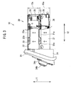
- FIG. 3 is a side view of the electronic equipment shown in FIG. 1;
- FIG. 4 is an exploded perspective view showing another embodiment of the electronic equipment according to the present invention;
- FIG. 5 is a front view of the electronic equipment shown in FIG. 4; and
- FIG. 6 is a side view of the electronic equipment shown in FIG. 4.
- The electronic equipment according to the present invention will now be described in detail in accordance with a preferred embodiment shown in the accompanying drawings.
- As shown in FIGS. 1 to 3, the present invention is exemplified in a preferred vehicle mountable
electronic equipment 10, as comprising adouble length case 20 having an overall length set at for example 2 DIN (Deutsche Institute Norm) size substantially twice as long as a predeterminedstandard length 10a (e.g., 1 DIN) in a predetermined direction shown by anarrow 11, afront panel 31 formed with a set ofholes double length case 20, adisplay circuit board 32 including a set ofvariable resistors double length case 20 and thefront panel 31, an LCD (Liquid Crystal Display)block 33 mounted on thedisplay circuit board 32 and positioned between thefront panel 31 and thedisplay circuit board 32, aknob 34a inserted in thehole 31a of thefront panel 31 and connected to thevariable resistor 32a of thedisplay circuit board 32, aknob 34b inserted in thehole 31b of thefront panel 31 and connected to thevariable resistor 32b of thedisplay circuit board 32, aknob 34c inserted in thehole 31c of thefront panel 31 and connected to thevariable resistor 32c of thedisplay circuit board 32, an IDC (In-Dash Changer) 35 housed in thedouble length case 20 for CD(Compact Disc) use, a plurality ofmain control boards double length case 20 and operative to control other AV (Audio Visual) systems provided in the vehicle not shown in the drawings and the IDC 35, aharness cable 38a having the IDC 35 and themain board 36 connected therethrough with each other, a set ofharness cables main boards harness cables display circuit 32 and themain board 36 connected with each other. - The
double length case 20 includes a metallicbottom cover case 21 accommodating themain control boards intermediate cover case 22 accommodating the IDC 35, a metallictop cover case 23 disposed on the opposite side of theintermediate cover case 22 as against thebottom cover case 21, ametallic front plate 24 disposed to be positioned between thebottom cover case 21 and thedisplay circuit board 32 on one side of thebottom cover case 21 in a direction in which thebottom cover case 21 and thefront panel 31 are arranged, a metallicrear plate 25 disposed on the other side of thebottom cover case 21 in the direction in which thebottom cover case 21 and thefront panel 31 are arranged, ametallic mounting member 26 for mounting the IDC 35 on therear plate 25, and ametallic heat sink 27 adapted to radiate therethrough heat from themain control boards - The
electronic equipment 10 further comprises a plurality ofmale screws 41 each screwed in thebottom cover case 21 and tightened to fixedly connect thebottom cover case 21 with themain control board 36, a plurality ofmale screws 42 each screwed in thebottom cover case 21 and tightened to fixedly connect thebottom cover case 21 with themain control board 37, a plurality ofmale screws 43 each screwed in thebottom cover case 21 and tightened to fixedly connect thebottom cover case 21 with theheat sink 27, a plurality ofmale screws 44 each screwed in a part of themain control board 36 and tightened to fixedly connect themain control board 36 with theheat sink 27, a plurality ofmale screws 45 each screwed in themounting member 26 and tightened to fixedly connect therear plate 25 with themounting member 26, a plurality ofmale screws 46 each screwed in thebottom cover case 21 and tightened to fixedly connect thebottom cover case 21 with therear plate 25, a plurality ofmale screws 47 each screwed in a part of themain control board 36 with tightened to fixedly connect themain control board 36 and therear plate 25, a plurality ofmale screws 48 each screwed in a part of the IDC 35 and tightened to fixedly connect themounting member 26 with the IDC 35, a plurality ofmale screws 49 each screwed in thebottom cover case 21 and tightened to fixedly connect thebottom cover case 21 with thefront plate 24, a plurality ofmale screws 50 each screwed in a part of themain control board 36 and tightened to fixedly connect thefront plate 24 with themain control board 36, a plurality ofmale screws 51 each screwed in a part of themain control board 37 and tightened to fixedly connect thefront plate 24 with themain control board 37, a plurality ofmale screws 52 each screwed in theintermediate cover case 22 and tightened to fixedly connect theintermediate cover case 22 with thefront plate 24, and a plurality ofmale screws 53 each screwed in thefront plate 24 and tightened to fixedly connect thefront plate 24 with thefront panel 31. - The
bottom cover case 21 is available for a part of a case 70 (See FIG. 4) of 1 DIN size that is a standard length case having in the predetermined direction shown by thearrow 11 anoverall length 10a. Thisbottom cover case 21 constitutes a common case member shorter in overall length in the predetermined direction than the standard length and available for a part of the standard length case. Thebottom cover case 21 also has left and right engagingportions 21a, i.e., a pair of common side engaging portions each held in fitting engagement with theintermediate cover case 22. Each of themain control boards bottom cover case 21. - The
intermediate cover case 22 constitutes an additional case member longer in overall length in the predetermined direction shown by thearrow 11 than thelength 10a and disposed on a predetermined side of thebottom cover case 21 in the predetermined direction shown by thearrow 11. Theintermediate cover case 22 also has left and right engagingportions 22a, i.e., a pair of additional side engaging portions each held in fitting engagement with the commonside engaging portions 21a of thebottom cover case 21, left and rightengaging portions 22b, i.e., a pair of cover engaging portions each held in fitting engagement with thetop cover case 23, and anelectromagnetic shield part 22c positioned between the IDC 35 and themain control boards side engaging portions 21a of thebottom cover case 21 and the additionalside engaging portions 22a of theintermediate cover case 22 are held in press-fit contact with each other in the direction shown by thearrow 13 different from both of the predetermined direction shown by thearrow 11 and a direction shown by anarrow 12. Further, theelectromagnetic shield part 22c of theintermediate cover case 22 is formed with apassage hole 22d having theharness cable 38a passed therethrough. The IDC 35 constitutes an additional side electronic part independent and separated from theintermediate cover case 22 and housed in theintermediate cover case 22. This IDC 35 is securely mounted on theintermediate cover case 22 by screws not shown in the drawings. - The
top cover case 23 of thedouble length case 20 has left and right engagingportions 23a each of which is a cover side engaging portion held in fitting engagement with any one of thecover engaging portions 22b of theintermediate cover case 22. The coverside engaging portions 23a of thetop cover case 23 and the commonside engaging portions 21a of thebottom cover case 21 are formed to be engageable with each other. - The
front plate 24 of thedouble length case 20 constitutes a connecting member for fixedly connecting thebottom case member 21 and theintermediate case member 22 to each other. Each of themale screws 49 constitutes a common side tightening member tightened to fixedly connect thefront plate 24 with thebottom cover case 21, while each of themale screws 52 constitutes an additional side tightening member tightened to fixedly connect theintermediate cover case 22 with thefront plate 24. - The
rear plate 25 of thedouble length case 20 also constitutes another connecting member for fixedly connecting thebottom case member 21 and theintermediate case member 22 to each other. Each of themale screws 46 constitutes a common side tightening member tightened to fixedly connect thebottom cover case 21 with therear plate 25, while each of themale screws 45 constitutes an additional side tightening member tightened to fixedly connect theintermediate cover case 22 with therear plate 25. - As aforementioned, the
bottom cover case 21 of thedouble length case 20 is available for a part of thecase 70 having theoverall length 10a in the direction shown by thearrow 11. - FIG. 4 shows a dash mount
electronic equipment 60 and thecase 70. - As shown in FIGS. 4-6, the
electronic equipment 60 comprises theabove case 70 of 1 DIN size having anoverall length 10a in the direction shown in thearrow 11, afront panel 81 formed with a set ofholes case 70, adisplay circuit board 82 including a set ofvariable resistors case 70 and thefront panel 81 and mounted on thefront panel 81, anLCD block 83 mounted on thedisplay circuit board 82 and positioned between thefront panel 81 and thedisplay circuit board 82, aknob 84a inserted in thehole 81a of thefront panel 81 and connected to thevariable resistor 82a of thedisplay circuit board 82, aknob 84b inserted in thehole 81b of thefront panel 81 and connected to thevariable resistor 82b of thedisplay circuit board 82, aknob 84c inserted in thehole 81c of thefront panel 81 and connected to thevariable resistor 82c of thedisplay circuit board 82, a plurality ofmain control boards case 70 and operative to control other AV (Audio Visual) systems provided in the vehicle not shown in the drawings, a set ofharness cables main boards harness cables display circuit 82 and themain control board 36 connected with each other. - The
case 70 includes the above metallicbottom cover case 21 having themain control boards top cover case 23, ametallic front plate 74 disposed to be positioned between thebottom cover case 21 and thedisplay circuit board 82 on one side of thecase 70 in the direction shown by thearrow 12 in which thebottom cover case 21 and thefront panel 81 are arranged, a metallicrear plate 25 disposed on the other side of thecase 70, i.e., the opposite side of thecase 70 as against thefront plate 74 in the direction shown by thearrow 12, and ametallic heat sink 27 adapted to radiate therethrough heat from themain control boards side engaging portions 21a of thebottom cover case 21 and the coverside engaging portions 23a of thetop cover case 23 are held in press-fit contact with each other in the direction shown by thearrow 13 perpendicular to the predetermined direction shown by thearrow 11 and the direction shown by anarrow 12. - The electronic equipment 60 further comprises a plurality of male screws 91 each screwed in the bottom cover case 21 and tightened to fixedly connect the bottom cover case 21 with the main control board 36, a plurality of male screws 92 each screwed in the bottom cover case 21 and tightened to fixedly connect the bottom cover case 21 with the main control board 37, a plurality of male screws 93 each screwed in the bottom cover case 21 and tightened to fixedly connect the bottom cover case 21 with the heat sink 27, a plurality of male screws 94 each screwed in a part of the main control board 36 and tightened to fixedly connect the main control board 36 with the heat sink 27, a plurality of male screws 95 each screwed in the bottom cover case 21 and tightened to fixedly connect the bottom cover case 21 with the rear plate 25, a plurality of male screws 96 each screwed in a part of the main control board 36 and tightened to fixedly connect the rear plate 25 and the main control board 36, a plurality of male screws 97 each screwed in the bottom cover case 21 and tightened to fixedly connect the bottom cover case 21 with the front plate 74, a plurality of male screws 98 each screwed in a part of the main control board 36 and tightened to fixedly connect the front plate 74 with the main control board 36, a plurality of male screws 99 each screwed in a part of the main control board 37 and tightened to fixedly connect the front plate 74 with the main control board 37, and a plurality of male screws 100 each screwed in the front plate 74 and tightened to fixedly connect the front plate 74 with the front panel 81.
- Hereinafter, the process of assembling the above
electronic equipment 10 shown in FIG. 1 is described. - Firstly, the
main control board 36 is securely mounted on thebottom cover case 21 by themale screws 41 while themain control board 37 is securely mounted on thebottom cover case 21 by the male screws 42. Theharness cables main control board bottom cover case 21. - Then, the
heat sink 27 is fixedly connected by the plurality ofmale screws bottom cover case 21 and themain control board 36 securely mounted on thebottom cover case 21. Theharness cable 38a is then led through thepassage hole 22d of theintermediate cover case 22, while the engagingportions 22a of theintermediate cover case 22 are brought into fitting engagement with the engagingportions 21a of thebottom cover case 21 to securely mount theintermediate cover case 22 on thebottom cover case 21. - The
harness cable 38a led through thepassage hole 22d of theintermediate cover case 22 is then connected to theIDC 35, while theIDC 35 is securely mounted on theintermediate cover case 22 by male screws not shown in the drawings. - The engaging
portions 23a of thetop cover case 23 are then brought into fitting engagement with the engagingportions 22b of theintermediate cover case 22 to securely mount thetop cover case 23 on theintermediate cover case 22. Therear plate 25 and the mountingmember 26, preliminarily fixedly connected to each other by themale screws 45, are then fixedly connected to thebottom cover case 21, themain control board 36 and theIDC 35 by themale screws front plate 24 is fixedly connected to thebottom cover case 21, themain control board 36, themain control board 37 and theintermediate cover case 22 by themale screws - Then, the
display circuit board 32, theLCD block 33 and theknob front panel 31, while theharness cables display circuit board 32 attached to thefront panel 31. Finally, thefront panel 31 is securely mounted on thefront plate 24 by the male screws 53. Theelectronic equipment 10 is thus assembled. - Next, the process of assembling the
electronic equipment 60 shown in FIG. 4 is described. - Firstly, the
main control board 36 is securely mounted on thebottom cover case 21 by themale screws 91 while themain control board 37 is securely mounted on thebottom cover case 21 by the male screws 92. Theharness cables main control board bottom cover case 21. - Then, the
heat sink 27 is fixedly connected to each of thebottom cover case 21 and themain control board 36 securely mounted on thebottom cover case 21. The engagingportions 23a of thetop cover case 23 are then brought into fitting engagement with the engagingportions 21a of thebottom cover case 21 to securely mount thetop cover case 23 on thebottom cover case 21. - The
rear plate 25 is then fixedly connected to thebottom cover case 21 and themain control board 36 respectively by themale screws front plate 74 is fixedly connected to thebottom cover case 21, themain control board 36 and themain control board 37 by themale screws - Then, the
display circuit board 82, theLCD block 83 and theknob front panel 81, while theharness cables display circuit board 82 attached to thefront panel 81. Finally, thefront panel 81 is securely mounted on thefront plate 74 by themale screws 100. Theelectronic equipment 60 is thus assembled. - According to the
electronic equipment 10 shown in FIG 3, thedouble length case 20 of 2 DIN size is mainly constituted by thebottom cover case 21, thetop cover case 23, therear plate 25 and theheat sink 27 which are also available for the corresponding parts of thecase 70 of 1 DIN size shown in FIG 6. It is therefore possible to reduce the steps of designing cases and the production cost of parts of the cases and their dies in comparison with a case constituted by exclusive parts similar to thebottom cover case 21, thetop cover case 23, therear plate 25 and theheat sink 27 and unavailable for any one of the cases different in size from thedouble length case 20. - The above
electronic equipment 10, however, may be modified by changing one of thetop cover case 23, therear plate 25 and theheat sink 27 not to be used for thecase 70 of 1 DIN size but to be exclusively used for thedouble length case 20 of 2 DIN size. - The
main control boards electronic equipment 10 as well as those of theelectronic equipment 60, thereby making it possible to reduce the steps of designing control boards and the production cost of the control boards in comparison with exclusive control boards similar to themain control boards main control boards electronic equipment 10 may be replaced an exclusive main control board unavailable for theelectronic equipment 60. - According to the present embodiment, the
bottom cover case 21 and theintermediate cover case 22 are prevented from separating from each other by means of the engagingportions arrow 13. This fitting engagement including the press-fit contact of thebottom cover case 21 and theintermediate cover case 22 makes it possible to reduce connecting steps of thebottom cover case 21 and theintermediate cover case 22 and the number of screws and other tightening parts of thecase 20 as compared with engagement by which thebottom cover case 21 and theintermediate cover case 22 are not prevented from separating from each other. In theelectronic equipment 10, the engagingportions arrow 11. - Further, according to the present
electronic equipment 10, thefront plate 24 and therear plate 25 are respectively disposed on one side and the other side of thebottom cover case 21 in the direction shown by thearrow 12. Theseplates double length case 20 in a direction perpendicular to the direction shown by thearrow 12, even in the case that there is a limit to the overall length of thedouble length case 20 in the direction shown by thearrow 13, in comparison with other connecting members disposed on one and/or the other side in the direction shown by thearrow 13. The electronic equipment according to the present invention, however, may comprise a connecting member on one or/and the other side in the direction shown by thearrow 13. - In the present
electronic equipment 10, theIDC 35, i.e., the additional side electronic part housed in and independent from theintermediate cover case 22 is allowed to be separated from theintermediate cover case 22. In the case that theIDC 35 has a certain connecting portion facing to theintermediate cover case 22, the connecting portion can be connected with theharness cable 38a. It is therefore possible to facilitate to design theIDC 35 in comparison with an additional side electronic part inseparably or partly integrally mounted on theintermediate cover plate 22, i.e., the additional case member. The electronic equipment according to the present invention, however, may comprise an additional side electronic part inseparably housed in the additional case member, such as for example an additional side electronic part having a casing member forming part of the additional case member. - Furthermore, the
electromagnetic shield part 22c of theintermediate cover case 22 formed with thepassage hole 22d allows theharness cable 38a to pass therethrough to connect themain control board 36, i.e., the common side electronic part and theIDC 35. Theintermediate cover case 22 therefore makes it possible to reduce and shorten the length of theharness cable 38a between themain control board 36 and theIDC 35 as compared with a common side case member having no passing hole allowing theharness cable 38a to pass therethrough to connect themain control board 36 and theIDC 35. - In this
electronic equipment 10, themain control boards IDC 35, or/and, theIDC 35 is shielded from an electromagnetic wave radiated from either themain control board 36 or themain control board 37. This enables to prevent each of themain control boards electronic equipment 10 may comprise an additional case member having no electromagnetic shield portion between themain control boards IDC 35. - The
electronic equipment 10 is assembled in a similar manner to theelectronic equipment 60 by an assembling system. The assembling system can therefore be used for common use and shared by theelectronic equipment 10 and theelectronic equipment 60. It is therefore possible for the assembling system to produce each of theelectronic equipments electronic equipment 10 and theelectronic equipment 60. - The above
electronic equipment 10 may be modified by replacing theIDC 35 by another electronic part different in type from theIDC 35, although theelectronic equipment 10 comprises theIDC 35 as an additional side electronic part. The additional side electronic part of theelectronic equipment 10 may be constituted by a deck such as for example a cassette tape deck, MD (Mini Disc) deck or the like, or an electronic circuit board. Similarly, the aboveelectronic equipment 10 may be modified by replacing themain control board main control board - Although the above
electronic equipment 10 is constituted by thebottom cover case 21, thetop cover case 23 and theintermediate cover case 22 disposed on the side of thebottom cover case 21 to be positioned between thebottom cover case 21 and thetop cover case 23, theelectronic equipment 10 may be modified by changing the disposition of the additional side case member such as theintermediate cover case 22 to be on the opposite of thebottom cover case 21 as against thetop cover case 23. - As will be seen from the foregoing description, the electronic equipment according to the present invention comprises a common case member available for each of the cases different in size from one another. The present invention is therefore useful to various types of electronic equipments each comprising a case.
Claims (7)
- An electronic equipment, comprising a double length case having an overall length substantially twice as long as a predetermined standard length in a predetermined direction, in which said double length case includes a common case member shorter in overall length in said predetermined direction than said standard length and available for a part of a standard length case having in said predetermined direction an overall length identical to said standard length, and an additional case member longer in overall length in said predetermined direction than said standard length case and disposed on a predetermined side of said common case member, said common case member having a common side engaging portion held in fitting engagement with said additional case member, and said additional case member having an additional side engaging portion held in fitting engagement with said common side engaging portion of said common case member.
- An electronic equipment as set forth in claim 1, in which said common side engaging portion and said additional side engaging portion are held in press-fit contact with each other in a direction different from said predetermined direction.
- An electronic equipment as set forth in claim 1, further comprising: a front panel disposed on the front side of said double length case; a connecting member for fixedly connecting said common case member and said additional case member to each other; a common side tightening member operable to tighten and fixedly connect said connecting member with said common case member; and an additional side tightening member operable to tighten and fixedly connect said connecting member with said additional case member, said connecting member being disposed on one or the other side in a direction in which said common case member and said front panel are arranged.
- An electronic equipment as set forth in claim 1, further comprising: a common side electronic part housed in said common case member; an additional side electronic part housed in said additional case member to be independent from said additional case member; and a harness cable having said common side electronic part and said additional side electronic part connected to each other.
- An electronic equipment as set forth in claim 4, in which said additional case member is formed with a passage hole having said harness cable passed therethrough to connect said common side electronic part and said additional side electronic part.
- An electronic equipment as set forth in claim 1, further comprising: a common side electronic part housed in said common case member; and an additional side electronic part housed in said additional case member, said additional case member having an electromagnetic shield part positioned between said common side electronic part and said additional side electronic part, and operative to shield one of said common side electronic part and said additional side electronic part from an electromagnetic wave radiated from the other of said common side electronic part and said additional side electronic part.
- An electronic equipment as set forth in claim 4, in which said double length case includes a cover member disposed on the opposite side of said additional case member as against said common case member, said additional case member having for covering use a cover engaging portion held in fitting engagement with said cover member, and said cover member having a cover side engaging portion held in fitting engagement with said engaging portion of said additional case member, said cover side engaging portion and said common side engaging portion being engageable with each other.
Applications Claiming Priority (2)
| Application Number | Priority Date | Filing Date | Title |
|---|---|---|---|
| JP2003174999A JP4276479B2 (en) | 2003-06-19 | 2003-06-19 | Automotive electronics |
| PCT/JP2004/007590 WO2004113128A1 (en) | 2003-06-19 | 2004-05-26 | Electronic equipment |
Publications (2)
| Publication Number | Publication Date |
|---|---|
| EP1634775A1 true EP1634775A1 (en) | 2006-03-15 |
| EP1634775A4 EP1634775A4 (en) | 2010-11-17 |
Family
ID=33534806
Family Applications (1)
| Application Number | Title | Priority Date | Filing Date |
|---|---|---|---|
| EP04734910A Withdrawn EP1634775A4 (en) | 2003-06-19 | 2004-05-26 | ELECTRONIC EQUIPMENT |
Country Status (5)
| Country | Link |
|---|---|
| US (1) | US7601911B2 (en) |
| EP (1) | EP1634775A4 (en) |
| JP (1) | JP4276479B2 (en) |
| CN (1) | CN100364811C (en) |
| WO (1) | WO2004113128A1 (en) |
Families Citing this family (10)
| Publication number | Priority date | Publication date | Assignee | Title |
|---|---|---|---|---|
| US7659988B2 (en) * | 2006-06-30 | 2010-02-09 | Asml Netherlands B.V. | Apparatus for angular-resolved spectroscopic lithography characterization and device manufacturing method |
| US9237685B2 (en) | 2006-08-18 | 2016-01-12 | Delphi Technologies, Inc. | Lightweight audio system for automotive applications and method |
| US7733659B2 (en) | 2006-08-18 | 2010-06-08 | Delphi Technologies, Inc. | Lightweight audio system for automotive applications and method |
| WO2010099415A1 (en) | 2009-02-27 | 2010-09-02 | Delphi Technologies, Inc. | Lightweight audio system for automotive appalications and method |
| US8441801B2 (en) * | 2010-04-27 | 2013-05-14 | Electrolux Home Products, Inc. | Flexible mount system |
| US9079546B2 (en) * | 2010-12-14 | 2015-07-14 | Mitsubishi Electric Corporation | Vehicle-mounted information apparatus |
| CN104509225B (en) * | 2012-08-03 | 2016-03-30 | 三菱电机株式会社 | Bracket assembly structure |
| DE102019133746A1 (en) * | 2019-12-10 | 2021-06-10 | Schenck Process Europe Gmbh | Modular built-in device and processing device with built-in device |
| US11372458B2 (en) * | 2020-03-12 | 2022-06-28 | Adlink Technology Inc. | Structure of case assembly |
| JP7697336B2 (en) * | 2021-09-27 | 2025-06-24 | 株式会社Jvcケンウッド | electronic equipment |
Family Cites Families (11)
| Publication number | Priority date | Publication date | Assignee | Title |
|---|---|---|---|---|
| JPS5860977A (en) | 1981-10-03 | 1983-04-11 | Furointo Sangyo Kk | Desiccant cassette |
| JPS5860977U (en) * | 1981-10-20 | 1983-04-25 | 日本電気株式会社 | Electronic circuit storage device |
| JP3023013B2 (en) * | 1991-07-08 | 2000-03-21 | クラリオン株式会社 | Case assembly structure |
| JPH07156720A (en) * | 1993-12-08 | 1995-06-20 | Nippondenso Co Ltd | Casing structure for electronic equipment |
| JPH10154890A (en) * | 1996-11-22 | 1998-06-09 | Mitsumi Electric Co Ltd | Assembly structure of multiple shield cases |
| JPH11268594A (en) * | 1998-03-24 | 1999-10-05 | Fujitsu Ten Ltd | Decorative frame |
| US6157715A (en) * | 1998-08-28 | 2000-12-05 | Lucent Technologies, Inc. | Modular layered network interface unit |
| JP3785276B2 (en) * | 1998-09-10 | 2006-06-14 | 矢崎総業株式会社 | Electrical junction box |
| US6353697B1 (en) * | 1999-07-30 | 2002-03-05 | Lucent Technologies, Inc. | Modular layered splice holder |
| US6359218B1 (en) * | 2000-04-04 | 2002-03-19 | Sun Microsystems, Inc. | Modular and expandable enclosure for electronic equipment |
| US6321925B1 (en) * | 2001-01-23 | 2001-11-27 | Avaya Technology Corp. | Multiple layer hinged enclosure |
-
2003
- 2003-06-19 JP JP2003174999A patent/JP4276479B2/en not_active Expired - Lifetime
-
2004
- 2004-05-26 WO PCT/JP2004/007590 patent/WO2004113128A1/en not_active Ceased
- 2004-05-26 US US10/560,538 patent/US7601911B2/en not_active Expired - Fee Related
- 2004-05-26 CN CNB2004800172248A patent/CN100364811C/en not_active Expired - Fee Related
- 2004-05-26 EP EP04734910A patent/EP1634775A4/en not_active Withdrawn
Also Published As
| Publication number | Publication date |
|---|---|
| CN100364811C (en) | 2008-01-30 |
| US20060126274A1 (en) | 2006-06-15 |
| US7601911B2 (en) | 2009-10-13 |
| JP2005012014A (en) | 2005-01-13 |
| WO2004113128A1 (en) | 2004-12-29 |
| CN1809481A (en) | 2006-07-26 |
| JP4276479B2 (en) | 2009-06-10 |
| EP1634775A4 (en) | 2010-11-17 |
Similar Documents
| Publication | Publication Date | Title |
|---|---|---|
| EP2544375B1 (en) | Lightweight audio system for automotive applications and method | |
| US6388881B2 (en) | Vehicle center cluster assembling structure with electrical connection | |
| US7683254B2 (en) | Electrical junction box incorporating an electronic component and electrical connection unit having thereof | |
| EP0782216B1 (en) | An electrical connection box, a connection construction, a bus bar fixing construction and a connection terminal | |
| EP1634775A1 (en) | Electronic equipment | |
| EP3068207B1 (en) | Lightweight electrical assembly with enhanced electromagnetic shielding | |
| US7006357B2 (en) | Shielding case for electronic devices | |
| US20130021743A1 (en) | Expansion card mounting assembly | |
| US7626830B2 (en) | Bracket assembly for expansion cards | |
| GB2346858A (en) | An integrated instrument cluster and fuse block | |
| US5543581A (en) | Branching connection box for electrical circuits | |
| JPH11261254A (en) | PCB mounting structure | |
| US20090161324A1 (en) | Shielding case, wiring board and electronic module | |
| JP2009140690A (en) | Electronic component junction box laminate and electronic component built-in unit | |
| US6178095B1 (en) | Structure for fixing an element to a printed wiring board, and electronic equipment having the structure | |
| US20220217854A1 (en) | Sealed and unsealed electronic assemblies using common design | |
| US6106307A (en) | Pluggable I/O breakout connector module | |
| US7782631B2 (en) | Flat panel displays | |
| JP6573789B2 (en) | Electronic component unit manufacturing method and electronic component unit | |
| US20240195095A1 (en) | Electronic device | |
| JPH08316650A (en) | Case structure for computer mounted on car | |
| JP4327033B2 (en) | Electronic control unit housing structure | |
| WO2022150558A1 (en) | Sealed and unsealed electronic assemblies using common design | |
| JP2001119174A (en) | Terminal base | |
| JP2002314261A (en) | Electronic equipment to be mounted on car |
Legal Events
| Date | Code | Title | Description |
|---|---|---|---|
| PUAI | Public reference made under article 153(3) epc to a published international application that has entered the european phase |
Free format text: ORIGINAL CODE: 0009012 |
|
| 17P | Request for examination filed |
Effective date: 20051214 |
|
| AK | Designated contracting states |
Kind code of ref document: A1 Designated state(s): DE FR GB |
|
| DAX | Request for extension of the european patent (deleted) | ||
| RBV | Designated contracting states (corrected) |
Designated state(s): DE FR GB |
|
| RAP1 | Party data changed (applicant data changed or rights of an application transferred) |
Owner name: PANASONIC CORPORATION |
|
| A4 | Supplementary search report drawn up and despatched |
Effective date: 20101014 |
|
| RIC1 | Information provided on ipc code assigned before grant |
Ipc: B60R 11/02 20060101ALI20101008BHEP Ipc: H04B 1/08 20060101AFI20101008BHEP Ipc: H05K 5/00 20060101ALI20101008BHEP |
|
| STAA | Information on the status of an ep patent application or granted ep patent |
Free format text: STATUS: THE APPLICATION IS DEEMED TO BE WITHDRAWN |
|
| 18D | Application deemed to be withdrawn |
Effective date: 20110429 |