EP1634758A1 - Transmission unit particularly for driving the screw feeders and auxiliary user devices of mixing trucks - Google Patents
Transmission unit particularly for driving the screw feeders and auxiliary user devices of mixing trucks Download PDFInfo
- Publication number
- EP1634758A1 EP1634758A1 EP05019303A EP05019303A EP1634758A1 EP 1634758 A1 EP1634758 A1 EP 1634758A1 EP 05019303 A EP05019303 A EP 05019303A EP 05019303 A EP05019303 A EP 05019303A EP 1634758 A1 EP1634758 A1 EP 1634758A1
- Authority
- EP
- European Patent Office
- Prior art keywords
- screw feeders
- unit according
- friction clutch
- auxiliary
- piston
- Prior art date
- Legal status (The legal status is an assumption and is not a legal conclusion. Google has not performed a legal analysis and makes no representation as to the accuracy of the status listed.)
- Granted
Links
Images


Classifications
-
- A—HUMAN NECESSITIES
- A01—AGRICULTURE; FORESTRY; ANIMAL HUSBANDRY; HUNTING; TRAPPING; FISHING
- A01K—ANIMAL HUSBANDRY; AVICULTURE; APICULTURE; PISCICULTURE; FISHING; REARING OR BREEDING ANIMALS, NOT OTHERWISE PROVIDED FOR; NEW BREEDS OF ANIMALS
- A01K5/00—Feeding devices for stock or game ; Feeding wagons; Feeding stacks
- A01K5/001—Fodder distributors with mixer or shredder
-
- B—PERFORMING OPERATIONS; TRANSPORTING
- B60—VEHICLES IN GENERAL
- B60K—ARRANGEMENT OR MOUNTING OF PROPULSION UNITS OR OF TRANSMISSIONS IN VEHICLES; ARRANGEMENT OR MOUNTING OF PLURAL DIVERSE PRIME-MOVERS IN VEHICLES; AUXILIARY DRIVES FOR VEHICLES; INSTRUMENTATION OR DASHBOARDS FOR VEHICLES; ARRANGEMENTS IN CONNECTION WITH COOLING, AIR INTAKE, GAS EXHAUST OR FUEL SUPPLY OF PROPULSION UNITS IN VEHICLES
- B60K17/00—Arrangement or mounting of transmissions in vehicles
- B60K17/28—Arrangement or mounting of transmissions in vehicles characterised by arrangement, location, or type of power take-off
-
- B—PERFORMING OPERATIONS; TRANSPORTING
- B60—VEHICLES IN GENERAL
- B60Y—INDEXING SCHEME RELATING TO ASPECTS CROSS-CUTTING VEHICLE TECHNOLOGY
- B60Y2200/00—Type of vehicle
- B60Y2200/20—Off-Road Vehicles
- B60Y2200/22—Agricultural vehicles
-
- F—MECHANICAL ENGINEERING; LIGHTING; HEATING; WEAPONS; BLASTING
- F16—ENGINEERING ELEMENTS AND UNITS; GENERAL MEASURES FOR PRODUCING AND MAINTAINING EFFECTIVE FUNCTIONING OF MACHINES OR INSTALLATIONS; THERMAL INSULATION IN GENERAL
- F16H—GEARING
- F16H3/00—Toothed gearings for conveying rotary motion with variable gear ratio or for reversing rotary motion
- F16H3/44—Toothed gearings for conveying rotary motion with variable gear ratio or for reversing rotary motion using gears having orbital motion
- F16H3/46—Gearings having only two central gears, connected by orbital gears
- F16H3/60—Gearings for reversal only
-
- Y—GENERAL TAGGING OF NEW TECHNOLOGICAL DEVELOPMENTS; GENERAL TAGGING OF CROSS-SECTIONAL TECHNOLOGIES SPANNING OVER SEVERAL SECTIONS OF THE IPC; TECHNICAL SUBJECTS COVERED BY FORMER USPC CROSS-REFERENCE ART COLLECTIONS [XRACs] AND DIGESTS
- Y10—TECHNICAL SUBJECTS COVERED BY FORMER USPC
- Y10T—TECHNICAL SUBJECTS COVERED BY FORMER US CLASSIFICATION
- Y10T74/00—Machine element or mechanism
- Y10T74/19—Gearing
- Y10T74/19172—Reversal of direction of power flow changes power transmission to alternate path
Definitions
- the screw feeders can be provided with blades which shred the forage in addition to mixing it.
- desiling and mixing trucks are known in particular which in addition to mixing and optionally shredding the forage also remove it from storage silos and load it into the body of the truck (desiling) by means of a loading mill.
- reduction units are known which are the subject of Italian industrial invention patent application No. MI2001A00436 and of the corresponding European patent EP1,236,606 in the name of the same Applicant and are substantially constituted by an off-center gearbox, which can be associated with the power take-off of a tractor and forms couplings for connection to auxiliary user devices, by a reduction unit which is functionally collected to the off-center gearbox, and by a friction clutch, which is interposed between the off-center gearbox and the reduction unit and allows to interrupt the transmission of motion to the screw feeders but not to the auxiliary user devices.
- this operation entails the need to provide in the reduction unit an auxiliary input, which is constructively complicated and entails substantial bulk, which can interfere with the devices for protecting the cardan shaft or with the auxiliary user devices connected to the off-center gearbox; moreover, such user devices must be of the bidirectional type.
- the aim of the present invention is to eliminate the drawbacks mentioned above, by providing a transmission unit particularly for driving screw feeders and auxiliary user devices of mixing trucks which allows to reverse the direction of rotation of the screw feeders simply and rapidly, minimizing, if not eliminating, the need for intervention of assigned operators.
- a further object of the present invention is to provide a transmission unit that is constructively and structurally simple, has compact dimensions and can be easily installed on known trucks and connected to the power take-off of known tractors without requiring any modification thereof.
- Not last object of the present invention is to provide a transmission unit having a structure that is simple, relatively easy to provide in practice, safe in use, effective in operation, and has a relatively low cost.
- the present transmission unit particularly for driving screw feeders and auxiliary user devices of mixing trucks, comprising: an off-center distribution device, which can be associated with an external power take-off and forms couplings for the connection of auxiliary user devices; a reduction unit, which is functionally connected to said off-center distribution device and can be associated with the screw feeders of a mixing truck; and a main friction clutch device, which is interposed between said off-center distribution device and said reduction unit, characterized in that it comprises a device for reversing the direction of rotation of said screw feeders and an auxiliary friction clutch device for said reversing device.
- the auxiliary friction clutch device 6 is in the disengaged configuration when the main friction clutch device 4 is in the engaged configuration; the main friction clutch device 4 is in the disengaged configuration when the auxiliary friction clutch device 6 is in the engaged configuration, and there is a neutral configuration in which both friction clutch devices, the main one 4 and the auxiliary one 6, are disengaged.
- the off-center distribution device 2 comprises a containment case 7, which rotatably supports an input shaft 8, which can be connected to an external power take-off of a farming tractor and on which an input gear 9 is keyed.
- the input gear 9 meshes with a first driven gear 10, which is keyed on a driven shaft 11 supported rotatably by the case 7, and with a second driven gear 12, which is supported rotatably by the case 7 and has internal slotted profiles 13 for connection to auxiliary user devices U, such as for example the pumps used for the hydraulic actuation of the elements of the unit 1 or of other services of the truck.
- auxiliary user devices U such as for example the pumps used for the hydraulic actuation of the elements of the unit 1 or of other services of the truck.
- the reduction unit 3 is constituted by a first epicyclic reduction unit with one or more stages, which is shown only partially since it is of a conventionally known type; the shaft of its input sun gear has been designated by the reference numeral 14.
- the reversing device 5 comprises: a sun gear 24, which is formed on the driven shaft 11 of the off-center distribution device 2; at least one planetary gear 25, which is supported rotatably by a gear carrier 26, which is mounted rotatably on the driven shaft 11; and a ring gear 27 with internal teeth, which rotates rigidly with the clutch bell 15 and meshes with the planetary gears 25.
- Second fluid-operated actuation means 30 are provided for the actuation of the auxiliary friction clutch device 6.
- the transmission unit 1 comprises a braking device 31, (negative safety device, which locks the screw feeders if no motion is occurring), which acts on the clutch bell 15 or on the shaft of the input sun gear 14 of the reduction unit 3 and is suitable to block the actuation of the screw feeders with both friction clutch devices, the main one 4 and the auxiliary one 6, in the disengaged configuration.
- a braking device 31 negative safety device, which locks the screw feeders if no motion is occurring
- the braking device 31 is constituted by a brake disc 32, which rotates rigidly with the outer lateral surface of the clutch bell 15, and by at least one abutment surface 33, which is rotationally fixed and is formed within a containment body 34, which is rigidly coupled to the case 7 and to the casing 35 of the reduction unit 3.
- Means for the pressure clamping of the brake disc 32 against the abutment surfaces 33 and fluid-operated means for deactivating said clamping means are further provided and are conveniently integrated with respect to the second fluid-operated actuation means 30.
- the second fluid-operated actuation means 30 are constituted by a second piston 36 (which is annular and of the single-acting type), which is locked rotationally by means of a pin, not shown, and cooperates with an auxiliary piston 37, which is interposed between it and the containment body 34, and second elastic contrast means, which are constituted by second springs 38 interposed between the second piston 36 and a second complementary disk 39, which is rigidly coupled to the case 7.
- the oil that enters the second chamber 40 (the auxiliary chamber 41 being connected to the discharge) pushes the second piston 36 toward the auxiliary friction clutch device 6, closing it and simultaneously deactivating the braking device 31 (the auxiliary piston 37 remaining in abutment against the containment body 34).
- the hydraulic circuit C comprises a second channel 46 and a third channel 47, which is a branch of the first connection channel 44, for connecting respectively the second chamber 40 and the auxiliary chamber 41 to the source 45.
- the first criterion consists in detecting (by means of the torque sensor 61) the torque (torsional moment) transmitted to the screw feeders and in comparing the detected value with a maximum reference value, overload being determined by the positive difference of the detected value with respect to the maximum reference value.
- the second criterion consists in detecting the difference between the rotation rate in input and in output (by means of the first and second detectors 59 and 60) from the screw feeders, in comparing said difference with a maximum reference threshold, overload being determined by the positive difference between the detected difference and the maximum reference threshold.
- the transmission unit according to the invention in fact allows to reverse the motion of the screw feeders of a mixing truck simply and rapidly without requiring any human intervention and without having to disconnect the external power take-off or reverse the travel of the truck and keeping unchanged the actuation and functionality of the auxiliary user devices, particularly of the pump that feeds the hydraulic circuit and of all the detection and measurement devices.
Landscapes
- Life Sciences & Earth Sciences (AREA)
- Environmental Sciences (AREA)
- Birds (AREA)
- Animal Husbandry (AREA)
- Biodiversity & Conservation Biology (AREA)
- Hydraulic Clutches, Magnetic Clutches, Fluid Clutches, And Fluid Joints (AREA)
- Screw Conveyors (AREA)
- Feeding And Watering For Cattle Raising And Animal Husbandry (AREA)
- Gear Transmission (AREA)
- Threshing Machine Elements (AREA)
- Arrangement Or Mounting Of Control Devices For Change-Speed Gearing (AREA)
Abstract
Description
- The present invention relates to a transmission unit particularly for driving the screw feeders and auxiliary user devices of mixing trucks.
- As is known, mixing trucks are machines used in the agricultural field, particularly in animal farms, for mixing forage and optionally reducing its dimensions and volume.
- These trucks are constituted substantially by a body inside which there are screw feeders, generally two contrarotating screw feeders, which are turned by a transmission unit, which draws its motion from a power take-off of a farming tractor by means of a cardan shaft or the like.
- The screw feeders can be provided with blades which shred the forage in addition to mixing it.
- Among mixing trucks, desiling and mixing trucks are known in particular which in addition to mixing and optionally shredding the forage also remove it from storage silos and load it into the body of the truck (desiling) by means of a loading mill.
- Desiling occurs generally while the screw feeders are moving; there is in fact a permanent functional connection, so that the actuation of the loading mill entails the automatic actuation of the screw feeders.
- In order to separate the actuation of the screw feeders from the actuation of the loading mill or of any other auxiliary user devices, reduction units are known which are the subject of Italian industrial invention patent application No. MI2001A00436 and of the corresponding European patent EP1,236,606 in the name of the same Applicant and are substantially constituted by an off-center gearbox, which can be associated with the power take-off of a tractor and forms couplings for connection to auxiliary user devices, by a reduction unit which is functionally collected to the off-center gearbox, and by a friction clutch, which is interposed between the off-center gearbox and the reduction unit and allows to interrupt the transmission of motion to the screw feeders but not to the auxiliary user devices.
- However, these known reduction units are susceptible of further improvements.
- In particular, it is noted that if the truck jams as a consequence of an excessive accumulation of forage between the screw feeders which blocks them, it is necessary to stop its operation and reverse the direction of rotation of the screw feeders in order to remove the forage that is stuck between them.
- In known mixing trucks, such unblocking operation is performed by disconnecting manually the power take-off from the main input shaft of the reduction unit and connecting it to a shaft that is adjacent thereto, so as to reverse the direction of rotation in output from the reduction unit.
- This operation entails performing particularly time-consuming and labor-intensive maneuvers, which slow the preparation of the fodder and by being performed manually endanger the safety of the operators.
- Further, this operation entails the need to provide in the reduction unit an auxiliary input, which is constructively complicated and entails substantial bulk, which can interfere with the devices for protecting the cardan shaft or with the auxiliary user devices connected to the off-center gearbox; moreover, such user devices must be of the bidirectional type.
- As an alternative, if the tractor is provided with a power take-off that can be synchronized with the reverse gear, it is possible to reverse the direction of rotation of the screw feeders by driving the truck backward, a maneuver which in itself is not advisable for safety reasons.
- In reduction units provided with a friction clutch, the rotation rate generated in reverse gear and transmitted to the auxiliary user devices, particularly to the pump of the hydraulic circuit that drives the coupling of the clutch device, can be disadvantageously lower than the rotation rate required to generate the necessary pressure for the coupling of the device; accordingly, the screw feeders remain motionless and the truck remains jammed. Finally, it is noted that the operations for detecting the jamming of the truck and the release operations are performed and controlled manually by the assigned operators; therefore, they are generally performed late and/or for excessively long times, subjecting the screw feeders and the rotary motion transmission elements to overloads and stresses which, over time, compromise their integrity and correct operation.
- The aim of the present invention is to eliminate the drawbacks mentioned above, by providing a transmission unit particularly for driving screw feeders and auxiliary user devices of mixing trucks which allows to reverse the direction of rotation of the screw feeders simply and rapidly, minimizing, if not eliminating, the need for intervention of assigned operators.
- Within this aim, an object of the present invention is to provide a transmission unit which allows to reverse the direction of rotation of the screw feeders but not the direction of rotation of the auxiliary user devices, eliminating the use of bidirectional user devices, and to ensure in input to such user devices a power (rotation rate) that is sufficient for their correct operation.
- Another object of the present invention is to provide a transmission unit that ensures the safety of the assigned operators.
- A further object of the present invention is to provide a transmission unit that is constructively and structurally simple, has compact dimensions and can be easily installed on known trucks and connected to the power take-off of known tractors without requiring any modification thereof.
- Finally, another object of the present invention is to provide a transmission unit that allows to detect automatically any jamming of the trucks and to control the time for which the direction of rotation of the screw feeders is reversed, limiting the overloads that act on the transmission elements.
- Not last object of the present invention is to provide a transmission unit having a structure that is simple, relatively easy to provide in practice, safe in use, effective in operation, and has a relatively low cost.
- This aim and these and other objects that will become better apparent hereinafter are achieved by the present transmission unit particularly for driving screw feeders and auxiliary user devices of mixing trucks, comprising: an off-center distribution device, which can be associated with an external power take-off and forms couplings for the connection of auxiliary user devices; a reduction unit, which is functionally connected to said off-center distribution device and can be associated with the screw feeders of a mixing truck; and a main friction clutch device, which is interposed between said off-center distribution device and said reduction unit, characterized in that it comprises a device for reversing the direction of rotation of said screw feeders and an auxiliary friction clutch device for said reversing device.
- Further characteristics and advantages of the present invention will become better apparent from the following detailed description of a preferred but not exclusive embodiment of a transmission unit particularly for driving the screw feeders and auxiliary user devices of mixing trucks, illustrated by way of non-limiting example in the accompanying drawings, wherein:
- Figure 1 is a schematic sectional view of the transmission unit according to the invention;
- Figure 2 is an enlarged-scale view of a detail of Figure 1;
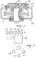
- Figure 3 is a schematic front view, shown in phantom lines, of the hydraulic circuit of the transmission unit according to the invention;
- Figure 4 is a schematic plan view, shown in phantom lines, of the hydraulic circuit of the transmission unit according to the invention;
- Figure 5 is a diagram of the automatic management logic of the transmission unit according to the invention.
- With reference to the figures, the
reference numeral 1 generally designates a transmission unit particularly for driving screw feeders and auxiliary user devices of mixing trucks. - The
unit 1 comprises: an off-center distribution device 2; areduction unit 3, which is functionally connected to the off-center distribution device 2 and can be associated with the screw feeders of a mixing truck; a mainfriction clutch device 4, which is interposed between the off-center distribution device 2 and thereduction unit 3; adevice 5 for reversing the direction of rotation of the screw feeders; and an auxiliaryfriction clutch device 6 for thereversing device 5. - The auxiliary
friction clutch device 6 is in the disengaged configuration when the mainfriction clutch device 4 is in the engaged configuration; the mainfriction clutch device 4 is in the disengaged configuration when the auxiliaryfriction clutch device 6 is in the engaged configuration, and there is a neutral configuration in which both friction clutch devices, the main one 4 and the auxiliary one 6, are disengaged. - The off-
center distribution device 2 comprises acontainment case 7, which rotatably supports aninput shaft 8, which can be connected to an external power take-off of a farming tractor and on which aninput gear 9 is keyed. - The
input gear 9 meshes with a first drivengear 10, which is keyed on a drivenshaft 11 supported rotatably by thecase 7, and with a second drivengear 12, which is supported rotatably by thecase 7 and has internal slottedprofiles 13 for connection to auxiliary user devices U, such as for example the pumps used for the hydraulic actuation of the elements of theunit 1 or of other services of the truck. - The
reduction unit 3 is constituted by a first epicyclic reduction unit with one or more stages, which is shown only partially since it is of a conventionally known type; the shaft of its input sun gear has been designated by thereference numeral 14. - The
reversing device 5 is arranged downstream of the off-center distribution device 2 and upstream of the mainfriction clutch device 4 along the direction of motion input; it is constituted by an epicyclic gear system, particularly by a second single-stage epicyclic reduction unit. - The main
friction clutch device 4 is of the multiple-disk oil-bath type, which is per se known, and comprises aclutch bell 15, which is keyed onto the shaft of theinput sun gear 14 of thereduction unit 3 and is mounted rotatably on the drivenshaft 11 of the off-center distribution device 2. - The
clutch bell 15 is provided internally with slots, recesses or the like for accommodating traction fins formed in drivendisks 16. Ahub 17 is keyed onto the drivenshaft 11, and slots, recesses or the like are formed therein for accommodating driving fins formed indriving disks 18 which are interposed between the drivendisks 16. - In order to actuate the main
friction clutch device 4, there are first fluid-operated actuation means, which are constituted by a first piston 19 (which is annular and of the single-acting type), which forms, in cooperation with acollar 20 formed on the drivenshaft 11, afirst chamber 21, which is connected to a hydraulic circuit C, and by first elastic contrast means, which are constituted byfirst springs 22, which are interposed between thefirst piston 19, on the opposite side with respect to thefirst chamber 21, and a firstcomplementary disk 23, which is keyed onto the drivenshaft 11. - The
reversing device 5 comprises: asun gear 24, which is formed on the drivenshaft 11 of the off-center distribution device 2; at least oneplanetary gear 25, which is supported rotatably by agear carrier 26, which is mounted rotatably on the drivenshaft 11; and aring gear 27 with internal teeth, which rotates rigidly with theclutch bell 15 and meshes with theplanetary gears 25. - The auxiliary
friction clutch device 6 is of the multiple-disk oil-bath type and comprisesdisks 28 provided with traction fins accommodated in grooves, recesses or the like which are formed on the outer lateral surface of thegear carrier 26 and are interposed betweenlocking disks 29, which are provided with respective traction fins accommodated in slots, recesses or the like formed on the internal surface of a containment body of the auxiliaryfriction clutch device 6, which is advantageously constituted by thecase 7. - However, alternative embodiments of the body for containing the auxiliary
friction clutch device 6 are also possible and might be constituted for example by a separate body which is coupled to thecase 7 by means of a flange. - Second fluid-operated actuation means 30 are provided for the actuation of the auxiliary
friction clutch device 6. - Moreover, the
transmission unit 1 comprises abraking device 31, (negative safety device, which locks the screw feeders if no motion is occurring), which acts on theclutch bell 15 or on the shaft of theinput sun gear 14 of thereduction unit 3 and is suitable to block the actuation of the screw feeders with both friction clutch devices, the main one 4 and the auxiliary one 6, in the disengaged configuration. - The
braking device 31 is constituted by abrake disc 32, which rotates rigidly with the outer lateral surface of theclutch bell 15, and by at least oneabutment surface 33, which is rotationally fixed and is formed within acontainment body 34, which is rigidly coupled to thecase 7 and to thecasing 35 of thereduction unit 3. - Means for the pressure clamping of the
brake disc 32 against theabutment surfaces 33 and fluid-operated means for deactivating said clamping means are further provided and are conveniently integrated with respect to the second fluid-operated actuation means 30. - The second fluid-operated actuation means 30 are constituted by a second piston 36 (which is annular and of the single-acting type), which is locked rotationally by means of a pin, not shown, and cooperates with an
auxiliary piston 37, which is interposed between it and thecontainment body 34, and second elastic contrast means, which are constituted bysecond springs 38 interposed between thesecond piston 36 and a secondcomplementary disk 39, which is rigidly coupled to thecase 7. - The
second springs 38 act as elastic pusher means, which press thesecond piston 36 against thebrake disc 32, keeping it in contact with theabutment surface 33, the face of thesecond piston 36 also constituting anadditional abutment surface 33 for thebrake disc 32. - A
second chamber 40 is formed between thesecond piston 36 and theauxiliary piston 37 and is connected to the hydraulic circuit C, while between theauxiliary piston 37 and thecontainment body 34 with which it abuts there is anauxiliary chamber 41, which is connected to the hydraulic circuit C. - The oil that enters the second chamber 40 (the
auxiliary chamber 41 being connected to the discharge) pushes thesecond piston 36 toward the auxiliaryfriction clutch device 6, closing it and simultaneously deactivating the braking device 31 (theauxiliary piston 37 remaining in abutment against the containment body 34). - The oil that enters the auxiliary chamber 41 (the
second chamber 40 being connected to the discharge) pushes theauxiliary piston 37 away from thebraking device 31, deactivating it, but without engaging the auxiliaryfriction clutch device 6; i.e., theauxiliary piston 37 advances until it abuts against a surface formed in thecase 7, thus assuming a neutral configuration, in which it acts neither on the auxiliaryfriction clutch device 6 nor on thebraking device 31. - The hydraulic circuit C comprises
connectors 42 for branching from thefirst chamber 21, which are formed in the drivenshaft 11 and are connected to anaxial duct 43, which is formed in said driven shaft and is associated with afirst channel 44 for connection to asource 45 of pressurized fluid (oil). - Further, the hydraulic circuit C comprises a
second channel 46 and athird channel 47, which is a branch of thefirst connection channel 44, for connecting respectively thesecond chamber 40 and theauxiliary chamber 41 to thesource 45. - The
source 45 comprises a hydraulic control unit, which in turn is constituted by apump 48, for example of the rotor type, which is associated with theinput shaft 8 of the off-center distribution device 2 and is provided with anintake port 49 and with adischarge port 50, which are connected to the internal volume of thecase 7, and with a slide valve 51 (with four ways and three positions), which is interposed between thedelivery port 52 and thedischarge port 50 of thepump 48 and the three connectingchannels - A
pressure limiting valve 53 is provided at the delivery duct of thepump 48. - Two
electric valves 54 drive the slide valve 51 in order to connect selectively thedelivery port 52 to the first connecting channel 44 (and therefore also to the third connecting channel 47) or to the second connectingchannel 46 and in order to connect thedischarge port 50 respectively to the second connectingchannel 46 or to the first connecting channel 44 (and therefore also to the third connecting channel 47). - By feeding oil into the first connecting
channel 44 and therefore also into thethird channel 47 and connecting to the discharge the second connectingchannel 46, thebraking device 31 is deactivated, the mainfriction clutch device 4 is closed, and the auxiliaryfriction clutch device 6 is kept open. - In this active configuration, the
clutch bell 15, and therefore the shaft of theinput sun gear 14 of thereduction unit 3, is turned by the drivenshaft 11; therefore, the screw feeders are turned for work. - The driven
shaft 11 and theclutch bell 15 turn rigidly thereversing device 5. - By feeding oil into the second connecting
channel 46 and connecting to the discharge the first connectingchannel 44, thebraking device 31 is deactivated, the auxiliaryfriction clutch device 6 is closed, and the mainfriction clutch device 4 is kept open. - In this configuration in which the rotary motion of the screw feeders is reversed, the epicyclic gear system that constitutes the reversing
device 5 behaves like an ordinary gear system: thegear carrier 26 is rigidly coupled to thecase 7 and therefore fixed, and accordingly thesun gear 24 turns about their own fixed axes theplanetary gears 25, which in turn rotate thering gear 27, and therefore theclutch bell 15 and the shaft of theinput sun gear 14 of thereduction unit 3, in the opposite direction with respect to the work direction. - Finally, the
transmission unit 1 is provided with a central control andactuation unit 55, which is associated with the source 45 (hydraulic control unit:pump 48, slide valve 51, and electric valves 54) and with a plurality of detection devices, including in particular - a
first sensor 56 for detecting the pressure at the input of the hydraulic circuit C; - a
second sensor 57 for detecting the actuation pressure of the mainfriction clutch device 4; - a third sensor 58 for detecting the actuation pressure of the auxiliary friction
clutch device 6; - a
first detector 59 for detecting the rotation rate (speed) in input to the drivenshaft 11; - a
second detector 60 for detecting the rotation rate (speed) in output on theclutch bell 15; - a
sensor 61 for detecting torque at the input on the drivenshaft 11 or on theinput shaft 8. - The central control and
actuation unit 55 allows to manage automatically the operation of theunit 1 and in particular the reversal of the motion of the screw feeders (by detecting any blockage, reversing motion only for the time needed for unblocking, and restoring normal operating conditions) and to lock automatically theunit 1 in case of abnormal operation. - In particular, the automatic management of the
unit 1 consists in: - detecting any overload affecting the screw feeders according to a first criterion and/or a second criterion;
- interrupting the active transmission of rotary motion to the screw feeders (setting to neutral; disengagement of the main friction clutch device 4);
- reversing the direction of rotation of the screw feeders (deactivation of the
braking device 31 and engagement of the auxiliary friction clutch device 6) for a time interval that can be determined according to a first principle or a second principle; - interrupting the transmission of the reversed motion to the screw feeders (disengagement of the auxiliary friction clutch device); and
- restoring the active transmission of rotary motion to the screw feeders, after excluding causes of hindrance determined according to a first rule, a second rule, a third rule and a fourth rule.
- Further, the automatic management of the
unit 1 allows to block the active transmission of rotary motion to the screw feeders if at least one of said causes of hindrance is detected during said transmission. - The first criterion consists in detecting (by means of the torque sensor 61) the torque (torsional moment) transmitted to the screw feeders and in comparing the detected value with a maximum reference value, overload being determined by the positive difference of the detected value with respect to the maximum reference value.
- The second criterion consists in detecting the difference between the rotation rate in input and in output (by means of the first and
second detectors 59 and 60) from the screw feeders, in comparing said difference with a maximum reference threshold, overload being determined by the positive difference between the detected difference and the maximum reference threshold. - The first principle for determining reversal time consists in time-controlling it (timer).
- The second principle for determining reversal time consists in detecting the torque (torsional moment) transmitted to the screw feeders and in comparing the detected value with a maximum reference value, reversal time being determined by the negative difference between the detected value and the maximum reference value.
- The first rule for determining a cause of failure to restore the working rotation conditions or their blockage consists in detecting the difference between the rotation rate in input and in output from the screw feeders (by means of the first and
second detectors 59 and 60) and in comparing this difference with a maximum reference threshold, the cause of the hindrance/blockage being determined by the positive variation between the detected difference and the maximum reference threshold. - The second rule for determining a cause of failure to restore the work rotation conditions or of their blocking consists in detecting the supply pressure of the hydraulic circuit that actuates the main and auxiliary friction
clutch devices - The third rule for determining a cause of failure to restore the work rotation conditions or of their blocking consists in detecting the closing pressure of the main and auxiliary friction
clutch devices - The fourth rule for determining a cause of failure to restore the work rotation conditions or of their blocking consists in detecting the presence/position of the protection devices, the cause being given by their absence.
- In practice it has been found that the described invention achieves the intended aim and objects.
- The transmission unit according to the invention in fact allows to reverse the motion of the screw feeders of a mixing truck simply and rapidly without requiring any human intervention and without having to disconnect the external power take-off or reverse the travel of the truck and keeping unchanged the actuation and functionality of the auxiliary user devices, particularly of the pump that feeds the hydraulic circuit and of all the detection and measurement devices.
- Further, the transmission unit according to the invention, by controlling the reversal time, allows to limit the loads that bear on the transmission elements, which move in reverse with respect to the direction in which for which they are designed.
- Finally, the transmission unit according to the invention allows to manage automatically the detection of any blockage of the screw feeders and the maneuvers for reversing their motion until normal operating conditions are restored, to the full advantage of greater safety for operators and of greater protection of the transmission elements.
- The invention thus conceived is susceptible of numerous modifications and variations, all of which are within the scope of the appended claims.
- All the details may further be replaced with other technically equivalent ones.
- In practice, the materials used, as well as the shapes and the dimensions, may be any according to requirements without thereby abandoning the scope of the protection of the appended claims.
- The disclosures in Italian Patent Application No. MO2004A000226 from which this application claims priority are incorporated herein by reference.
- Where technical features mentioned in any claim are followed by reference signs, those reference signs have been included for the sole purpose of increasing the intelligibility of the claims and accordingly, such reference signs do not have any limiting effect on the interpretation of each element identified by way of example by such reference signs.
Claims (32)
- A transmission unit particularly for driving screw feeders and auxiliary user devices of mixing trucks, comprising: an off-center distribution device, which can be associated with an external power take-off and forms couplings for the connection of auxiliary user devices; a reduction unit, which is functionally connected to said off-center distribution device and can be associated with the screw feeders of a mixing truck; and a main friction clutch device, which is interposed between said off-center distribution device and said reduction unit, characterized in that it comprises a device for reversing the direction of rotation of said screw feeders and an auxiliary friction clutch device for said reversing device.
- The unit according to claim 1, characterized in that said reversing device and said auxiliary friction clutch device are arranged upstream of said main friction clutch device and downstream of said off-center distribution device along the direction of input of the motion.
- The unit according to claim 1, characterized in that said reversing device comprises an epicyclic gear system.
- The unit according to claim 1, characterized in that said reduction unit is constituted by a first epicyclic reduction unit with at least one stage.
- The unit according to claim 3, characterized in that said epicyclic gear system is a second single-stage epicyclic reduction unit.
- The unit according to claim 4, characterized in that said main friction clutch device comprises a clutch bell, which is keyed to a shaft of an input sun gear of said first epicyclic reduction unit and with which driven disks are rigidly rotationally associated, and a hub, which is keyed on a driven shaft of said off-center distribution device and with which driving disks interposed between said driven disks are rotationally rigidly associated.
- The unit according to claim 6, characterized in that said reversing device comprises a sun gear, which is formed on said driven shaft of the off-center distribution device, at least one planetary gear supported by a gear carrier which is mounted so that it can rotate on said driven shaft, and a ring gear with internal teeth, which rotates rigidly with said clutch bell and is coupled to said planetary gears.
- The unit according to claim 7, characterized in that said auxiliary friction clutch device comprises disks which are rotationally rigidly associated with an outer lateral surface of said gear carrier and are interposed between locking disks, which are rotationally rigidly associated with a body for containing said auxiliary friction clutch device.
- The unit according to claim 6, characterized in that it comprises first fluid-operated actuation means for said main friction clutch device.
- The unit according to claim 9, characterized in that said first actuation means comprise a first piston, which forms a first chamber which is connected to a hydraulic circuit, and first elastic contrast means, which are interposed between said first piston and a first complementary disk, which is keyed to said driven shaft.
- The unit according to claim 10, characterized in that it comprises second fluid-operated actuation means for actuating said auxiliary friction clutch device.
- The unit according to claim 11, characterized in that said second actuation means comprise a second piston, which forms a second chamber which is connected to said hydraulic circuit, and second elastic contrast means, which are interposed between said second piston and a second complementary disk, which is rigidly coupled to said containment body.
- The unit according to claim 6, characterized in that it comprises a braking device, which acts on said clutch bell or on said shaft of the input sun gear of said first epicyclic reduction unit and is suitable to prevent the actuation of said screw feeders with both of said main and auxiliary friction clutch devices in the disengaged configuration.
- The unit according to claim 13, characterized in that said braking device comprises a brake disc, which is rotationally rigidly coupled to the outer lateral surface of said clutch bell, and at least one abutment surface, which is rotationally fixed and is formed on the internal surface of a containment body and/or on a face of said second piston.
- The unit according to claim 14, characterized in that it comprises means for clamping by pressure said brake disc against said abutment surfaces.
- The unit according to claim 15, characterized in that said pressure clamping means comprise elastic pusher means, which act between said brake disc and/or said abutment surfaces and an abutment element which is rigidly coupled to said containment body, fluid-operated means for deactivating said pressure clamping means being provided.
- The unit according to claim 16, characterized in that said fluid-operated deactivation means comprise a third piston, which forms a third chamber connected to said hydraulic circuit.
- The unit according to claim 17, characterized in that said second piston coincides with said third piston and said second elastic means coincide with said elastic pusher means, an auxiliary piston being provided which is interposed between said second piston and said containment body and forms, in cooperation with them and in a mutually opposite arrangement, said second chamber and an auxiliary chamber, which is connected to said hydraulic circuit, said chambers forming said third chamber for the deactivation of said pressure clamping means respectively when said auxiliary friction clutch device is in the engaged configuration and said main friction clutch device is in the engaged configuration.
- The unit according to claim 18, characterized in that said hydraulic circuit comprises branches that extend from said first chamber, are formed in said driven shaft and are connected to an actual duct, which is formed in said driven shaft and is associated with a first channel for connection to a source of pressurized fluid.
- The unit according to claim 19, characterized in that said hydraulic circuit comprises a second and/or a third channel respectively for connecting said second chamber and said auxiliary chamber to said source.
- The unit according to claim 20, characterized in that said third connecting channel is a branch of said first connecting channel.
- The unit according to claim 21, characterized in that said source comprises a pump, which is associated with an input shaft of said off-center distribution device and is provided with an intake port and a discharge port, which are connected to internal volume of a containment case of said off-center distribution device, a slide valve interposed between a delivery port and a discharge port of said pump and said connecting channels, and electric valves for driving said slide valve for the selective connection of said delivery port to said first or second connecting channel and of said discharge port respectively to said second or first connecting channel.
- A method for driving screw feeders and auxiliary user devices of mixing trucks, characterized in that it comprises the steps of:- detecting an overload of the screw feeders of a mixing truck according to a first criterion and/or a second criterion;- interrupting the active transmission of rotary motion to said screw feeders;- reversing the direction of rotation of said screw feeders for a time interval that can be determined according to a first principle or a second principle;- interrupting the transmission of the reversed motion to said screw feeders; and- restoring the active transmission of rotary motion to said screw feeders, after excluding causes of hindrance determined according to a first rule, a second rule, a third rule and a fourth rule.
- The method according to claim 23, characterized in that it comprises blocking the active rotary motion transmission to said screw feeders if at least one of said causes of hindrance is detected.
- The method according to claim 23, characterized in that said first criterion consists in detecting the torque transmitted to said screw feeders and in comparing the detected value to a maximum reference value, said overload being determined by the positive difference of the detected value with respect to the maximum reference value.
- The method according to claim 23, characterized in that said second criterion consists in detecting a difference between a rotation rate in input and in output from said screw feeders, in comparing said difference with a maximum reference threshold, said overload being determined by a positive difference between a detected difference and said maximum reference threshold.
- The method according to claim 23, characterized in that said first principle consists in timing said reversal step.
- The method according to claim 23, characterized in that said second principle consists in detecting a torque transmitted to said screw feeders and in comparing a detected value with a maximum reference value, said interval being determined by a negative difference between a detected value and said maximum reference value.
- The method according to claim 23, characterized in that said first rule consists in detecting a difference between a rotation rate in input and in output from said screw feeders, in comparing said difference with a maximum reference threshold, said cause being determined by a positive difference between a detected difference and said maximum reference threshold.
- The method according to claim 23, characterized in that said second rule consists in detecting a supply pressure of said hydraulic circuit for actuating the main and auxiliary friction clutch devices and in comparing a detected pressure with a minimum reference value, said cause being determined by a negative difference between the detected value and said minimum reference value.
- The method according to claim 23, characterized in that said third rule consists in detecting a closing pressure of said main and auxiliary friction clutch devices and comparing a detected value with a minimum reference value, said cause being determined by a negative difference between said detected value and said minimum reference value.
- The method according to claim 23, characterized in that said fourth rule consists in detecting a position of protection devices.
Priority Applications (1)
| Application Number | Priority Date | Filing Date | Title |
|---|---|---|---|
| PL05019303T PL1634758T3 (en) | 2004-09-09 | 2005-09-06 | Transmission unit particularly for driving the screw feeders and auxiliary user devices of mixing trucks |
Applications Claiming Priority (1)
| Application Number | Priority Date | Filing Date | Title |
|---|---|---|---|
| IT000226A ITMO20040226A1 (en) | 2004-09-09 | 2004-09-09 | TRANSMISSION GROUP PARTICULARLY FOR THE OPERATION OF THE AUGERS OF AUXILIARY USERS OF MIXING TRUCKS. |
Publications (3)
| Publication Number | Publication Date |
|---|---|
| EP1634758A1 true EP1634758A1 (en) | 2006-03-15 |
| EP1634758B1 EP1634758B1 (en) | 2010-06-02 |
| EP1634758B8 EP1634758B8 (en) | 2010-07-14 |
Family
ID=35448353
Family Applications (1)
| Application Number | Title | Priority Date | Filing Date |
|---|---|---|---|
| EP05019303A Expired - Lifetime EP1634758B8 (en) | 2004-09-09 | 2005-09-06 | Transmission unit particularly for driving the screw feeders and auxiliary user devices of mixing trucks |
Country Status (8)
| Country | Link |
|---|---|
| US (1) | US7484437B2 (en) |
| EP (1) | EP1634758B8 (en) |
| AT (1) | ATE469545T1 (en) |
| DE (1) | DE602005021587D1 (en) |
| DK (1) | DK1634758T3 (en) |
| ES (1) | ES2343966T3 (en) |
| IT (1) | ITMO20040226A1 (en) |
| PL (1) | PL1634758T3 (en) |
Cited By (1)
| Publication number | Priority date | Publication date | Assignee | Title |
|---|---|---|---|---|
| WO2018117944A1 (en) * | 2016-12-22 | 2018-06-28 | Scania Cv Ab | Power take-off and parts thereof |
Families Citing this family (9)
| Publication number | Priority date | Publication date | Assignee | Title |
|---|---|---|---|---|
| MX2011012456A (en) | 2009-05-20 | 2012-01-12 | Xyleco Inc | Processing hydrocarbon-containing materials. |
| US8657485B2 (en) * | 2010-07-12 | 2014-02-25 | Roto-Mix, Llc | Agricultural mixer with hydraulic drive system including jam detection and resolution features and method of using same |
| US8770826B2 (en) * | 2010-09-16 | 2014-07-08 | Jay-Lor International Inc. | Gearbox with breather system |
| DE202013004051U1 (en) * | 2013-04-29 | 2014-07-30 | Gkn Walterscheid Gmbh | Transmission for crusher |
| US9751058B2 (en) * | 2015-09-04 | 2017-09-05 | Patz Corporation | Agricultural feed mixer transmission torque sensor assembly |
| DE202015104960U1 (en) * | 2015-09-18 | 2016-12-21 | Trioliet B. V. | feed mixer |
| US10174830B2 (en) * | 2015-11-30 | 2019-01-08 | Borgwarner Inc. | Active transfer case with lube management valve |
| CN112203770B (en) | 2018-05-23 | 2023-01-03 | 维米尔制造公司 | Chopping machine for crushing bulk material |
| US11185833B2 (en) * | 2018-05-31 | 2021-11-30 | Kuhn North America, Inc. | Control system for a livestock feed mixer |
Citations (11)
| Publication number | Priority date | Publication date | Assignee | Title |
|---|---|---|---|---|
| GB676055A (en) * | 1949-07-22 | 1952-07-23 | Daimler Benz Ag | Improvements relating to change-speed gearing |
| US2912885A (en) * | 1956-03-05 | 1959-11-17 | Continental Motors Corp | Planetary bevel gear reversing transmission |
| US3523411A (en) * | 1968-03-04 | 1970-08-11 | Sperry Rand Corp | Forage harvester drive |
| US3924491A (en) * | 1973-05-30 | 1975-12-09 | Volkswagenwerk Ag | Hydrodynamic-mechanical transmission for automobiles |
| EP0001348A1 (en) * | 1977-09-22 | 1979-04-04 | Vickers Shipbuilding Group Limited | Gear transmissions |
| EP0054253A1 (en) * | 1980-12-15 | 1982-06-23 | Deere & Company | Reversing gear |
| GB2169366A (en) * | 1985-01-04 | 1986-07-09 | Kidd Farm Machinery | Drive reversal mechanism |
| DE19918552A1 (en) * | 1999-04-23 | 2000-10-26 | Deere & Co | Harvester |
| EP1064840A1 (en) * | 1999-07-02 | 2001-01-03 | Gyrax | Driving system for a forage distributing machine or another in order to get a selective driving for its cutting roller, and distributing machine with such a device |
| US6318056B1 (en) * | 1998-11-11 | 2001-11-20 | Claas Saulgau Gmbh | Device for monitoring the intake subassembly of an agricultural harvesting machine |
| US20040093841A1 (en) * | 2002-09-06 | 2004-05-20 | Steffen Clauss | Detection arrangement for the detection of a crop jam in a harvesting machine |
-
2004
- 2004-09-09 IT IT000226A patent/ITMO20040226A1/en unknown
-
2005
- 2005-09-02 US US11/217,610 patent/US7484437B2/en not_active Expired - Lifetime
- 2005-09-06 ES ES05019303T patent/ES2343966T3/en not_active Expired - Lifetime
- 2005-09-06 DK DK05019303.6T patent/DK1634758T3/en active
- 2005-09-06 AT AT05019303T patent/ATE469545T1/en not_active IP Right Cessation
- 2005-09-06 PL PL05019303T patent/PL1634758T3/en unknown
- 2005-09-06 EP EP05019303A patent/EP1634758B8/en not_active Expired - Lifetime
- 2005-09-06 DE DE602005021587T patent/DE602005021587D1/en not_active Expired - Lifetime
Patent Citations (11)
| Publication number | Priority date | Publication date | Assignee | Title |
|---|---|---|---|---|
| GB676055A (en) * | 1949-07-22 | 1952-07-23 | Daimler Benz Ag | Improvements relating to change-speed gearing |
| US2912885A (en) * | 1956-03-05 | 1959-11-17 | Continental Motors Corp | Planetary bevel gear reversing transmission |
| US3523411A (en) * | 1968-03-04 | 1970-08-11 | Sperry Rand Corp | Forage harvester drive |
| US3924491A (en) * | 1973-05-30 | 1975-12-09 | Volkswagenwerk Ag | Hydrodynamic-mechanical transmission for automobiles |
| EP0001348A1 (en) * | 1977-09-22 | 1979-04-04 | Vickers Shipbuilding Group Limited | Gear transmissions |
| EP0054253A1 (en) * | 1980-12-15 | 1982-06-23 | Deere & Company | Reversing gear |
| GB2169366A (en) * | 1985-01-04 | 1986-07-09 | Kidd Farm Machinery | Drive reversal mechanism |
| US6318056B1 (en) * | 1998-11-11 | 2001-11-20 | Claas Saulgau Gmbh | Device for monitoring the intake subassembly of an agricultural harvesting machine |
| DE19918552A1 (en) * | 1999-04-23 | 2000-10-26 | Deere & Co | Harvester |
| EP1064840A1 (en) * | 1999-07-02 | 2001-01-03 | Gyrax | Driving system for a forage distributing machine or another in order to get a selective driving for its cutting roller, and distributing machine with such a device |
| US20040093841A1 (en) * | 2002-09-06 | 2004-05-20 | Steffen Clauss | Detection arrangement for the detection of a crop jam in a harvesting machine |
Cited By (1)
| Publication number | Priority date | Publication date | Assignee | Title |
|---|---|---|---|---|
| WO2018117944A1 (en) * | 2016-12-22 | 2018-06-28 | Scania Cv Ab | Power take-off and parts thereof |
Also Published As
| Publication number | Publication date |
|---|---|
| US20060050604A1 (en) | 2006-03-09 |
| EP1634758B1 (en) | 2010-06-02 |
| DE602005021587D1 (en) | 2010-07-15 |
| ITMO20040226A1 (en) | 2004-12-09 |
| ES2343966T3 (en) | 2010-08-13 |
| ATE469545T1 (en) | 2010-06-15 |
| EP1634758B8 (en) | 2010-07-14 |
| PL1634758T3 (en) | 2010-10-29 |
| US7484437B2 (en) | 2009-02-03 |
| DK1634758T3 (en) | 2010-10-04 |
Similar Documents
| Publication | Publication Date | Title |
|---|---|---|
| US7484437B2 (en) | Transmission unit particularly for driving the screw feeders and auxiliary user devices of mixing trucks | |
| EP3768066B1 (en) | Agricultural baler and method of protecting such baler from overload damage | |
| EP2557911B1 (en) | Forage harvesters | |
| EP0226426B1 (en) | Two speed gearbox | |
| US6718746B2 (en) | Drive arrangement for ensilage harvester discharge spout | |
| US7736270B2 (en) | Control valve arrangement for controlling a start clutch of an automatic gearbox | |
| EP3032124B1 (en) | System and method for preventing centrifugal clutch lock-ups within a transmission of a work vehicle | |
| WO2015023301A1 (en) | Pto driven chipper system | |
| US6131714A (en) | Auxiliary drive for utility vehicle and method of operation thereof | |
| US4245526A (en) | Mining machine haulage transmission | |
| CN106030158B (en) | Vehicle drive train with torque transmitting device operating under fluid pressure | |
| US4456109A (en) | Transmission coupling including a clutch-brake combination | |
| US7186201B2 (en) | Active combine rotor deceleration | |
| US9222561B2 (en) | Transmission for use in shredding machines | |
| JPS608194B2 (en) | power spanner | |
| RU2343671C1 (en) | Strip sowing machine | |
| JP2843787B2 (en) | Auger drive mechanism | |
| EP1236606B1 (en) | Reduction unit particularly for actuating the screw feeders of mixing trucks and auxiliary elements | |
| JPS6015706Y2 (en) | Work machine power take-off device for agricultural tractors | |
| JP3666049B2 (en) | Control method of reverse clutch in transmission | |
| CS232295B1 (en) | Safety clutch mechanism | |
| JPH0560155A (en) | Braking device for rotary mechanism | |
| JPS5930364B2 (en) | Work machine power take-off device for agricultural tractors |
Legal Events
| Date | Code | Title | Description |
|---|---|---|---|
| PUAI | Public reference made under article 153(3) epc to a published international application that has entered the european phase |
Free format text: ORIGINAL CODE: 0009012 |
|
| AK | Designated contracting states |
Kind code of ref document: A1 Designated state(s): AT BE BG CH CY CZ DE DK EE ES FI FR GB GR HU IE IS IT LI LT LU LV MC NL PL PT RO SE SI SK TR |
|
| AX | Request for extension of the european patent |
Extension state: AL BA HR MK YU |
|
| RIN1 | Information on inventor provided before grant (corrected) |
Inventor name: MORA, FAUSTO Inventor name: BRUNAZZI, ACHILLE Inventor name: GALLO, ANDREA |
|
| 17P | Request for examination filed |
Effective date: 20060915 |
|
| 17Q | First examination report despatched |
Effective date: 20061012 |
|
| AKX | Designation fees paid |
Designated state(s): AT BE BG CH CY CZ DE DK EE ES FI FR GB GR HU IE IS IT LI LT LU LV MC NL PL PT RO SE SI SK TR |
|
| GRAP | Despatch of communication of intention to grant a patent |
Free format text: ORIGINAL CODE: EPIDOSNIGR1 |
|
| RIC1 | Information provided on ipc code assigned before grant |
Ipc: A01K 5/00 20060101AFI20091117BHEP |
|
| GRAS | Grant fee paid |
Free format text: ORIGINAL CODE: EPIDOSNIGR3 |
|
| GRAA | (expected) grant |
Free format text: ORIGINAL CODE: 0009210 |
|
| AK | Designated contracting states |
Kind code of ref document: B1 Designated state(s): AT BE BG CH CY CZ DE DK EE ES FI FR GB GR HU IE IS IT LI LT LU LV MC NL PL PT RO SE SI SK TR |
|
| REG | Reference to a national code |
Ref country code: GB Ref legal event code: FG4D |
|
| REG | Reference to a national code |
Ref country code: CH Ref legal event code: EP |
|
| RAP2 | Party data changed (patent owner data changed or rights of a patent transferred) |
Owner name: COMER INDUSTRIES S.P.A. |
|
| REG | Reference to a national code |
Ref country code: IE Ref legal event code: FG4D Ref country code: NL Ref legal event code: T3 |
|
| REF | Corresponds to: |
Ref document number: 602005021587 Country of ref document: DE Date of ref document: 20100715 Kind code of ref document: P |
|
| REG | Reference to a national code |
Ref country code: ES Ref legal event code: FG2A Ref document number: 2343966 Country of ref document: ES Kind code of ref document: T3 |
|
| REG | Reference to a national code |
Ref country code: DK Ref legal event code: T3 |
|
| PG25 | Lapsed in a contracting state [announced via postgrant information from national office to epo] |
Ref country code: SE Free format text: LAPSE BECAUSE OF FAILURE TO SUBMIT A TRANSLATION OF THE DESCRIPTION OR TO PAY THE FEE WITHIN THE PRESCRIBED TIME-LIMIT Effective date: 20100602 Ref country code: LT Free format text: LAPSE BECAUSE OF FAILURE TO SUBMIT A TRANSLATION OF THE DESCRIPTION OR TO PAY THE FEE WITHIN THE PRESCRIBED TIME-LIMIT Effective date: 20100602 |
|
| REG | Reference to a national code |
Ref country code: PL Ref legal event code: T3 |
|
| LTIE | Lt: invalidation of european patent or patent extension |
Effective date: 20100602 |
|
| PG25 | Lapsed in a contracting state [announced via postgrant information from national office to epo] |
Ref country code: SI Free format text: LAPSE BECAUSE OF FAILURE TO SUBMIT A TRANSLATION OF THE DESCRIPTION OR TO PAY THE FEE WITHIN THE PRESCRIBED TIME-LIMIT Effective date: 20100602 Ref country code: FI Free format text: LAPSE BECAUSE OF FAILURE TO SUBMIT A TRANSLATION OF THE DESCRIPTION OR TO PAY THE FEE WITHIN THE PRESCRIBED TIME-LIMIT Effective date: 20100602 Ref country code: AT Free format text: LAPSE BECAUSE OF FAILURE TO SUBMIT A TRANSLATION OF THE DESCRIPTION OR TO PAY THE FEE WITHIN THE PRESCRIBED TIME-LIMIT Effective date: 20100602 Ref country code: LV Free format text: LAPSE BECAUSE OF FAILURE TO SUBMIT A TRANSLATION OF THE DESCRIPTION OR TO PAY THE FEE WITHIN THE PRESCRIBED TIME-LIMIT Effective date: 20100602 |
|
| PG25 | Lapsed in a contracting state [announced via postgrant information from national office to epo] |
Ref country code: GR Free format text: LAPSE BECAUSE OF FAILURE TO SUBMIT A TRANSLATION OF THE DESCRIPTION OR TO PAY THE FEE WITHIN THE PRESCRIBED TIME-LIMIT Effective date: 20100903 Ref country code: CY Free format text: LAPSE BECAUSE OF FAILURE TO SUBMIT A TRANSLATION OF THE DESCRIPTION OR TO PAY THE FEE WITHIN THE PRESCRIBED TIME-LIMIT Effective date: 20100602 |
|
| PG25 | Lapsed in a contracting state [announced via postgrant information from national office to epo] |
Ref country code: EE Free format text: LAPSE BECAUSE OF FAILURE TO SUBMIT A TRANSLATION OF THE DESCRIPTION OR TO PAY THE FEE WITHIN THE PRESCRIBED TIME-LIMIT Effective date: 20100602 |
|
| PG25 | Lapsed in a contracting state [announced via postgrant information from national office to epo] |
Ref country code: BE Free format text: LAPSE BECAUSE OF FAILURE TO SUBMIT A TRANSLATION OF THE DESCRIPTION OR TO PAY THE FEE WITHIN THE PRESCRIBED TIME-LIMIT Effective date: 20100602 Ref country code: CZ Free format text: LAPSE BECAUSE OF FAILURE TO SUBMIT A TRANSLATION OF THE DESCRIPTION OR TO PAY THE FEE WITHIN THE PRESCRIBED TIME-LIMIT Effective date: 20100602 Ref country code: IS Free format text: LAPSE BECAUSE OF FAILURE TO SUBMIT A TRANSLATION OF THE DESCRIPTION OR TO PAY THE FEE WITHIN THE PRESCRIBED TIME-LIMIT Effective date: 20101002 Ref country code: PT Free format text: LAPSE BECAUSE OF FAILURE TO SUBMIT A TRANSLATION OF THE DESCRIPTION OR TO PAY THE FEE WITHIN THE PRESCRIBED TIME-LIMIT Effective date: 20101004 Ref country code: RO Free format text: LAPSE BECAUSE OF FAILURE TO SUBMIT A TRANSLATION OF THE DESCRIPTION OR TO PAY THE FEE WITHIN THE PRESCRIBED TIME-LIMIT Effective date: 20100602 Ref country code: SK Free format text: LAPSE BECAUSE OF FAILURE TO SUBMIT A TRANSLATION OF THE DESCRIPTION OR TO PAY THE FEE WITHIN THE PRESCRIBED TIME-LIMIT Effective date: 20100602 |
|
| PLBE | No opposition filed within time limit |
Free format text: ORIGINAL CODE: 0009261 |
|
| STAA | Information on the status of an ep patent application or granted ep patent |
Free format text: STATUS: NO OPPOSITION FILED WITHIN TIME LIMIT |
|
| PG25 | Lapsed in a contracting state [announced via postgrant information from national office to epo] |
Ref country code: MC Free format text: LAPSE BECAUSE OF NON-PAYMENT OF DUE FEES Effective date: 20100930 |
|
| REG | Reference to a national code |
Ref country code: CH Ref legal event code: PL |
|
| 26N | No opposition filed |
Effective date: 20110303 |
|
| REG | Reference to a national code |
Ref country code: DE Ref legal event code: R097 Ref document number: 602005021587 Country of ref document: DE Effective date: 20110302 |
|
| PG25 | Lapsed in a contracting state [announced via postgrant information from national office to epo] |
Ref country code: LI Free format text: LAPSE BECAUSE OF NON-PAYMENT OF DUE FEES Effective date: 20100930 Ref country code: CH Free format text: LAPSE BECAUSE OF NON-PAYMENT OF DUE FEES Effective date: 20100930 |
|
| PG25 | Lapsed in a contracting state [announced via postgrant information from national office to epo] |
Ref country code: BG Free format text: LAPSE BECAUSE OF FAILURE TO SUBMIT A TRANSLATION OF THE DESCRIPTION OR TO PAY THE FEE WITHIN THE PRESCRIBED TIME-LIMIT Effective date: 20100602 Ref country code: LU Free format text: LAPSE BECAUSE OF NON-PAYMENT OF DUE FEES Effective date: 20100906 Ref country code: HU Free format text: LAPSE BECAUSE OF FAILURE TO SUBMIT A TRANSLATION OF THE DESCRIPTION OR TO PAY THE FEE WITHIN THE PRESCRIBED TIME-LIMIT Effective date: 20101203 |
|
| PG25 | Lapsed in a contracting state [announced via postgrant information from national office to epo] |
Ref country code: TR Free format text: LAPSE BECAUSE OF FAILURE TO SUBMIT A TRANSLATION OF THE DESCRIPTION OR TO PAY THE FEE WITHIN THE PRESCRIBED TIME-LIMIT Effective date: 20100602 |
|
| PG25 | Lapsed in a contracting state [announced via postgrant information from national office to epo] |
Ref country code: BG Free format text: LAPSE BECAUSE OF FAILURE TO SUBMIT A TRANSLATION OF THE DESCRIPTION OR TO PAY THE FEE WITHIN THE PRESCRIBED TIME-LIMIT Effective date: 20100902 |
|
| REG | Reference to a national code |
Ref country code: FR Ref legal event code: PLFP Year of fee payment: 11 |
|
| REG | Reference to a national code |
Ref country code: FR Ref legal event code: PLFP Year of fee payment: 12 |
|
| REG | Reference to a national code |
Ref country code: FR Ref legal event code: PLFP Year of fee payment: 13 |
|
| REG | Reference to a national code |
Ref country code: FR Ref legal event code: PLFP Year of fee payment: 14 |
|
| PGFP | Annual fee paid to national office [announced via postgrant information from national office to epo] |
Ref country code: NL Payment date: 20220926 Year of fee payment: 18 Ref country code: IE Payment date: 20220902 Year of fee payment: 18 Ref country code: GB Payment date: 20220902 Year of fee payment: 18 Ref country code: DK Payment date: 20220906 Year of fee payment: 18 Ref country code: DE Payment date: 20220902 Year of fee payment: 18 |
|
| PGFP | Annual fee paid to national office [announced via postgrant information from national office to epo] |
Ref country code: PL Payment date: 20220902 Year of fee payment: 18 Ref country code: FR Payment date: 20220902 Year of fee payment: 18 |
|
| PGFP | Annual fee paid to national office [announced via postgrant information from national office to epo] |
Ref country code: IT Payment date: 20220914 Year of fee payment: 18 Ref country code: ES Payment date: 20221003 Year of fee payment: 18 |
|
| REG | Reference to a national code |
Ref country code: DE Ref legal event code: R119 Ref document number: 602005021587 Country of ref document: DE |
|
| REG | Reference to a national code |
Ref country code: DK Ref legal event code: EBP Effective date: 20230930 |
|
| REG | Reference to a national code |
Ref country code: NL Ref legal event code: MM Effective date: 20231001 |
|
| GBPC | Gb: european patent ceased through non-payment of renewal fee |
Effective date: 20230906 |
|
| PG25 | Lapsed in a contracting state [announced via postgrant information from national office to epo] |
Ref country code: NL Free format text: LAPSE BECAUSE OF NON-PAYMENT OF DUE FEES Effective date: 20231001 |
|
| PG25 | Lapsed in a contracting state [announced via postgrant information from national office to epo] |
Ref country code: NL Free format text: LAPSE BECAUSE OF NON-PAYMENT OF DUE FEES Effective date: 20231001 |
|
| REG | Reference to a national code |
Ref country code: IE Ref legal event code: MM4A |
|
| PG25 | Lapsed in a contracting state [announced via postgrant information from national office to epo] |
Ref country code: IE Free format text: LAPSE BECAUSE OF NON-PAYMENT OF DUE FEES Effective date: 20230906 |
|
| PG25 | Lapsed in a contracting state [announced via postgrant information from national office to epo] |
Ref country code: GB Free format text: LAPSE BECAUSE OF NON-PAYMENT OF DUE FEES Effective date: 20230906 |
|
| PG25 | Lapsed in a contracting state [announced via postgrant information from national office to epo] |
Ref country code: IE Free format text: LAPSE BECAUSE OF NON-PAYMENT OF DUE FEES Effective date: 20230906 Ref country code: GB Free format text: LAPSE BECAUSE OF NON-PAYMENT OF DUE FEES Effective date: 20230906 Ref country code: FR Free format text: LAPSE BECAUSE OF NON-PAYMENT OF DUE FEES Effective date: 20230930 Ref country code: DE Free format text: LAPSE BECAUSE OF NON-PAYMENT OF DUE FEES Effective date: 20240403 |
|
| PG25 | Lapsed in a contracting state [announced via postgrant information from national office to epo] |
Ref country code: DK Free format text: LAPSE BECAUSE OF NON-PAYMENT OF DUE FEES Effective date: 20230930 |
|
| REG | Reference to a national code |
Ref country code: ES Ref legal event code: FD2A Effective date: 20241025 |
|
| PG25 | Lapsed in a contracting state [announced via postgrant information from national office to epo] |
Ref country code: PL Free format text: LAPSE BECAUSE OF NON-PAYMENT OF DUE FEES Effective date: 20230906 |
|
| PG25 | Lapsed in a contracting state [announced via postgrant information from national office to epo] |
Ref country code: PL Free format text: LAPSE BECAUSE OF NON-PAYMENT OF DUE FEES Effective date: 20230906 Ref country code: DK Free format text: LAPSE BECAUSE OF NON-PAYMENT OF DUE FEES Effective date: 20230930 |
|
| PG25 | Lapsed in a contracting state [announced via postgrant information from national office to epo] |
Ref country code: IT Free format text: LAPSE BECAUSE OF NON-PAYMENT OF DUE FEES Effective date: 20230906 |
|
| PG25 | Lapsed in a contracting state [announced via postgrant information from national office to epo] |
Ref country code: IT Free format text: LAPSE BECAUSE OF NON-PAYMENT OF DUE FEES Effective date: 20230906 |
|
| PG25 | Lapsed in a contracting state [announced via postgrant information from national office to epo] |
Ref country code: ES Free format text: LAPSE BECAUSE OF NON-PAYMENT OF DUE FEES Effective date: 20230907 |
|
| PG25 | Lapsed in a contracting state [announced via postgrant information from national office to epo] |
Ref country code: ES Free format text: LAPSE BECAUSE OF NON-PAYMENT OF DUE FEES Effective date: 20230907 |