EP1634679A2 - Extensible pole saw having separable sections - Google Patents
Extensible pole saw having separable sections Download PDFInfo
- Publication number
- EP1634679A2 EP1634679A2 EP05018027A EP05018027A EP1634679A2 EP 1634679 A2 EP1634679 A2 EP 1634679A2 EP 05018027 A EP05018027 A EP 05018027A EP 05018027 A EP05018027 A EP 05018027A EP 1634679 A2 EP1634679 A2 EP 1634679A2
- Authority
- EP
- European Patent Office
- Prior art keywords
- pole
- male plug
- sections
- female receptacle
- section
- Prior art date
- Legal status (The legal status is an assumption and is not a legal conclusion. Google has not performed a legal analysis and makes no representation as to the accuracy of the status listed.)
- Granted
Links
- 239000004020 conductor Substances 0.000 claims abstract description 5
- 230000037431 insertion Effects 0.000 claims description 2
- 238000003780 insertion Methods 0.000 claims description 2
- 238000009966 trimming Methods 0.000 abstract description 2
- 230000003247 decreasing effect Effects 0.000 description 1
- 239000000463 material Substances 0.000 description 1
Images






Classifications
-
- B—PERFORMING OPERATIONS; TRANSPORTING
- B27—WORKING OR PRESERVING WOOD OR SIMILAR MATERIAL; NAILING OR STAPLING MACHINES IN GENERAL
- B27B—SAWS FOR WOOD OR SIMILAR MATERIAL; COMPONENTS OR ACCESSORIES THEREFOR
- B27B17/00—Chain saws; Equipment therefor
- B27B17/0008—Means for carrying the chain saw, e.g. handles
-
- A—HUMAN NECESSITIES
- A01—AGRICULTURE; FORESTRY; ANIMAL HUSBANDRY; HUNTING; TRAPPING; FISHING
- A01G—HORTICULTURE; CULTIVATION OF VEGETABLES, FLOWERS, RICE, FRUIT, VINES, HOPS OR SEAWEED; FORESTRY; WATERING
- A01G3/00—Cutting implements specially adapted for horticultural purposes; Delimbing standing trees
- A01G3/08—Other tools for pruning, branching or delimbing standing trees
-
- B—PERFORMING OPERATIONS; TRANSPORTING
- B25—HAND TOOLS; PORTABLE POWER-DRIVEN TOOLS; MANIPULATORS
- B25F—COMBINATION OR MULTI-PURPOSE TOOLS NOT OTHERWISE PROVIDED FOR; DETAILS OR COMPONENTS OF PORTABLE POWER-DRIVEN TOOLS NOT PARTICULARLY RELATED TO THE OPERATIONS PERFORMED AND NOT OTHERWISE PROVIDED FOR
- B25F5/00—Details or components of portable power-driven tools not particularly related to the operations performed and not otherwise provided for
- B25F5/02—Construction of casings, bodies or handles
Definitions
- Power tools such as saws, trimmers and pruners have been used for some time to cut and shape trees and bushes. To increase their versatility, these tools have been placed on the end of poles so that elevated sections of trees or bushes can be reached for cutting without having to use a ladder or other similar device.
- the power tool is simply placed on the end of a long single pole to provide the necessary extension.
- the typical length of an extension pole makes it is difficult to transport and store.
- placing the entire power tool at the end of an extension pole makes it difficult to balance, and extremely unwieldy because all of the weight is at the end of the pole.
- the present invention is directed to an elongated pole saw for cutting and trimming trees, bushes and the like.
- the saw comprises three detachable sections, that when assembled, form an extended length saw having a battery pack on one end, and a saw or other power tool at the other end.
- the pole saw includes a first section containing a handle and battery pack, a second extension section, and a third section that contains the saw itself.
- Each of the sections contains an electrical wire that is terminated at the ends of the pole sections and are attached to adjacent pole sections via a male plug and female receptacle. In this way, the battery pack in the first section of the pole is able to deliver power through the second section to the saw in the third section.
- FIGS. 1 and 2 A pole saw 10 of the present invention is shown in FIGS. 1 and 2 in an assembled and disassembled state, respectively.
- the pole pruner 10 includes a first pole section 12, and second intermediate pole section 14, and a third pole section 16.
- the first pole section 12 includes a soft cushioning material 13 for comfortable gripping of the pole section 12, a handle 18, and a battery pack 20 for supplying power to a tool 22 at an end of the third pole section 16.
- the tool 22 is shown in the figures as a saw, but it is contemplated that any tool may be placed at the end of the third pole section 16, and the invention is not limited to a saw.
- Each of the pole sections are detachably connected to one another to form a single elongated pole for reaching elevated branches and the like without the need of a ladder. This greatly increases the safety of using such a device because a user does not have to balance himself on a ladder while using the tool.
- pole sections are connected at connecting sections 24A and 24B, which comprise female receptacles 26A and 26B and male plugs 28A and 28B on adjacent ends of each pole section, as best shown in FIG. 2.
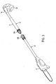
- the arrangement shown in FIG. 2 allows the second pole section 14 to be removed so that the first pole section 12 can be directly connected to the third pole section 16, as shown in
- the shortened pole arrangement may be useful when only a short reach is needed, and has the advantage of providing greater control over the pole saw 10.
- the preferred embodiment limits the number of pole sections to three, by using keying features on the male plugs 28A and 28B and female receptacles 26A and 26B, as described in greater detail below.
- the number of pole section is limited to prevent the pole length from becoming dangerously long.
- any number of pole sections may be used and still fall within the scope of the invention.
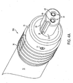
- FIGS. 4A and 4B show detailed views of the male plug 28A and female receptacle 26A connecting the first pole section 12 and the second pole section 14, and FIGS. 5A and 5B show the male plug 28B and female receptacle 26B for connecting second pole section 14 with the third pole section 16.
- the male plug 28A comprises a hollow male housing 29 that is fitted over an end of the pole section 12 and fixedly secured thereto by rivets 31 (see also FIG. 6A).
- the male housing 29 is separate from the pole section 12 in the preferred embodiment, it is contemplated that the male housing 29 be made integral with the pole section 12.
- the male housing 29 shown in FIG. 4A includes threads 30 on its outside diameter and a front stem 32 extending therefrom.
- the stem 32 includes two openings 34, two flat surfaces 36 on opposite sides, and a slot 38 along its length.
- the openings 34 hold two electrical contacts 40 that extend back through the stem 32 and connect to electrical wires 42 that run the length of the pole section (see FIG. 6A).
- the female receptacle 26A includes a housing 50 and a threaded sleeve 52.
- FIG. 4C show ⁇ the female receptacle 26A of FIG. 4B with the threaded sleeve 52 pulled slightly rearwardly to better reveal the housing 50.
- the housing 50 is folded over an end of the pole section 14 and secured on opposite sides by rivets 54 (see also FIG. 6B).
- the housing 50 defines an opening 56 for receiving the stem 32 of the male plug 28A.
- a rear portion of the opening 56 includes two apertures through which contacts 57 protrude.
- the opening 56 is generally cylindrical-shaped having flattened portions 58 on opposite sides thereof to correspond to the shape of the stem 32.
- the opening 56 further includes cavities 60 for holding the rivets 54 (only one seen in figure) so that they do not interfere with the insertion of the stem 32 into the opening 56, and a protrusion 62 corresponding to the slot 38 on the stem 32.
- the protrusion 62 slides into slot 38, and the contacts 40 engage corresponding contacts 57.
- the matching flat portions 36 and 58 on the stem 32 and in the opening 56 respectively, align the male plug 28A and female receptacle 26A and prevent their rotation relative to one another.
- the slot 38 and protrusion 62 further orients the relationship of the male plug and female receptacle for proper electrical connection.
- the threaded sleeve 52 is slidably and rotatably attached to the pole 14 and is prevented from sliding forwardly off of the pole by the housing 50.
- the sleeve 52 is threaded on its interior so that when the male plug 28A is attached to the female receptacle 26A, the sleeve 52 is slid forwardly so that it overlies and engages the threads 30 of the male plug 28A.
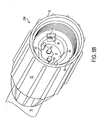
- FIGS. 5A and 5B show the male plug 28B and the female receptacle 26B for the second connecting section 24B, connecting the second pole section 14 to the third pole section 16. Similar elements in the male plug 28B and female receptacle 26B of the second connection section 24B to the first connecting section 24A are labeled with identical reference numbers. The difference in the second connection section 24B is that the stem 32 of the male plug has only a single flat surface 36, and similarly, the opening 56 in the female receptacle has only a single flat portion 58. The reason for this is explained below.
- the single and double "flat portion" keying feature in the connecting sections 24A and 24B allows the pole saw 10 to use three pole sections, as shown in FIGS. 1 and 2, or two pole sections as shown in FIG. 3, but prevents the addition of a fourth pole section, ie. another intermediate pole section 14.
- the keying feature allows the male plug 28A (having two flat portions) of the first pole section 12 to be inserted into either the female receptacle 26A (having a two flat portion) or 26B (having a single flat portion) of the second or third pole sections 14 and 16.
- the keying feature prevents a user from adding an additional fourth intermediate pole section, like pole section 14, because the male plug 28B of the pole section 14 (which has a single flat portion) does not fit into the female receptacle 26A (which as two flat portions) of the similarly made pole section 14. Therefore, a user is prevented from using more than three pole sections and thereby increasing the length of the pole saw.
- FIGS. 7 A and 7B show an alternative embodiment of the present invention.
- the male housing 28 includes a serrated front face 70 that engages a corresponding serrated face 72 on the female plug 26. Additionally, this embodiment of the invention uses a single contact 74 on the male plug and a single contact 76 on the female plug.
- the alternative embodiment is identical to the preferred embodiment previously described.
- the present invention provides the advantage of having detachable pole sections that can be separated into three shortened smaller sections, making it easier to package and transport. Also, unlike previous telescopic-type devices whose pole section diameters decrease along their length, the pole sections 12, 14 and 16 of the present invention have the same diameter and consequently, their rigidity and strength are consistent throughout its length. Furthermore, because the power source is at one end and the tool is at another, the weight of the device is divided making the product easier to handle.
Landscapes
- Life Sciences & Earth Sciences (AREA)
- Forests & Forestry (AREA)
- Mechanical Engineering (AREA)
- Engineering & Computer Science (AREA)
- Ecology (AREA)
- Biodiversity & Conservation Biology (AREA)
- Wood Science & Technology (AREA)
- Environmental Sciences (AREA)
- Details Of Connecting Devices For Male And Female Coupling (AREA)
- Cultivation Of Plants (AREA)
- Harvester Elements (AREA)
- Knives (AREA)
- Portable Power Tools In General (AREA)
- Battery Mounting, Suspending (AREA)
Abstract
Description
- Power tools, such as saws, trimmers and pruners have been used for some time to cut and shape trees and bushes. To increase their versatility, these tools have been placed on the end of poles so that elevated sections of trees or bushes can be reached for cutting without having to use a ladder or other similar device.
- In many cases, the power tool is simply placed on the end of a long single pole to provide the necessary extension. However, the typical length of an extension pole makes it is difficult to transport and store. Furthermore, placing the entire power tool at the end of an extension pole makes it difficult to balance, and extremely unwieldy because all of the weight is at the end of the pole.
- Manufacturers have attempted to overcome the burdensome pole length by using a telescopic pole that can be compressed into a smaller space. However, telescoping poles have a decreasing diameter along their length, thus providing a structurally weaker pole at the narrower sections. This increases the likelihood that the pole will break and creates a safety hazard for the user.
- Furthermore, manufacturers have attempted to solve the uneven weight distribution of the power tool by distributing weight at both ends of the pole. This has been done by placing the power tool portion at one end, and the power source portion (i.e. gas tank, battery, etc.) at the other. However, this solution typically entails having a continuous mechanical drive train or an electrical conductor (i.e. wire) connecting the tool end and the power supply end. This continuous connection often cannot be separated or shortened in conjunction with a telescopic or separable pole.
- Therefore, it would be advantageous to provide an extensible pole that can be separated into smaller components for easier transport and storage. It would be further advantageous to provide an extensible pole having uniform diameter and strength.
- The present invention is directed to an elongated pole saw for cutting and trimming trees, bushes and the like. The saw comprises three detachable sections, that when assembled, form an extended length saw having a battery pack on one end, and a saw or other power tool at the other end. The pole saw includes a first section containing a handle and battery pack, a second extension section, and a third section that contains the saw itself. Each of the sections contains an electrical wire that is terminated at the ends of the pole sections and are attached to adjacent pole sections via a male plug and female receptacle. In this way, the battery pack in the first section of the pole is able to deliver power through the second section to the saw in the third section.
- FIG. 1 shows an assembled pole pruner of the present invention;
- FIG. 2 shows a disassembled pole pruner of the present invention;
- FIG. 3 shows a pole pruner of the present invention with an intermediate pole section removed;
- FIG. 4A shows a male plug of a pole section;
- FIG. 4B shows a female receptacle of a pole section;
- FIG. 4C shows the female receptacle of FIG. 4B with a sleeve pulled rearwardly;
- FIG. 5A shows a male plug of a second pole section;
- FIG. 5B shows a female receptacle of second pole section;
- FIG. 6A shows a cut-away view of the male plug of FIG. 4A;
- FIG. 6B shows a cut-away view of the female receptacle of FIG. 4B;
- FIG. 7 A shows the male plug of an alternative embodiment of the invention; and
- FIG. 7B shows a female receptacle of an alternative embodiment of the invention.
- A
pole saw 10 of the present invention is shown in FIGS. 1 and 2 in an assembled and disassembled state, respectively. Thepole pruner 10 includes afirst pole section 12, and secondintermediate pole section 14, and athird pole section 16. Thefirst pole section 12 includes asoft cushioning material 13 for comfortable gripping of thepole section 12, ahandle 18, and abattery pack 20 for supplying power to atool 22 at an end of thethird pole section 16. Thetool 22 is shown in the figures as a saw, but it is contemplated that any tool may be placed at the end of thethird pole section 16, and the invention is not limited to a saw. - Each of the pole sections are detachably connected to one another to form a single elongated pole for reaching elevated branches and the like without the need of a ladder. This greatly increases the safety of using such a device because a user does not have to balance himself on a ladder while using the tool.
- The pole sections are connected at connecting
sections female receptacles male plugs second pole section 14 to be removed so that thefirst pole section 12 can be directly connected to thethird pole section 16, as shown in - FIG. 3. The shortened pole arrangement may be useful when only a short reach is needed, and has the advantage of providing greater control over the pole saw 10. The preferred embodiment limits the number of pole sections to three, by using keying features on the
male plugs female receptacles - The connecting
sections male plug 28A andfemale receptacle 26A connecting thefirst pole section 12 and thesecond pole section 14, and FIGS. 5A and 5B show themale plug 28B andfemale receptacle 26B for connectingsecond pole section 14 with thethird pole section 16. - Referring now to FIG. 4A, the
male plug 28A comprises a hollowmale housing 29 that is fitted over an end of thepole section 12 and fixedly secured thereto by rivets 31 (see also FIG. 6A). Although, themale housing 29 is separate from thepole section 12 in the preferred embodiment, it is contemplated that themale housing 29 be made integral with thepole section 12. Themale housing 29 shown in FIG. 4A includesthreads 30 on its outside diameter and afront stem 32 extending therefrom. Thestem 32 includes twoopenings 34, twoflat surfaces 36 on opposite sides, and aslot 38 along its length. Theopenings 34 hold twoelectrical contacts 40 that extend back through thestem 32 and connect toelectrical wires 42 that run the length of the pole section (see FIG. 6A). - Referring now to FIGS. 4B and 4C, the
female receptacle 26A includes ahousing 50 and a threadedsleeve 52. FIG. 4C show~ thefemale receptacle 26A of FIG. 4B with the threadedsleeve 52 pulled slightly rearwardly to better reveal thehousing 50. Thehousing 50 is folded over an end of thepole section 14 and secured on opposite sides by rivets 54 (see also FIG. 6B). Thehousing 50 defines anopening 56 for receiving thestem 32 of themale plug 28A. A rear portion of theopening 56 includes two apertures through whichcontacts 57 protrude. Theopening 56 is generally cylindrical-shaped having flattenedportions 58 on opposite sides thereof to correspond to the shape of thestem 32. Theopening 56 further includescavities 60 for holding the rivets 54 (only one seen in figure) so that they do not interfere with the insertion of thestem 32 into theopening 56, and aprotrusion 62 corresponding to theslot 38 on thestem 32. - When the
stem 32 is inserted into theopening 56, theprotrusion 62 slides intoslot 38, and thecontacts 40 engage correspondingcontacts 57. The matchingflat portions stem 32 and in theopening 56, respectively, align themale plug 28A andfemale receptacle 26A and prevent their rotation relative to one another. Theslot 38 andprotrusion 62 further orients the relationship of the male plug and female receptacle for proper electrical connection. - The threaded
sleeve 52 is slidably and rotatably attached to thepole 14 and is prevented from sliding forwardly off of the pole by thehousing 50. Thesleeve 52 is threaded on its interior so that when themale plug 28A is attached to thefemale receptacle 26A, thesleeve 52 is slid forwardly so that it overlies and engages thethreads 30 of themale plug 28A. - FIGS. 5A and 5B show the
male plug 28B and thefemale receptacle 26B for the second connectingsection 24B, connecting thesecond pole section 14 to thethird pole section 16. Similar elements in themale plug 28B andfemale receptacle 26B of thesecond connection section 24B to the first connectingsection 24A are labeled with identical reference numbers. The difference in thesecond connection section 24B is that thestem 32 of the male plug has only a singleflat surface 36, and similarly, theopening 56 in the female receptacle has only a singleflat portion 58. The reason for this is explained below. - The single and double "flat portion" keying feature in the connecting
sections intermediate pole section 14. The keying feature allows the male plug 28A (having two flat portions) of thefirst pole section 12 to be inserted into either thefemale receptacle 26A (having a two flat portion) or 26B (having a single flat portion) of the second orthird pole sections pole section 14, because themale plug 28B of the pole section 14 (which has a single flat portion) does not fit into thefemale receptacle 26A (which as two flat portions) of the similarly madepole section 14. Therefore, a user is prevented from using more than three pole sections and thereby increasing the length of the pole saw. - FIGS. 7 A and 7B show an alternative embodiment of the present invention. Here, rather than using corresponding flat portions as a keying feature to prevent rotation, the male housing 28 includes a serrated
front face 70 that engages a correspondingserrated face 72 on thefemale plug 26. Additionally, this embodiment of the invention uses a single contact 74 on the male plug and asingle contact 76 on the female plug. In other respects, the alternative embodiment is identical to the preferred embodiment previously described. - The present invention provides the advantage of having detachable pole sections that can be separated into three shortened smaller sections, making it easier to package and transport. Also, unlike previous telescopic-type devices whose pole section diameters decrease along their length, the
pole sections - Although a preferred embodiment has been disclosed, it should be noted that the description of the invention is merely exemplary in nature and, thus, variations that do not depart from the gist of the invention are intended to be within the scope of the invention. Such variations are not to be regarded as a departure from the spirit and scope of the invention.
Claims (15)
- A power tool device having an adjustable length, the power tool device comprising:a plurality of pole sections, each having an electrical conductor therein for transferring electrical power and each of the pole sections having at least one of a male plug or a female receptacle, adjacent pole sections being non-rotatably attached to one another at connecting sections and electrically connecting the pole sections by securing the corresponding male plug and female receptacle thereon; andone of the plurality of pole sections having a power source thereon and another one of the plurality of pole sections having a power tool thereon, wherein when the pole sections are attached power from the power source is capable of being delivered to the power tool.
- The power tool device of claim 1, wherein:the male plug includes a threaded portion on an exterior surface and the female receptacle includes a threaded sleeve that engages the threaded portion of the male plug to secure the two adjacent pole sections.
- The power tool device of claim 1, wherein:the plurality of pole sections comprise three pole sections, a first pole section having a power source, a second pole section having a male plug and a female receptacle on opposite ends thereof, and a third pole section having a power tool thereon.
- The power tool device of claim 3, wherein:the first pole section may be attached to either the second pole section or the third pole section.
- The power tool device of claim 4, wherein:the keying features on adjacent connecting sections are dissimilar.
- The power tool device of claim 4, wherein:the first pole section includes a male plug having a generally circular shape stem with two flattened sides on opposite sides thereof;the second pole section having a female receptacle on one end and a male plug on the other end, the female receptacle having an opening that matches the male plug of the first pole section, and the male plug having generally circular shape stem with a single flattened side; andthe third pole section having a female receptacle with an opening that matches the male plug of the second pole section.
- The power tool device of claim 1, wherein:the male plugs and female receptacles include keying features that prevent them from rotating relative to one another when attached.
- The power tool device of claim 7, wherein:the keying feature comprises the male plugs having a non-uniform shape and the female receptacles having a non-uniform shape, so that upon insertion of the male plug into the female receptacle, they are prevented from rotation relative to one another.
- The power tool device of claim 7, wherein:the keying feature comprises a slot on one of the male plug or female receptacle, and a projection on the other of the male plug or female receptacle, where the projection is inserted into the slot to prevent rotation of the male plug relative to the female receptacle when attached.
- An extension pole adapted to extend the reach of power tools, the extension pole comprising:a plurality of pole sections, each having an electrical conductor therein for transferring electrical power and each of the pole sections having a connecting member on an end thereof, the connecting members capable of being attached and detached from a corresponding connecting member on an adjacent pole section to electrically connect or disconnect the adjacent pole sections, one of the plurality of pole sections adapted to have a power source thereon, and another one of the plurality of pole sections adapted to have a power tool thereon;connecting members having keying features thereon to prevent rotation when attached; andwherein when the pole sections are attached, power from the power source is capable of being delivered to the power tool.
- The extension pole of claim 10, wherein:the keying feature comprises one of a male plug and a female receptacle, the male plug having a non-uniformly shaped stem and the female receptacle having an opening whose shape corresponds to the shape of the stem.
- The extension pole of claim 11, wherein:the stem includes a one of a slot or projection along its longitudinal length, and the opening includes the other of a slot or projection, and upon attachment of the male plug with the female receptacle, the projection is slid into the slot.
- The extension pole of claim 11, wherein:the plurality of pole sections includes at least three pole sections, and the connecting members attaching the first and second pole sections have a first keying feature, and the connecting members attaching the second and third pole sections have a second keying feature, the first keying feature being different from the second keying feature.
- The extension pole of claim 13, wherein:the first pole section can be attached to both the second and third pole section.
- The extension pole of claim 11, wherein:the male plug includes a threaded portion on an exterior surface and the female receptacle includes a threaded sleeve that engages the threaded portion of the male plug.
Applications Claiming Priority (1)
| Application Number | Priority Date | Filing Date | Title |
|---|---|---|---|
| US10/937,622 US7484300B2 (en) | 2004-09-09 | 2004-09-09 | Extensible pole saw having separable sections |
Publications (3)
| Publication Number | Publication Date |
|---|---|
| EP1634679A2 true EP1634679A2 (en) | 2006-03-15 |
| EP1634679A3 EP1634679A3 (en) | 2008-03-26 |
| EP1634679B1 EP1634679B1 (en) | 2010-10-06 |
Family
ID=35385019
Family Applications (1)
| Application Number | Title | Priority Date | Filing Date |
|---|---|---|---|
| EP05018027A Expired - Lifetime EP1634679B1 (en) | 2004-09-09 | 2005-08-19 | Extensible pole saw having separable sections |
Country Status (5)
| Country | Link |
|---|---|
| US (1) | US7484300B2 (en) |
| EP (1) | EP1634679B1 (en) |
| CN (1) | CN1748458B (en) |
| AT (1) | ATE483557T1 (en) |
| DE (1) | DE602005023950D1 (en) |
Cited By (7)
| Publication number | Priority date | Publication date | Assignee | Title |
|---|---|---|---|---|
| EP1970168A1 (en) * | 2007-03-15 | 2008-09-17 | Festool GmbH | Operating handle for a manually operated machine tool |
| WO2013122267A1 (en) * | 2012-02-15 | 2013-08-22 | Hitachi Koki Co., Ltd. | Electric working machine |
| CN103650932A (en) * | 2013-12-19 | 2014-03-26 | 广西大学 | Electric fruit tree pruning machine with storage battery |
| EP2228179A4 (en) * | 2007-12-27 | 2014-07-02 | Makita Corp | POWER TOOL |
| US10188044B1 (en) | 2017-02-14 | 2019-01-29 | Alde Blackburn, Jr. | Tree-trimming device |
| US10849277B2 (en) | 2014-03-17 | 2020-12-01 | Suzhou Cleva Electric Appliance Co., Ltd. | Extension rod and power tool having extension rod |
| WO2021089207A1 (en) * | 2019-11-05 | 2021-05-14 | Festool Gmbh | Connection arrangement for a hand-guided machine tool and a hand-guided tool machine |
Families Citing this family (88)
| Publication number | Priority date | Publication date | Assignee | Title |
|---|---|---|---|---|
| WO2006015267A2 (en) * | 2004-07-29 | 2006-02-09 | Unovo Inc. | Hoist with detachable power and control unit |
| US7752760B2 (en) * | 2005-06-30 | 2010-07-13 | Black & Decker, Inc. | Portable trimmer having rotatable power head |
| DE102006018072B4 (en) * | 2006-04-10 | 2016-08-11 | Andreas Stihl Ag & Co. Kg | hedge clippers |
| US7913403B1 (en) * | 2006-06-08 | 2011-03-29 | Peter Douglas Willetts | Reciprocating pruning saw |
| US7913345B2 (en) | 2006-08-15 | 2011-03-29 | Umagination Labs, L.P. | Systems and methods of a power tool system with interchangeable functional attachments |
| US7979945B2 (en) * | 2006-08-15 | 2011-07-19 | Umagination Labs, L.P. | Systems and methods for robotic gutter cleaning |
| US7926141B2 (en) * | 2006-08-15 | 2011-04-19 | Umagination Labs, L.P. | Systems and methods of a gutter cleaning system |
| US7743683B2 (en) * | 2006-08-15 | 2010-06-29 | Umagination Labs, L.P. | Systems and methods of a power tool system with interchangeable functional attachments powered by a direct rotational drive |
| US7886399B2 (en) | 2006-08-15 | 2011-02-15 | Umagination Labs, L.P. | Systems and methods for robotic gutter cleaning along an axis of rotation |
| US9643266B1 (en) | 2006-10-27 | 2017-05-09 | Battenfeld Technologies, Inc. | Extendable folding saw |
| US9591809B2 (en) | 2007-02-06 | 2017-03-14 | Mtd Products Inc | Split power tool |
| US20080184568A1 (en) * | 2007-02-06 | 2008-08-07 | Desa Ip, Llc | Split Power Tool |
| US8136254B2 (en) * | 2007-02-06 | 2012-03-20 | Mtd Products Inc | Split power tool with extension |
| CN101722505B (en) * | 2008-10-27 | 2014-12-10 | 南京德朔实业有限公司 | Power tool |
| US10993572B2 (en) | 2009-07-14 | 2021-05-04 | Belgravia Wood Limited | Power pole for artificial tree apparatus with axial electrical connectors |
| US11096512B2 (en) | 2009-07-14 | 2021-08-24 | Belgravia Wood Limited | Power pole for artificial tree apparatus with axial electrical connectors |
| US9833098B2 (en) | 2009-07-14 | 2017-12-05 | Loominocity, Inc. | Architecture for routing multi-channel commands via a tree column |
| CN201612046U (en) * | 2009-12-15 | 2010-10-27 | 南京德朔实业有限公司 | Pruners with Extension Rods |
| US8327551B2 (en) * | 2010-02-04 | 2012-12-11 | Robert Bosch Gmbh | Attachment interface for rotary hand tools |
| JP5525338B2 (en) * | 2010-06-10 | 2014-06-18 | 株式会社マキタ | Work machine with main pole |
| CN102334421B (en) * | 2010-07-16 | 2014-04-09 | 常州远量机器人技术有限公司 | Motor-driven pruning machine |
| US8568015B2 (en) | 2010-09-23 | 2013-10-29 | Willis Electric Co., Ltd. | Decorative light string for artificial lighted tree |
| US8298633B1 (en) | 2011-05-20 | 2012-10-30 | Willis Electric Co., Ltd. | Multi-positional, locking artificial tree trunk |
| US8863416B2 (en) | 2011-10-28 | 2014-10-21 | Polygroup Macau Limited (Bvi) | Powered tree construction |
| US8569960B2 (en) | 2011-11-14 | 2013-10-29 | Willis Electric Co., Ltd | Conformal power adapter for lighted artificial tree |
| US9157587B2 (en) | 2011-11-14 | 2015-10-13 | Willis Electric Co., Ltd. | Conformal power adapter for lighted artificial tree |
| JP5767955B2 (en) * | 2011-12-01 | 2015-08-26 | 株式会社マキタ | Portable work machine |
| US8876321B2 (en) | 2011-12-09 | 2014-11-04 | Willis Electric Co., Ltd. | Modular lighted artificial tree |
| US10206530B2 (en) | 2012-05-08 | 2019-02-19 | Willis Electric Co., Ltd. | Modular tree with locking trunk |
| US9044056B2 (en) | 2012-05-08 | 2015-06-02 | Willis Electric Co., Ltd. | Modular tree with electrical connector |
| US9572446B2 (en) | 2012-05-08 | 2017-02-21 | Willis Electric Co., Ltd. | Modular tree with locking trunk and locking electrical connectors |
| US9179793B2 (en) | 2012-05-08 | 2015-11-10 | Willis Electric Co., Ltd. | Modular tree with rotation-lock electrical connectors |
| WO2013177924A1 (en) * | 2012-05-31 | 2013-12-05 | 宁波爱乐吉电动工具有限公司 | Dual-use hedge trimmer |
| CN103535201A (en) * | 2012-07-12 | 2014-01-29 | 苏州宝时得电动工具有限公司 | Plant cropper |
| CN103535202B (en) * | 2012-07-12 | 2015-09-09 | 苏州宝时得电动工具有限公司 | plant trimmer |
| DE102012212786A1 (en) * | 2012-07-20 | 2014-01-23 | Robert Bosch Gmbh | Guide bar device e.g. telescopic guide bar device, for electrically operated pruning saw in machine tool system, has machine tool receiver unit pivotally mounted relative to extension bar element and/or base bar element by bearing unit |
| CN102823442A (en) * | 2012-08-29 | 2012-12-19 | 浙江亚特电器有限公司 | Saw rod pipe-connection device of lopper saw |
| US9101095B2 (en) * | 2012-10-02 | 2015-08-11 | Todd Pringnitz | Foldable-storable pole saw |
| CN203261732U (en) * | 2013-01-28 | 2013-11-06 | 创科户外产品技术有限公司 | Handheld plant pruning device |
| JP6130153B2 (en) * | 2013-01-31 | 2017-05-17 | 株式会社マキタ | Brush cutter |
| DE102013020427B4 (en) * | 2013-01-31 | 2018-04-05 | Makita Corporation | Working machine with operating staff |
| JP5995753B2 (en) * | 2013-03-01 | 2016-09-21 | 株式会社マキタ | Brush cutter |
| US9671074B2 (en) | 2013-03-13 | 2017-06-06 | Willis Electric Co., Ltd. | Modular tree with trunk connectors |
| US9439528B2 (en) | 2013-03-13 | 2016-09-13 | Willis Electric Co., Ltd. | Modular tree with locking trunk and locking electrical connectors |
| US20150068783A1 (en) * | 2013-09-06 | 2015-03-12 | Blount, Inc. | Pole-attached power tool systems |
| US9894949B1 (en) | 2013-11-27 | 2018-02-20 | Willis Electric Co., Ltd. | Lighted artificial tree with improved electrical connections |
| US8870404B1 (en) | 2013-12-03 | 2014-10-28 | Willis Electric Co., Ltd. | Dual-voltage lighted artificial tree |
| US9883566B1 (en) | 2014-05-01 | 2018-01-30 | Willis Electric Co., Ltd. | Control of modular lighted artificial trees |
| US10091948B2 (en) | 2014-07-02 | 2018-10-09 | Wicked Tuff Gear, Llc | Light pole saw |
| US10945381B1 (en) | 2014-07-02 | 2021-03-16 | Outdoor Product Innovations, Inc. | Modular tools with detachable coupling |
| CN107205338A (en) * | 2015-02-06 | 2017-09-26 | Mtd产品公司 | Handheld Lawn Maintenance Tools |
| US9839315B2 (en) | 2015-03-27 | 2017-12-12 | Polygroup Macau Limited (Bvi) | Multi-wire quick assemble tree |
| US20160318171A1 (en) * | 2015-04-30 | 2016-11-03 | Joseph Gonzales | Telescopic saw |
| USD785713S1 (en) * | 2015-05-18 | 2017-05-02 | Patrick Salome | Game pole |
| CN105458402A (en) * | 2015-12-01 | 2016-04-06 | 常州格力博有限公司 | Two-purpose chain saw |
| US10420287B2 (en) | 2016-03-03 | 2019-09-24 | Black & Decker, Inc. | Pole assembly for vegetation cutting tool |
| US9960558B2 (en) * | 2016-03-04 | 2018-05-01 | Polygroup Macau Limited (Bvi) | Powered tree construction |
| US9907136B2 (en) | 2016-03-04 | 2018-02-27 | Polygroup Macau Limited (Bv) | Variable multi-color LED light string and controller for an artificial tree |
| DE102016106557A1 (en) | 2016-04-11 | 2017-10-12 | Festool Gmbh | Hand machine tool with a drive motor |
| AU2017336937A1 (en) * | 2016-09-29 | 2019-03-28 | Mtd Products Inc | Split power tool |
| CN206445757U (en) * | 2016-12-23 | 2017-08-29 | 南京德朔实业有限公司 | Power tool and its transmission shaft component |
| US10688647B2 (en) * | 2017-05-19 | 2020-06-23 | The Toro Company | Lawn and garden tool with boom having adjustable length and detachable boom sections |
| CN107211750A (en) * | 2017-05-19 | 2017-09-29 | 江苏省农业科学院 | Electric hand-held flower thinning of fruit trees device |
| CN107041243A (en) * | 2017-05-31 | 2017-08-15 | 杭州凯达电力建设有限公司 | A kind of electric pruning device |
| CN207201332U (en) * | 2017-08-14 | 2018-04-10 | 天佑电器(苏州)有限公司 | Garden tool |
| US10683974B1 (en) | 2017-12-11 | 2020-06-16 | Willis Electric Co., Ltd. | Decorative lighting control |
| US11343973B2 (en) | 2018-05-23 | 2022-05-31 | Milwaukee Electric Tool Corporation | Pole saw |
| US11284568B2 (en) * | 2018-05-23 | 2022-03-29 | Milwaukee Electric Tool Corporation | Hedge trimmer |
| US11485003B2 (en) * | 2018-05-23 | 2022-11-01 | Milwaukee Electric Tool Corporation | Powerhead unit for tool |
| CN108533587B (en) * | 2018-05-29 | 2023-07-07 | 李凤亮 | Multifunctional telescopic device |
| FR3085012B1 (en) | 2018-08-17 | 2021-01-01 | Philippe Crochat | ASSEMBLY INCLUDING A HANDLE FOR A WORK TOOL AND MOTORIZED AERODYNAMIC LIFTING MEANS |
| FR3084990A1 (en) | 2018-08-17 | 2020-02-21 | Philippe CROCHAT | PRUNING DEVICE COMPRISING AT LEAST ONE GRIPPING HANDLE, A PRUNING / TRIMMING TOOL AND MOTORIZED AERODYNAMIC LEVITATION MEANS |
| WO2020101782A1 (en) * | 2018-11-16 | 2020-05-22 | Jameson, Llc | Composite ferrules for extension poles |
| TWI697277B (en) * | 2019-10-29 | 2020-07-01 | 臻禾興業有限公司 | Garden tool with identification function |
| US11369057B2 (en) * | 2019-11-04 | 2022-06-28 | Black & Decker, Inc. | String trimmer with pole break |
| DE102019129823A1 (en) * | 2019-11-05 | 2021-05-06 | Festool Gmbh | Connection arrangement for a hand-held machine tool and hand-held machine tool |
| JP7482004B2 (en) * | 2020-11-26 | 2024-05-13 | 株式会社マキタ | Work Machine |
| USD972906S1 (en) * | 2021-08-19 | 2022-12-20 | Shenzhen Chenguo Technology Co., Ltd. | Chainsaw |
| GB2612637A (en) | 2021-11-08 | 2023-05-10 | Black & Decker Inc | A power tool, power tool accessory and coupling arrangement therefor |
| DE102021132352A1 (en) * | 2021-12-08 | 2023-06-15 | Mtd Products Inc. | Processing device, in particular gardening and/or household device, handling device and connection section for such a device and use of such a connection section |
| USD984230S1 (en) * | 2022-11-07 | 2023-04-25 | Yagui Li | Branch clipping machine |
| CN116158275A (en) * | 2022-12-26 | 2023-05-26 | 广州发展新能源股份有限公司 | treetop trimmer |
| DE202024102097U1 (en) * | 2023-04-25 | 2024-06-28 | Milwaukee Electric Tool Corporation | Bar saw with improved clamping |
| USD1005805S1 (en) * | 2023-07-06 | 2023-11-28 | Jinyun Mailin Tools Co., Ltd | Garden tool |
| USD1005068S1 (en) * | 2023-07-14 | 2023-11-21 | Jinhua Xiaoyi Tools Co., Ltd | High branch pole |
| USD1020420S1 (en) * | 2023-08-18 | 2024-04-02 | Zhiyuan LOU | Power tool extension rod |
| USD1018228S1 (en) * | 2023-10-24 | 2024-03-19 | Ruihong Lin | Connector for a pole saw |
| CN224218975U (en) * | 2024-12-09 | 2026-05-12 | 永康市宁源工贸有限公司 | Garden tool with novel telescopic component |
Citations (3)
| Publication number | Priority date | Publication date | Assignee | Title |
|---|---|---|---|---|
| GB2233599A (en) | 1989-07-04 | 1991-01-16 | Simon Richard Pallister | Pole-mounted chain saw for tree pruning |
| DE29508203U1 (en) | 1995-05-15 | 1995-08-03 | Hohmann, Joachim, 13503 Berlin | Extendable chainsaw |
| US6904687B1 (en) | 2004-01-20 | 2005-06-14 | Donald C. Hill, Sr. | Extended reach tree maintenance apparatus |
Family Cites Families (38)
| Publication number | Priority date | Publication date | Assignee | Title |
|---|---|---|---|---|
| DE7425295U (en) | 1974-11-07 | Dominicus D & Co Gmbh | Support rod for clamping devices | |
| US2586145A (en) * | 1948-05-21 | 1952-02-19 | Breuer Electric Mfg Company | Draft applying tool for portable motor-blower units |
| US2969559A (en) * | 1959-09-02 | 1961-01-31 | Oliver L Landis | Portable vacuum and blower construction |
| US4052789A (en) * | 1976-12-02 | 1977-10-11 | Weed Eater, Inc. | Rotary cutting assembly |
| US3731380A (en) * | 1971-12-20 | 1973-05-08 | R Mathiesen | Chain-saw extension pole |
| US3952239A (en) * | 1974-08-23 | 1976-04-20 | The Black And Decker Manufacturing Company | Modular cordless tools |
| US4089114A (en) * | 1976-08-31 | 1978-05-16 | Disston, Inc. | Cutting device |
| DE2743043C2 (en) * | 1977-09-24 | 1987-05-14 | Fa. Andreas Stihl, 7050 Waiblingen | Vibration-damping connection between a vibration-exposed device part and a handle-side device part for a portable work tool |
| US4237610A (en) * | 1978-08-21 | 1980-12-09 | Black And Decker Manufacturing Company | Portable, electrically energized, cordless grass trimmer |
| US4269571A (en) * | 1979-08-14 | 1981-05-26 | Kabushiki Kaisha Shikutani | Blowing apparatus |
| FR2482698A1 (en) | 1980-05-13 | 1981-11-20 | Devillers Jean Pierre | Protective sleeve for portable chain saw - has integral tool compartment formed on one side with double walled hinged lid having tool accommodating recesses |
| SE422297B (en) | 1980-05-14 | 1982-03-01 | Jerzy Janczak | DEVICE AND MISSING DEVICE |
| US4413371A (en) * | 1981-06-29 | 1983-11-08 | Emerson Electric Co. | Blower attachment for portable power unit |
| US4463498A (en) * | 1982-08-31 | 1984-08-07 | Everts Robert G | Coupling for flailing line trimmer handles |
| US4759730A (en) * | 1983-02-18 | 1988-07-26 | Cooper Industries, Inc. | Polarized fuseholder assembly |
| US4536914A (en) * | 1984-03-07 | 1985-08-27 | Cic Int'l Corp. | Wet-dry vacuum cleaner |
| US4542557A (en) * | 1984-03-07 | 1985-09-24 | Cic Int'l. Corp. | Wet-dry vacuum cleaner |
| US4654971A (en) * | 1985-09-13 | 1987-04-07 | Hudd Enterprises | Prunner with collapsible drive shaft and housing |
| US4829675A (en) * | 1987-08-19 | 1989-05-16 | The Toro Company | Electrical appliance and handle for same |
| US5181369A (en) * | 1991-03-01 | 1993-01-26 | Inertia Dynamics Corporation | Battery powered line trimmer |
| US5594990A (en) * | 1993-07-22 | 1997-01-21 | Wci Outdoor Products, Inc. | Lawn trimming and edging apparatus having motor housing rotatable on extendable handle |
| IT233926Y1 (en) | 1994-02-08 | 2000-02-16 | M A I Bo S R L | TELESCOPIC ROD PARTICULARLY SUITABLE FOR USE AS AN EXTENSION ROD IN AGRICULTURAL TOOLS FOR HARVESTING FRUITS FROM |
| US5802724A (en) | 1994-09-09 | 1998-09-08 | Ryobi North America | Coupling for split-boom power tool |
| AU3546395A (en) * | 1994-09-09 | 1996-03-27 | Ryobi North America, Inc. | Attachment system for battery powered tool |
| DE29503837U1 (en) | 1995-03-07 | 1995-06-29 | Lipp, Willi, 58454 Witten | Power operated garden tool |
| US5718050A (en) * | 1996-03-08 | 1998-02-17 | Technic Tool Corporation | Pruning cutter |
| DE19618024A1 (en) * | 1996-05-04 | 1997-11-06 | Stihl Maschf Andreas | Hand-guided machine for stripping branches |
| US5722111A (en) * | 1996-07-26 | 1998-03-03 | Ryobi North America | Blower vacuum |
| US5961207A (en) * | 1997-06-16 | 1999-10-05 | Petkovic; Peter M. | Trouble light apparatus |
| DE29810450U1 (en) | 1998-06-10 | 1998-08-20 | Hsu, Shih-Hao, Bi Tou Hsiang, Changhua | Garden tools |
| TW491424U (en) * | 2000-12-04 | 2002-06-11 | Delta Electronics Inc | Inserting and fixing device |
| EP1260134A3 (en) | 2000-12-18 | 2004-04-14 | Corrado Zaghini | Electric branch cutter |
| USD453921S1 (en) * | 2001-07-27 | 2002-02-26 | Medserve Group, Inc. | Instrument connector |
| CN2518313Y (en) * | 2001-12-18 | 2002-10-30 | 王光彬 | Improved Grass Shears |
| US20040049925A1 (en) | 2002-09-12 | 2004-03-18 | Electrolux Home Products, Inc. | Pole pruner |
| DE50211364D1 (en) | 2002-09-19 | 2008-01-24 | Aeg Electric Tools Gmbh | Additional handle |
| US6976885B2 (en) * | 2004-03-02 | 2005-12-20 | Mobility Electronics, Inc. | Keyed universal power tip and power source connectors |
| US8136254B2 (en) * | 2007-02-06 | 2012-03-20 | Mtd Products Inc | Split power tool with extension |
-
2004
- 2004-09-09 US US10/937,622 patent/US7484300B2/en not_active Expired - Fee Related
-
2005
- 2005-08-19 AT AT05018027T patent/ATE483557T1/en not_active IP Right Cessation
- 2005-08-19 DE DE602005023950T patent/DE602005023950D1/en not_active Expired - Lifetime
- 2005-08-19 EP EP05018027A patent/EP1634679B1/en not_active Expired - Lifetime
- 2005-09-09 CN CN2005101132672A patent/CN1748458B/en not_active Expired - Fee Related
Patent Citations (3)
| Publication number | Priority date | Publication date | Assignee | Title |
|---|---|---|---|---|
| GB2233599A (en) | 1989-07-04 | 1991-01-16 | Simon Richard Pallister | Pole-mounted chain saw for tree pruning |
| DE29508203U1 (en) | 1995-05-15 | 1995-08-03 | Hohmann, Joachim, 13503 Berlin | Extendable chainsaw |
| US6904687B1 (en) | 2004-01-20 | 2005-06-14 | Donald C. Hill, Sr. | Extended reach tree maintenance apparatus |
Cited By (11)
| Publication number | Priority date | Publication date | Assignee | Title |
|---|---|---|---|---|
| EP1970168A1 (en) * | 2007-03-15 | 2008-09-17 | Festool GmbH | Operating handle for a manually operated machine tool |
| DE102007012394A1 (en) * | 2007-03-15 | 2008-09-18 | Festool Gmbh | Handle of a hand-held machine tool |
| EP2311606A3 (en) * | 2007-03-15 | 2013-08-14 | Festool Group GmbH & Co. KG | Operating handle for a manually operated machine tool |
| EP2228179A4 (en) * | 2007-12-27 | 2014-07-02 | Makita Corp | POWER TOOL |
| WO2013122267A1 (en) * | 2012-02-15 | 2013-08-22 | Hitachi Koki Co., Ltd. | Electric working machine |
| US9955627B2 (en) | 2012-02-15 | 2018-05-01 | Hitachi Koki Co., Ltd. | Electric working machine |
| CN103650932A (en) * | 2013-12-19 | 2014-03-26 | 广西大学 | Electric fruit tree pruning machine with storage battery |
| US10849277B2 (en) | 2014-03-17 | 2020-12-01 | Suzhou Cleva Electric Appliance Co., Ltd. | Extension rod and power tool having extension rod |
| US10188044B1 (en) | 2017-02-14 | 2019-01-29 | Alde Blackburn, Jr. | Tree-trimming device |
| WO2021089207A1 (en) * | 2019-11-05 | 2021-05-14 | Festool Gmbh | Connection arrangement for a hand-guided machine tool and a hand-guided tool machine |
| US12576503B2 (en) | 2019-11-05 | 2026-03-17 | Festool Gmbh | Connection assembly for a hand-guided machine tool and hand-guided machine tool |
Also Published As
| Publication number | Publication date |
|---|---|
| US7484300B2 (en) | 2009-02-03 |
| DE602005023950D1 (en) | 2010-11-18 |
| ATE483557T1 (en) | 2010-10-15 |
| EP1634679B1 (en) | 2010-10-06 |
| US20060048397A1 (en) | 2006-03-09 |
| CN1748458B (en) | 2010-12-08 |
| EP1634679A3 (en) | 2008-03-26 |
| CN1748458A (en) | 2006-03-22 |
Similar Documents
| Publication | Publication Date | Title |
|---|---|---|
| US7484300B2 (en) | Extensible pole saw having separable sections | |
| US9591809B2 (en) | Split power tool | |
| US8136254B2 (en) | Split power tool with extension | |
| US6501197B1 (en) | Power tool and convertible remote battery pack therefor | |
| US11116122B2 (en) | Handheld lawn maintenance tool | |
| AU2020233621B2 (en) | Split power tool | |
| US7629766B2 (en) | Adapter system for battery-powered tools | |
| KR100314368B1 (en) | Handle with interchangeable kitchen implements | |
| US7722377B2 (en) | Power connection system | |
| US20080184568A1 (en) | Split Power Tool | |
| EP3213627B1 (en) | Pole assembly for vegetation cutting tool | |
| WO1996007516A1 (en) | Attachment system for battery powered tool | |
| JP2016022675A (en) | Chainsaw | |
| CN220571063U (en) | Support device and working apparatus having the same | |
| USD875508S1 (en) | Cord reel | |
| US6901695B2 (en) | Tree limb cutting and trimming tool | |
| JPS5951964B2 (en) | Mounting device for upright use of hand-held, portable power tools or equipment | |
| US20050284856A1 (en) | Rechargeable hair styling appliances and charging stand | |
| GB2534157A (en) | Medical device handle | |
| US11351595B2 (en) | Apparatus for placing wire fasteners | |
| US20070119608A1 (en) | Illuminating adaptor for hot stick and hot stick with illuminating adaptor | |
| CN218851387U (en) | Pruning lawnmower |
Legal Events
| Date | Code | Title | Description |
|---|---|---|---|
| PUAI | Public reference made under article 153(3) epc to a published international application that has entered the european phase |
Free format text: ORIGINAL CODE: 0009012 |
|
| AK | Designated contracting states |
Kind code of ref document: A2 Designated state(s): AT BE BG CH CY CZ DE DK EE ES FI FR GB GR HU IE IS IT LI LT LU LV MC NL PL PT RO SE SI SK TR |
|
| AX | Request for extension of the european patent |
Extension state: AL BA HR MK YU |
|
| PUAL | Search report despatched |
Free format text: ORIGINAL CODE: 0009013 |
|
| AK | Designated contracting states |
Kind code of ref document: A3 Designated state(s): AT BE BG CH CY CZ DE DK EE ES FI FR GB GR HU IE IS IT LI LT LU LV MC NL PL PT RO SE SI SK TR |
|
| AX | Request for extension of the european patent |
Extension state: AL BA HR MK YU |
|
| RIC1 | Information provided on ipc code assigned before grant |
Ipc: B25F 5/02 20060101AFI20051201BHEP Ipc: B27B 17/00 20060101ALI20080219BHEP |
|
| 17P | Request for examination filed |
Effective date: 20080407 |
|
| 17Q | First examination report despatched |
Effective date: 20080527 |
|
| AKX | Designation fees paid |
Designated state(s): AT BE BG CH CY CZ DE DK EE ES FI FR GB GR HU IE IS IT LI LT LU LV MC NL PL PT RO SE SI SK TR |
|
| GRAP | Despatch of communication of intention to grant a patent |
Free format text: ORIGINAL CODE: EPIDOSNIGR1 |
|
| GRAJ | Information related to disapproval of communication of intention to grant by the applicant or resumption of examination proceedings by the epo deleted |
Free format text: ORIGINAL CODE: EPIDOSDIGR1 |
|
| GRAP | Despatch of communication of intention to grant a patent |
Free format text: ORIGINAL CODE: EPIDOSNIGR1 |
|
| GRAC | Information related to communication of intention to grant a patent modified |
Free format text: ORIGINAL CODE: EPIDOSCIGR1 |
|
| GRAC | Information related to communication of intention to grant a patent modified |
Free format text: ORIGINAL CODE: EPIDOSCIGR1 |
|
| GRAS | Grant fee paid |
Free format text: ORIGINAL CODE: EPIDOSNIGR3 |
|
| GRAA | (expected) grant |
Free format text: ORIGINAL CODE: 0009210 |
|
| AK | Designated contracting states |
Kind code of ref document: B1 Designated state(s): AT BE BG CH CY CZ DE DK EE ES FI FR GB GR HU IE IS IT LI LT LU LV MC NL PL PT RO SE SI SK TR |
|
| REG | Reference to a national code |
Ref country code: GB Ref legal event code: FG4D |
|
| REG | Reference to a national code |
Ref country code: CH Ref legal event code: EP |
|
| REG | Reference to a national code |
Ref country code: IE Ref legal event code: FG4D |
|
| REF | Corresponds to: |
Ref document number: 602005023950 Country of ref document: DE Date of ref document: 20101118 Kind code of ref document: P |
|
| REG | Reference to a national code |
Ref country code: NL Ref legal event code: T3 |
|
| PG25 | Lapsed in a contracting state [announced via postgrant information from national office to epo] |
Ref country code: SI Free format text: LAPSE BECAUSE OF FAILURE TO SUBMIT A TRANSLATION OF THE DESCRIPTION OR TO PAY THE FEE WITHIN THE PRESCRIBED TIME-LIMIT Effective date: 20101006 |
|
| LTIE | Lt: invalidation of european patent or patent extension |
Effective date: 20101006 |
|
| PG25 | Lapsed in a contracting state [announced via postgrant information from national office to epo] |
Ref country code: LT Free format text: LAPSE BECAUSE OF FAILURE TO SUBMIT A TRANSLATION OF THE DESCRIPTION OR TO PAY THE FEE WITHIN THE PRESCRIBED TIME-LIMIT Effective date: 20101006 |
|
| PG25 | Lapsed in a contracting state [announced via postgrant information from national office to epo] |
Ref country code: SE Free format text: LAPSE BECAUSE OF FAILURE TO SUBMIT A TRANSLATION OF THE DESCRIPTION OR TO PAY THE FEE WITHIN THE PRESCRIBED TIME-LIMIT Effective date: 20101006 Ref country code: AT Free format text: LAPSE BECAUSE OF FAILURE TO SUBMIT A TRANSLATION OF THE DESCRIPTION OR TO PAY THE FEE WITHIN THE PRESCRIBED TIME-LIMIT Effective date: 20101006 Ref country code: BG Free format text: LAPSE BECAUSE OF FAILURE TO SUBMIT A TRANSLATION OF THE DESCRIPTION OR TO PAY THE FEE WITHIN THE PRESCRIBED TIME-LIMIT Effective date: 20110106 Ref country code: PT Free format text: LAPSE BECAUSE OF FAILURE TO SUBMIT A TRANSLATION OF THE DESCRIPTION OR TO PAY THE FEE WITHIN THE PRESCRIBED TIME-LIMIT Effective date: 20110207 Ref country code: FI Free format text: LAPSE BECAUSE OF FAILURE TO SUBMIT A TRANSLATION OF THE DESCRIPTION OR TO PAY THE FEE WITHIN THE PRESCRIBED TIME-LIMIT Effective date: 20101006 Ref country code: LV Free format text: LAPSE BECAUSE OF FAILURE TO SUBMIT A TRANSLATION OF THE DESCRIPTION OR TO PAY THE FEE WITHIN THE PRESCRIBED TIME-LIMIT Effective date: 20101006 Ref country code: IS Free format text: LAPSE BECAUSE OF FAILURE TO SUBMIT A TRANSLATION OF THE DESCRIPTION OR TO PAY THE FEE WITHIN THE PRESCRIBED TIME-LIMIT Effective date: 20110206 |
|
| PG25 | Lapsed in a contracting state [announced via postgrant information from national office to epo] |
Ref country code: BE Free format text: LAPSE BECAUSE OF FAILURE TO SUBMIT A TRANSLATION OF THE DESCRIPTION OR TO PAY THE FEE WITHIN THE PRESCRIBED TIME-LIMIT Effective date: 20101006 Ref country code: GR Free format text: LAPSE BECAUSE OF FAILURE TO SUBMIT A TRANSLATION OF THE DESCRIPTION OR TO PAY THE FEE WITHIN THE PRESCRIBED TIME-LIMIT Effective date: 20110107 |
|
| PG25 | Lapsed in a contracting state [announced via postgrant information from national office to epo] |
Ref country code: EE Free format text: LAPSE BECAUSE OF FAILURE TO SUBMIT A TRANSLATION OF THE DESCRIPTION OR TO PAY THE FEE WITHIN THE PRESCRIBED TIME-LIMIT Effective date: 20101006 Ref country code: ES Free format text: LAPSE BECAUSE OF FAILURE TO SUBMIT A TRANSLATION OF THE DESCRIPTION OR TO PAY THE FEE WITHIN THE PRESCRIBED TIME-LIMIT Effective date: 20110117 Ref country code: CZ Free format text: LAPSE BECAUSE OF FAILURE TO SUBMIT A TRANSLATION OF THE DESCRIPTION OR TO PAY THE FEE WITHIN THE PRESCRIBED TIME-LIMIT Effective date: 20101006 |
|
| PLBE | No opposition filed within time limit |
Free format text: ORIGINAL CODE: 0009261 |
|
| STAA | Information on the status of an ep patent application or granted ep patent |
Free format text: STATUS: NO OPPOSITION FILED WITHIN TIME LIMIT |
|
| PG25 | Lapsed in a contracting state [announced via postgrant information from national office to epo] |
Ref country code: SK Free format text: LAPSE BECAUSE OF FAILURE TO SUBMIT A TRANSLATION OF THE DESCRIPTION OR TO PAY THE FEE WITHIN THE PRESCRIBED TIME-LIMIT Effective date: 20101006 Ref country code: PL Free format text: LAPSE BECAUSE OF FAILURE TO SUBMIT A TRANSLATION OF THE DESCRIPTION OR TO PAY THE FEE WITHIN THE PRESCRIBED TIME-LIMIT Effective date: 20101006 Ref country code: RO Free format text: LAPSE BECAUSE OF FAILURE TO SUBMIT A TRANSLATION OF THE DESCRIPTION OR TO PAY THE FEE WITHIN THE PRESCRIBED TIME-LIMIT Effective date: 20101006 Ref country code: DK Free format text: LAPSE BECAUSE OF FAILURE TO SUBMIT A TRANSLATION OF THE DESCRIPTION OR TO PAY THE FEE WITHIN THE PRESCRIBED TIME-LIMIT Effective date: 20101006 |
|
| 26N | No opposition filed |
Effective date: 20110707 |
|
| REG | Reference to a national code |
Ref country code: DE Ref legal event code: R097 Ref document number: 602005023950 Country of ref document: DE Effective date: 20110707 |
|
| PG25 | Lapsed in a contracting state [announced via postgrant information from national office to epo] |
Ref country code: IT Free format text: LAPSE BECAUSE OF FAILURE TO SUBMIT A TRANSLATION OF THE DESCRIPTION OR TO PAY THE FEE WITHIN THE PRESCRIBED TIME-LIMIT Effective date: 20101006 |
|
| PG25 | Lapsed in a contracting state [announced via postgrant information from national office to epo] |
Ref country code: MC Free format text: LAPSE BECAUSE OF NON-PAYMENT OF DUE FEES Effective date: 20110831 |
|
| REG | Reference to a national code |
Ref country code: CH Ref legal event code: PL |
|
| PG25 | Lapsed in a contracting state [announced via postgrant information from national office to epo] |
Ref country code: LI Free format text: LAPSE BECAUSE OF NON-PAYMENT OF DUE FEES Effective date: 20110831 Ref country code: CH Free format text: LAPSE BECAUSE OF NON-PAYMENT OF DUE FEES Effective date: 20110831 |
|
| REG | Reference to a national code |
Ref country code: IE Ref legal event code: MM4A |
|
| PG25 | Lapsed in a contracting state [announced via postgrant information from national office to epo] |
Ref country code: IE Free format text: LAPSE BECAUSE OF NON-PAYMENT OF DUE FEES Effective date: 20110819 |
|
| PG25 | Lapsed in a contracting state [announced via postgrant information from national office to epo] |
Ref country code: CY Free format text: LAPSE BECAUSE OF EXPIRATION OF PROTECTION Effective date: 20101006 Ref country code: LU Free format text: LAPSE BECAUSE OF NON-PAYMENT OF DUE FEES Effective date: 20110819 |
|
| PG25 | Lapsed in a contracting state [announced via postgrant information from national office to epo] |
Ref country code: TR Free format text: LAPSE BECAUSE OF FAILURE TO SUBMIT A TRANSLATION OF THE DESCRIPTION OR TO PAY THE FEE WITHIN THE PRESCRIBED TIME-LIMIT Effective date: 20101006 |
|
| PG25 | Lapsed in a contracting state [announced via postgrant information from national office to epo] |
Ref country code: HU Free format text: LAPSE BECAUSE OF FAILURE TO SUBMIT A TRANSLATION OF THE DESCRIPTION OR TO PAY THE FEE WITHIN THE PRESCRIBED TIME-LIMIT Effective date: 20101006 |
|
| REG | Reference to a national code |
Ref country code: FR Ref legal event code: PLFP Year of fee payment: 12 |
|
| REG | Reference to a national code |
Ref country code: FR Ref legal event code: PLFP Year of fee payment: 13 |
|
| REG | Reference to a national code |
Ref country code: FR Ref legal event code: PLFP Year of fee payment: 14 |
|
| PGFP | Annual fee paid to national office [announced via postgrant information from national office to epo] |
Ref country code: NL Payment date: 20190814 Year of fee payment: 15 |
|
| PGFP | Annual fee paid to national office [announced via postgrant information from national office to epo] |
Ref country code: FR Payment date: 20190711 Year of fee payment: 15 |
|
| REG | Reference to a national code |
Ref country code: NL Ref legal event code: MM Effective date: 20200901 |
|
| PG25 | Lapsed in a contracting state [announced via postgrant information from national office to epo] |
Ref country code: FR Free format text: LAPSE BECAUSE OF NON-PAYMENT OF DUE FEES Effective date: 20200831 |
|
| PG25 | Lapsed in a contracting state [announced via postgrant information from national office to epo] |
Ref country code: NL Free format text: LAPSE BECAUSE OF NON-PAYMENT OF DUE FEES Effective date: 20200901 |
|
| PGFP | Annual fee paid to national office [announced via postgrant information from national office to epo] |
Ref country code: GB Payment date: 20210714 Year of fee payment: 17 Ref country code: DE Payment date: 20210706 Year of fee payment: 17 |
|
| REG | Reference to a national code |
Ref country code: DE Ref legal event code: R119 Ref document number: 602005023950 Country of ref document: DE |
|
| GBPC | Gb: european patent ceased through non-payment of renewal fee |
Effective date: 20220819 |
|
| PG25 | Lapsed in a contracting state [announced via postgrant information from national office to epo] |
Ref country code: DE Free format text: LAPSE BECAUSE OF NON-PAYMENT OF DUE FEES Effective date: 20230301 |
|
| PG25 | Lapsed in a contracting state [announced via postgrant information from national office to epo] |
Ref country code: GB Free format text: LAPSE BECAUSE OF NON-PAYMENT OF DUE FEES Effective date: 20220819 |