EP1634070B1 - Method of wood strength and stiffness prediction - Google Patents
Method of wood strength and stiffness prediction Download PDFInfo
- Publication number
- EP1634070B1 EP1634070B1 EP04753419A EP04753419A EP1634070B1 EP 1634070 B1 EP1634070 B1 EP 1634070B1 EP 04753419 A EP04753419 A EP 04753419A EP 04753419 A EP04753419 A EP 04753419A EP 1634070 B1 EP1634070 B1 EP 1634070B1
- Authority
- EP
- European Patent Office
- Prior art keywords
- wood
- density
- wood piece
- piece
- clear
- Prior art date
- Legal status (The legal status is an assumption and is not a legal conclusion. Google has not performed a legal analysis and makes no representation as to the accuracy of the status listed.)
- Expired - Lifetime
Links
Images



Classifications
-
- G—PHYSICS
- G06—COMPUTING OR CALCULATING; COUNTING
- G06T—IMAGE DATA PROCESSING OR GENERATION, IN GENERAL
- G06T7/00—Image analysis
- G06T7/0002—Inspection of images, e.g. flaw detection
- G06T7/0004—Industrial image inspection
-
- G—PHYSICS
- G01—MEASURING; TESTING
- G01N—INVESTIGATING OR ANALYSING MATERIALS BY DETERMINING THEIR CHEMICAL OR PHYSICAL PROPERTIES
- G01N33/00—Investigating or analysing materials by specific methods not covered by groups G01N1/00 - G01N31/00
- G01N33/46—Wood
-
- G—PHYSICS
- G06—COMPUTING OR CALCULATING; COUNTING
- G06T—IMAGE DATA PROCESSING OR GENERATION, IN GENERAL
- G06T2207/00—Indexing scheme for image analysis or image enhancement
- G06T2207/30—Subject of image; Context of image processing
- G06T2207/30108—Industrial image inspection
- G06T2207/30161—Wood; Lumber
Definitions
- the present invention relates generally to wood strength and stiffness prediction.
- wood strength grading has been in use for many years. This has traditionally been accomplished by using visual grading rules to predict strength. Other technologies such as mechanical bending and X-ray, to sense density, have been used to estimate the strength of wood.
- the main problem with conventional visual wood grading is that is does not predict strength or stiffness accurately.
- the use of the mechanical bending improved the ability to predict stiffness of the lumber but the correlation to strength is poor.
- X-ray based systems predict strength and stiffness based on density only.
- US Patent 4,926,350 (Bechtel et al ) teaches a non-destructive testing system for lumber which involves measurement of grain angle about a board and transformation of the measured grain angle values to extract features indicative of knot identification, grain angle perturbations or strength of the board.
- the present invention provides a new prediction method of wood strength and stiffness.
- the general purpose of the present invention is to provide a new prediction method that has many of the advantages of the board strength prediction methods mentioned above and in addition, novel features that result in a greater prediction accuracy.
- the present invention includes generally the use of streams of sensor information integrating into a physical model providing for strength and stiffness prediction. It is to be understood however that the invention is not limited in its application to the details of the method and to any arrangements of the components set forth in the following description or illustrated in the drawings, or to the details of the algorithm employed. The invention is capable of other embodiments and of being practiced and carried out in various ways.
- One object of the present invention is to provide a prediction of wood strength that will predict the strength and stiffness in the lumber based on a physical model using several sensing technologies.
- Physical model in this context, refers generally to an algorithm that utilizes the material mechanical behavior and impact of various wood characteristics on strength and stiffness.
- Another object is to provide a prediction of wood strength and stiffness that can integrate many technologies into a single model thereby providing differing accuracy prediction based on the sensors used.
- Another object is to provide a prediction of wood strength and stiffness that with sensor technologies added together improves the ability of any one sensor to predict strength and stiffness.
- the method of the present invention may be characterized as a method of, accomplishing, non-destructive testing of a wood piece using a multiplicity of sensors.
- the method includes the steps of causing the controlling and processing of, the following:
- the step of collecting information may include collecting information relating to material characteristics of the wood piece and relating to fiber quality characteristics of the wood piece.
- the material characteristics may include one or more of the following material characteristics of the wood piece: growth ring thickness; grain angle deviation; clear wood density; knot location; knot density; knot type; knot size; location in the tree from which the wood piece was cut.
- the fiber quality characteristics may include one or more of the following fiber quality characteristics: microfibril angle, juvenile wood, biodeterioration; reaction wood species; and manufacturing or drying defects including one or more of the following defects: sawcuts, checks, shake; size of actual cross-section, and species.
- the method further includes the steps of providing one or more of the following sensor types: X-ray, microwave, camera vision, laser triangulation three-dimensional geometry, material vibration measurements, laser based tracheid effect measurement.
- the invention provides a method continue as per claim 1 clear wood equivalent (CWE) as defined in step e) above will hereinafter also be referred to as clear wood density equivalent clear wood equivalent density.
- the further step of constructing clear wood density equivalent as a first step in strength and stiffness prediction may also include; comprising:
- the further step of constructing clear zero grain angle wood equivalent as a first step in strength and stiffness prediction may also be included, comprising:
- the further step may be included of estimating clear wood equivalent in an area of the wood piece occupied by a knot by virtually removing density occupied by a knot and replacing it by a density of clear wood, mechanically equivalent to the removed knot.
- the step of predicting strength and stiffness may include the step of estimating effect of the grain angle by decomposing the grain angle into running average and local deviation components, wherein the running average component is a function (g ave (GA)) of running average grain angle along a length of the wood piece excluding grain deviations around knots, and wherein the local deviation component is a function (g dev (GA)) of the grain angle defined as a difference between a local measured grain angle and the running average grain angle.
- the running average component is a function (g ave (GA)) of running average grain angle along a length of the wood piece excluding grain deviations around knots
- the local deviation component is a function (g dev (GA)) of the grain angle defined as a difference between a local measured grain angle and the running average grain angle.
- n and m are empirical constants
- R is the ratio between the material property measured parallel to the grain versus the material property measured perpendicular to the grain.
- Optimizing constants R, n, and m are specific to the wood species corresponding to the wood piece.
- MC sat is fiber saturation point moisture content within the percentage range 25 to 30%.
- the method may further include the step of estimating a modulus of elasticity (MOE) profile of a section of the wood piece using estimation of modulus inertia computed from a clear wood density equivalent by:
- MOE modulus of elasticity
- the step of estimating modulus of elasticity from the MOE profile may use a low point or an average of the MOE profile.
- the method may include the step of constructing clear wood density equivalent of a limited section of the wood piece, wherein the limited section is translated along the grain direction axis of the wood piece.
- the step of constructing clear wood density equivalent may include:
- f UTS and f MOR are empirical relationships between clear wood density and strength.
- the method may also include the further step of estimating bending and tension strength of at least a portion of the length of the wood piece by determining a minimum of a lengthwise strength profile of the wood piece.
- the method may further include the step of refining the model by optimization of model parameters to minimize prediction error.
- the model may be optimized for a particular wood species for particular commercial dimension lumber size.
- the step of collecting information relating to fiber quality may include the step of estimating fiber quality by measuring a vibration frequency of the wood piece, wherein the vibration frequency is a result of vibration induced only by feeding of the wood piece in an infeed feeding the wood piece, for example between a plurality of infeed rolls, to the sensors and without any explicit vibration-inducing impact means.
- the method may further include the step of estimating bending and tension strength of the wood piece by measuring a vibration frequency of the wood piece wherein the vibration frequency is a result of vibration induced only by feeding of the wood piece in an infeed feeding the wood piece to the sensors and without any explicit vibration-inducing impact means.
- At least two pairs of infeed rolls and two pairs of outfeed rolls, respectively upstream and downstream of the sensors, may be employed.
- a non-contact optical scanner may be employed to measure the vibration frequency, which may be measured by dividing the vibration signal into different sections corresponding to the support and constraint conditions of the wood piece on the infeed or the outfeed rolls.
- the support conditions may be unconstrained, semi-constrained, or fully-constrained.
- the moisture content may be estimated using microwave measurement, or using microwave measurement and density estimation, and density characteristics may be measured by a scanner using a radiation source.
- the lumber value of the lumber may be maximized by cutting lumber or end trimming lumber based on estimated modulus of elasticity profile, wherein increased lumber value of the lumber is achieved by trimming off a part of the lumber board having a grade reducing property.
- a computer program product which can be used in the method according to the present invention includes computer readable program code means for causing refining the physical prediction model of the workpiece by computer readable program code means for causing optimization of model parameters to minimize prediction error.
- Input variables in the property (strength or stiffness) physical prediction model include collected board data and model parameters.
- the optimization of model parameters is achieved by minimizing combined error of a large sample of boards.
- Combined error could be quantified in various ways, including R-square, root-mean-squared error, etc. Optimization is implemented by varying values of Model Parameters so the combined measure of the error for a sample in minimized.
- Various optimization algorithms may be employed, for example genetic algorithm, random walk, direction set (Powell's) method, etc as would be known to one skilled in the art.
- a physical model is an algorithm that relates the sensor information to the strength/stiffness of the material based on physical properties of the material and other characteristics, such as defects.
- the machine can integrate many sensing technologies into a single model and provides differing accuracy prediction based on the types and number of sensors used.
- this technology builds on an X-ray based strength-grading machine, such as sold by Coe Newnes/McGehee ULC under the trademark XLG (X-ray Lumber Gauge).
- wood effect strength and stiffness of wood directly: wane, moisture content, Modulus of Elasticity including whether measured flatwise or edgewise, growth ring thickness or density (rings/inch), grain angle deviation, density, knots (location, density, type and size), location in the tree from which the wood was cut, fiber quality, such as mirofibril angle, juvenile wood, biodeterioration, etc., reaction wood species, manufacturing and drying defects, such as sawcuts, checks, shake, etc. and, size of actual cross-section.
- Modulus of Elasticity including whether measured flatwise or edgewise, growth ring thickness or density (rings/inch), grain angle deviation, density, knots (location, density, type and size), location in the tree from which the wood was cut, fiber quality, such as mirofibril angle, juvenile wood, biodeterioration, etc., reaction wood species, manufacturing and drying defects, such as sawcuts, checks, shake, etc. and, size of actual cross-section.
- the object is to have the predicted wood characteristics match the observed characteristics.
- the sensor technologies that can be used include but are not limited to the following: density map, moisture content, slope of grain map, growth ring measurements, dynamic wood bending for stiffness measurement, dynamic oscillation to determine stiffness, wood fiber quality determination (color vision, gray scale, infra-red, etc), determination of species, profile measurement, location wood is cut from in the tree, and mechanical wane propagation measurement.
- Clear wood equivalent is used as an input to specific strength and stiffness models.
- Various prediction models may be used or developed based on this concept, such as prediction of ultimate tensile strength, modulus of rupture, etc.
- the CWE method approximates equivalent properties of a section of material in terms of density.
- Wood in a coordinate system such as seen in FIGURE 1A , is divided into a grid of virtual pixels (rectangular section) in the face plane or 3-dimensionally, as illustrated in FIGURE 1B .
- the size of the virtual pixels is configurable so as to be optimized. Initially a reference density from calibrated X-ray measurement is assigned to a pixel. Reference density is taken from density adaptive threshold. Following this, the initial density is modified by various wood characteristics, among which the most important is knot modification. The resulting density is equivalent to clear wood. In this context clear wood is defined as straight grained, defect-free, with a reference moisture content of 12%.
- FIGURE 1D shows an example of an actual density profile (ADP) along with its corresponding reference density profile (RDP) and corresponding clear wood equivalent (CWE) density profile along the main axis X.
- ADP actual density profile
- RDP reference density profile
- CWE clear wood equivalent
- knot types sound through knot, sound edge knot, sound intermediate knot, loose through knot, loose edge knot, loose intermediate knot.
- Grain angle is measured or estimated using one or more of the following techniques: microwave, optical, tracheid effect on face plane, 2D angle, tracheid effect on face plane and edges, 3D angle, growth ring pattern analysis with vision images (color or gray-scaled images), tracheid effect and growth ring pattern analysis with vision images. This algorithm accounts for the presence of a knot and grain deviation in the same location. Grain angle is decomposed into two components: local average, and, local deviation.
- T is a threshold value in terms of density.
- t() is a function representing effect of position within tree.
- Stiffness (Modulus of Elasticity) is predicted based on approximated cross sectional moment of inertia J i computed from clear wood equivalent model.
- c i does not have to be computed for every cross-section, but assumed to be equal to nominal center of the cross-section.
- MOE is computed on a section of J i profile. The section is then moved along the board main axis X and MOE computed for another section of the board, as illustrated in FIGURE 1F . This procedure yields a MOE profile along the main axis X.
- W j is optimized windowing (sectioning) function.
- Moment of inertia is assumed to be a variable quantity within a span s, as shown in FIGURE 1F .
- E(x) represent MOE in location x
- I(x) moment of inertia profile V(x) deflection profile.
- J i is discrete representation of J(x), the moment of inertia estimation computed from clear wood equivalent density.
- D is a constant representing a size of a board cross-section.
- Strength is predicted lengthwise for a section (window) along nominal main board axis X (nominal grain direction). Therefore a particular predicted strength is assigned to a center of a window lengthwise, as shown in FIGURE 1E . These sections may overlap resulting with a complete strength profile for a wood product, such as lumber. Window length correspond to approximate size of typical wood fracture and generally increases with lumber width size (greater width size, greater the window). The final strength value assigned to a tested product is minimum strength within the strength profile.
- Strength is computed on the basis of a running window along wood main axis (length), as illustrated in FIGURE 1C , involving following steps:
- w j is cross-sectional weight, greater at wood edges and less in the middle.
- the weight function is different for UTS and MOR and in general subject to model optimization.
- the density to tension and bending strength functions are based on experimental data conducted on clear wood specimens and/or are in general the subject of model optimization.
- Moisture content is predicted based on microwave and/or X-ray density, for:
- Any method for multidimensional function optimization may be used, including genetic algorithms, random walk, and similar techniques, Powell's methods, and Gradient methods.
- Models may be optimized for:
- Vibration of a wood piece as it passes through a grading machine 10 is used to estimate stiffness (MOE).
- Vibration profile may be collected with a laser/camera scanner, here referred to as a 3D sensor. Vibration is induced by machine feeding mechanics.
- FIGURE 4 A simplified grading machine geometry is show in FIGURE 4 . Wheel sets 11, 12, 13, and 14 follow the direction of the lumber flow X'.
- Wood piece 15 enters the machine from right to left, passing through wheel sets 11 and 12 and into the field of view of 3D 15 sensor as shown in Figures 4 and 5A-D .
- First collected profile point is at characteristic point A in the field of view of sensor 15. From point A until the wood meets in feed guide 13a (characteristic point B), the leading end of the wood piece is fully unconstrained or free. This defines a first 3D profile section, AB. Following on downstream in direction X ' as seen in Figures 6a-6d , more characteristic points are defined as follows, where, at point:
- FIG. 7 shows the 3D profile of FIGURE 5A-D and 6A-D with characteristic points and trend lines for every section.
- the characteristic points were defined based on machine geometry. For example, the distance between point A and C correspond to the distance between 3D sensor 16 and center of the wheel set 13. Points A, B, C, and D were measured in reference to the start of 3D-profile sensor profile whereas points G, F, and E were measured in reference to the end of the 3D-profile.
- E K f 2 m / I
- K is a constant than contains effect of type of constraint as well as span a effect.
- I is constant for a particular lumber size and m could be also assumed constant or measured, with X-ray for example.
Landscapes
- Engineering & Computer Science (AREA)
- Life Sciences & Earth Sciences (AREA)
- Chemical & Material Sciences (AREA)
- Physics & Mathematics (AREA)
- General Physics & Mathematics (AREA)
- Health & Medical Sciences (AREA)
- Food Science & Technology (AREA)
- Biochemistry (AREA)
- Theoretical Computer Science (AREA)
- Computer Vision & Pattern Recognition (AREA)
- Quality & Reliability (AREA)
- Medicinal Chemistry (AREA)
- Analytical Chemistry (AREA)
- Wood Science & Technology (AREA)
- General Health & Medical Sciences (AREA)
- Immunology (AREA)
- Pathology (AREA)
- Investigating Strength Of Materials By Application Of Mechanical Stress (AREA)
- Investigating Or Analyzing Materials By The Use Of Ultrasonic Waves (AREA)
- Analysing Materials By The Use Of Radiation (AREA)
Abstract
Description
- The present invention relates generally to wood strength and stiffness prediction.
- It can be appreciated that wood strength grading has been in use for many years. This has traditionally been accomplished by using visual grading rules to predict strength. Other technologies such as mechanical bending and X-ray, to sense density, have been used to estimate the strength of wood.
- The main problem with conventional visual wood grading is that is does not predict strength or stiffness accurately. The use of the mechanical bending improved the ability to predict stiffness of the lumber but the correlation to strength is poor. X-ray based systems predict strength and stiffness based on density only.
- While these devices have been suitable for the particular purpose to which they addressed, they are not as suitable for highly accurate strength and stiffness prediction of today's variable and often low-quality wood resource.
-
US Patent 4,926,350 (Bechtel et al ) teaches a non-destructive testing system for lumber which involves measurement of grain angle about a board and transformation of the measured grain angle values to extract features indicative of knot identification, grain angle perturbations or strength of the board. - The present invention provides a new prediction method of wood strength and stiffness.
- The general purpose of the present invention, which will be described subsequently in greater detail, is to provide a new prediction method that has many of the advantages of the board strength prediction methods mentioned above and in addition, novel features that result in a greater prediction accuracy.
- To attain this, the present invention includes generally the use of streams of sensor information integrating into a physical model providing for strength and stiffness prediction. It is to be understood however that the invention is not limited in its application to the details of the method and to any arrangements of the components set forth in the following description or illustrated in the drawings, or to the details of the algorithm employed. The invention is capable of other embodiments and of being practiced and carried out in various ways.
- One object of the present invention is to provide a prediction of wood strength that will predict the strength and stiffness in the lumber based on a physical model using several sensing technologies. Physical model, in this context, refers generally to an algorithm that utilizes the material mechanical behavior and impact of various wood characteristics on strength and stiffness.
- Another object is to provide a prediction of wood strength and stiffness that can integrate many technologies into a single model thereby providing differing accuracy prediction based on the sensors used.
- Another object is to provide a prediction of wood strength and stiffness that with sensor technologies added together improves the ability of any one sensor to predict strength and stiffness.
- To the accomplishment of the above and related objects, this invention is embodied in the form illustrated in the accompanying drawings, attention being called to the fact, however, that the drawings are illustrative only, and that changes may be made in the specific construction illustrated.
- In one aspect, the method of the present invention may be characterized as a method of, accomplishing, non-destructive testing of a wood piece using a multiplicity of sensors. The method includes the steps of causing the controlling and processing of, the following:
- a) sensing the wood piece,
- b) collecting information from the sensors, and
- c) integrating the information into a physical model providing for strength and stiffness prediction.
- The step of collecting information may include collecting information relating to material characteristics of the wood piece and relating to fiber quality characteristics of the wood piece. The material characteristics may include one or more of the following material characteristics of the wood piece: growth ring thickness; grain angle deviation; clear wood density; knot location; knot density; knot type; knot size; location in the tree from which the wood piece was cut. The fiber quality characteristics may include one or more of the following fiber quality characteristics: microfibril angle, juvenile wood, biodeterioration; reaction wood species; and manufacturing or drying defects including one or more of the following defects: sawcuts, checks, shake; size of actual cross-section, and species.
- In one embodiment the method further includes the steps of providing one or more of the following sensor types: X-ray, microwave, camera vision, laser triangulation three-dimensional geometry, material vibration measurements, laser based tracheid effect measurement.
- The invention provides a method continue as per claim 1 clear wood equivalent (CWE) as defined in step e) above will hereinafter also be referred to as clear wood density equivalent clear wood equivalent density.
- The further step of constructing clear wood density equivalent as a first step in strength and stiffness prediction may also include; comprising:
- a) Measuring of material density in a plurality of dimensions, for example using x-ray sensors,
- b) Estimating other wood volume characteristics, including grain angle, growth ring angle, location in the tree from which the wood piece was cut, fiber quality including microfibril angle, and 3D geometry of the scanned piece,
- c) Reducing clear wood equivalent density by the effect of the wood volume characteristics using relationships of these characteristics on mechanical behavior of wood.
- d) Detecting size, location and classification of wood defects, including but not limited to, knots, biodeterioration, reaction wood, juvenile wood, manufacturing and drying defects, pith, pitch, wet pockets,
- e) Further reducing clear wood equivalent density by the effect of wood defects in respective locations of occurrence and effect these characteristics on mechanical behavior of wood; and
- f) Constructing strength and stiffness models using clear wood density equivalent.
- The further step of constructing clear zero grain angle wood equivalent as a first step in strength and stiffness prediction may also be included, comprising:
- a) Measuring of material grain angle in a plurality of dimensions,
- b) Constructing clear wood zero grain angle equivalent by assigning a nominal density value which is an average for a wood species whenever grain angle relative to a longitudinal axis of the piece is zero, and less wherever the grain angle deviates from zero and accordingly to grain angle effect on mechanical behavior of the wood piece,
- c) Reducing clear wood equivalent density by the effect of the wood volume characteristics using theoretical and empirical relationships of these characteristics on mechanical behavior of wood,
- d) Further reducing clear wood equivalent density by the effect of wood defects in their respective locations of occurrence and the effect on mechanical behavior of the wood piece, and
- e) Constructing strength and stiffness models using clear wood density equivalent.
- The further step may be included of estimating clear wood equivalent in an area of the wood piece occupied by a knot by virtually removing density occupied by a knot and replacing it by a density of clear wood, mechanically equivalent to the removed knot.
- The sensors may include a sensor collecting pixel values from a corresponding matrix of pixels in the sensor, and wherein for every pixel density, dij, the method and software includes the step of computing clear wood equivalent, eij, using adaptive threshold clear wood density, aij, in the equation:

wherein:
i is virtual pixel index along the length of the wood piece
j is virtual pixel index traversely across the wood piece
K is knot density ratio, defined as a ratio of clear wood density to density of knot
knot density is difference between wood density dij and clear wood density
- KnotEquivalent is defined as clear wood density equivalent residing in knot volume,

wherein M is the material knot property ratio:
- The step of computing eij may include substituting:

- The step of predicting strength and stiffness may include the step of estimating effect of the grain angle by decomposing the grain angle into running average and local deviation components, wherein the running average component is a function (gave (GA)) of running average grain angle along a length of the wood piece excluding grain deviations around knots, and wherein the local deviation component is a function (gdev (GA)) of the grain angle defined as a difference between a local measured grain angle and the running average grain angle. The method further includes the step of computing grain angle effect functions gave (GA) and gdev (GA) for determining the effect of grain angle on a material property wherein both gave (GA) and gdev (GA) are computed according to the following equation:

- n and m are empirical constants, R is the ratio between the material property measured parallel to the grain versus the material property measured perpendicular to the grain. Optimizing constants R, n, and m are specific to the wood species corresponding to the wood piece.
- a) The method further include the steps of:
- applying the running average modification function (gavg(GA)) to the clear wood equivalent density by multiplication according to:

- applying the running average modification function (gavg(GA)) to the clear wood equivalent density by multiplication according to:
- b) modifying the grain deviation function (gdev(GA)) to derive a further grain angle deviation modification function to avoid multiple density reduction due to knot detected in density according to:

wherein T is a constant threshold value density, and - c) applying the grain angle deviation modification function g'dev(GAij,Kij) to clear wood equivalent density by multiplication

- The method may further include the step of estimating a moisture content effect function, m(MC), in the clear wood density equivalent by computing m(MC) with a reference to 12% moisture content wherein
m(MC) = either A - B * MC for MC < MCsat, or
m(MC) = msat for MC ≥ MCsat
Where


- P is the ratio of a material property of interest when the wood piece is saturated with moisture to the same material property when the wood piece is oven-dray

- MCsat is fiber saturation point moisture content within the percentage range 25 to 30%.
- The method may further include the step of estimating a modulus of elasticity (MOE) profile of a section of the wood piece using estimation of modulus inertia computed from a clear wood density equivalent by:
- (a)computing an inertia profile along a longitudinal axis of the wood piece according to:

wherein the longitudinal axis is in an x-axis direction, and wherein Δx is a pixel increment in the x-axis direction, and wherein center of gravity is computed according to:
and wherein eij is clear wood equivalent density; - (b) computing MOE within a longitudinal window on the wood piece, wherein MOEk =f(Ii,k),
and wherein f(Ii,k) is a function that estimates the MOE in location k, using the inertia profile Ii, whereby MOEk provides an estimate of the MOE along the board main axis, to provide an MOE profile. The function f(Ii,k) may be estimated using weights Wj according to:
- The function f(Ii,k) may also be calculated as a close-form solution modulus of inertia profile according to:

wherein
Δx is a discrete increment in the direction of the x axis,
wi is discrete representation of w(x), and
Ji is Ii - The step of estimating modulus of elasticity from the MOE profile may use a low point or an average of the MOE profile.
- The method may include the step of constructing clear wood density equivalent of a limited section of the wood piece, wherein the limited section is translated along the grain direction axis of the wood piece. The step of constructing clear wood density equivalent may include:
- (a) computing minimum clear wood equivalent density profile in a window of the wood piece and running the window along the grain direction axis of the wood piece such that the window combines adjacent weak areas

wherein i is pixel index within window, i = 0 ... W-1, along the grain direction axis, wherein the grain direction axis is in the nominal grain direction of the wood piece
j is index perpendicular to the grain direction axis, - (b) computing weighted clear wood equivalent density for the entire section

wherein wj is a cross-sectional weight which is greater at edges of the wood piece and reduced in the middle of the wood piece between the edges, - (c) computing tension strength (UTS) and bending strength (MOR) from e


- Where fUTS and fMOR are empirical relationships between clear wood density and strength.
- The strength functions fUTS and fMOR may be determined according to

and
wherein A, p, B, r are empirical constants. - The method may also include the further step of estimating bending and tension strength of at least a portion of the length of the wood piece by determining a minimum of a lengthwise strength profile of the wood piece.
- The method may further include the step of refining the model by optimization of model parameters to minimize prediction error. For example, the model may be optimized for a particular wood species for particular commercial dimension lumber size.
- In the method the step of collecting information relating to fiber quality may include the step of estimating fiber quality by measuring a vibration frequency of the wood piece, wherein the vibration frequency is a result of vibration induced only by feeding of the wood piece in an infeed feeding the wood piece, for example between a plurality of infeed rolls, to the sensors and without any explicit vibration-inducing impact means.
- The method may further include the step of estimating bending and tension strength of the wood piece by measuring a vibration frequency of the wood piece wherein the vibration frequency is a result of vibration induced only by feeding of the wood piece in an infeed feeding the wood piece to the sensors and without any explicit vibration-inducing impact means.
- At least two pairs of infeed rolls and two pairs of outfeed rolls, respectively upstream and downstream of the sensors, may be employed. A non-contact optical scanner may be employed to measure the vibration frequency, which may be measured by dividing the vibration signal into different sections corresponding to the support and constraint conditions of the wood piece on the infeed or the outfeed rolls. The support conditions may be unconstrained, semi-constrained, or fully-constrained.
- In the method a parameter E may be calculated according to:

wherein E is estimated MOE, K is a constant than contains the effect of the type of constraint, whether unconstrained, semi-constrained or fully constrained, as well as board span effect, I is a constant for a particular board cross-sectional size and m is distributed mass. m may be assumed constant, or measured, for example by a scanner using a radiation source. - In the method, the moisture content may be estimated using microwave measurement, or using microwave measurement and density estimation, and density characteristics may be measured by a scanner using a radiation source. The moisture content (mc) may be computed according to:

where K and n are empirical constants, and a is microwave amplitude. The microwave amplitude may be measured when an applied microwave radiation is polarized in a direction transverse to a longitudinal axis of the wood piece. The moisture content (mc) may also be computed according to:
where K, m, and n are empirical constants,
a is microwave amplitude, and d is density, which may be measured by a scanner using a radiation source. Moisture content and microwave amplitude may be corrected for temperature. - The lumber value of the lumber may be maximized by cutting lumber or end trimming lumber based on estimated modulus of elasticity profile, wherein increased lumber value of the lumber is achieved by trimming off a part of the lumber board having a grade reducing property.
- A computer program product which can be used in the method according to the present invention includes computer readable program code means for causing refining the physical prediction model of the workpiece by computer readable program code means for causing optimization of model parameters to minimize prediction error. Input variables in the property (strength or stiffness) physical prediction model include collected board data and model parameters. The Predicted Property = f(Model Parameters, Board Data), where, Model Parameters = (p1, p2, p3,..., pN,) and Board Data is the sensor information gathered about the wood piece as set out above. The error to be optimized is a measure of the difference between predicted property and observed property, for example absolute value of the difference, that is Error = AbsoluteValue (Predicted Property - Observed Property). The optimization of model parameters is achieved by minimizing combined error of a large sample of boards. For example, combined error for a sample of boards is a sum of the errors, as defined above, that is SumOfErrors = Sum(Errori). Combined error could be quantified in various ways, including R-square, root-mean-squared error, etc. Optimization is implemented by varying values of Model Parameters so the combined measure of the error for a sample in minimized. Various optimization algorithms may be employed, for example genetic algorithm, random walk, direction set (Powell's) method, etc as would be known to one skilled in the art.
- In the accompanying drawings, in which like reference characters designate the same or similar parts throughout the several views:
-
FIGURE 1 is a diagrammatic view of multiple sensors measuring attributes and properties of a board for physical modeling by a processor algorithm to predict strength and stiffness of the board as algorithm outputs. -
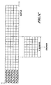
FIGURE 1A illustrates board coordinates, showing the main axis (X) along the nominal grain angle direction. -
FIGURE 1B illustrates a board divided into a 3-dimentional grid of discrete elements, showing index notation for different directions. -
FIGURE 1C illustrates a board divided into a 2-dimentional grid of discrete elements, showing notation of clear wood equivalent elements eij and a section of length W taken from it to estimate strength assigned a location in the center of the section. -
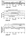
FIGURE 1D shows an example of a density and clear wood equivalent profile for a virtual detector (pixels of the same index j) along the board main axis X. The upper-most graph (with peaks pointing upwards) show actual density profile with its reference density profile below. The density peaks correspond to knots. The lower-most profile (with peaks pointing downwards) shows clear wood equivalent density. -
FIGURE 1E shows an example of predicted tension and bending profiles along the board main axis X, showing the lowest point (minimum) computed from a moving section along the board main axis. -
FIGURE 1F shows an example of moment of inertia profile with a section of a board used to compute modulus of elasticity (MOE) for a given location where prediction of modulus of elasticity (MOE) is computed using moment of inertia within a section of length s that moves along the board main axis. -
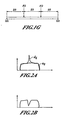
FIGURE 1G illustrates loading conditions assumed for computation of predicted modulus of elasticity (MOE) using moment of inertia within a section of length s. -
FIGURE 2A illustrates steps involved in clear wood density computing for a density cross-section showing original density dij and adaptive threshold aij. -
FIGURE 2B illustrates steps involved in clear wood density computing for a density cross-section, showing clear wood equivalent density eij. -
FIGURE 3 are linear and nonlinear models of a function reflecting effect of moisture content m(MC). -
FIGURE 3A is a moisture content prediction model showing predicted vs. oven-dry moisture content for southern yellow pine (SYP). -
FIGURE 4 illustrates a linear grading machine geometry, showing infeed wheel sets #1 and #2, outfeed wheel sets #1 and #2, and 3D-profile sensor. -
FIGURE 5 illustrates board behavior as the board passes through the linear grading machine. Characteristic points A, B, C, and D define different sections in the linear profile sensor profile corresponding to different support conditions of the board, wherein:- a) in
FIGURE 5A the board leading end is at point A - b) in
FIGURE 5B the board leading end is at point B - c) in
FIGURE 5C the board leading end is at point C - d) in
FIGURE 5D the board leading end is at point D.
- a) in
-
FIGURE 6 is continued board behavior as it passes through the linear grading machine having characteristic points E, F, and G and a board adjustment before and after the characteristic point F, wherein:- a) in
FIGURE 6A the board trailing end is at point E - b) in
FIGURE 6B the board trailing end is at point F - c) in
FIGURE 6C the board trailing end has passed point F - d) in
FIGURE 6D the board trailing end is at point G.
- a) in
-
FIGURE 7 is 3D-profile sensor profile segmented into different sections using characteristic points ofFIGURES 5A-D and 6A-D . - We have developed a machine to predict the strength and stiffness of wood based on a physical model using several sensing technologies. A physical model is an algorithm that relates the sensor information to the strength/stiffness of the material based on physical properties of the material and other characteristics, such as defects. The machine can integrate many sensing technologies into a single model and provides differing accuracy prediction based on the types and number of sensors used. In one embodiment, this technology builds on an X-ray based strength-grading machine, such as sold by Coe Newnes/McGehee ULC under the trademark XLG (X-ray Lumber Gauge).
- The following physical aspects of wood effect strength and stiffness of wood directly: wane, moisture content, Modulus of Elasticity including whether measured flatwise or edgewise, growth ring thickness or density (rings/inch), grain angle deviation, density, knots (location, density, type and size), location in the tree from which the wood was cut, fiber quality, such as mirofibril angle, juvenile wood, biodeterioration, etc., reaction wood species, manufacturing and drying defects, such as sawcuts, checks, shake, etc. and, size of actual cross-section.
- These wood aspects are measured or predicted with various sensing technologies and the data is used to predict the wood strength and stiffness. The reason to chose a physical model over other techniques such as a neural network, regression, or functional approximation model, is the stability and low training requirements. The model is based on the physical characteristics of the wood and how they affect the strength and stiffness directly rather than a statistical model. The sensor technologies added together improve the ability of any one sensor to predict strength and stiffness.
- The object is to have the predicted wood characteristics match the observed characteristics. The sensor technologies that can be used include but are not limited to the following: density map, moisture content, slope of grain map, growth ring measurements, dynamic wood bending for stiffness measurement, dynamic oscillation to determine stiffness, wood fiber quality determination (color vision, gray scale, infra-red, etc), determination of species, profile measurement, location wood is cut from in the tree, and mechanical wane propagation measurement.
- Combining some or all of these physical measurements, for example as combined according to the detailed methodology described below, leads to a better-predicted wood strength and stiffness accuracy.
- With respect to the following description then, it is to be realized that the optimum relationship between the components and steps of the invention, to include variations in method, components, materials, shape, form, function and manner of operation, assembly and use, are deemed readily apparent and obvious to one skilled in the art, and all equivalent relationships to those illustrated in the drawings and described in the specification are intended to be encompassed by the present invention.
- Clear wood equivalent (CWE) is used as an input to specific strength and stiffness models. Various prediction models may be used or developed based on this concept, such as prediction of ultimate tensile strength, modulus of rupture, etc. The CWE method approximates equivalent properties of a section of material in terms of density.
- Wood, in a coordinate system such as seen in
FIGURE 1A , is divided into a grid of virtual pixels (rectangular section) in the face plane or 3-dimensionally, as illustrated inFIGURE 1B . The size of the virtual pixels is configurable so as to be optimized. Initially a reference density from calibrated X-ray measurement is assigned to a pixel. Reference density is taken from density adaptive threshold. Following this, the initial density is modified by various wood characteristics, among which the most important is knot modification. The resulting density is equivalent to clear wood. In this context clear wood is defined as straight grained, defect-free, with a reference moisture content of 12%.FIGURE 1D shows an example of an actual density profile (ADP) along with its corresponding reference density profile (RDP) and corresponding clear wood equivalent (CWE) density profile along the main axis X. The equivalent to clear wood is then used directly for strength and stiffness using various algorithms, known relationships; etc. - Some of the following steps may be in used in clear wood equivalent density approximating of a virtual pixel:
- a) Start with reference density (adaptive threshold) at a virtual pixel.
- b) modify initial density for knots by considering presence of a knot in a location if the difference between the reference and actual density of the knot is non-zero.
- c) segment into regions so that a region contains a knot, use the segmented regions to recognize the knots region or regions.
- Different modification functions are used for the following knot types: sound through knot, sound edge knot, sound intermediate knot, loose through knot, loose edge knot, loose intermediate knot.
- Knot modification uses a concept of replacing a knot by its equivalent in terms of fiber strength or stiffness. This involves virtually removing the knot, computing remaining clear fiber volume, computing volume of the removed knot and adding the strength/stiffness equivalent of the knot to clear fibers. For every pixel density, dij, clear wood equivalent, eij, is computed using adaptive threshold aij (see
Figures 2a and 2b )
- Where,

i is virtual pixel index along wood length (virtual line index)
j is virtual pixel index across wood length (virtual detector index)
K is knot density ratio, defined as a ratio of Clear Wood Density to Knot Density and knot density is
KnotEquivalent is defined as clear wood density equivalent residing in knot volume,
- Where M is property (stiffness or strength) knot ratio

- The above relationships may be simplified to

or
- Grain angle is measured or estimated using one or more of the following techniques: microwave, optical, tracheid effect on face plane, 2D angle, tracheid effect on face plane and edges, 3D angle, growth ring pattern analysis with vision images (color or gray-scaled images), tracheid effect and growth ring pattern analysis with vision images. This algorithm accounts for the presence of a knot and grain deviation in the same location. Grain angle is decomposed into two components: local average, and, local deviation.
- Grain angle (GA) effect function for both average and the deviation, g(GA), reflects the relationship of grain angle vs. strength (or stiffness). This is derived from Hankinson's formula (Bodic 1982),

where n, m, are empirical constants, initially n = m = 2, (optimized).
R is the ratio between the property of interest (strength or stiffness) parallel to perpendicular to the grain. - Constants R, n, and m are to be optimized, with a restriction that the g(GA=0) = 1 and 1 ≥ g(GA) > 0 for any GA. Modification function g(GA) is applied to CWE density by multiplication of

- In case of grain deviation, g(GA) is further modified to account for a knot in the same location to eliminate a multiple CWE density reduction

- Where, T is a threshold value in terms of density.
- Important to the property of this relationship is if kij = T, then grain deviation modification has no effect:

- Both local average and local deviation are applied independently to CWE density.
- The moisture content effect function, m(MC), reflects the known effect of moisture content on strength or stiffness. This relationship is modeled as a linear (downward) for MC < MCsat =∼ 25%, and constant, m(MC) = msat, for MC >= MCsat. Ratio m(MCsat)/m(0) corresponds to the ratio between a property (MOE, MOR, UTS) at saturation to oven dry, P = Ssat/So. Based on literature, this ration is about 0.5 for UTS and MOR and 0.7 for MOE. Since the basis for our computations is property at MC = 12% then m(12%) = 1.0.
- Therefore the requirements for the m(MC) are:
- a. MC effect function is linear with a negative slope in the MC range from zero to saturation, and constant afterwards,

- b. Property ratio

- Initially,


- Solution for m(MC), linear model
- Solving equations (12) to (15), gives

and
- For example, for P = 0.5 and MCsat = 0.25,
A = 1.3158
B = 2.632
m(MCsat) = 0.6579 -
FIGURE 3 shows the linear model using the above constants and two nonlinear models:

-

- Where p() represents effect of pith on strength and stiffness.
-

- Where g () represents effect of growth ring thickness on strength and thickness
- Place within tree quality parameter is predicted based various scanning technologies

- Where t() is a function representing effect of position within tree.
- This set of modifications follow similarly to the modification analogues set out above for grain angle, moisture content, etc.
- This approach expands the two-dimensional CWE model as described above to three-dimensions (3D). Virtual pixels are defined in 3D. Knots, checks, and other defect modifications are done based on 3D-defect detection. Other multiple sided defects such as checks are also included. This includes two approaches:
- a) Density collected in 2D, knots, checks modifications entered as 3D, resulting with 3D grid of clear wood equivalent density
- b) Density collected in 3D with a CT scanner, knots, checks, and other 3D-defect modifications entered as 3D objects, resulting with 3D grid of clear wood equivalent density.
- This approach follows the one of CWE density described to this point, but the density is replaced with grain angle. First a grain angle is assigned to a grid element. Then the GA is modified by density, knots, moisture content, and other defects. Grain angle CWE is then used in actual models to predict strength and stiffness. This refers primary to lumber grading, but is not limited to this type of products.
- Stiffness (Modulus of Elasticity) is predicted based on approximated cross sectional moment of inertia Ji computed from clear wood equivalent model.
- In general, moment of inertia I is defined in x direction for any cross-section with an area A (Popov 1968)

- Where c is center of gravity of the cross-section A.
- In our case, I is approximated by Ji in terms of density, reflecting both geometry of the cross-section as well as local stiffness

- Where Δx represents pixel increment in x-axis direction and center of gravity is given as

- To increase processing speed, ci does not have to be computed for every cross-section, but assumed to be equal to nominal center of the cross-section.
- Two different approaches are given here to compute MOE from the Ji profile. In both cases MOE is computed on a section of Ji profile. The section is then moved along the board main axis X and MOE computed for another section of the board, as illustrated in
FIGURE 1F . This procedure yields a MOE profile along the main axis X. - First, a simple solution is given where MOE is simply weighted average of the Ji

- Where W j is optimized windowing (sectioning) function.
- Although, the equation (24) provides a simply and fast way of MOE prediction, a more sound but slower approach is to derive MOE directly from moment of inertia I. Following derivation follows well-known theory of mechanical behavior of solids (Popov 1968).
- Moment of inertia is assumed to be a variable quantity within a span s, as shown in
FIGURE 1F . For a board section loaded with force F, as inFIGURE 1G , equations for moments are


- The basic equation for beam deflection is

- Where E(x) represent MOE in location x,
I(x) moment of inertia profile,
V(x) deflection profile. - A further simplification combines E and I into one quantity J(x), which reflect a local stiffness of the cross-section.

- The equation (24e) simplifies into

- Following, the equation (24g) is solved for deflection Vmax at x = s/2 using direct integration method, applying boundary conditions, and converting to discrete format gives

- Where Δx in a discrete increment in direction of the X axis,

wi is discrete representation of w(x), - Ji is discrete representation of J(x), the moment of inertia estimation computed from clear wood equivalent density.
- On the other hand, for a uniform beam with loading conditions as in
FIGURE 1g , the solution for E is
or for the same cross-section and span (24j) simplifies to
- Where D is a constant representing a size of a board cross-section.
- Therefore a quantity to estimate is
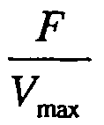
- This, compared with the solution (24h), yields final MOE estimation Eest

- Strength is predicted lengthwise for a section (window) along nominal main board axis X (nominal grain direction). Therefore a particular predicted strength is assigned to a center of a window lengthwise, as shown in
FIGURE 1E . These sections may overlap resulting with a complete strength profile for a wood product, such as lumber. Window length correspond to approximate size of typical wood fracture and generally increases with lumber width size (greater width size, greater the window). The final strength value assigned to a tested product is minimum strength within the strength profile. - Strength is computed on the basis of a running window along wood main axis (length), as illustrated in
FIGURE 1C , involving following steps: - a) get minimum CWE within a longitudinal slice,


Where i is pixel index within window, i = 0... W-1
and W is window size in virtual lines - b) compute overall CWE density for the window as a weighted sum

- Where wj is cross-sectional weight, greater at wood edges and less in the middle. The weight function is different for UTS and MOR and in general subject to model optimization.
- c) computes trength from CWE density tension strength (UTS) relationship

- And bending strength (MOR)

where fUTS and fMOR are optimized relationships between CWE and UTS and MOR. - The density to tension and bending strength functions are based on experimental data conducted on clear wood specimens and/or are in general the subject of model optimization.
- In particular, the following model may be used

and
where A, p, B, r are empirical (optimized) constants. - Moisture content is predicted based on microwave and/or X-ray density, for:
- (a) Microwave amplitude, and in particular: amplitude when microwave is polarized in transverse direction, amplitude when microwave is polarized in longitudinal direction, in form

where K and n are empirical constants, and a is microwave amplitude. - (b) Microwave amplitude and X-ray density, and in particular, amplitude when microwave is polarized in transverse direction and X-ray density, amplitude when microwave is polarized in longitudinal direction and X-ray density, in form:

where K, m, and n are empirical constants, a is microwave amplitude, and d is X-ray density. - Most models described here require optimization of the parameters (constants). Initial values for these parameters are taken from literature, using known relationships or from empirical data. Fine-tuning of these values for a specific species/size involves parameter optimization for maximum correlation with actual strength or stiffness, minimum prediction error, etc.
- Any method for multidimensional function optimization may be used, including genetic algorithms, random walk, and similar techniques, Powell's methods, and Gradient methods.
- Models may be optimized for:
- a) All sizes and species,
- b) Same sizes of the same species or species group, and
- c) Particular size and species.
- Vibration of a wood piece as it passes through a
grading machine 10 is used to estimate stiffness (MOE). Vibration profile may be collected with a laser/camera scanner, here referred to as a 3D sensor. Vibration is induced by machine feeding mechanics. - As wood behavior is linked with machine geometry and its position, the 3D-profile is segmented into different sections limited with characteristic points.
- A simplified grading machine geometry is show in
FIGURE 4 . Wheel sets 11, 12, 13, and 14 follow the direction of the lumber flow X'. -
Wood piece 15 enters the machine from right to left, passing through wheel sets 11 and 12 and into the field of view of3D 15 sensor as shown inFigures 4 and 5A-D . First collected profile point is at characteristic point A in the field of view ofsensor 15. From point A until the wood meets infeed guide 13a (characteristic point B), the leading end of the wood piece is fully unconstrained or free. This defines a first 3D profile section, AB. Following on downstream in direction X ' as seen inFigures 6a-6d , more characteristic points are defined as follows, where, at point: - C the leading end of
wood 15 meetswheel set 13 - D the leading end of
wood 15 meetswheel set 14 - E the trailing end of
wood 15 leaves wheel set 11 - F the trailing end of
wood 15 leaves wheel set 12 - G the trailing end of
wood 15 leaves3D sensor 16 and sections, - AC unconstrained
- CD semi-constrained
- DE fully-constrained
- EF semi-constrained
- FG unconstrained.
- From
Figures 5a-5d and6a-6d , it may be noted that only sections AB (or AC) and FG is statically undistorted by the machine. Because of unconstrained conditions, a free vibration takes place in these sections. - For the "S-shaped" wood in
Figures 6A-D , one could expect a wood behavior, resulting with the following 3D profile: - a. In section AC (or AB) unconstrained, Z is less than the reference (base) line X", and free vibrations with large amplitude take place. The frequency of vibration decreases because of increasing span.
- b. As the wood passed through characteristic point B or C, it is adjusted up, resulting with Z values greater than reference in semi-constrained section CD. Vibration amplitude in this section is somewhat reduced and higher in frequncy than in section AB.
- c. In fully-constrained section DE, wood behavior is somewhat undefined. However because of the constrained condition, reduced amplitude and increased frequency is expected.
- The scenario of wood behavior and a resulting 3D profile is put to the test by segmenting the profile into sections using characteristic points and comparing the expectations with the actual wood shape.
Figure 7 shows the 3D profile ofFIGURE 5A-D and6A-D with characteristic points and trend lines for every section. The characteristic points were defined based on machine geometry. For example, the distance between point A and C correspond to the distance between3D sensor 16 and center of the wheel set 13. Points A, B, C, and D were measured in reference to the start of 3D-profile sensor profile whereas points G, F, and E were measured in reference to the end of the 3D-profile. - Visual examination of the segmented profile in
Figure 7 confirms presence of distinct sections in the signal. Expected frequency and amplitude of unconstrained sections AB and FG, adjustments as points B, (or C), and F, and relatively leveled fully constrained section DE are confirmed. - Assuming a uniform cantilevered beam model, the lowest mode of vibration will have frequency

Where
Pi=3.14
E is elastic modulus
a is the span
I wood cross-sectional moment of inertia
m is distributed mass. - Frequency therefore is strongly affected by the span, as f is proportional to 1/a2. Because span changes as the wood passes through the machine, the vibration frequency decreases in the start section (AB) and increases in end section (FG). This explains 3D signals at the wood start and the end shown in
Figures 5A-D . This equation may be used for stiffness extraction. - Frequency for the semi-constrained and full-constrained conditions will have a more complex solution. However, the general relationship to E, I, and m, is similar, and sufficient to construct E (MOE) prediction model in general form.

where K is a constant than contains effect of type of constraint as well as span a effect. I is constant for a particular lumber size and m could be also assumed constant or measured, with X-ray for example.
Claims (18)
- A method of predicting strength and stiffness of a wood piece, the method comprising:a) Measuring the wood piece with a multiplicity of sensors, each of said sensors outputting measurement data;b) Estimating, based on said measurement data, a characteristic including one or more of the following: clear wood density, grain angle, moisture content, growth ring angle, location in the tree from which the wood was cut, size of actual cross-section, species, and three dimensional geometry, wherein said estimating further includes estimating a fiber quality, the fiber quality being at least one of microfibril angle, juvenile wood, biodeterioration, and reaction wood;c) Detecting a size, location and classification of a wood defect including one or more of the following: knots, biodeterioration, reaction wood, juvenile wood, manufacturing and drying defects, pith, pitch and wet pockets, wherein said manufacturing and drying defects comprise at least one of sawcuts, checks, and shake;d) Subsequently inputting information from said measuring, estimating and detecting steps into a physical model of the wood piece;e) Characterized in that said physical model of wood piece is constructed based on clear wood equivalent (CWE) by approximating equivalent properties of a section of the wood piece divided into a grid of virtual pixels, measuring and assigning a reference density or grain angle to each pixel and modifying the reference density or grain angle of each pixel for defects including one or more of the following: knots, biodeterioration, reaction wood, juvenile wood, manufacturing and drying defects, pith, pitch and wet pockets; andf) Predicting strength and stiffness of the wood piece based on the effect of said estimated information from said step of estimating said characteristic and said detected information from said step of detecting a defect on mechanical behavior of the wood piece.
- The method of claim 1 wherein said measuring comprises measuring material characteristics of the wood piece including one or more of the following: growth ring thickness; grain angle deviation; clear wood density; knot location; knot density; knot type; knot size; location in the tree from which the wood piece was cut.
- The method of claim 1 further including calculating a clear wood density equivalent, said calculating comprising:a) Measuring material density in a plurality of dimensions;b) Estimating the characteristic and the fiber quality;c) Reducing clear wood equivalent density by the effect of the characteristic and the fiber quality on mechanical behavior of wood;d) Detecting size, location and classification of the defect; ande) Further reducing clear wood equivalent density by the effect of the defect on mechanical behavior of wood.
- The method of claim 1 further including calculating a clear zero grain angle wood equivalent, the calculating comprisinga) Measuring of grain angle in a plurality of dimensions;b) Constructing clear wood zero grain angle equivalent by assigning a nominal density value which is an average for a wood species whenever grain angle relative to a longitudinal axis of the piece is zero, and less wherever the grain angle deviates from zero and accordingly to grain angle effect on mechanical behavior of the wood piece;c) Reducing clear wood equivalent density by the effect of the characteristic using theoretical and empirical relationships of the characteristic on mechanical behavior of wood; andd) Further reducing clear wood equivalent density by the effect of wood defects in their respective locations of occurrence and the effect on mechanical behavior of the wood piece.
- The method of claim 3 or 4 further comprising dividing the wood piece into a grid of virtual pixels, virtually removing density occupied by a knot, and replacing said virtually removed density by a density of clear wood mechanically equivalent to the removed knot.
- The method of claim 3 wherein said calculating a clear wood density equivalent is applied to a limited section of the wood piece, and wherein the limited section is translated along the grain direction axis of the wood piece.
- The method of claim 1 further including estimating bending and tension strength of at least a portion of the length of the wood piece by determining a minimum of a lengthwise strength profile of the wood piece.
- The method of claim 1 wherein said collecting information relating to fiber quality includes measuring a vibration frequency of the wood piece, wherein said vibration frequency is a result of vibration induced only by feeding of the wood piece in an infeed feeding the wood piece to the sensors and without any explicit vibration-inducing impact means.
- The method of claim 7 further comprising estimating bending and tension strength of the wood piece by measuring a vibration frequency of the wood piece wherein said vibration frequency is a result of vibration induced only by feeding of the wood piece in an infeed feeding the wood piece to the sensors and without any explicit vibration-inducing impact means.
- The method of claim 9 further comprising measuring said vibration signal by dividing the vibration signal into different sections corresponding to the support and constraint conditions of the wood piece on the infeed or the outfeed rolls.
- The method of claim 2 wherein said material characteristics comprise at least one of clear wood density or knot density, and wherein said at least one is measured by a scanner using a radiation source.
- The method of claim 1 wherein said moisture content is estimated using microwave measurement.
- The method of claim 12 wherein said microwave measurement is measured when an applied microwave radiation is polarized in a direction transverse to a longitudinal axis of the wood piece.
- The method of claim 12 wherein microwave measurement is corrected for temperature.
- The method of claim 1 wherein said moisture content is estimated using X-ray measurement.
- The method of claim 1 wherein said predicting of stiffness of the wood piece is based on Moment of Inertia.
- The method of claim 5 further including creating a three-dimensional (3D) wood equivalent model by dividing said grid of virtual pixels in three dimensions.
- The method of claim 1 wherein said physical model is optimized by fine-tuning the initial values of the parameters for maximum correlation with actual strength or stiffness.
Applications Claiming Priority (2)
| Application Number | Priority Date | Filing Date | Title |
|---|---|---|---|
| US47338503P | 2003-05-27 | 2003-05-27 | |
| PCT/US2004/016589 WO2004106918A1 (en) | 2003-05-27 | 2004-05-26 | Method of wood strength and stiffness prediction |
Publications (3)
| Publication Number | Publication Date |
|---|---|
| EP1634070A1 EP1634070A1 (en) | 2006-03-15 |
| EP1634070B1 true EP1634070B1 (en) | 2011-10-05 |
| EP1634070B9 EP1634070B9 (en) | 2012-05-09 |
Family
ID=33490598
Family Applications (1)
| Application Number | Title | Priority Date | Filing Date |
|---|---|---|---|
| EP04753419A Expired - Lifetime EP1634070B9 (en) | 2003-05-27 | 2004-05-26 | Method of wood strength and stiffness prediction |
Country Status (7)
| Country | Link |
|---|---|
| US (1) | US7680304B2 (en) |
| EP (1) | EP1634070B9 (en) |
| AT (1) | ATE527541T1 (en) |
| AU (1) | AU2004243873B2 (en) |
| CA (2) | CA2530919C (en) |
| NZ (1) | NZ544435A (en) |
| WO (1) | WO2004106918A1 (en) |
Families Citing this family (34)
| Publication number | Priority date | Publication date | Assignee | Title |
|---|---|---|---|---|
| US7149633B2 (en) | 2004-02-26 | 2006-12-12 | Coe Newnes/Mcgettee Inc. | Displacement method of knot sizing |
| US20070263918A1 (en) * | 2006-02-13 | 2007-11-15 | David Jenya | Method and system of recognizing profiles and defects in wood processing |
| US8662121B2 (en) * | 2006-03-30 | 2014-03-04 | Weyerhaeuser Nr Company | Method for reducing warp potential within lumber derived from a raw material |
| US7938156B2 (en) * | 2006-04-20 | 2011-05-10 | Weyerhaeuser Nr Company | Method for optimizing lumber |
| US7679752B2 (en) * | 2006-09-27 | 2010-03-16 | Weyerhaeuser Nr Company | Methods for detecting pitch in lumber |
| US7676953B2 (en) * | 2006-12-29 | 2010-03-16 | Signature Control Systems, Inc. | Calibration and metering methods for wood kiln moisture measurement |
| EP1950561A1 (en) * | 2007-01-29 | 2008-07-30 | LuxScan Technologies SARL | Contactless control of the stiffness of wood products in the production line |
| US7900663B2 (en) * | 2007-03-28 | 2011-03-08 | Weyerhaeuser Nr Company | Method for grading a wood sample based on pith direction and/or pith location |
| US7684030B2 (en) | 2007-05-04 | 2010-03-23 | Vab Solutions Inc. | Enclosure for a linear inspection system |
| US8060835B2 (en) * | 2007-06-05 | 2011-11-15 | The Boeing Company | Three dimensional defect mapping |
| US8266073B2 (en) * | 2008-10-02 | 2012-09-11 | Wagner Electronic Products, Inc. | System for maximizing a value of lumber |
| US8073192B2 (en) * | 2008-12-24 | 2011-12-06 | Weyerhaeuser Nr Company | Determining wood characteristics using annual ring images from lumber faces |
| DE102009002818B4 (en) * | 2009-05-05 | 2022-02-10 | Axel Meyer | Method and device for testing the stability of a mast |
| US8434232B2 (en) * | 2009-06-26 | 2013-05-07 | Weyerhaeuser Nr Company | Method for constructing a truss from selected components |
| EP2295963B1 (en) * | 2009-09-11 | 2013-12-25 | MICROTEC S.r.l. | Method and apparatus for determining the knot-to-volume ratio of wooden planks |
| IT1398908B1 (en) * | 2010-03-03 | 2013-03-21 | Microtec Srl | METHOD AND EQUIPMENT FOR THE DETERMINATION OF THE FREQUENCY BELOW FOR WOODEN TABLES |
| ES2381723B1 (en) | 2010-04-12 | 2013-04-26 | Asociacion De Investigacion Y Desarrollo En La Industria Del Mueble Y Afines (Aidima) | ARTIFICIAL VISION SYSTEM FOR DETECTION OF DEFECTS IN FINISHED SURFACES |
| FR2967492B1 (en) | 2010-11-17 | 2013-03-01 | Innodura | METHOD AND DEVICE FOR NON-DESTRUCTIVE DETERMINATION OF THE BREAKING MODULE OF A WOODEN PIECE |
| US20130173179A1 (en) * | 2011-12-30 | 2013-07-04 | Weyerhaeuser Nr Company | Method for predicting whether a wood product originated from a butt log |
| US10346962B2 (en) | 2012-02-10 | 2019-07-09 | Corning Incorporated | Nondestructive method to predict isostatic strength in ceramic substrates |
| SE536623C2 (en) * | 2012-03-08 | 2014-04-08 | Innovation Vision Ab | Method and apparatus for evaluating a wooden board |
| CN106651831B (en) * | 2016-09-30 | 2020-02-11 | 广西师范大学 | Bamboo block defect detection method and system |
| CN106683093B (en) * | 2017-01-12 | 2019-11-29 | 国家林业和草原局北京林业机械研究所 | Plate presentation quality Comprehensive quantitative evaluation method |
| WO2018169712A1 (en) * | 2017-03-13 | 2018-09-20 | Lucidyne Technologies, Inc. | Method of board lumber grading using deep learning techniques |
| CN109254017B (en) * | 2017-07-15 | 2021-05-07 | 杭州峙汇科技有限公司 | Tree internal defect detector |
| CN111400956B (en) * | 2020-03-31 | 2023-07-14 | 杨雨厚 | Corner-based beam member equivalent bending stiffness testing method |
| CN111624114B (en) * | 2020-06-05 | 2023-06-16 | 内蒙古农业大学 | A method for evaluating wood physical and mechanical properties based on wood micro-morphological characteristics |
| CN114252347B (en) * | 2021-12-21 | 2022-10-18 | 江苏楚汉新型建材有限公司 | Wood bending strength determination method and system based on image processing |
| CN114993880B (en) * | 2022-05-16 | 2024-11-22 | 华南农业大学 | A method and system for quickly calculating the moisture content distribution of wood fiber materials |
| CN115372200A (en) * | 2022-07-12 | 2022-11-22 | 蓝冰河(常州)精密测量技术有限责任公司 | On-line surface density measurement method and device based on X-ray |
| US12327344B2 (en) * | 2022-08-31 | 2025-06-10 | The Boeing Company | Natural feature pick and place system for composite materials |
| CN118364294B (en) * | 2024-06-14 | 2024-11-01 | 深圳市同方电子新材料有限公司 | Multi-factor-based intelligent detection method and system for tensile strength of soldering tin bar |
| CN119887923B (en) * | 2025-01-07 | 2025-07-22 | 威海北港电器有限公司 | A visual precision positioning system for wood splitters |
| CN119446370B (en) * | 2025-01-09 | 2025-05-09 | 山东科技大学 | A method and system for predicting asphalt mixture strength based on discrete element method simulation |
Family Cites Families (14)
| Publication number | Priority date | Publication date | Assignee | Title |
|---|---|---|---|---|
| FI57490C (en) | 1978-06-01 | 1980-08-11 | Innotec Oy | FOERFARANDE FOER BESTAEMNING AV SNEDFIBRIGHETEN I VIRKE I SYNNERHET I SAOGAT VIRKE |
| US5024091A (en) | 1986-03-25 | 1991-06-18 | Washington State University Research Foundation, Inc. | Non-destructive evaluation of structural members |
| US4926350A (en) * | 1987-09-14 | 1990-05-15 | Metriguard, Inc. | Non-destructive testing methods for lumber |
| US4941357A (en) | 1988-12-23 | 1990-07-17 | Weyerhaeuser Company | Method for estimating the strength of wood |
| US5394097A (en) * | 1992-11-24 | 1995-02-28 | Bechtel; Friend K. | Dielectric sensor |
| US5804728A (en) | 1994-09-07 | 1998-09-08 | The Regents Of The University Of California | Method and apparatus for non-intrusively detecting hidden defects caused by bio-deterioration in living trees and round wood materials |
| US5960104A (en) | 1996-08-16 | 1999-09-28 | Virginia Polytechnic & State University | Defect detection system for lumber |
| US6773552B1 (en) | 1998-08-24 | 2004-08-10 | Carter Holt Harvey Limited | Method of selecting and/or processing wood according to fibre characteristics |
| US6769306B2 (en) * | 1998-12-17 | 2004-08-03 | Carter Holt Harvey Limited | Log cutting procedures |
| WO2001009603A1 (en) * | 1999-07-30 | 2001-02-08 | Carter Holt Harvey Limited | Log testing apparatus |
| WO2001065253A2 (en) | 2000-02-29 | 2001-09-07 | Mercure Innovation (Sarl) | Non-destructive method for controlling wooden poles in particular electrical or telephone network poles |
| US20020025061A1 (en) | 2000-08-23 | 2002-02-28 | Leonard Metcalfe | High speed and reliable determination of lumber quality using grain influenced distortion effects |
| EP1410050A1 (en) * | 2001-06-15 | 2004-04-21 | Mississippi State University | Through-log density detector |
| US7047156B1 (en) * | 2002-12-14 | 2006-05-16 | Kierstat Systems Llc | Method for estimating compliance at points along a beam from bending measurements |
-
2004
- 2004-05-25 US US10/854,930 patent/US7680304B2/en active Active
- 2004-05-26 WO PCT/US2004/016589 patent/WO2004106918A1/en not_active Ceased
- 2004-05-26 CA CA2530919A patent/CA2530919C/en not_active Expired - Fee Related
- 2004-05-26 EP EP04753419A patent/EP1634070B9/en not_active Expired - Lifetime
- 2004-05-26 NZ NZ544435A patent/NZ544435A/en not_active IP Right Cessation
- 2004-05-26 AT AT04753419T patent/ATE527541T1/en not_active IP Right Cessation
- 2004-05-26 CA CA2917094A patent/CA2917094C/en not_active Expired - Fee Related
- 2004-05-26 AU AU2004243873A patent/AU2004243873B2/en not_active Ceased
Also Published As
| Publication number | Publication date |
|---|---|
| ATE527541T1 (en) | 2011-10-15 |
| US7680304B2 (en) | 2010-03-16 |
| CA2530919A1 (en) | 2004-12-09 |
| AU2004243873B2 (en) | 2009-11-19 |
| US20050031158A1 (en) | 2005-02-10 |
| WO2004106918A1 (en) | 2004-12-09 |
| CA2917094A1 (en) | 2004-12-09 |
| EP1634070A1 (en) | 2006-03-15 |
| CA2530919C (en) | 2017-12-19 |
| AU2004243873A1 (en) | 2004-12-09 |
| CA2917094C (en) | 2018-03-27 |
| NZ544435A (en) | 2007-05-31 |
| EP1634070B9 (en) | 2012-05-09 |
Similar Documents
| Publication | Publication Date | Title |
|---|---|---|
| EP1634070B9 (en) | Method of wood strength and stiffness prediction | |
| Viguier et al. | Modelling mechanical properties of spruce and Douglas fir timber by means of X-ray and grain angle measurements for strength grading purpose | |
| US7324904B2 (en) | Methods for determining dimensional stability of wood products utilizing single and multiple sensor groups | |
| US7584652B2 (en) | Methods of rapidly simulating in-service warp distortion of a wood product and/or rapidly estimating shrinkage properties using electromagnetic energy | |
| Kandler et al. | Effective stiffness prediction of GLT beams based on stiffness distributions of individual lamellas | |
| Kandler et al. | Experimental study on glued laminated timber beams with well-known knot morphology | |
| US7286956B2 (en) | Methods of estimating the dimensional stability of a wood product from simple algebraic functions of moisture, shrinkage rates and grain angles | |
| Lukacevic et al. | Discussion of common and new indicating properties for the strength grading of wooden boards | |
| CA2583975C (en) | Method for optimizing lumber | |
| EP1978359A1 (en) | Methods for predicting warp at a given condition | |
| Ehrhart et al. | Predicting the strength of European beech (Fagus sylvatica L.) boards using image-based local fibre direction data | |
| US7149633B2 (en) | Displacement method of knot sizing | |
| Dahlen et al. | Near-infrared spectroscopy prediction of southern pine No. 2 lumber physical and mechanical properties | |
| Hu et al. | ASSESSMENT OF A THREE DIMENSIONAL FIBRE ORIENTATION MODEL FOR TIMBER | |
| Pereira et al. | A probabilistic approach to the evaluation of the bending strength of timber beams with integration of data from on-site tests | |
| EP3798908B1 (en) | Computer-implemented method for training or using a software infrastructure based on machine-learning techniques | |
| EP2823298B1 (en) | Method and device for evaluating a wooden board | |
| BOURREAU et al. | Modelling mechanical properties of spruce and Douglas fir timber by means of X-ray and grain angle measurements for strength grading purpose | |
| Penvern et al. | Comparison of various internal fibre orientation determination methods for predicting the mechanical properties of one Douglas-fir timber board | |
| JEHL et al. | Improving strength grading of lumber by grain angle measurement and mechanical modeling | |
| Level | MOE and MOR assessment technologies for improving graded recovery of exotic pines in Australia | |
| Oh et al. | Development of a Method to Predict the Bending Strength of Lumber Without Regard to Species Using X-ray Images | |
| Wang et al. | USING STATIC TEST DATA AND CHANGES IN FREQUENCIES |
Legal Events
| Date | Code | Title | Description |
|---|---|---|---|
| PUAI | Public reference made under article 153(3) epc to a published international application that has entered the european phase |
Free format text: ORIGINAL CODE: 0009012 |
|
| 17P | Request for examination filed |
Effective date: 20051222 |
|
| AK | Designated contracting states |
Kind code of ref document: A1 Designated state(s): AT BE BG CH CY CZ DE DK EE ES FI FR GB GR HU IE IT LI LU MC NL PL PT RO SE SI SK TR |
|
| AX | Request for extension of the european patent |
Extension state: AL HR LT LV MK |
|
| RIN1 | Information on inventor provided before grant (corrected) |
Inventor name: BIERNACKI, JACEK Inventor name: WOODS, STEVE Inventor name: LAHODA, RON Inventor name: FLATMAN, CARL |
|
| 17Q | First examination report despatched |
Effective date: 20080320 |
|
| GRAP | Despatch of communication of intention to grant a patent |
Free format text: ORIGINAL CODE: EPIDOSNIGR1 |
|
| GRAS | Grant fee paid |
Free format text: ORIGINAL CODE: EPIDOSNIGR3 |
|
| GRAA | (expected) grant |
Free format text: ORIGINAL CODE: 0009210 |
|
| RIN1 | Information on inventor provided before grant (corrected) |
Inventor name: LAHODA, RON Inventor name: WOODS, STEVE Inventor name: FLATMAN, CARL Inventor name: BIERNACKI, JACEK |
|
| AK | Designated contracting states |
Kind code of ref document: B1 Designated state(s): AT BE BG CH CY CZ DE DK EE ES FI FR GB GR HU IE IT LI LU MC NL PL PT RO SE SI SK TR |
|
| AX | Request for extension of the european patent |
Extension state: AL HR LT LV MK |
|
| REG | Reference to a national code |
Ref country code: GB Ref legal event code: FG4D |
|
| REG | Reference to a national code |
Ref country code: CH Ref legal event code: EP |
|
| RAP2 | Party data changed (patent owner data changed or rights of a patent transferred) |
Owner name: USNR/KOCKUMS CANCAR COMPANY |
|
| REG | Reference to a national code |
Ref country code: IE Ref legal event code: FG4D |
|
| REG | Reference to a national code |
Ref country code: DE Ref legal event code: R096 Ref document number: 602004034698 Country of ref document: DE Effective date: 20111208 |
|
| REG | Reference to a national code |
Ref country code: SE Ref legal event code: TRGR |
|
| REG | Reference to a national code |
Ref country code: NL Ref legal event code: VDEP Effective date: 20111005 |
|
| PG25 | Lapsed in a contracting state [announced via postgrant information from national office to epo] |
Ref country code: SI Free format text: LAPSE BECAUSE OF FAILURE TO SUBMIT A TRANSLATION OF THE DESCRIPTION OR TO PAY THE FEE WITHIN THE PRESCRIBED TIME-LIMIT Effective date: 20111005 |
|
| LTIE | Lt: invalidation of european patent or patent extension |
Effective date: 20111005 |
|
| REG | Reference to a national code |
Ref country code: DE Ref legal event code: R082 Ref document number: 602004034698 Country of ref document: DE Representative=s name: LEDERER & KELLER, DE |
|
| REG | Reference to a national code |
Ref country code: AT Ref legal event code: MK05 Ref document number: 527541 Country of ref document: AT Kind code of ref document: T Effective date: 20111005 |
|
| PG25 | Lapsed in a contracting state [announced via postgrant information from national office to epo] |
Ref country code: BE Free format text: LAPSE BECAUSE OF FAILURE TO SUBMIT A TRANSLATION OF THE DESCRIPTION OR TO PAY THE FEE WITHIN THE PRESCRIBED TIME-LIMIT Effective date: 20111005 |
|
| REG | Reference to a national code |
Ref country code: DE Ref legal event code: R082 Ref document number: 602004034698 Country of ref document: DE Representative=s name: LEDERER & KELLER, DE Effective date: 20120330 Ref country code: DE Ref legal event code: R081 Ref document number: 602004034698 Country of ref document: DE Owner name: USNR/KOCKUMS CANCAR CO., US Free format text: FORMER OWNER: COE NEWNES/MCGEHEE INC., SALMON ARM, CA Effective date: 20120330 Ref country code: DE Ref legal event code: R081 Ref document number: 602004034698 Country of ref document: DE Owner name: USNR/KOCKUMS CANCAR CO., US Free format text: FORMER OWNER: COE NEWNES/MCGEHEE INC., SALMON ARM, CA Effective date: 20111017 Ref country code: DE Ref legal event code: R082 Ref document number: 602004034698 Country of ref document: DE Representative=s name: LEDERER & KELLER PATENTANWAELTE PARTNERSCHAFT , DE Effective date: 20120330 Ref country code: DE Ref legal event code: R081 Ref document number: 602004034698 Country of ref document: DE Owner name: USNR/KOCKUMS CANCAR CO., VANCOUVER, US Free format text: FORMER OWNER: COE NEWNES/MCGEHEE INC., SALMON ARM, CA Effective date: 20120330 Ref country code: DE Ref legal event code: R081 Ref document number: 602004034698 Country of ref document: DE Owner name: USNR/KOCKUMS CANCAR CO., VANCOUVER, US Free format text: FORMER OWNER: COE NEWNES/MCGEHEE INC., SALMON ARM, CA Effective date: 20111017 |
|
| PG25 | Lapsed in a contracting state [announced via postgrant information from national office to epo] |
Ref country code: NL Free format text: LAPSE BECAUSE OF FAILURE TO SUBMIT A TRANSLATION OF THE DESCRIPTION OR TO PAY THE FEE WITHIN THE PRESCRIBED TIME-LIMIT Effective date: 20111005 Ref country code: PT Free format text: LAPSE BECAUSE OF FAILURE TO SUBMIT A TRANSLATION OF THE DESCRIPTION OR TO PAY THE FEE WITHIN THE PRESCRIBED TIME-LIMIT Effective date: 20120206 Ref country code: GR Free format text: LAPSE BECAUSE OF FAILURE TO SUBMIT A TRANSLATION OF THE DESCRIPTION OR TO PAY THE FEE WITHIN THE PRESCRIBED TIME-LIMIT Effective date: 20120106 |
|
| PG25 | Lapsed in a contracting state [announced via postgrant information from national office to epo] |
Ref country code: CY Free format text: LAPSE BECAUSE OF FAILURE TO SUBMIT A TRANSLATION OF THE DESCRIPTION OR TO PAY THE FEE WITHIN THE PRESCRIBED TIME-LIMIT Effective date: 20111005 |
|
| PG25 | Lapsed in a contracting state [announced via postgrant information from national office to epo] |
Ref country code: CZ Free format text: LAPSE BECAUSE OF FAILURE TO SUBMIT A TRANSLATION OF THE DESCRIPTION OR TO PAY THE FEE WITHIN THE PRESCRIBED TIME-LIMIT Effective date: 20111005 Ref country code: EE Free format text: LAPSE BECAUSE OF FAILURE TO SUBMIT A TRANSLATION OF THE DESCRIPTION OR TO PAY THE FEE WITHIN THE PRESCRIBED TIME-LIMIT Effective date: 20111005 Ref country code: BG Free format text: LAPSE BECAUSE OF FAILURE TO SUBMIT A TRANSLATION OF THE DESCRIPTION OR TO PAY THE FEE WITHIN THE PRESCRIBED TIME-LIMIT Effective date: 20120105 Ref country code: DK Free format text: LAPSE BECAUSE OF FAILURE TO SUBMIT A TRANSLATION OF THE DESCRIPTION OR TO PAY THE FEE WITHIN THE PRESCRIBED TIME-LIMIT Effective date: 20111005 Ref country code: SK Free format text: LAPSE BECAUSE OF FAILURE TO SUBMIT A TRANSLATION OF THE DESCRIPTION OR TO PAY THE FEE WITHIN THE PRESCRIBED TIME-LIMIT Effective date: 20111005 |
|
| PLBE | No opposition filed within time limit |
Free format text: ORIGINAL CODE: 0009261 |
|
| STAA | Information on the status of an ep patent application or granted ep patent |
Free format text: STATUS: NO OPPOSITION FILED WITHIN TIME LIMIT |
|
| PG25 | Lapsed in a contracting state [announced via postgrant information from national office to epo] |
Ref country code: PL Free format text: LAPSE BECAUSE OF FAILURE TO SUBMIT A TRANSLATION OF THE DESCRIPTION OR TO PAY THE FEE WITHIN THE PRESCRIBED TIME-LIMIT Effective date: 20111005 Ref country code: RO Free format text: LAPSE BECAUSE OF FAILURE TO SUBMIT A TRANSLATION OF THE DESCRIPTION OR TO PAY THE FEE WITHIN THE PRESCRIBED TIME-LIMIT Effective date: 20111005 |
|
| 26N | No opposition filed |
Effective date: 20120706 |
|
| REG | Reference to a national code |
Ref country code: DE Ref legal event code: R097 Ref document number: 602004034698 Country of ref document: DE Effective date: 20120706 |
|
| PG25 | Lapsed in a contracting state [announced via postgrant information from national office to epo] |
Ref country code: MC Free format text: LAPSE BECAUSE OF NON-PAYMENT OF DUE FEES Effective date: 20120531 |
|
| REG | Reference to a national code |
Ref country code: CH Ref legal event code: PL |
|
| PG25 | Lapsed in a contracting state [announced via postgrant information from national office to epo] |
Ref country code: CH Free format text: LAPSE BECAUSE OF NON-PAYMENT OF DUE FEES Effective date: 20120531 Ref country code: AT Free format text: LAPSE BECAUSE OF FAILURE TO SUBMIT A TRANSLATION OF THE DESCRIPTION OR TO PAY THE FEE WITHIN THE PRESCRIBED TIME-LIMIT Effective date: 20111005 Ref country code: LI Free format text: LAPSE BECAUSE OF NON-PAYMENT OF DUE FEES Effective date: 20120531 |
|
| REG | Reference to a national code |
Ref country code: IE Ref legal event code: MM4A |
|
| REG | Reference to a national code |
Ref country code: FR Ref legal event code: ST Effective date: 20130131 |
|
| PG25 | Lapsed in a contracting state [announced via postgrant information from national office to epo] |
Ref country code: ES Free format text: LAPSE BECAUSE OF FAILURE TO SUBMIT A TRANSLATION OF THE DESCRIPTION OR TO PAY THE FEE WITHIN THE PRESCRIBED TIME-LIMIT Effective date: 20120116 Ref country code: IE Free format text: LAPSE BECAUSE OF NON-PAYMENT OF DUE FEES Effective date: 20120526 Ref country code: FR Free format text: LAPSE BECAUSE OF NON-PAYMENT OF DUE FEES Effective date: 20120531 |
|
| PG25 | Lapsed in a contracting state [announced via postgrant information from national office to epo] |
Ref country code: TR Free format text: LAPSE BECAUSE OF FAILURE TO SUBMIT A TRANSLATION OF THE DESCRIPTION OR TO PAY THE FEE WITHIN THE PRESCRIBED TIME-LIMIT Effective date: 20111005 |
|
| PG25 | Lapsed in a contracting state [announced via postgrant information from national office to epo] |
Ref country code: LU Free format text: LAPSE BECAUSE OF NON-PAYMENT OF DUE FEES Effective date: 20120526 |
|
| PG25 | Lapsed in a contracting state [announced via postgrant information from national office to epo] |
Ref country code: HU Free format text: LAPSE BECAUSE OF FAILURE TO SUBMIT A TRANSLATION OF THE DESCRIPTION OR TO PAY THE FEE WITHIN THE PRESCRIBED TIME-LIMIT Effective date: 20040526 |
|
| PGFP | Annual fee paid to national office [announced via postgrant information from national office to epo] |
Ref country code: IT Payment date: 20210524 Year of fee payment: 18 Ref country code: DE Payment date: 20210527 Year of fee payment: 18 Ref country code: FI Payment date: 20210527 Year of fee payment: 18 |
|
| PGFP | Annual fee paid to national office [announced via postgrant information from national office to epo] |
Ref country code: GB Payment date: 20210527 Year of fee payment: 18 Ref country code: SE Payment date: 20210527 Year of fee payment: 18 |
|
| REG | Reference to a national code |
Ref country code: DE Ref legal event code: R119 Ref document number: 602004034698 Country of ref document: DE |
|
| REG | Reference to a national code |
Ref country code: SE Ref legal event code: EUG |
|
| GBPC | Gb: european patent ceased through non-payment of renewal fee |
Effective date: 20220526 |
|
| PG25 | Lapsed in a contracting state [announced via postgrant information from national office to epo] |
Ref country code: SE Free format text: LAPSE BECAUSE OF NON-PAYMENT OF DUE FEES Effective date: 20220527 Ref country code: FI Free format text: LAPSE BECAUSE OF NON-PAYMENT OF DUE FEES Effective date: 20220526 |
|
| PG25 | Lapsed in a contracting state [announced via postgrant information from national office to epo] |
Ref country code: GB Free format text: LAPSE BECAUSE OF NON-PAYMENT OF DUE FEES Effective date: 20220526 Ref country code: DE Free format text: LAPSE BECAUSE OF NON-PAYMENT OF DUE FEES Effective date: 20221201 |
|
| PG25 | Lapsed in a contracting state [announced via postgrant information from national office to epo] |
Ref country code: IT Free format text: LAPSE BECAUSE OF NON-PAYMENT OF DUE FEES Effective date: 20220526 |