EP1633831B1 - Delayed coking process for producing free-flowing shot coke - Google Patents
Delayed coking process for producing free-flowing shot coke Download PDFInfo
- Publication number
- EP1633831B1 EP1633831B1 EP20040752350 EP04752350A EP1633831B1 EP 1633831 B1 EP1633831 B1 EP 1633831B1 EP 20040752350 EP20040752350 EP 20040752350 EP 04752350 A EP04752350 A EP 04752350A EP 1633831 B1 EP1633831 B1 EP 1633831B1
- Authority
- EP
- European Patent Office
- Prior art keywords
- coke
- mosaic
- resid
- shot
- additive
- Prior art date
- Legal status (The legal status is an assumption and is not a legal conclusion. Google has not performed a legal analysis and makes no representation as to the accuracy of the status listed.)
- Expired - Lifetime
Links
Images


Classifications
-
- C—CHEMISTRY; METALLURGY
- C10—PETROLEUM, GAS OR COKE INDUSTRIES; TECHNICAL GASES CONTAINING CARBON MONOXIDE; FUELS; LUBRICANTS; PEAT
- C10B—DESTRUCTIVE DISTILLATION OF CARBONACEOUS MATERIALS FOR PRODUCTION OF GAS, COKE, TAR, OR SIMILAR MATERIALS
- C10B57/00—Other carbonising or coking processes; Features of destructive distillation processes in general
- C10B57/04—Other carbonising or coking processes; Features of destructive distillation processes in general using charges of special composition
- C10B57/06—Other carbonising or coking processes; Features of destructive distillation processes in general using charges of special composition containing additives
-
- C—CHEMISTRY; METALLURGY
- C10—PETROLEUM, GAS OR COKE INDUSTRIES; TECHNICAL GASES CONTAINING CARBON MONOXIDE; FUELS; LUBRICANTS; PEAT
- C10B—DESTRUCTIVE DISTILLATION OF CARBONACEOUS MATERIALS FOR PRODUCTION OF GAS, COKE, TAR, OR SIMILAR MATERIALS
- C10B55/00—Coking mineral oils, bitumen, tar, and the like or mixtures thereof with solid carbonaceous material
-
- C—CHEMISTRY; METALLURGY
- C10—PETROLEUM, GAS OR COKE INDUSTRIES; TECHNICAL GASES CONTAINING CARBON MONOXIDE; FUELS; LUBRICANTS; PEAT
- C10G—CRACKING HYDROCARBON OILS; PRODUCTION OF LIQUID HYDROCARBON MIXTURES, e.g. BY DESTRUCTIVE HYDROGENATION, OLIGOMERISATION, POLYMERISATION; RECOVERY OF HYDROCARBON OILS FROM OIL-SHALE, OIL-SAND, OR GASES; REFINING MIXTURES MAINLY CONSISTING OF HYDROCARBONS; REFORMING OF NAPHTHA; MINERAL WAXES
- C10G2300/00—Aspects relating to hydrocarbon processing covered by groups C10G1/00 - C10G99/00
- C10G2300/10—Feedstock materials
- C10G2300/107—Atmospheric residues having a boiling point of at least about 538 °C
-
- C—CHEMISTRY; METALLURGY
- C10—PETROLEUM, GAS OR COKE INDUSTRIES; TECHNICAL GASES CONTAINING CARBON MONOXIDE; FUELS; LUBRICANTS; PEAT
- C10G—CRACKING HYDROCARBON OILS; PRODUCTION OF LIQUID HYDROCARBON MIXTURES, e.g. BY DESTRUCTIVE HYDROGENATION, OLIGOMERISATION, POLYMERISATION; RECOVERY OF HYDROCARBON OILS FROM OIL-SHALE, OIL-SAND, OR GASES; REFINING MIXTURES MAINLY CONSISTING OF HYDROCARBONS; REFORMING OF NAPHTHA; MINERAL WAXES
- C10G2300/00—Aspects relating to hydrocarbon processing covered by groups C10G1/00 - C10G99/00
- C10G2300/10—Feedstock materials
- C10G2300/1077—Vacuum residues
-
- C—CHEMISTRY; METALLURGY
- C10—PETROLEUM, GAS OR COKE INDUSTRIES; TECHNICAL GASES CONTAINING CARBON MONOXIDE; FUELS; LUBRICANTS; PEAT
- C10G—CRACKING HYDROCARBON OILS; PRODUCTION OF LIQUID HYDROCARBON MIXTURES, e.g. BY DESTRUCTIVE HYDROGENATION, OLIGOMERISATION, POLYMERISATION; RECOVERY OF HYDROCARBON OILS FROM OIL-SHALE, OIL-SAND, OR GASES; REFINING MIXTURES MAINLY CONSISTING OF HYDROCARBONS; REFORMING OF NAPHTHA; MINERAL WAXES
- C10G2300/00—Aspects relating to hydrocarbon processing covered by groups C10G1/00 - C10G99/00
- C10G2300/80—Additives
Definitions
- the present invention relates to a delayed coking process for making substantially free-flowing coke, preferably shot coke.
- a coker feedstock such as a vacuum residuum, is heated in a heating zone to coking temperatures then conducted to a coking zone wherein volatiles are collected overhead and coke is formed.
- a metals-containing additive is added to the feedstock prior to it being heated in the heating zone, prior to its being conducted to the coking zone, or both.
- Delayed coking involves thermal decomposition of petroleum residua (resids) to produce gas, liquid streams of various boiling ranges, and coke. Delayed coking of resids from heavy and heavy sour (high sulfur) crude oils is carried out primarily as a means of disposing of these low value feedstocks by converting part of the resids to more valuable liquid and gaseous products. Although the resulting coke is generally thought of as a low value by-product, it may have some value, depending on its grade, as a fuel (fuel grade coke), electrodes for aluminum manufacture (anode grade coke), etc.
- fuel fuel grade coke
- electrodes for aluminum manufacture anode grade coke
- US-A-5,258,115 discloses recycling of refinery derived spent caustic by introducing the spent caustic to a delayed coking drum while conducting delayed coking of a hydrocarbon feedstock.
- the feedstock is rapidly heated in a fired heater or tubular furnace.
- the heated feedstock is then passed to a coking drum that is maintained at conditions under which coking occurs, generally at temperatures above 400°C under super-atmospheric pressures.
- the heated residuum feed in the coker drum also forms volatile components that are removed overhead and passed to a fractionator, leaving coke behind.
- the heated feed is switched to another drum and hydrocarbon vapors are purged from the coke drum with steam.
- the drum is then quenched with water to lower the temperature to less than 100°C after which the water is drained.
- the drum is opened and the coke is removed after drilling and/or cutting using high velocity water jets.
- a hole is typically bored through the center of the coke bed using water jet nozzles located on a boring tool. Nozzles oriented horizontally on the head of a cutting tool then cut the coke from the drum.
- the coke removal step adds considerably to the throughput time of the overall process.
- hot drum Even though the coker drum may appear to be completely cooled, areas of the drum do not completely cool. This phenomenon, sometimes referred to as "hot drum", may be the result of a combination of morphologies of coke being present in the drum, which may contain a combination of more than one type of solid coke product, i.e., needle coke, sponge coke and shot coke. Since unagglomerated shot coke may cool faster than other coke morphologies, such as large shot coke masses or sponge coke, it would be desirable to produce predominantly substantially free flowing shot coke in a delayed coker, in order to avoid or minimize hot drums.
- a delayed coking process comprising:
- the coking zone is in a delayed coker drum, and a substantially free-flowing shot coke product is formed.
- an "effective amount” of additive is the amount of additive(s) that when contacted with the feed would result in the formation of shot coke in the coking zones, preferably substantially free-flowing shot coke.
- An effective amount ranges from 100 to 100,000 wppm. This is based on the total weight of the metal in the additive and feed for metal-containing additives.
- the additive is a metal acetylacetonate.
- the metal is selected from nickel, vanadium, and mixtures thereof.
- a caustic species is added to the resid coker feedstock.
- the caustic species may be added before, during, or after heating in the coker furnace. Addition of caustic will reduce the Total Acid Number (TAN) of the resid coker feedstock and also convert naphthenic acids to metal naphthanates, e.g., sodium, naphthenate.
- TAN Total Acid Number
- Uniform dispersal of the additive into the resid feed is desirable to avoid heterogeneous areas of coke morphology formation. That is, one does not want locations in the coke drum where the coke is substantially free flowing and other areas where the coke is substantially non-free flowing.
- Dispersing of the additive is accomplished by any number of ways, preferably by introducing a side stream of the additive into the feedstream at the desired location.
- the additive can be added by solubilization of the additive into the resid feed, or by reducing the viscosity of the resid prior to mixing in the additive, e.g., by heating, solvent addition, etc.
- High energy mixing or use of static mixing devices may be employed to assist in dispersal of the additive agent, especially additive agents that have relatively low solubility in the feedstream.
- All or substantially all of the coke formed in the process is substantially free-flowing coke, more preferably, substantially free-flowing shot coke. It is also preferred that at least a portion of volatile species present in the coker drum during and after coking be separated and conducted away from the process, preferably overhead of the coker drum.
- Petroleum vacuum residua (“resid”) feedstocks are suitable for delayed coking.
- Such petroleum residua are frequently obtained after removal of distillates from crude feedstocks under vacuum and are characterized as being comprised of components of large molecular size and weight, generally containing: (a) asphaltenes and other high molecular weight aromatic structures that would inhibit the rate of hydrotreating/hydrocracking and cause catalyst deactivation; (b) metal contaminants occurring naturally in the crude or resulting from prior treatment of the crude, which contaminants would tend to deactivate hydrotreating/hydrocracking catalysts and interfere with catalyst regeneration; and (c) a relatively high content of sulfur and nitrogen compounds that give rise to objectionable quantities of SO 2 , SO 3 , and NO x upon combustion of the petroleum residuum. Nitrogen compounds present in the resid also have a tendency to deactivate catalytic cracking catalysts.
- resid feedstocks include but are not limited to residues from the atmospheric and vacuum distillation of petroleum crudes or the atmospheric or vacuum distillation of heavy oils, visbroken resids, tars from deasphalting units or combinations of these materials. Atmospheric and vacuum topped heavy bitumens can also be employed. Typically, such feedstocks are high-boiling hydrocarbonaceous materials having a nominal initial boiling point of 538°C or higher, an API gravity of 20°C or less, and a Conradson Carbon Residue content of 0 to 40 weight percent.
- the resid feed is subjected to delayed coking.
- a residue fraction such as a petroleum residuum feedstock is pumped to a heater at a pressure of 50 to 550 psig (344.7 to 3792.1 kPag). where it is heated to a temperature from 480°C to 520°C. It is then discharged into a coking zone, typically a vertically-oriented, insulated coker drum through an inlet at the base of the drum.
- Pressure in the drum is usually relatively low, such as 15 to 80 psig (103.4 to 551.6 kPag) to allow volatiles to be removed overhead. Typical operating temperatures of the drum will be between 410°C and 475°C.
- the hot feedstock thermally cracks over a period of time (the "coking time") in the coker drum, liberating volatiles composed primarily of hydrocarbon products, that continuously rise through the coke mass and are collected overhead.
- the volatile products are sent to a coker fractionator for distillation and recovery of coker gases, gasoline, light gas oil, and heavy gas oil.
- a portion of the heavy coker gas oil present in the product stream introduced into the coker fractionator can be captured for recycle and combined with the fresh feed (coker feed component), thereby forming the coker heater or coker furnace charge.
- delayed coking also forms solid coke product.
- Needle coke is the highest quality of the three varieties. Needle coke, upon further thermal treatment, has high electrical conductivity (and a low coefficient of thermal expansion) and is used in electric arc steel production. It is relatively low in sulfur and metals and is frequently produced from some of the higher quality coker feedstocks that include more aromatic feedstocks such as slurry and decant oils from catalytic crackers and thermal cracking tars. Typically, it is not formed by delayed coking of resid feeds.
- Sponge coke a lower quality coke
- Low quality refinery coker feedstocks having significant amounts of asphaltenes, heteroatoms and metals produce this lower quality coke.
- sponge coke can be used for the manufacture of electrodes for the aluminum industry. If the sulfur and metals content is too high, then the coke can be used as fuel.
- the name "sponge coke” comes from its porous, sponge-like appearance.
- Conventional delayed coking processes, using the preferred vacuum resid feedstock of the present invention will typically produce sponge coke, which is produced as an agglomerated mass that needs an extensive removal process including drilling and water-jet technology. As discussed, this considerably complicates the process by increasing the cycle time.
- Shot coke is considered the lowest quality coke.
- the term "shot coke” comes from its shape which is similar to that of BB sized (1/16 inch to 3/8 inch (1.6 to 9.5 mm)). balls. Shot coke, like the other types of coke, has a tendency to agglomerate, especially in admixture with sponge coke, into larger masses, sometimes larger than a foot in diameter. This can cause refinery equipment and processing problems. Shot coke is usually made from the lowest quality high resin-asphaltene feeds and makes a good high sulfur fuel source, particularly for use in cement kilns and steel manufacture.
- transition coke refers to a coke having a morphology between that of sponge coke and shot coke.
- coke that has a mostly sponge-like physical appearance, but with evidence of small shot spheres beginning to form as discrete shapes.
- substantially free-flowing shot coke can be produced by treating the residuum feedstock with one or more metal-containing additives of the present invention.
- the additives are those that enhance the production of shot coke during delayed coking.
- a resid feed is subjected to treatment with one or more additives, at effective temperatures, i.e., at temperatures that will encourage the additives' dispersal in the feed stock. Such temperatures will typically be from 70°C to 500°C, preferably from 150°C to 370°C, more preferably from 185°C to 350°C.
- the additive suitable for use herein can be liquid or solid form, with liquid form being preferred.
- the metals-containing additives that are used in the practice of the present invention are metal acetylacetonates, wherein the metal is selected from vanadium and/or nickel.
- a caustic species preferably in aqueous form, may optionally be added.
- the caustic can be added before, during, or after the resid is passed to the coker furnace and heated to coking temperatures.
- Spent caustic obtained from hydrocarbon processing can be used.
- Such spent caustic can contain dissolved hydrocarbons, and salts of organic acids, e.g., carboxylic acids, phenols, naphthenic acids and the like.
- the precise conditions at which the resid feedstock is treated with the additive is feed and additive dependent. That is, the conditions at which the feed is treated with the additive is dependent on the composition and properties of the feed to be coked and the additive used. These conditions can be determined conventionally. For example, several runs would be made with a particular feed containing an additive at different times and temperatures followed by coking in a Microcarbon Residue Test Unit (MCRTU). The resulting coke is then analyzed by use of a microscopy as set forth herein.
- MCRTU Microcarbon Residue Test Unit
- the preferred coke morphology is a coke microstructure of discrete micro-domains having an average size of 0.5 to 10 ⁇ m, preferably from 1 to 5 ⁇ m, somewhat like the mosaic shown in Figures 2 , 3 and 5 hereof.
- Coke microstructure that represents coke that is not free-flowing shot coke is shown in Figure 1 hereof, showing a coke microstructure that is composed substantially of non-discrete, or substantially large flow domains up to 60 ⁇ m or greater in size, typically from 10 to 60 ⁇ m.
- Conventional coke processing aids including an antifoaming agent, can be employed in the process of the present invention wherein a resid feedstock is air blown to a target softening point as described in U.S. Patent No. 3,960,704 . While shot coke has been produced by conventional methods, it is typically agglomerated to such a degree that water-jet technology is still needed for its removal.
- the resid feedstock is first treated with an additive that encourages the formation of substantially free-flowing coke.
- the combined feed ratio (“CFR") is the volumetric ratio of furnace charge (fresh feed plus recycle oil) to fresh feed to the continuous delayed coker operation. Delayed coking operations typically employ recycles of 5 vol.% to 25% (CFRs of 1.05 to 1.25). In some instances there is 0 recycle and sometimes in special applications recycle up to 200%. CFRs should be low to aid in free flowing shot coke formation, and preferably no recycle should be used.
- the additive or mixture of additives employed are believed to function via one or more of the following pathways: a) as dehydrogenation and cross-linking agents, as agents that convert metals present in the feed into metal sulfides that are catalysts for dehydrogenation and shot coke formation; b) agents that add metal-containing species into the feed that influence or direct the formation of shot coke or are converted to species, e.g., metal sulfides, that are catalysts for shot coke formation; c) as particles that influence the formation of shot coke by acting as microscopic seed particles for the shot coke to be formed around, as Lewis acid cracking and cross-linking catalysts, and the like.
- Additives may also alter or build viscosity of the plastic mass of reacting components so that shear forces in the coker furnace, transfer line and coke drum roll the plastic mass into small spheres. Even though different additives and mixtures of additives may be employed, similar methods can be used for contacting the additive(s) with the feed.
- additive(s) are conducted to the coking process in a continuous mode.
- the additive could be dissolved or slurried into an appropriate transfer fluid, which will typically be solvent that is compatible with the resid and in which the additive is substantially soluble.
- the fluid mixture or slurry is then pumped into the coking process at a rate to achieve the desired concentration of additives in the feed.
- the introduction point of the additive can be, for example, at the discharge of the furnace feed charge pumps, or near the exit of the coker transfer line.
- the rate of additive introduction can be adjusted according to the nature of the resid feed to the coker. Feeds that are on the threshold of producing shot coke may require less additive than those which are farther away from the threshold.
- the additive(s) are transferred into the mixing/slurry vessel and mixed with a slurry medium that is compatible with the feed.
- suitable slurry mediums include coker heavy gas oil, water, etc.
- Energy may be provided into the vessel, e.g., through a mixer for dispersing the additive.
- the additive(s) are transferred into the mixing vessel and mixed with a fluid transfer medium that is compatible with the feed.
- suitable fluid transfer mediums include warm resid (temp. between 150°C to 300°C), coker heavy gas oil, light cycle oil, heavy reformate, and mixtures thereof.
- Cat slurry oil (CSO) may also be used also, though under some conditions it may inhibit the additives' ability to produce loose shot coke.
- Energy may provided into the vessel, e.g., through a mixer, for dispersing the additive into the fluid transfer medium.
- the resid feed is heated to 70-150°C to decrease its viscosity.
- the additive in weight parts per million, wppm
- the additive is then added slowly, with mixing, for a time sufficient to disperse and/or solubilize the additive(s) (a "dispersing time").
- a solvent e.g., toluene, tetrahydrofuran, or water
- the solvent can then be removed.
- the additive contacts the resid when it is added to or combined with the resid feed.
- the contacting of the additive and the feed can be accomplished by blending a feed fraction containing additive species (including feed fractions that naturally contain such species) into the feed.
- Additives in the form of organometallic compound(s) are generally soluble in the vacuum resids.
- the reaction mixture can be heat soaked.
- the appropriate amount of metal acetylacetonate (acac) was dissolved in tetrahydrofuran (THF) under an inert atmosphere, then added to a round bottom flask containing the residuum in which it was to be dispersed.
- THF tetrahydrofuran
- the THF / oil mixture was allowed to stir for 1 hr. at 50°C to distribute the metal substantially uniformly throughout the resid.
- the THF was then removed by roto-evaporation to leave the metal acetylacetonate well dispersed in the residuum.
- a sample of the mixture was analyzed for metals to verify the concentration of metal in the oil.
- the Heavy Canadian feed used in the examples herein contained 250 wppm V, 106 wppm Ni, 28 wppm Na, and 25 wppm Fe.
- the Maya feed contained 746 wppm V, 121 wppm Ni, 18 wppm Na, and 11 wppm Fe.
- the Off-Shore Marlim feed contained 68 wppm V, 63 wppm Ni, 32 wppm Na, and 25 wppm Fe.
- the Chad feed contained 0.7 wppm V, 26 wppm Na, 31 wppm Ni, and 280 wppm Fe.
- TABLE 8 EFFECT OF SUBSTANTIALLY METALS-FEE ADDITIVES ON A SPONGE COKE - FORMING VACUUM RESID Additive Concentration (wppm) Heat Soak at 370°C (min) MCR Domain/ Mosaic-Domain Size/Comments ( ⁇ m) None 0 30 5-30 - Sponge coke Sulfur 10,000 100 3-12 with occasional regions of 1-3 ⁇ m. Illustrates ability to form shot coke and the effect of heterogeneous dispersion of additive.
- Sulfur 20,000 30 Medium/coarse mosaic (3-12 ⁇ m) and abundant localized clusters 1-3 ⁇ m.
- P 2 O 5 2,500 30 Small domains (10-15 ⁇ m) and medium/coarse domains (3-10 ⁇ m) Fumed Silica 2,500 30 Illustrates effect of heterogeneous dispersion of additive.
- Polarizing light microscopy was used in these examples for comparing and contrasting structures of green coke (i.e., non-calcined coke) samples.
- thermal anisotropy refers to coke bulk thermal properties such as coefficient of thermal expansion, which is typically measured on cokes which have been calcined, and fabricated into electrodes.
- Microcarbon residue (MCR) tests were performed on the above feeds to generate cokes to be evaluated by optical microscopy. MCR techniques are described in J. B. Green, et al., Energy Fuels, 1992, 6, 836-844 . The following is the procedure used for the MCR tests: Heating Profile Time (min) N 2 Flow (cc/min) Heat from room temp to 100°C 10 66 Heat from 100°C to 300°C then to 500°C 30 66/19.5 Hold at 500°C 15 19.5 Cool to room temp 40 19.5
- Figure 1 is a cross-polarized light photomicrograph showing the microstructure of the resulting coke from an untreated resid feed. The viewing area for both is 170 microns by 136 microns. The untreated residuum resulted in a coke with a microstructure that was not discrete fine domains. The domains were relatively large (10-35 ⁇ m) flow domains. This indicates that sponge coke will be produced in the coker drum of a delayed coker.
Landscapes
- Chemical & Material Sciences (AREA)
- Engineering & Computer Science (AREA)
- Oil, Petroleum & Natural Gas (AREA)
- Materials Engineering (AREA)
- Organic Chemistry (AREA)
- Chemical Kinetics & Catalysis (AREA)
- General Chemical & Material Sciences (AREA)
- Coke Industry (AREA)
- Production Of Liquid Hydrocarbon Mixture For Refining Petroleum (AREA)
Description
- The present invention relates to a delayed coking process for making substantially free-flowing coke, preferably shot coke. A coker feedstock, such as a vacuum residuum, is heated in a heating zone to coking temperatures then conducted to a coking zone wherein volatiles are collected overhead and coke is formed. A metals-containing additive is added to the feedstock prior to it being heated in the heating zone, prior to its being conducted to the coking zone, or both.
- Delayed coking involves thermal decomposition of petroleum residua (resids) to produce gas, liquid streams of various boiling ranges, and coke. Delayed coking of resids from heavy and heavy sour (high sulfur) crude oils is carried out primarily as a means of disposing of these low value feedstocks by converting part of the resids to more valuable liquid and gaseous products. Although the resulting coke is generally thought of as a low value by-product, it may have some value, depending on its grade, as a fuel (fuel grade coke), electrodes for aluminum manufacture (anode grade coke), etc.
-
US-A-5,258,115 discloses recycling of refinery derived spent caustic by introducing the spent caustic to a delayed coking drum while conducting delayed coking of a hydrocarbon feedstock. - In the delayed coking process, the feedstock is rapidly heated in a fired heater or tubular furnace. The heated feedstock is then passed to a coking drum that is maintained at conditions under which coking occurs, generally at temperatures above 400°C under super-atmospheric pressures. The heated residuum feed in the coker drum also forms volatile components that are removed overhead and passed to a fractionator, leaving coke behind. When the coker drum is full of coke, the heated feed is switched to another drum and hydrocarbon vapors are purged from the coke drum with steam. The drum is then quenched with water to lower the temperature to less than 100°C after which the water is drained. When the cooling and draining steps are, the drum is opened and the coke is removed after drilling and/or cutting using high velocity water jets.
- For example, a hole is typically bored through the center of the coke bed using water jet nozzles located on a boring tool. Nozzles oriented horizontally on the head of a cutting tool then cut the coke from the drum. The coke removal step adds considerably to the throughput time of the overall process. Thus, it would be desirable to be able to produce a free-flowing coke, in a coker drum, that would not require the expense and time associated with conventional coke removal.
- Even though the coker drum may appear to be completely cooled, areas of the drum do not completely cool. This phenomenon, sometimes referred to as "hot drum", may be the result of a combination of morphologies of coke being present in the drum, which may contain a combination of more than one type of solid coke product, i.e., needle coke, sponge coke and shot coke. Since unagglomerated shot coke may cool faster than other coke morphologies, such as large shot coke masses or sponge coke, it would be desirable to produce predominantly substantially free flowing shot coke in a delayed coker, in order to avoid or minimize hot drums.
- In an embodiment, there is provided a delayed coking process comprising:
- a) heating a petroleum resid, in a first heating zone, to a temperature below coking temperatures but to a temperature wherein the resid becomes a pumpable liquid;
- b) conducting said heated resid to a second heating zone wherein it is heated to coking temperatures;
- c) conducting said heated resid from said second heating zone to a coking zone wherein vapor products are collected overhead and a coke product is formed;
- d) introducing into said resid from 100 to 100,000 wppm based on the total weight of the metal in the additive and feed of at least one metals-containing additive that is effective for the formation of substantially free-flowing coke, wherein said metals-containing additive is introduced into said resid at a point upstream of the second heating zone, upstream of the coking zone, or both, wherein the metals-containing additive is selected from metal acetylacetonates wherein the metal is selected from vanadium and/or nickel.
- In a preferred embodiment, the coking zone is in a delayed coker drum, and a substantially free-flowing shot coke product is formed.
- Use of the term "combine" and "contact" are meant in their broad sense, i.e., that in some cases physical and/or chemical changes in the additive and/or the feed can occur in the additive, the feed, or both when additive is present in the feed. In other words, the invention is not restricted to cases where the additive and/or feed undergo no chemical and/or physical change following or in the course of the contacting and/or combining. An "effective amount" of additive is the amount of additive(s) that when contacted with the feed would result in the formation of shot coke in the coking zones, preferably substantially free-flowing shot coke. An effective amount ranges from 100 to 100,000 wppm. This is based on the total weight of the metal in the additive and feed for metal-containing additives. This of course will also depend on the particular additive and its chemical and physical form. While not wishing to be bound by any theory or model, it is believed that the effective amount is less for additives species in a physical and chemical form that lead to better dispersion in the feed than for additive species that are more difficult to disperse. This is why additives that are at least partially soluble in organics, more preferably in the resid feed, are most preferred.
- The additive is a metal acetylacetonate. The metal is selected from nickel, vanadium, and mixtures thereof.
- Preferably, a caustic species is added to the resid coker feedstock. When used, the caustic species may be added before, during, or after heating in the coker furnace. Addition of caustic will reduce the Total Acid Number (TAN) of the resid coker feedstock and also convert naphthenic acids to metal naphthanates, e.g., sodium, naphthenate.
- Uniform dispersal of the additive into the resid feed is desirable to avoid heterogeneous areas of coke morphology formation. That is, one does not want locations in the coke drum where the coke is substantially free flowing and other areas where the coke is substantially non-free flowing. Dispersing of the additive is accomplished by any number of ways, preferably by introducing a side stream of the additive into the feedstream at the desired location. The additive can be added by solubilization of the additive into the resid feed, or by reducing the viscosity of the resid prior to mixing in the additive, e.g., by heating, solvent addition, etc. High energy mixing or use of static mixing devices may be employed to assist in dispersal of the additive agent, especially additive agents that have relatively low solubility in the feedstream.
- All or substantially all of the coke formed in the process is substantially free-flowing coke, more preferably, substantially free-flowing shot coke. It is also preferred that at least a portion of volatile species present in the coker drum during and after coking be separated and conducted away from the process, preferably overhead of the coker drum.
-
-
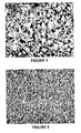
Figure 1 is an optical micrograph showing coke formed from a sponge coke making resid feed (Mid West Rocky Mountain) that contained no additive. The figure shows flow domains ranging in size from 10 to 35 micrometers (typical of sponge coke), and a coarse mosaic ranging from 5 to 10 micrometers (typical of shot coke). -
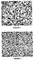
Figure 2 shows the effect of vanadium (as vanadyl naphthenate) on coke morphology. The figure is an optical micrograph showing coke formed from a resid feed containing 500 ppm (0.05 wt.%) vanadium in the form of vanadyl naphthenate. The figure shows a very fine mosaic compared toFigure 1 , in the range of 0.5 to 3 micrometers (typical of shot coke). -
Figure 3 shows the effect of sodium (as sodium naphthenate) on coke morphology. The figure is an optical micrograph showing coke formed from a resid feed containing 500 ppm (0.05 wt.%) sodium in the form of sodium naphthenate. The figure shows a fine mosaic compared toFigure 1 , in the range of 1.5 to 6 micrometers. -
Figure 4 is an optical micrograph showing coke formed from a transition coke making resid feed (Joliet Heavy Canadian) that contained no additive. The figure shows flow domains ranging in size from 10 to 35 micrometers (typical of sponge coke), and a coarse mosaic ranging from 5 to 10 micrometers (typical of shot coke). -
Figure 5 shows the effect of calcium on coke morphology of the transition coke making feed. The figure is an optical micrograph showing coke formed from a resid feed containing 250 wppm (0.025 wt.%) calcium in the form of calcium hydroxide. The figure shows a fine mosaic compared toFigure 4 , in the range of 1.5 to 6 micrometers. -
Figure 6 shows the effect fumed silica on coke morphology. The figure is an optical micrograph showing coke formed from a resid feed to which 2500 ppm of fumed silica was added. The figure shows some coke domains of 5-30 micrometers, but with abundant localized clusters of 1-5 micrometers. The implication is that the additive was not homogeneously dispersed in the vacuum resid and that if it was, or if a transition coke-forming vacuum resid was used, that free flowing shot coke would be formed. A transition coke-forming vacuum resid produces a mixture of coke morphologies, e.g., sponge coke and shot coke wherein the sponge coke can be bonded to the shot coke. -
Figure 7 shows the effect of elemental sulfur on coke morphology. The figure is an optical micrograph showing coke formed from a resid feed to which 20,000 ppm (2 wt.%) elemental sulfur was added. The figure shows some coke with a medium/coarse mosaic of 3 to 12 micrometers. Some coke in localized regions have a mosaic in the range of 1 to 3 micrometers. A mosaic in the range of <1 to 10 micrometers is typical of shot coke. -
Figure 8 also shows the effect of elemental sulfur on coke morphology. The figure is an optical micrograph showing coke formed from a resid feed to which 5,000 ppm (0.5 wt.%) elemental sulfur was added. The figure shows some coke with a medium/coarse mosaic of 3 to 12 micrometers. Some coke in localized regions have a mosaic in the range of 1 to 3 micrometers. A mosaic in the range of <1 to 10 micrometers is typical of shot coke. - All photomicrographs in these Figures used cross-polarized light, with a viewing area of 170 by 136 micrometers.
- Petroleum vacuum residua ("resid") feedstocks are suitable for delayed coking. Such petroleum residua are frequently obtained after removal of distillates from crude feedstocks under vacuum and are characterized as being comprised of components of large molecular size and weight, generally containing: (a) asphaltenes and other high molecular weight aromatic structures that would inhibit the rate of hydrotreating/hydrocracking and cause catalyst deactivation; (b) metal contaminants occurring naturally in the crude or resulting from prior treatment of the crude, which contaminants would tend to deactivate hydrotreating/hydrocracking catalysts and interfere with catalyst regeneration; and (c) a relatively high content of sulfur and nitrogen compounds that give rise to objectionable quantities of SO2, SO3, and NOx upon combustion of the petroleum residuum. Nitrogen compounds present in the resid also have a tendency to deactivate catalytic cracking catalysts.
- In an embodiment, resid feedstocks include but are not limited to residues from the atmospheric and vacuum distillation of petroleum crudes or the atmospheric or vacuum distillation of heavy oils, visbroken resids, tars from deasphalting units or combinations of these materials. Atmospheric and vacuum topped heavy bitumens can also be employed. Typically, such feedstocks are high-boiling hydrocarbonaceous materials having a nominal initial boiling point of 538°C or higher, an API gravity of 20°C or less, and a Conradson Carbon Residue content of 0 to 40 weight percent.
- The resid feed is subjected to delayed coking. Generally, in delayed coking, a residue fraction, such as a petroleum residuum feedstock is pumped to a heater at a pressure of 50 to 550 psig (344.7 to 3792.1 kPag). where it is heated to a temperature from 480°C to 520°C. It is then discharged into a coking zone, typically a vertically-oriented, insulated coker drum through an inlet at the base of the drum. Pressure in the drum is usually relatively low, such as 15 to 80 psig (103.4 to 551.6 kPag) to allow volatiles to be removed overhead. Typical operating temperatures of the drum will be between 410°C and 475°C. The hot feedstock thermally cracks over a period of time (the "coking time") in the coker drum, liberating volatiles composed primarily of hydrocarbon products, that continuously rise through the coke mass and are collected overhead. The volatile products are sent to a coker fractionator for distillation and recovery of coker gases, gasoline, light gas oil, and heavy gas oil. In an embodiment, a portion of the heavy coker gas oil present in the product stream introduced into the coker fractionator can be captured for recycle and combined with the fresh feed (coker feed component), thereby forming the coker heater or coker furnace charge. In addition to the volatile products, delayed coking also forms solid coke product.
- There are generally three different types of solid delayed coker products that have different values, appearances and properties, i.e., needle coke, sponge coke, and shot coke. Needle coke is the highest quality of the three varieties. Needle coke, upon further thermal treatment, has high electrical conductivity (and a low coefficient of thermal expansion) and is used in electric arc steel production. It is relatively low in sulfur and metals and is frequently produced from some of the higher quality coker feedstocks that include more aromatic feedstocks such as slurry and decant oils from catalytic crackers and thermal cracking tars. Typically, it is not formed by delayed coking of resid feeds.
- Sponge coke, a lower quality coke, is most often formed in refineries. Low quality refinery coker feedstocks having significant amounts of asphaltenes, heteroatoms and metals produce this lower quality coke. If the sulfur and metals content is low enough, sponge coke can be used for the manufacture of electrodes for the aluminum industry. If the sulfur and metals content is too high, then the coke can be used as fuel. The name "sponge coke" comes from its porous, sponge-like appearance. Conventional delayed coking processes, using the preferred vacuum resid feedstock of the present invention, will typically produce sponge coke, which is produced as an agglomerated mass that needs an extensive removal process including drilling and water-jet technology. As discussed, this considerably complicates the process by increasing the cycle time.
- Shot coke is considered the lowest quality coke. The term "shot coke" comes from its shape which is similar to that of BB sized (1/16 inch to 3/8 inch (1.6 to 9.5 mm)). balls. Shot coke, like the other types of coke, has a tendency to agglomerate, especially in admixture with sponge coke, into larger masses, sometimes larger than a foot in diameter. This can cause refinery equipment and processing problems. Shot coke is usually made from the lowest quality high resin-asphaltene feeds and makes a good high sulfur fuel source, particularly for use in cement kilns and steel manufacture. There is also another coke, which is referred to as "transition coke" and refers to a coke having a morphology between that of sponge coke and shot coke. For example, coke that has a mostly sponge-like physical appearance, but with evidence of small shot spheres beginning to form as discrete shapes.
- It has been discovered that substantially free-flowing shot coke can be produced by treating the residuum feedstock with one or more metal-containing additives of the present invention. The additives are those that enhance the production of shot coke during delayed coking. A resid feed is subjected to treatment with one or more additives, at effective temperatures, i.e., at temperatures that will encourage the additives' dispersal in the feed stock. Such temperatures will typically be from 70°C to 500°C, preferably from 150°C to 370°C, more preferably from 185°C to 350°C. The additive suitable for use herein can be liquid or solid form, with liquid form being preferred. The metals-containing additives that are used in the practice of the present invention are metal acetylacetonates, wherein the metal is selected from vanadium and/or nickel.
- It is to be understood that before or after the resid is treated with the additive, a caustic species, preferably in aqueous form, may optionally be added. The caustic can be added before, during, or after the resid is passed to the coker furnace and heated to coking temperatures. Spent caustic obtained from hydrocarbon processing can be used. Such spent caustic can contain dissolved hydrocarbons, and salts of organic acids, e.g., carboxylic acids, phenols, naphthenic acids and the like.
- The precise conditions at which the resid feedstock is treated with the additive is feed and additive dependent. That is, the conditions at which the feed is treated with the additive is dependent on the composition and properties of the feed to be coked and the additive used. These conditions can be determined conventionally. For example, several runs would be made with a particular feed containing an additive at different times and temperatures followed by coking in a Microcarbon Residue Test Unit (MCRTU). The resulting coke is then analyzed by use of a microscopy as set forth herein. The preferred coke morphology (i.e., one that will produce substantially free-flowing coke) is a coke microstructure of discrete micro-domains having an average size of 0.5 to 10 µm, preferably from 1 to 5 µm, somewhat like the mosaic shown in
Figures 2 ,3 and5 hereof. Coke microstructure that represents coke that is not free-flowing shot coke is shown inFigure 1 hereof, showing a coke microstructure that is composed substantially of non-discrete, or substantially large flow domains up to 60 µm or greater in size, typically from 10 to 60 µm. - Conventional coke processing aids, including an antifoaming agent, can be employed in the process of the present invention wherein a resid feedstock is air blown to a target softening point as described in
U.S. Patent No. 3,960,704 . While shot coke has been produced by conventional methods, it is typically agglomerated to such a degree that water-jet technology is still needed for its removal. - In one embodiment of the present invention, the resid feedstock is first treated with an additive that encourages the formation of substantially free-flowing coke. By keeping the coker drum at relatively low pressures, much of the evolving volatiles can be collected overhead, which prevents undesirable agglomeration of the resulting shot coke. The combined feed ratio ("CFR") is the volumetric ratio of furnace charge (fresh feed plus recycle oil) to fresh feed to the continuous delayed coker operation. Delayed coking operations typically employ recycles of 5 vol.% to 25% (CFRs of 1.05 to 1.25). In some instances there is 0 recycle and sometimes in special applications recycle up to 200%. CFRs should be low to aid in free flowing shot coke formation, and preferably no recycle should be used.
- While not wishing to be bound to any specific theory or model, the additive or mixture of additives employed are believed to function via one or more of the following pathways: a) as dehydrogenation and cross-linking agents, as agents that convert metals present in the feed into metal sulfides that are catalysts for dehydrogenation and shot coke formation; b) agents that add metal-containing species into the feed that influence or direct the formation of shot coke or are converted to species, e.g., metal sulfides, that are catalysts for shot coke formation; c) as particles that influence the formation of shot coke by acting as microscopic seed particles for the shot coke to be formed around, as Lewis acid cracking and cross-linking catalysts, and the like. Additives may also alter or build viscosity of the plastic mass of reacting components so that shear forces in the coker furnace, transfer line and coke drum roll the plastic mass into small spheres. Even though different additives and mixtures of additives may be employed, similar methods can be used for contacting the additive(s) with the feed.
- Typically, additive(s) are conducted to the coking process in a continuous mode. If needed, the additive could be dissolved or slurried into an appropriate transfer fluid, which will typically be solvent that is compatible with the resid and in which the additive is substantially soluble. The fluid mixture or slurry is then pumped into the coking process at a rate to achieve the desired concentration of additives in the feed. The introduction point of the additive can be, for example, at the discharge of the furnace feed charge pumps, or near the exit of the coker transfer line. There can be a pair of mixing vessels operated in a fashion such that there is continuous introduction of the additives into the coking process.
- The rate of additive introduction can be adjusted according to the nature of the resid feed to the coker. Feeds that are on the threshold of producing shot coke may require less additive than those which are farther away from the threshold.
- For additives that are difficult to dissolve or disperse in resid feeds, the additive(s) are transferred into the mixing/slurry vessel and mixed with a slurry medium that is compatible with the feed. Non-limiting examples of suitable slurry mediums include coker heavy gas oil, water, etc. Energy may be provided into the vessel, e.g., through a mixer for dispersing the additive.
- For additives which can be more readily dissolved or dispersed in resid feeds, the additive(s) are transferred into the mixing vessel and mixed with a fluid transfer medium that is compatible with the feed. Non-limiting examples of suitable fluid transfer mediums include warm resid (temp. between 150°C to 300°C), coker heavy gas oil, light cycle oil, heavy reformate, and mixtures thereof. Cat slurry oil (CSO) may also be used also, though under some conditions it may inhibit the additives' ability to produce loose shot coke. Energy may provided into the vessel, e.g., through a mixer, for dispersing the additive into the fluid transfer medium.
- The present invention will be better understood by reference to the following non-limiting examples that are presented for illustrative purposes.
- The resid feed is heated to 70-150°C to decrease its viscosity. The additive (in weight parts per million, wppm) is then added slowly, with mixing, for a time sufficient to disperse and/or solubilize the additive(s) (a "dispersing time"). For laboratory experiments, it is generally preferred to first dissolve and/or disperse the additive in a solvent, e.g., toluene, tetrahydrofuran, or water, and blend it with stirring into the heated resid, or into the resid to which some solvent has been added to reduce its viscosity. The solvent can then be removed. In a refinery, the additive contacts the resid when it is added to or combined with the resid feed. As discussed, the contacting of the additive and the feed can be accomplished by blending a feed fraction containing additive species (including feed fractions that naturally contain such species) into the feed. Additives in the form of organometallic compound(s) are generally soluble in the vacuum resids. To assure maximum dispersion of the additive into the vacuum resid feed, the reaction mixture can be heat soaked. In one example, the appropriate amount of metal acetylacetonate (acac) was dissolved in tetrahydrofuran (THF) under an inert atmosphere, then added to a round bottom flask containing the residuum in which it was to be dispersed. The THF / oil mixture was allowed to stir for 1 hr. at 50°C to distribute the metal substantially uniformly throughout the resid. The THF was then removed by roto-evaporation to leave the metal acetylacetonate well dispersed in the residuum. A sample of the mixture was analyzed for metals to verify the concentration of metal in the oil.
- The following tests were conducted using various additives to a resid feed. The tests with V acetylacetonate and/or nickel acetylacetonate are according to the invention; the tests with other additives are not according to the invention. Additive concentration, heat soak time, and the resulting coke morphology as determined from optical micrographs are set forth in Tables 1-7 below. Control samples of resid with no additive was used by way of comparison.
TABLE 1 EFFECT OF METAL ADDITIVE AGENTS ON MORPHOLOGY OF MCR COKE ON A SPONGE COKE-FORMING VACUUM RESID Additive Concentration (wppm) Heat Soak at 370°C (min) MCR Domain/ Mosaic-Domain Size/Comments (µm) None 0 30 5-30 - Sponge coke Vanadyl Naphthenate 1,000 None 0.5-3 µm very fine to fine mosaic. Shot coke Vanadium Naphthenate 2,500 30 0.5-1 µm very fine mosaic - shot coke Vanadium Sulfide 2,500 30 5-30 with localized 1-3 µm where VxSy exists Nickel Naphthenate 1,000 None 1-5 µm fine mosaic - Shot coke Nickel Naphthenate 2,500 None 0.5-3 µm very fine to fine mosaic. Shot coke Sodium Naphthenate 2,500 None 0.5-4 µm very fine to fine mosaic. Shot coke Iron Chloride 2,500 30 5-25 with localized 1-3 µm where sulfide exists-Illustrates effect of heterogeneity Iron Acetyl-acetonate 10,000 30 0.5 - 3 µm very fine mosaic. Shot coke Vanadyl Acetyl-acetonate 10,000 30 <0.5 µm ultra fine mosaic. Shot coke Vanadyl Acetyl-acetonate 1,000 30 0.5-2 µm very fine mosaic. Shot coke Nickel Acetyl-acetonate 10,000 30 0.5 - 2 µm very fine mosaic. Shot coke Nickel Acetyl-acetonate 1,000 30 1-4 µm fine/medium mosaic. Shot coke Mixture of Nickel and Vanadyl Acetyl-acetonates 5,000 ppm Ni 5,000 ppm V 30 <0.5 - 0.7 µm ultra fine mosaic. Shot coke Mixture of Iron and Vanadyl acetyl-acetonates 5,000 ppm Fe 5,000 ppm V 30 <0.5-1 µm very fine mosaic. Shot Coke Mixture of Iron and Nickel acetyl-acetonates 5,000 ppm Fe, 5,000 ppm Ni 30 0.5 - 3 µm fine mosaic. Shot coke. TABLE 2 EFFECT OF METAL ADDITIVE AGENTS ON MORPHOLOGY OF MCR COKE ON A SPONGE COKE-FORMING VACUUM RESID Sample No. Additive Additive (wppm) MCR (wt%) Microscopy on MCR Coke: Domain/Mosaic Size (µm) Coke Type Oil Soluble Additives 100-1 None -- 14.43, 15.45, 14.40, 14.50 Flow domains (10-35 µm) & coarse mosaic (5-10 µm) Sponge 113-11 Vanadyl Naphthenate1 2500 13.46 Extra fine mosaic (0.5-1.5 µm) Shot 113-1 Vanadyl Naphthenate 1000 14.22 Very fine mosaic (0.5-2µm) Shot 121-3 Vanadyl Naphthenate 500 15.31 Very fine mosaic (0.5-3µm) Shot 126-4 Vanadyl Naphthenate 300 15.38 Fine/Medium mosaic (1-5 µm) Shot 113-14 Sodium Naphthenate 2500 12.50 Very fine mosaic (0.5-3µm) Shot 113-4 Sodium Naphthenate 1000 12.20 Fine/medium mosaic (1-4µm) Shot 121-4 Sodium Naphthenate 500 13.17 Fine/Medium mosaic (1.5-6 µm) Shot 125-5 Sodium Naphthenate 300 14.29 Medium/Coarse mosaic (2-10 µm) Shot 113-13 Nickel Naphthenate 2500 14.36 Very fine mosaic (0.5-3µm) Shot 113-3 Nickel Naphthenate 1000 13.71 Fine/medium mosaic (1-4µm) Shot 127-3 Sodium Cresylate 1000 13.37 Fine/medium mosaic (1-4µm) Shot 127-2 Sodium Cresylate 500 12.68 Coarse mosaic/domains (3-15 µm) with localized regions 0.5-4µm. Transiti on 131-5 Sodium Cresylate on Heavy Canadian Transition Coke-former3 4302 19.90 Fine mosaic (0.5-3 µm) Shot 118-6 Vanadyl Acetyl-acetonate 2 3000 18.05 -- Shot 142-2 Vanadyl Acetyl-acetonate 2 1000 16.90 Very fine mosaic (0.5-2.5µm) Shot 142-1 Nickel Acetyl-acetonate 2 1000 16.51 Very fine/fine mosaic (0.5-4 µm) Shot 118-13 Vanadyl tetraphenylporphine 1000 17.05 Extra fine mosaic (<0.5-1µm) Shot 118-10 Nickel tetraphenylporphine 1000 17.93 Very fine mosaic (0.5-3µm) Shot (1) The naphthenate additives, dissolved in 3-5 mL of toluene were added slowly to the stirring vacuum resid at 100-125°C. Stirring was continued for 30 min and the toluene solvent was evaporated under a nitrogen flow to the tare weight of the resid plus additive. (2) Acac's were THF solubilized and added into the vacuum resid at 40°C. THF was removed under vacuum at 40-60°C. (3) Supplemented by 250 ppm V and 106 ppm Ni naturally occurring in this resid TABLE 3 EFFECT OF METAL ADDITIVE AGENTS ON MORPHOLOGY OF MCR COKE ON A SPONGE COKE-FORMING VACUUM RESID Sample No. Additive Additive (wppm) MCR (wt%) Microscopy on MCR Coke: Domain/Mosaic Size (µm) Coke Type Blender as Aqueous solution 136-1 Sodium Chloride 1000 14.1 Flow Domains (10-20 µm) with isolated areas of fine/medium mosaic (1-5 µm) Sponge 136-2 Sodium Sulfate 1000 15.7 Flow Domains (10-20 µm) with isolated areas of fine/medium mosaic (1-4 µm) Transition 136-3 Sodium Sulfide 1000 15.2 Fine/Medium mosaic (0.5-3 µm) Shot 136-4 Sodium Acetate 1000 13.4 Fine/Medium mosaic (1-5 µm) Shot 136-5 Ferric Chloride 1000 13.0 Flow Domains (10-20 µm) with isolated areas of fine/medium mosaic (1-5 µm) Transition 136-6 Zinc Chloride 1000 14.1 Flow Domains (10-20 µm) with isolated areas of fine/medium mosaic (1-5 µm) Sponge/ some Transition 136-7 Sodium Hydroxide 1000 14.4 Fine/Medium mosaic (0.5-4 µm) Shot 136-9 Potassium Hydroxide 1000 13.6 Very Fine mosaic (0.5-2.5 µm) Shot 136-10 Lithium Hydroxide 1000 12.6 Fine/Medium mosaic (0.5-5 µm) with extensive regions of coarse mosaic (5-10 µm) Transition The required amount of Additive agent dissolved in 20 mL of water at 80°C was slowly added to the vacuum resid in a blender at 100-125°C. The mixture was blended until homogeneous. Water was evaporated under a nitrogen flow while raising the temperature of the mixture to 150°C. TABLE 4 EFFECT OF METAL ADDITIVE AGENTS ON MORPHOLOGY OF MCR COKE ON A SPONGE COKE-FORMING VACUUM RESID Sample No. Additive Additive (wppm) MCR (wt%) Microscopy on MCR Coke: Domain/Mosaic Size (µm) Coke Type Blender as Slurry1 137-1 Vanadium Pentoxide 1000 14.2 Flow Domains (10-20 µm) and medium/coarse mosaic (3-10 µm) Sponge 137-2 FLEXICOKER Fines 1000 - V 20.3 Coarse mosaic (5-10 µm) with areas of fine/medium mosaic (1-5 µm) Transition 137-5 Tin Powder 1000 13.8 Flow Domains (10-25 µm) with coarse mosaic (5-10 µm) Sponge 137-6 Zinc Powder 1000 16.1 Domains (10-25 µm) and coarse mosaic (5-10 µm). Isolated areas of fine/medium mosaic (1-5 µm). Sponge/ Transition 140-10 Cesium Hydroxide 1000 14.3 Medium/Coarse mosaic (2-10 µm); ~1/3 molar equiv of Na. Shot 142-14 Cesium hydroxide 3,400 15.3 Very fine mosaic (0.5-2 µm). 140-8 Ferric Oxalate hydrate 1000 15.0 Flow Domains (10-30 µm) and isolated areas of fine/medium mosaic (1-5 µm). Transition 140-5 Ferric Acetate 1000 13.5 Flow Domains (10-30 µm) and isolated areas of fine/medium mosaic (1-5 µm). Transition 140-6 Zinc Acetate 1000 13.9 Flow Domains (10-35 µm) and coarse mosaic (5-10 µm). Sponge 140-9 Zinc Oxalate 1000 15.5 Flow Domains (10-35 µm) and coarse mosaic (5-10 µm). Sponge 140-7 Iron Naphthenate 1000 14.1 Fine/Medium mosaic (1-5 µm) and some coarse mosaic (5-10 µm) Shot (1)Blended as a slurry at 150°C without solvent TABLE 5 EFFECT OF METAL ADDITIVE AGENTS ON MORPHOLOGY OF MCR COKE ON A SPONGE COKE-FORMING VACUUM RESID Sample No. Additive Additive (wppm M) MCR (wt%) Microscopy on MCR Coke: Domain/Mosaic Size (µm) Coke Type 142-3 Fe Acetyl-acetonate 1000 14.8 Very fine mosaic (1-5 µm), some coarse mosaic (5-10 µm) Transition 114-2 Fe Acetyl-acetonate 1000 15.4 Very fine mosaic (0.5-3 µm) Shot 122-2 Ni Acetyl-acetonate + Fe Acetyl-acetonate 500 + 500 15.6 Very fine mosaic (0.5-3 µm) Shot 122-1 V Acetyl-acetonate + Fe Acetyl-acetonate 500 + 500 15.1 Very fine mosaic (<0.5-1 µm) Shot 121-1 Calcium Naphthenate 1000 14.6 Flow domains (10-25 µm) and coarse mosaic (5-10 µm) Sponge 121-2 Calcium Naphthenate 2500 14.1 Flow domains (10-15 µm) and coarse mosaic (5-10 µm) Sponge/ Transition 150-2 Calcium Acetyl-acetonate 5000 14.6 Small domains (10-15 µm) and medium/coarse mosaic (2-10 µm) Transition 125-12 Calcium acetate 5000 15.6 Coarse mosaic/small domains (5-15 µm) with abundant localized fine domains (0.5-3 µm) Transition 125-13 Calcium acetate 1000 14.6 Coarse mosaic/small domains (5-15 µm) with minor localized fine/medium mosaic (1-4 µm) Sponge 144-8 Sodium sulfonate 500 14.4 Flow domains (10-25 µm) and isolated areas of fine/medium mosaic (1-5 µm) Transition 144-9 Calcium sulfonate 500 16.3 Coarse mosaic domains (5-15 µm) and abundant areas of fine/medium mosaic (1-5 µm) Transition 146-1 Sodium hydrosulfide 1000 23.4 Medium/coarse mosaic (2-10 µm) Shot 146-2 Sodium borate 1000 14.9 Flow domains (10-30 µm) and areas of coarse mosaic (5-10 µm) Sponge 146-3 Potassium borate 1000 13.0 Flow domains (10-30 µm) and areas of coarse mosaic (5-10 µm) Sponge 146-4 Ferric sulfate 1000 14.7 Flow domains (10-30 µm) and areas of coarse mosaic (5-10 µm) Sponge 146-5 Ferric acetate 1000 14.5 Small domains (10-20 µm) and areas of medium/coarse mosaic (2-10 µm) 146-12 Zinc Naphthenate 1000 13.24 Domains/coarse mosaic (10-15 µm) and isolated areas of fine/medium mosaic (1-5 µm) Sponge 144-11 Mn porphyrin 1000 15.2 Medium/coarse mosaic (2-10 µm) and areas of fine/medium mosaic (1-5 µm) Transition/Shot 144-10 Porphine - NO METALS 3000 14.6 Coarse mosaic domains (5-20 µm) and areas of fine/medium mosaic (1-5 µm) Transition Acac's were THF solubilized and added into the vacuum resid at 40°C. THF was removed under vacuum at 40-60°C. Calcium salts were dissolved in water and blended into the resid at 100-125°C. TABLE 6 EFFECT OF METAL ADDITIVE AGENTS ON MORPHOLOGY OF MCR COKE OF A TRANSITION COKE-FORMING VACUUM RESID Sample No. Additive Additive (wppm) MCR (wt%) Microscopy on MCR Coke: Domain/Mosaic Size (µm) Coke Type 144-13 Heavy Canadian -- 16.0 142-8 Sodium hydroxide 250 19.8 Fine/medium mosaic (0.5-4 µm) Shot 142-5 Sodium cresylate 250 19.4 Fine/medium mosaic (0.5-6 µm) Shot 142-13 Sodium sulfonate 250 16.7 Fine/medium mosaic (1-7 µm) Shot 142-9 Potassium hydroxide 250 20.5 Fine/medium mosaic (0.5-6 µm) Shot 142-6 Potassium cresylate 250 16.5 Fine/medium mosaic (1-7 µm) Shot 142-10 Calcium hydroxide 250 20.6 Fine/medium mosaic (1-7 µm) Shot 142-12 Calcium sulfonate 250 19.8 Medium/coarse mosaic (2-9 µm) Shot 144-1 Sodium hydroxide 500 21.4 Fine/medium mosaic (0.5-3 µm) Shot 144-2 Sodium cresylate 500 19.9 Fine/medium mosaic (0.5-5 µm) Shot 144-3 Sodium sulfonate 500 17.6 Fine/medium mosaic (0.5-6 µm) Shot 144-4 Potassium hydroxide 500 19.3 Fine/medium/coarse mosaic (1-10 µm) Shot 144-5 Potassium cresylate 500 20.8 Fine/medium mosaic (1-6 µm) Shot 144-6 Calcium hydroxide 500 20.8 Fine/medium mosaic (1-6 µm) Shot 144-7 Calcium sulfonate 500 19.3 Fine/medium mosaic (1-7 µm) Shot Dissolved in water, heated to 80°C and blended into resid at 100-125°C in a blender. TABLE 7 MISCELLANEOUS Sample No. Additive Additive (wppm) MCR (wt%) Microscopy on MCR Coke: Domain/Mosaic Size (µm) Coke Type 140-1 75% Maya: 25% CHAD 22.4 Fine/Medium mosaic (1-7 µm) Shot 142-2 CHAD + sodium acetate 1,000 13.6 Fine/Medium mosaic (1-6 µm) Shot Coke 142-3 CHAD + iron naphthenate 1,000 11.3 Fine/Medium mosaic (1-7 µm) Shot Coke 146-6 Heavy Canadian + sodium acetate 250 21.4 Fine/medium mosaic (0.5-5 µm) Shot 146-7 Heavy Canadian + potassium acetate 250 18.2 Medium/Coarse mosaic (1-8 µm) Shot 146-8 Off-Shore Marlim -- 18.2 Flow domains (10-60 µm) Sponge 146-9 Off-Shore Marlim + NaOH 500 17.5 Domain/coarse (5-20 µm) and isolated areas of fine/medium mosaic (1-5 µm) Transition 146-10 Off-Shore Marlim + NaOH 1000 17.9 Medium/coarse mosaic (1-8 µm) and isolated areas of fine/medium mosaic (0.5-3 µm) Shot *NHI = n-heptane insolubles (asphaltenes) - The Heavy Canadian feed used in the examples herein contained 250 wppm V, 106 wppm Ni, 28 wppm Na, and 25 wppm Fe.
- The Maya feed contained 746 wppm V, 121 wppm Ni, 18 wppm Na, and 11 wppm Fe.
- The Off-Shore Marlim feed contained 68 wppm V, 63 wppm Ni, 32 wppm Na, and 25 wppm Fe.
- The Chad feed contained 0.7 wppm V, 26 wppm Na, 31 wppm Ni, and 280 wppm Fe.
TABLE 8 EFFECT OF SUBSTANTIALLY METALS-FEE ADDITIVES ON A SPONGE COKE - FORMING VACUUM RESID Additive Concentration (wppm) Heat Soak at 370°C (min) MCR Domain/ Mosaic-Domain Size/Comments (µm) None 0 30 5-30 - Sponge coke Sulfur 10,000 100 3-12 with occasional regions of 1-3 µm. Illustrates ability to form shot coke and the effect of heterogeneous dispersion of additive. Sulfur 20,000 30 Medium/coarse mosaic (3-12 µm) and abundant localized clusters 1-3 µm. H3PO4 2,500 30 5-25 with some regions of 1-4 µm. P2O5 2,500 30 Small domains (10-15 µm) and medium/coarse domains (3-10 µm) Fumed Silica 2,500 30 Illustrates effect of heterogeneous dispersion of additive. - Polarizing light microscopy was used in these examples for comparing and contrasting structures of green coke (i.e., non-calcined coke) samples.
- At the macroscopic scale, i.e., at a scale that is readily evident to the naked eye, petroleum sponge and shot green cokes are quite different; sponge has a porous sponge-like appearance, and shot coke has a spherical cluster appearance. However, under magnification with an optical microscope, or polarized-light optical microscope, additional differences between different green coke samples may be seen, and these are dependent upon amount of magnification.
- For example, utilizing a polarized light microscope, at a low resolution where 10 micrometer features are discernable, sponge coke appears highly anisotropic, the center of a typical shot coke sphere appears much less anisotropic, and the surface of a shot coke sphere appears fairly anisotropic.
- At higher resolutions, e.g., where 0.5 micrometer features are discernable (this is near the limit of resolution of optical microscopy), a green sponge coke sample still appears highly anisotropic. The center of a shot coke sphere at this resolution is now revealed to have some anisotropy, but the anisotropy is much less than that seen in the sponge coke sample.
- It should be noted that the optical anisotropy discussed herein is not the same as "thermal anisotropy", a term known to those skilled in the art of coking. Thermal anisotropy refers to coke bulk thermal properties such as coefficient of thermal expansion, which is typically measured on cokes which have been calcined, and fabricated into electrodes.
- Microcarbon residue (MCR) tests were performed on the above feeds to generate cokes to be evaluated by optical microscopy. MCR techniques are described in J. B. Green, et al., Energy Fuels, 1992, 6, 836-844. The following is the procedure used for the MCR tests:
Heating Profile Time (min) N2 Flow (cc/min) Heat from room temp to 100°C 10 66 Heat from 100°C to 300°C then to 500°C 30 66/19.5 Hold at 500°C 15 19.5 Cool to room temp 40 19.5 -
Figure 1 is a cross-polarized light photomicrograph showing the microstructure of the resulting coke from an untreated resid feed. The viewing area for both is 170 microns by 136 microns. The untreated residuum resulted in a coke with a microstructure that was not discrete fine domains. The domains were relatively large (10-35 µm) flow domains. This indicates that sponge coke will be produced in the coker drum of a delayed coker. The microstructure ofFigure 2 , in which the vacuum residuum sample was treated with 2500 ppm of vanadium as soluble vanadyl naphthenate, shows a dramatic reduction in flow domain size to relatively fine (0.5-1 µm) discrete fine domains indicating that free-flowing shot coke will be produced in the coker drum of a delayed coker.
Claims (5)
- A delayed coking process comprising:(a) heating a petroleum resid in a first heating zone, to a temperature below coking temperatures but to a temperature wherein the resid is a pumpable liquid;(b) conducting said heated resid to a second heating zone wherein it is heated to coking temperatures;(c) conducting said heated resid from said second heating zone to a coking zone wherein vapor products are collected overhead and a coke product is formed;(d) introducing into said resid from 100 to 100,000 wppm based on the total weight of the metal in the additive and feed of at least one metals-containing additive that is effective for the formation of substantially free-flowing coke, wherein said metals-containing additive is introduced into said resid at a point upstream of the second heating zone, upstream of said coking zone, or both wherein the metals-containing additive is selected from metal acetylacetonates wherein the metal is selected from vanadium and/or nickel.
- The process of claim1, wherein the residuum feedstock is vacuum resid.
- The process of claim1 or 2, wherein at least a portion of the additive is soluble in the feedstock.
- The process of any of the preceding claims, further comprising adding caustic to the resid feed.
- The process of any of the preceding claims wherein the coke produced is substantially shot coke.
Priority Applications (1)
| Application Number | Priority Date | Filing Date | Title |
|---|---|---|---|
| EP11192633A EP2428549A1 (en) | 2003-05-16 | 2004-05-14 | Delayed coking process for producing free-flowing shot coke |
Applications Claiming Priority (2)
| Application Number | Priority Date | Filing Date | Title |
|---|---|---|---|
| US47132403P | 2003-05-16 | 2003-05-16 | |
| PCT/US2004/015319 WO2004104139A1 (en) | 2003-05-16 | 2004-05-14 | Delayed coking process for producing free-flowing shot coke |
Related Child Applications (1)
| Application Number | Title | Priority Date | Filing Date |
|---|---|---|---|
| EP11192633A Division-Into EP2428549A1 (en) | 2003-05-16 | 2004-05-14 | Delayed coking process for producing free-flowing shot coke |
Publications (2)
| Publication Number | Publication Date |
|---|---|
| EP1633831A1 EP1633831A1 (en) | 2006-03-15 |
| EP1633831B1 true EP1633831B1 (en) | 2015-05-06 |
Family
ID=33476829
Family Applications (2)
| Application Number | Title | Priority Date | Filing Date |
|---|---|---|---|
| EP20040752350 Expired - Lifetime EP1633831B1 (en) | 2003-05-16 | 2004-05-14 | Delayed coking process for producing free-flowing shot coke |
| EP11192633A Withdrawn EP2428549A1 (en) | 2003-05-16 | 2004-05-14 | Delayed coking process for producing free-flowing shot coke |
Family Applications After (1)
| Application Number | Title | Priority Date | Filing Date |
|---|---|---|---|
| EP11192633A Withdrawn EP2428549A1 (en) | 2003-05-16 | 2004-05-14 | Delayed coking process for producing free-flowing shot coke |
Country Status (8)
| Country | Link |
|---|---|
| US (2) | US7306713B2 (en) |
| EP (2) | EP1633831B1 (en) |
| JP (1) | JP2006528727A (en) |
| CN (2) | CN102925182B (en) |
| AU (1) | AU2004241454B2 (en) |
| CA (1) | CA2522268C (en) |
| ES (1) | ES2543404T3 (en) |
| WO (1) | WO2004104139A1 (en) |
Families Citing this family (48)
| Publication number | Priority date | Publication date | Assignee | Title |
|---|---|---|---|---|
| US8147676B2 (en) * | 2001-12-04 | 2012-04-03 | Exxonmobil Research And Engineering Company | Delayed coking process |
| CA2522268C (en) | 2003-05-16 | 2012-07-10 | Exxonmobil Research And Engineering Company | Delayed coking process for producing free-flowing shot coke |
| US7645375B2 (en) | 2003-05-16 | 2010-01-12 | Exxonmobil Research And Engineering Company | Delayed coking process for producing free-flowing coke using low molecular weight aromatic additives |
| US7658838B2 (en) | 2003-05-16 | 2010-02-09 | Exxonmobil Research And Engineering Company | Delayed coking process for producing free-flowing coke using polymeric additives |
| US7935246B2 (en) | 2004-03-09 | 2011-05-03 | Baker Hughes Incorporated | Method for improving liquid yield during thermal cracking of hydrocarbons |
| US7425259B2 (en) | 2004-03-09 | 2008-09-16 | Baker Hughes Incorporated | Method for improving liquid yield during thermal cracking of hydrocarbons |
| US7935247B2 (en) | 2004-03-09 | 2011-05-03 | Baker Hughes Incorporated | Method for improving liquid yield during thermal cracking of hydrocarbons |
| AU2005245869A1 (en) * | 2004-05-14 | 2005-12-01 | Exxonmobil Research And Engineering Company | Delayed coking process for producing free-flowing coke using low molecular weight aromatic additives |
| MXPA06012949A (en) | 2004-05-14 | 2007-02-12 | Exxonmobil Res & Eng Co | Blending of resid feedstocks to produce a coke that is easier to remove from a coker drum. |
| MXPA06012602A (en) | 2004-05-14 | 2007-01-31 | Exxonmobil Res & Eng Co | Viscoelastic upgrading of heavy oil by altering its elastic modulus. |
| AU2005245881A1 (en) * | 2004-05-14 | 2005-12-01 | Exxonmobil Research And Engineering Company | Production and removal of free-flowing coke from delayed coker drum |
| US7594989B2 (en) | 2004-05-14 | 2009-09-29 | Exxonmobile Research And Engineering Company | Enhanced thermal upgrading of heavy oil using aromatic polysulfonic acid salts |
| US20060196811A1 (en) * | 2005-03-02 | 2006-09-07 | Eppig Christopher P | Influence of acoustic energy on coke morphology and foaming in delayed coking |
| CA2611763C (en) * | 2005-06-23 | 2014-12-23 | Bp Oil International Limited | Process for evaluating quality of coke and bitumen of refinery feedstocks |
| US7914668B2 (en) * | 2005-11-14 | 2011-03-29 | Exxonmobil Research & Engineering Company | Continuous coking process |
| US20080099722A1 (en) * | 2006-10-30 | 2008-05-01 | Baker Hughes Incorporated | Method for Reducing Fouling in Furnaces |
| US8372264B2 (en) * | 2006-11-17 | 2013-02-12 | Roger G. Etter | System and method for introducing an additive into a coking process to improve quality and yields of coker products |
| CA2669636A1 (en) * | 2006-11-17 | 2008-05-29 | Roger G. Etter | Catalytic cracking of undesirable components in a coking process |
| CA2671164C (en) * | 2006-12-01 | 2014-02-18 | Exxonmobil Research And Engineering Company | Improved fluidized coking process |
| US20080271639A1 (en) * | 2007-05-04 | 2008-11-06 | Sierra Process Systems, Inc. | Addition of spent activated carbon to asphalt compositions and to coking units as feedstock or quencher |
| US7951758B2 (en) * | 2007-06-22 | 2011-05-31 | Baker Hughes Incorporated | Method of increasing hydrolytic stability of magnesium overbased products |
| US7871510B2 (en) | 2007-08-28 | 2011-01-18 | Exxonmobil Research & Engineering Co. | Production of an enhanced resid coker feed using ultrafiltration |
| US7828959B2 (en) * | 2007-11-19 | 2010-11-09 | Kazem Ganji | Delayed coking process and apparatus |
| US7794587B2 (en) * | 2008-01-22 | 2010-09-14 | Exxonmobil Research And Engineering Company | Method to alter coke morphology using metal salts of aromatic sulfonic acids and/or polysulfonic acids |
| US20100326880A1 (en) * | 2009-06-25 | 2010-12-30 | Bp Corporation North America Inc. | Hydrocarbon Conversion Process Additive and Related Processes |
| US9139781B2 (en) * | 2009-07-10 | 2015-09-22 | Exxonmobil Research And Engineering Company | Delayed coking process |
| US8496805B2 (en) * | 2009-07-10 | 2013-07-30 | Exxonmobil Research And Engineering Company | Delayed coking process |
| US8658025B2 (en) * | 2010-03-25 | 2014-02-25 | Exxonmobil Research And Engineering Company | Biomass conversion process |
| US8603325B2 (en) * | 2010-03-25 | 2013-12-10 | Exxonmobil Research And Engineering Company | Biomass oil conversion process |
| US8512549B1 (en) | 2010-10-22 | 2013-08-20 | Kazem Ganji | Petroleum coking process and apparatus |
| US9023193B2 (en) * | 2011-05-23 | 2015-05-05 | Saudi Arabian Oil Company | Process for delayed coking of whole crude oil |
| CN102899079B (en) * | 2011-07-27 | 2014-09-10 | 中国石油化工股份有限公司 | Delayed coking method |
| EP2737008B1 (en) * | 2011-07-29 | 2018-08-15 | Saudi Arabian Oil Company | Delayed coking process utilizing adsorbent materials and apparatus therefor |
| US9282260B2 (en) | 2012-04-05 | 2016-03-08 | Baker Hughes Incorporated | Visualizing polynuclear aromatic hydrocarbons within the near infrared spectrum |
| WO2014046866A1 (en) * | 2012-09-21 | 2014-03-27 | Lummus Technology Inc. | Coke drum additive injection |
| US20150129460A1 (en) * | 2013-11-14 | 2015-05-14 | Indian Oil Corporation Limited | Thermal cracking additive compositions for reduction of coke yield in delayed coking process |
| US9944862B2 (en) | 2013-11-18 | 2018-04-17 | Indian Oil Corporation Limited | Process and a system for enhancing liquid yield of heavy hydrocarbon feedstock |
| US10960382B2 (en) | 2013-11-18 | 2021-03-30 | Indian Oil Corporation Limited | Catalyst for enhancing liquid yield in thermal coking process |
| US10053630B2 (en) | 2014-05-14 | 2018-08-21 | Exxonmobil Research And Engineering Company | Control of coke morphology in delayed coking |
| DE102016201429A1 (en) | 2016-01-29 | 2017-08-03 | Sgl Carbon Se | Novel coke with additives |
| US10591456B2 (en) | 2016-03-30 | 2020-03-17 | Exxonmobil Research And Engineering Company | In situ monitoring of coke morphology in a delayed coker using AC impedance |
| US10995278B2 (en) | 2019-09-10 | 2021-05-04 | Saudi Arabian Oil Company | Disposal of disulfide oil compounds and derivatives in delayed coking process |
| CN112745960B (en) * | 2019-10-30 | 2022-10-11 | 中国石油化工股份有限公司 | Auxiliary agent for biomass pyrolysis treatment and preparation method and application thereof |
| CN112574770B (en) * | 2020-11-03 | 2021-10-26 | 大连理工大学 | Preparation method of high-quality coal-based needle coke |
| EP4284894A1 (en) | 2021-01-29 | 2023-12-06 | Dorf Ketal Chemicals (India) Private Limited | Additive composition for reducing coke and increasing distillate during pyrolysis of a feedstock, and method of use thereof |
| EP4460545A4 (en) * | 2022-01-03 | 2026-01-07 | Reliance Industries Ltd | METHOD FOR THE PRODUCTION OF NEEDLE COKE |
| KR20250039313A (en) | 2022-07-20 | 2025-03-20 | 도르프 케탈 케미칼즈 (인디아) 프라이비트 리미티드 | Coke reducing additive composition and method of using the same |
| CN117626340B (en) * | 2023-11-14 | 2025-03-14 | 齐齐哈尔大学 | Three-dimensional chrysanthemum-shaped CoMoO4@Ni3V/NF heterostructure catalyst and preparation method and application thereof |
Family Cites Families (63)
| Publication number | Priority date | Publication date | Assignee | Title |
|---|---|---|---|---|
| US3475323A (en) | 1967-05-01 | 1969-10-28 | Exxon Research Engineering Co | Process for the preparation of low sulfur fuel oil |
| US3558474A (en) | 1968-09-30 | 1971-01-26 | Universal Oil Prod Co | Slurry process for hydrorefining petroleum crude oil |
| US3852047A (en) * | 1969-06-09 | 1974-12-03 | Texaco Inc | Manufacture of petroleum coke |
| US3617514A (en) | 1969-12-08 | 1971-11-02 | Sun Oil Co | Use of styrene reactor bottoms in delayed coking |
| US3707459A (en) | 1970-04-17 | 1972-12-26 | Exxon Research Engineering Co | Cracking hydrocarbon residua |
| US3684697A (en) | 1970-12-17 | 1972-08-15 | Bernard William Gamson | Petroleum coke production |
| JPS547802B1 (en) * | 1971-04-23 | 1979-04-10 | ||
| US3769200A (en) | 1971-12-06 | 1973-10-30 | Union Oil Co | Method of producing high purity coke by delayed coking |
| US4096097A (en) * | 1976-12-27 | 1978-06-20 | Mobil Oil Corporation | Method of producing high quality sponge coke or not to make shot coke |
| US4140623A (en) * | 1977-09-26 | 1979-02-20 | Continental Oil Company | Inhibition of coke puffing |
| CA1141320A (en) | 1979-12-28 | 1983-02-15 | Harvey E. Alford | Coking technique and means for making methane |
| US4298455A (en) | 1979-12-31 | 1981-11-03 | Texaco Inc. | Viscosity reduction process |
| CA1125686A (en) | 1980-07-03 | 1982-06-15 | Research Council Of Alberta | Hydrodesulfurization of coke |
| US4518457A (en) * | 1980-08-18 | 1985-05-21 | Olin Corporation | Raney alloy coated cathode for chlor-alkali cells |
| US4612109A (en) | 1980-10-28 | 1986-09-16 | Nl Industries, Inc. | Method for controlling foaming in delayed coking processes |
| JPS5790093A (en) * | 1980-11-27 | 1982-06-04 | Cosmo Co Ltd | Treatment of petroleum heavy oil |
| US4440625A (en) * | 1981-09-24 | 1984-04-03 | Atlantic Richfield Co. | Method for minimizing fouling of heat exchanges |
| US4455219A (en) * | 1982-03-01 | 1984-06-19 | Conoco Inc. | Method of reducing coke yield |
| US4430197A (en) | 1982-04-05 | 1984-02-07 | Conoco Inc. | Hydrogen donor cracking with donor soaking of pitch |
| US4411770A (en) * | 1982-04-16 | 1983-10-25 | Mobil Oil Corporation | Hydrovisbreaking process |
| US4427532A (en) * | 1982-09-28 | 1984-01-24 | Mobil Oil Corporation | Coking of coal with petroleum residua |
| JPS59189190A (en) * | 1983-04-12 | 1984-10-26 | シエブロン・リサ−チ・コンパニ− | Delayed coking process |
| US4518487A (en) | 1983-08-01 | 1985-05-21 | Conoco Inc. | Process for improving product yields from delayed coking |
| US4616308A (en) * | 1983-11-15 | 1986-10-07 | Shell Oil Company | Dynamic process control |
| US4549934A (en) | 1984-04-25 | 1985-10-29 | Conoco, Inc. | Flash zone draw tray for coker fractionator |
| AU580617B2 (en) | 1984-09-10 | 1989-01-19 | Mobil Oil Corporation | Process for visbreaking resids in the presence of hydrogen- donor materials and organic sulfur compounds |
| US4592830A (en) * | 1985-03-22 | 1986-06-03 | Phillips Petroleum Company | Hydrovisbreaking process for hydrocarbon containing feed streams |
| US4659453A (en) | 1986-02-05 | 1987-04-21 | Phillips Petroleum Company | Hydrovisbreaking of oils |
| US4713168A (en) * | 1986-08-29 | 1987-12-15 | Conoco Inc. | Premium coking process |
| US4927561A (en) | 1986-12-18 | 1990-05-22 | Betz Laboratories, Inc. | Multifunctional antifoulant compositions |
| CA2051083A1 (en) * | 1990-10-01 | 1992-04-02 | William N. Olmstead | Coking process using coal fly ash as an accelerator |
| US5160602A (en) | 1991-09-27 | 1992-11-03 | Conoco Inc. | Process for producing isotropic coke |
| US5258115A (en) * | 1991-10-21 | 1993-11-02 | Mobil Oil Corporation | Delayed coking with refinery caustic |
| US5174891A (en) * | 1991-10-29 | 1992-12-29 | Conoco Inc. | Method for producing isotropic coke |
| US5248410A (en) | 1991-11-29 | 1993-09-28 | Texaco Inc. | Delayed coking of used lubricating oil |
| FR2689137B1 (en) | 1992-03-26 | 1994-05-27 | Inst Francais Du Petrole | PROCESS FOR HYDRO CONVERSION OF HEAVY FRACTIONS IN LIQUID PHASE IN THE PRESENCE OF A DISPERSE CATALYST AND POLYAROMATIC ADDITIVE. |
| JP3260436B2 (en) * | 1992-09-02 | 2002-02-25 | 株式会社ジャパンエナジー | Processing method of polymer material |
| AU1292395A (en) | 1993-11-18 | 1995-06-06 | Mobil Oil Corporation | Disposal of plastic waste material |
| US6264829B1 (en) | 1994-11-30 | 2001-07-24 | Fluor Corporation | Low headroom coke drum deheading device |
| US5820750A (en) * | 1995-02-17 | 1998-10-13 | Exxon Research And Engineering Company | Thermal decomposition of naphthenic acids |
| US6169054B1 (en) * | 1997-04-11 | 2001-01-02 | Intevep, S.A. | Oil soluble coking additive, and method for making and using same |
| US5645711A (en) | 1996-01-05 | 1997-07-08 | Conoco Inc. | Process for upgrading the flash zone gas oil stream from a delayed coker |
| US5853565A (en) * | 1996-04-01 | 1998-12-29 | Amoco Corporation | Controlling thermal coking |
| US6387840B1 (en) | 1998-05-01 | 2002-05-14 | Intevep, S.A. | Oil soluble coking additive |
| AU8906998A (en) | 1998-06-11 | 1999-12-30 | Conoco Inc. | Delayed coking with external recycle |
| US6168709B1 (en) | 1998-08-20 | 2001-01-02 | Roger G. Etter | Production and use of a premium fuel grade petroleum coke |
| US6048904A (en) | 1998-12-01 | 2000-04-11 | Exxon Research And Engineering Co. | Branched alkyl-aromatic sulfonic acid dispersants for solublizing asphaltenes in petroleum oils |
| US20020179493A1 (en) * | 1999-08-20 | 2002-12-05 | Environmental & Energy Enterprises, Llc | Production and use of a premium fuel grade petroleum coke |
| CN1119389C (en) * | 1999-09-29 | 2003-08-27 | 中国石油化工集团公司 | Coking delay process for lowering foam layer in coke tower |
| US6611735B1 (en) * | 1999-11-17 | 2003-08-26 | Ethyl Corporation | Method of predicting and optimizing production |
| US6800193B2 (en) | 2000-04-25 | 2004-10-05 | Exxonmobil Upstream Research Company | Mineral acid enhanced thermal treatment for viscosity reduction of oils (ECB-0002) |
| US6489368B2 (en) | 2001-03-09 | 2002-12-03 | Exxonmobil Research And Engineering Company | Aromatic sulfonic acid demulsifier for crude oils |
| US6544411B2 (en) * | 2001-03-09 | 2003-04-08 | Exxonmobile Research And Engineering Co. | Viscosity reduction of oils by sonic treatment |
| ATE458798T1 (en) * | 2001-03-12 | 2010-03-15 | Curtiss Wright Flow Control | IMPROVED SYSTEM FOR REMOVING THE BOTTOM OF A COKING CHAMBER |
| US20040035749A1 (en) * | 2001-10-24 | 2004-02-26 | Khan Motasimur Rashid | Flow properties of heavy crude petroleum |
| US7247220B2 (en) | 2001-11-09 | 2007-07-24 | Foster Wheeler Usa Corporation | Coke drum discharge system |
| US20030102250A1 (en) * | 2001-12-04 | 2003-06-05 | Michael Siskin | Delayed coking process for producing anisotropic free-flowing shot coke |
| US20030127314A1 (en) | 2002-01-10 | 2003-07-10 | Bell Robert V. | Safe and automatic method for removal of coke from a coke vessel |
| US20030191194A1 (en) | 2002-04-09 | 2003-10-09 | Ramesh Varadaraj | Oil/water viscoelastic compositions and method for preparing the same |
| US6688913B2 (en) | 2002-04-17 | 2004-02-10 | Chun-De Li | Connector assembly structure |
| CN1246514C (en) * | 2002-08-20 | 2006-03-22 | 东北大学 | Method for preparing lignocellulose for road |
| US6843889B2 (en) | 2002-09-05 | 2005-01-18 | Curtiss-Wright Flow Control Corporation | Coke drum bottom throttling valve and system |
| CA2522268C (en) | 2003-05-16 | 2012-07-10 | Exxonmobil Research And Engineering Company | Delayed coking process for producing free-flowing shot coke |
-
2004
- 2004-05-14 CA CA2522268A patent/CA2522268C/en not_active Expired - Fee Related
- 2004-05-14 EP EP20040752350 patent/EP1633831B1/en not_active Expired - Lifetime
- 2004-05-14 ES ES04752350.1T patent/ES2543404T3/en not_active Expired - Lifetime
- 2004-05-14 US US10/846,033 patent/US7306713B2/en not_active Expired - Lifetime
- 2004-05-14 US US10/846,034 patent/US7303664B2/en not_active Expired - Lifetime
- 2004-05-14 EP EP11192633A patent/EP2428549A1/en not_active Withdrawn
- 2004-05-14 AU AU2004241454A patent/AU2004241454B2/en not_active Ceased
- 2004-05-14 CN CN201210233303.9A patent/CN102925182B/en not_active Expired - Fee Related
- 2004-05-14 CN CNA2004800134636A patent/CN1791661A/en active Pending
- 2004-05-14 WO PCT/US2004/015319 patent/WO2004104139A1/en not_active Ceased
- 2004-05-14 JP JP2006533120A patent/JP2006528727A/en active Pending
Also Published As
| Publication number | Publication date |
|---|---|
| WO2004104139A1 (en) | 2004-12-02 |
| US20040256292A1 (en) | 2004-12-23 |
| EP1633831A1 (en) | 2006-03-15 |
| US7306713B2 (en) | 2007-12-11 |
| US7303664B2 (en) | 2007-12-04 |
| EP2428549A1 (en) | 2012-03-14 |
| CN102925182B (en) | 2014-04-23 |
| AU2004241454B2 (en) | 2009-04-23 |
| CN102925182A (en) | 2013-02-13 |
| US20040262198A1 (en) | 2004-12-30 |
| CA2522268A1 (en) | 2004-12-02 |
| CN1791661A (en) | 2006-06-21 |
| CA2522268C (en) | 2012-07-10 |
| JP2006528727A (en) | 2006-12-21 |
| AU2004241454A1 (en) | 2004-12-02 |
| ES2543404T3 (en) | 2015-08-19 |
Similar Documents
| Publication | Publication Date | Title |
|---|---|---|
| US7303664B2 (en) | Delayed coking process for producing free-flowing coke using a metals-containing additive | |
| US8147676B2 (en) | Delayed coking process | |
| JP2006500431A (en) | Delayed coking process for producing anisotropic free-flowing shot coke | |
| US9139781B2 (en) | Delayed coking process | |
| EP1751253B1 (en) | Delayed coking process for the production of substantially fre-flowing coke from a deeper cut of vacuum resid | |
| US8496805B2 (en) | Delayed coking process | |
| US7658838B2 (en) | Delayed coking process for producing free-flowing coke using polymeric additives | |
| US7645375B2 (en) | Delayed coking process for producing free-flowing coke using low molecular weight aromatic additives | |
| CA2566121C (en) | Delayed coking process for producing free-flowing coke using polymeric additives | |
| US20050279673A1 (en) | Delayed coking process for producing free-flowing coke using an overbased metal detergent additive | |
| CN1954048A (en) | Delayed coking process for producing free-flowing coke using low molecular weight aromatic additives |
Legal Events
| Date | Code | Title | Description |
|---|---|---|---|
| PUAI | Public reference made under article 153(3) epc to a published international application that has entered the european phase |
Free format text: ORIGINAL CODE: 0009012 |
|
| 17P | Request for examination filed |
Effective date: 20051201 |
|
| AK | Designated contracting states |
Kind code of ref document: A1 Designated state(s): AT BE BG CH CY CZ DE DK EE ES FI FR GB GR HU IE IT LI LU MC NL PL PT RO SE SI SK TR |
|
| DAX | Request for extension of the european patent (deleted) | ||
| RIN1 | Information on inventor provided before grant (corrected) |
Inventor name: BROWN, LEO, D. Inventor name: THE OTHER INVENTORS HAVE AGREED TO WAIVE THEIR ENT Inventor name: BERNATZ, FRITZ, A. Inventor name: GORBATY, MARTIN, L. Inventor name: SISKIN, MICHAEL Inventor name: KELEMEN, SIMON, R. Inventor name: EPPIG, CHRISTOPHER, P. |
|
| RIN1 | Information on inventor provided before grant (corrected) |
Inventor name: THE OTHER INVENTORS HAVE AGREED TO WAIVE THEIR ENT Inventor name: EPPIG, CHRISTOPHER, P. Inventor name: GORBATY, MARTIN, L. Inventor name: SISKIN, MICHAEL Inventor name: KELEMEN, SIMON, R. Inventor name: BERNATZ, FRITZ, A. Inventor name: BROWN, LEO, D. |
|
| 17Q | First examination report despatched |
Effective date: 20091203 |
|
| REG | Reference to a national code |
Ref country code: DE Ref legal event code: R079 Ref document number: 602004047137 Country of ref document: DE Free format text: PREVIOUS MAIN CLASS: C10G0009000000 Ipc: C10B0057060000 |
|
| GRAP | Despatch of communication of intention to grant a patent |
Free format text: ORIGINAL CODE: EPIDOSNIGR1 |
|
| RIC1 | Information provided on ipc code assigned before grant |
Ipc: C10B 57/06 20060101AFI20141125BHEP Ipc: C10B 55/00 20060101ALI20141125BHEP |
|
| INTG | Intention to grant announced |
Effective date: 20141217 |
|
| GRAS | Grant fee paid |
Free format text: ORIGINAL CODE: EPIDOSNIGR3 |
|
| GRAA | (expected) grant |
Free format text: ORIGINAL CODE: 0009210 |
|
| RIN1 | Information on inventor provided before grant (corrected) |
Inventor name: EPPIG, CHRISTOPHER, P. Inventor name: BROWN, LEO, D. Inventor name: KELEMEN, SIMON, R. Inventor name: SISKIN, MICHAEL Inventor name: GORBATY, MARTIN, L. Inventor name: BERNATZ, FRITZ, A. Inventor name: FERRUGHELLI, DAVID, T. |
|
| AK | Designated contracting states |
Kind code of ref document: B1 Designated state(s): AT BE BG CH CY CZ DE DK EE ES FI FR GB GR HU IE IT LI LU MC NL PL PT RO SE SI SK TR |
|
| REG | Reference to a national code |
Ref country code: GB Ref legal event code: FG4D |
|
| REG | Reference to a national code |
Ref country code: CH Ref legal event code: EP |
|
| REG | Reference to a national code |
Ref country code: IE Ref legal event code: FG4D |
|
| REG | Reference to a national code |
Ref country code: DE Ref legal event code: R096 Ref document number: 602004047137 Country of ref document: DE Effective date: 20150611 |
|
| REG | Reference to a national code |
Ref country code: AT Ref legal event code: REF Ref document number: 725712 Country of ref document: AT Kind code of ref document: T Effective date: 20150615 |
|
| REG | Reference to a national code |
Ref country code: NL Ref legal event code: T3 |
|
| REG | Reference to a national code |
Ref country code: ES Ref legal event code: FG2A Ref document number: 2543404 Country of ref document: ES Kind code of ref document: T3 Effective date: 20150819 |
|
| REG | Reference to a national code |
Ref country code: AT Ref legal event code: MK05 Ref document number: 725712 Country of ref document: AT Kind code of ref document: T Effective date: 20150506 |
|
| PG25 | Lapsed in a contracting state [announced via postgrant information from national office to epo] |
Ref country code: PT Free format text: LAPSE BECAUSE OF FAILURE TO SUBMIT A TRANSLATION OF THE DESCRIPTION OR TO PAY THE FEE WITHIN THE PRESCRIBED TIME-LIMIT Effective date: 20150907 Ref country code: FI Free format text: LAPSE BECAUSE OF FAILURE TO SUBMIT A TRANSLATION OF THE DESCRIPTION OR TO PAY THE FEE WITHIN THE PRESCRIBED TIME-LIMIT Effective date: 20150506 |
|
| PG25 | Lapsed in a contracting state [announced via postgrant information from national office to epo] |
Ref country code: AT Free format text: LAPSE BECAUSE OF FAILURE TO SUBMIT A TRANSLATION OF THE DESCRIPTION OR TO PAY THE FEE WITHIN THE PRESCRIBED TIME-LIMIT Effective date: 20150506 Ref country code: GR Free format text: LAPSE BECAUSE OF FAILURE TO SUBMIT A TRANSLATION OF THE DESCRIPTION OR TO PAY THE FEE WITHIN THE PRESCRIBED TIME-LIMIT Effective date: 20150807 Ref country code: BG Free format text: LAPSE BECAUSE OF FAILURE TO SUBMIT A TRANSLATION OF THE DESCRIPTION OR TO PAY THE FEE WITHIN THE PRESCRIBED TIME-LIMIT Effective date: 20150806 |
|
| REG | Reference to a national code |
Ref country code: CH Ref legal event code: PL |
|
| PG25 | Lapsed in a contracting state [announced via postgrant information from national office to epo] |
Ref country code: DK Free format text: LAPSE BECAUSE OF FAILURE TO SUBMIT A TRANSLATION OF THE DESCRIPTION OR TO PAY THE FEE WITHIN THE PRESCRIBED TIME-LIMIT Effective date: 20150506 Ref country code: LI Free format text: LAPSE BECAUSE OF NON-PAYMENT OF DUE FEES Effective date: 20150531 Ref country code: EE Free format text: LAPSE BECAUSE OF FAILURE TO SUBMIT A TRANSLATION OF THE DESCRIPTION OR TO PAY THE FEE WITHIN THE PRESCRIBED TIME-LIMIT Effective date: 20150506 Ref country code: IT Free format text: LAPSE BECAUSE OF NON-PAYMENT OF DUE FEES Effective date: 20150514 Ref country code: CH Free format text: LAPSE BECAUSE OF NON-PAYMENT OF DUE FEES Effective date: 20150531 |
|
| REG | Reference to a national code |
Ref country code: DE Ref legal event code: R097 Ref document number: 602004047137 Country of ref document: DE |
|
| REG | Reference to a national code |
Ref country code: IE Ref legal event code: MM4A |
|
| PG25 | Lapsed in a contracting state [announced via postgrant information from national office to epo] |
Ref country code: CZ Free format text: LAPSE BECAUSE OF FAILURE TO SUBMIT A TRANSLATION OF THE DESCRIPTION OR TO PAY THE FEE WITHIN THE PRESCRIBED TIME-LIMIT Effective date: 20150506 Ref country code: SK Free format text: LAPSE BECAUSE OF FAILURE TO SUBMIT A TRANSLATION OF THE DESCRIPTION OR TO PAY THE FEE WITHIN THE PRESCRIBED TIME-LIMIT Effective date: 20150506 Ref country code: PL Free format text: LAPSE BECAUSE OF FAILURE TO SUBMIT A TRANSLATION OF THE DESCRIPTION OR TO PAY THE FEE WITHIN THE PRESCRIBED TIME-LIMIT Effective date: 20150506 Ref country code: MC Free format text: LAPSE BECAUSE OF FAILURE TO SUBMIT A TRANSLATION OF THE DESCRIPTION OR TO PAY THE FEE WITHIN THE PRESCRIBED TIME-LIMIT Effective date: 20150506 Ref country code: RO Free format text: LAPSE BECAUSE OF NON-PAYMENT OF DUE FEES Effective date: 20150506 |
|
| PLBE | No opposition filed within time limit |
Free format text: ORIGINAL CODE: 0009261 |
|
| STAA | Information on the status of an ep patent application or granted ep patent |
Free format text: STATUS: NO OPPOSITION FILED WITHIN TIME LIMIT |
|
| 26N | No opposition filed |
Effective date: 20160209 |
|
| REG | Reference to a national code |
Ref country code: FR Ref legal event code: PLFP Year of fee payment: 13 |
|
| PG25 | Lapsed in a contracting state [announced via postgrant information from national office to epo] |
Ref country code: IE Free format text: LAPSE BECAUSE OF NON-PAYMENT OF DUE FEES Effective date: 20150514 |
|
| PGRI | Patent reinstated in contracting state [announced from national office to epo] |
Ref country code: IT Effective date: 20160412 |
|
| PG25 | Lapsed in a contracting state [announced via postgrant information from national office to epo] |
Ref country code: SI Free format text: LAPSE BECAUSE OF FAILURE TO SUBMIT A TRANSLATION OF THE DESCRIPTION OR TO PAY THE FEE WITHIN THE PRESCRIBED TIME-LIMIT Effective date: 20150506 |
|
| REG | Reference to a national code |
Ref country code: FR Ref legal event code: PLFP Year of fee payment: 14 |
|
| PG25 | Lapsed in a contracting state [announced via postgrant information from national office to epo] |
Ref country code: HU Free format text: LAPSE BECAUSE OF FAILURE TO SUBMIT A TRANSLATION OF THE DESCRIPTION OR TO PAY THE FEE WITHIN THE PRESCRIBED TIME-LIMIT; INVALID AB INITIO Effective date: 20040514 |
|
| PG25 | Lapsed in a contracting state [announced via postgrant information from national office to epo] |
Ref country code: SE Free format text: LAPSE BECAUSE OF FAILURE TO SUBMIT A TRANSLATION OF THE DESCRIPTION OR TO PAY THE FEE WITHIN THE PRESCRIBED TIME-LIMIT Effective date: 20150506 Ref country code: CY Free format text: LAPSE BECAUSE OF FAILURE TO SUBMIT A TRANSLATION OF THE DESCRIPTION OR TO PAY THE FEE WITHIN THE PRESCRIBED TIME-LIMIT Effective date: 20150506 |
|
| PG25 | Lapsed in a contracting state [announced via postgrant information from national office to epo] |
Ref country code: TR Free format text: LAPSE BECAUSE OF FAILURE TO SUBMIT A TRANSLATION OF THE DESCRIPTION OR TO PAY THE FEE WITHIN THE PRESCRIBED TIME-LIMIT Effective date: 20150506 |
|
| PG25 | Lapsed in a contracting state [announced via postgrant information from national office to epo] |
Ref country code: LU Free format text: LAPSE BECAUSE OF NON-PAYMENT OF DUE FEES Effective date: 20150514 |
|
| REG | Reference to a national code |
Ref country code: FR Ref legal event code: PLFP Year of fee payment: 15 |
|
| PGFP | Annual fee paid to national office [announced via postgrant information from national office to epo] |
Ref country code: NL Payment date: 20190429 Year of fee payment: 16 |
|
| PGFP | Annual fee paid to national office [announced via postgrant information from national office to epo] |
Ref country code: IT Payment date: 20190527 Year of fee payment: 16 Ref country code: ES Payment date: 20190603 Year of fee payment: 16 Ref country code: DE Payment date: 20190412 Year of fee payment: 16 |
|
| PGFP | Annual fee paid to national office [announced via postgrant information from national office to epo] |
Ref country code: FR Payment date: 20190417 Year of fee payment: 16 Ref country code: BE Payment date: 20190418 Year of fee payment: 16 |
|
| PGFP | Annual fee paid to national office [announced via postgrant information from national office to epo] |
Ref country code: GB Payment date: 20190430 Year of fee payment: 16 |
|
| REG | Reference to a national code |
Ref country code: DE Ref legal event code: R119 Ref document number: 602004047137 Country of ref document: DE |
|
| REG | Reference to a national code |
Ref country code: NL Ref legal event code: MM Effective date: 20200601 |
|
| PG25 | Lapsed in a contracting state [announced via postgrant information from national office to epo] |
Ref country code: NL Free format text: LAPSE BECAUSE OF NON-PAYMENT OF DUE FEES Effective date: 20200601 |
|
| REG | Reference to a national code |
Ref country code: BE Ref legal event code: MM Effective date: 20200531 |
|
| GBPC | Gb: european patent ceased through non-payment of renewal fee |
Effective date: 20200514 |
|
| PG25 | Lapsed in a contracting state [announced via postgrant information from national office to epo] |
Ref country code: GB Free format text: LAPSE BECAUSE OF NON-PAYMENT OF DUE FEES Effective date: 20200514 Ref country code: FR Free format text: LAPSE BECAUSE OF NON-PAYMENT OF DUE FEES Effective date: 20200531 |
|
| PG25 | Lapsed in a contracting state [announced via postgrant information from national office to epo] |
Ref country code: DE Free format text: LAPSE BECAUSE OF NON-PAYMENT OF DUE FEES Effective date: 20201201 Ref country code: BE Free format text: LAPSE BECAUSE OF NON-PAYMENT OF DUE FEES Effective date: 20200531 |
|
| REG | Reference to a national code |
Ref country code: ES Ref legal event code: FD2A Effective date: 20210930 |
|
| PG25 | Lapsed in a contracting state [announced via postgrant information from national office to epo] |
Ref country code: ES Free format text: LAPSE BECAUSE OF NON-PAYMENT OF DUE FEES Effective date: 20200515 |
|
| PG25 | Lapsed in a contracting state [announced via postgrant information from national office to epo] |
Ref country code: IT Free format text: LAPSE BECAUSE OF NON-PAYMENT OF DUE FEES Effective date: 20200514 |