EP1633465B1 - Mixing bag for powder, apparatus, method and system for using same - Google Patents
Mixing bag for powder, apparatus, method and system for using same Download PDFInfo
- Publication number
- EP1633465B1 EP1633465B1 EP04754103A EP04754103A EP1633465B1 EP 1633465 B1 EP1633465 B1 EP 1633465B1 EP 04754103 A EP04754103 A EP 04754103A EP 04754103 A EP04754103 A EP 04754103A EP 1633465 B1 EP1633465 B1 EP 1633465B1
- Authority
- EP
- European Patent Office
- Prior art keywords
- solution
- mixing chamber
- bag
- process compatible
- interior
- Prior art date
- Legal status (The legal status is an assumption and is not a legal conclusion. Google has not performed a legal analysis and makes no representation as to the accuracy of the status listed.)
- Expired - Lifetime
Links
Images





Classifications
-
- A—HUMAN NECESSITIES
- A61—MEDICAL OR VETERINARY SCIENCE; HYGIENE
- A61J—CONTAINERS SPECIALLY ADAPTED FOR MEDICAL OR PHARMACEUTICAL PURPOSES; DEVICES OR METHODS SPECIALLY ADAPTED FOR BRINGING PHARMACEUTICAL PRODUCTS INTO PARTICULAR PHYSICAL OR ADMINISTERING FORMS; DEVICES FOR ADMINISTERING FOOD OR MEDICINES ORALLY; BABY COMFORTERS; DEVICES FOR RECEIVING SPITTLE
- A61J1/00—Containers specially adapted for medical or pharmaceutical purposes
- A61J1/14—Details; Accessories therefor
- A61J1/20—Arrangements for transferring or mixing fluids, e.g. from vial to syringe
-
- A—HUMAN NECESSITIES
- A61—MEDICAL OR VETERINARY SCIENCE; HYGIENE
- A61M—DEVICES FOR INTRODUCING MEDIA INTO, OR ONTO, THE BODY; DEVICES FOR TRANSDUCING BODY MEDIA OR FOR TAKING MEDIA FROM THE BODY; DEVICES FOR PRODUCING OR ENDING SLEEP OR STUPOR
- A61M1/00—Suction or pumping devices for medical purposes; Devices for carrying-off, for treatment of, or for carrying-over, body-liquids; Drainage systems
- A61M1/14—Dialysis systems; Artificial kidneys; Blood oxygenators ; Reciprocating systems for treatment of body fluids, e.g. single needle systems for hemofiltration or pheresis
- A61M1/16—Dialysis systems; Artificial kidneys; Blood oxygenators ; Reciprocating systems for treatment of body fluids, e.g. single needle systems for hemofiltration or pheresis with membranes
- A61M1/1654—Dialysates therefor
- A61M1/1656—Apparatus for preparing dialysates
-
- A—HUMAN NECESSITIES
- A61—MEDICAL OR VETERINARY SCIENCE; HYGIENE
- A61M—DEVICES FOR INTRODUCING MEDIA INTO, OR ONTO, THE BODY; DEVICES FOR TRANSDUCING BODY MEDIA OR FOR TAKING MEDIA FROM THE BODY; DEVICES FOR PRODUCING OR ENDING SLEEP OR STUPOR
- A61M1/00—Suction or pumping devices for medical purposes; Devices for carrying-off, for treatment of, or for carrying-over, body-liquids; Drainage systems
- A61M1/14—Dialysis systems; Artificial kidneys; Blood oxygenators ; Reciprocating systems for treatment of body fluids, e.g. single needle systems for hemofiltration or pheresis
- A61M1/16—Dialysis systems; Artificial kidneys; Blood oxygenators ; Reciprocating systems for treatment of body fluids, e.g. single needle systems for hemofiltration or pheresis with membranes
- A61M1/1654—Dialysates therefor
- A61M1/1656—Apparatus for preparing dialysates
- A61M1/1666—Apparatus for preparing dialysates by dissolving solids
-
- A—HUMAN NECESSITIES
- A61—MEDICAL OR VETERINARY SCIENCE; HYGIENE
- A61M—DEVICES FOR INTRODUCING MEDIA INTO, OR ONTO, THE BODY; DEVICES FOR TRANSDUCING BODY MEDIA OR FOR TAKING MEDIA FROM THE BODY; DEVICES FOR PRODUCING OR ENDING SLEEP OR STUPOR
- A61M1/00—Suction or pumping devices for medical purposes; Devices for carrying-off, for treatment of, or for carrying-over, body-liquids; Drainage systems
- A61M1/14—Dialysis systems; Artificial kidneys; Blood oxygenators ; Reciprocating systems for treatment of body fluids, e.g. single needle systems for hemofiltration or pheresis
- A61M1/16—Dialysis systems; Artificial kidneys; Blood oxygenators ; Reciprocating systems for treatment of body fluids, e.g. single needle systems for hemofiltration or pheresis with membranes
- A61M1/1654—Dialysates therefor
- A61M1/1656—Apparatus for preparing dialysates
- A61M1/1668—Details of containers
- A61M1/167—Flexible packaging for solid concentrates
-
- B—PERFORMING OPERATIONS; TRANSPORTING
- B01—PHYSICAL OR CHEMICAL PROCESSES OR APPARATUS IN GENERAL
- B01F—MIXING, e.g. DISSOLVING, EMULSIFYING OR DISPERSING
- B01F25/00—Flow mixers; Mixers for falling materials, e.g. solid particles
- B01F25/50—Circulation mixers, e.g. wherein at least part of the mixture is discharged from and reintroduced into a receptacle
- B01F25/53—Circulation mixers, e.g. wherein at least part of the mixture is discharged from and reintroduced into a receptacle in which the mixture is discharged from and reintroduced into a receptacle through a recirculation tube, into which an additional component is introduced
-
- B—PERFORMING OPERATIONS; TRANSPORTING
- B01—PHYSICAL OR CHEMICAL PROCESSES OR APPARATUS IN GENERAL
- B01F—MIXING, e.g. DISSOLVING, EMULSIFYING OR DISPERSING
- B01F33/00—Other mixers; Mixing plants; Combinations of mixers
- B01F33/45—Magnetic mixers; Mixers with magnetically driven stirrers
- B01F33/452—Magnetic mixers; Mixers with magnetically driven stirrers using independent floating stirring elements
-
- B—PERFORMING OPERATIONS; TRANSPORTING
- B01—PHYSICAL OR CHEMICAL PROCESSES OR APPARATUS IN GENERAL
- B01F—MIXING, e.g. DISSOLVING, EMULSIFYING OR DISPERSING
- B01F35/00—Accessories for mixers; Auxiliary operations or auxiliary devices; Parts or details of general application
- B01F35/50—Mixing receptacles
-
- B—PERFORMING OPERATIONS; TRANSPORTING
- B01—PHYSICAL OR CHEMICAL PROCESSES OR APPARATUS IN GENERAL
- B01F—MIXING, e.g. DISSOLVING, EMULSIFYING OR DISPERSING
- B01F35/00—Accessories for mixers; Auxiliary operations or auxiliary devices; Parts or details of general application
- B01F35/50—Mixing receptacles
- B01F35/513—Flexible receptacles, e.g. bags supported by rigid containers
Definitions
- the present invention relates to a method comprising the use of a defined mixing bag for packaging, storing and shipping (using a separate shipping container) a dry material to be mixed in the mixing bag; more particularly the method of the invention comprises the use of a defined preformed mixing bag adapted to store a dry powder which is to be mixed with a process compatible solution to form a suspension of powder in the solution having the material in suspension with a selected concentration which may be at least one of a high concentration capable of being diluted to a target concentration or at a target concentration intended for use without being diluted.
- mixing bags for storing a dry powder to be mixed in the mixing bag with a liquid is known in the art.
- the following prior art discloses typical mixing bags, apparatus and method for using such mixing bags.
- United States Patent 5,616,305 discloses a bag containing a selected quantity of dry powdered material wherein the volume of the bag is sufficient to add a liquid of a known maximum volume resulting in a solution in the form of a powdered salt concentrate wherein the solution is mixed by use of a pump connected to a water supply line.
- the powdered salt partially dissolves when the bag is completely filled with water.
- United States Patent 5,643,585 discloses a non-soluble articulate coloring material comprising dry ground red micro algae-derived material as a base color material.
- the non-soluble particulate matter was stored in a transparent plastic bag for testing as opposed to mixing with a fluid.
- United States Patents 6,149,294 ; 5,511,875 and 5,348,389 each disclose a system for mixing a powder and a fluid to produce a slurry.
- the system has a bag for mixing the powder and fluid therein and discloses use of a pump that recirculates and mixes the contents of the bag.
- United States Patent 5,362,642 discloses a cell culture media containment system having a mixing bag substantially enclosed within a storage bag powdered cell culture media and other constituents are introduced into the mixing bag and are mixed therein. Therefore, the reconstituted media is conveyed from the mixing bag into the storage bag.
- the mixing bag has an access port in the top to assist in the introduction of constituents into the mixing chamber and an introduction plate in the top having an opening allowing for insertion of tubes there through into the mixing chamber.
- the storage bag has an introduction plats having an opening for possessing tubing into the storage bag and to support a discharge tube.
- United States Patent 5,121,857 discloses a system for agitating and dispensing a mixture from a bag-in-box arrangement wherein the bag-in-box has a connector having an inlet port, an outlet port and a pump.
- United States Patent 5,709,467 discloses a bag or a pouch for mixing and dispensing an alginate and water composition and wherein the pouch or bag as a sealable opening.
- United States Patent 6,298,984 discloses a package containing a medium that must be combined with an activator and mixed before the medium can be used by an end user.
- United States Patent 4,948,013 discloses a method of mixing a powder and a fluid wherein a filter is used to allow only predetermined particles to be dispensed.
- United States Design Patent Number DES 413,258 discloses a flexible bag in the form of a dunnage bag having a valve, the dunnage bag apparently being used for personal storage of fluids or personal belongings.
- United States Design Patent Number DES 308,164 discloses a flexible container having an extended pouring spout for storing and dispensing fluids.
- United States Design Patent Number DES 304,546 discloses a flexible container having an opening which appears to be used for a filling the container with a fluid causing expansion of a bottom seam to accommodate a pre-determined volume fluid and wherein the opening is used to dispense the fluid.
- European Patent Office EPO Publication Number 0 152 283 discloses apparatus for dispensing a beverage from a reservoir wherein the reservoir containing the fluid is releasably connected to the apparatus wherein a pump continuously circulates the beverage around a fluid circuit.
- a pump continuously circulates the beverage around a fluid circuit.
- One or more dispensing valves or taps are located in the fluid circuit from which the beverage is to be dispensed.
- a metering pump is provided to effect mixing of the beverage within the reservoir when the beverage is to be formed of two or more liquids.
- European Patent Office EPO Publication Number 0 354 685 discloses a system for agitating and dispensing a fluid in a bag-in box arrangement and appears to be a foreign equivalent of United States Patent 5,121,857 discussed above.
- the bag has a V-shaped bottom with an access port in the bottom.
- Water is flowed through the access port and into the bag using water control means having a pump.
- the incoming water lifts and suspends the granules or powder.
- the filling of the bag is monitored by trip switches operatively attached to support the weight of the bag and contents. When the bag is filled sufficiently with water, the weight of the bag and contents trips the trip switches and a signal is sent to deactivate the pumps through control circuits.
- DE-A-10100549 discloses a salt concentrate container for dialysis apparatus, with 2 openings connected to a liquid circuit, wherein the salt concentrate is soluble in the dialysis liquid.
- EP-A-0619135 discloses a system for preparing a fluid for medical treatment by dissolving a first compound (such as a saline concentrate) in a second compound (such as an haemodialysis fluid), the system comprising the use of a specific ultrasound generator for assisting dissolution.
- the document EP-A-0619135 discloses a method comprising the use of a mixing bag having an interior mixing chamber having a first end located in a top section and a second end located in a bottom section and having a predetermined weight of a first compound (such as saline concentrate), said mixing bag having:
- the present invention is directed to a method comprising the use of a mixing bag, as defined in claim 1.
- the method of the invention enables mixing a dry powder with a process compatible solution in a preformed mixing bag to form a suspension of powder in the process compatible solution having the material in suspension with a selected concentration which is at least one of a high concentration capable of being diluted to a target concentration and a target concentration or, in the alternative, a selected density or a density within or acceptable range of densities.
- the mixing bag which may be a preformed mixing bag, comprises an interior mixing chamber having a volume sufficient to receive a predetermined weight of dry powder and a selected volume of process compatible solution to form a solution having powder in suspension with a selected concentration, e.g. g/L or selected density e.g. g/L 3 .
- the selected concentration is at least one of a high concentration capable of being diluted to a target concentration and a target concentration.
- the dry powder may be for example a Celpure ® media or e.g. a slightly hydrated media such as for example an LRA ® media.
- the selected concentration may be at a high concentration of Celpure ® media or LRA ® media, e.g. 100 g/L, to minimize the size of the system and the resulting solution may then be diluted with an inline mixer to achieve a lower target concentration, e.g. 2g/L.
- the mixing bag can be used in methods, apparatus and a system for forming a solution having the material in suspension with a selected concentration which is at least one of a high concentration capable of being diluted to a target concentration and a target concentration intended for use without being diluted.
- the selected concentration of the solution may be a high concentration to minimize system size and the resulting solution may then be diluted to achieve a lower target concentration.
- a mixing bag can be a preformed mixing bag having a selected shape.
- the mixing bag can be have a volume sufficient to receive a predetermined weight of dry material capable of being forming and remaining in suspension in a. process compatible solution and a selected volume of a process compatible solution to form a solution having the material in suspension with a selected concentration.
- the mixing bag can be have a volume sufficient to receive a predetermined weight of non-soluble powder capable of being forming and remaining in suspension in a process compatible solution and a selected volume of process compatible solution to form a solution having the material in suspension with a selected concentration.
- the non-soluble powder is diatomaceous earth.
- the non-soluble powder may comprise Celpure ® media, LRA ® media or sorbents.
- the mixing bag can have an outer member having a predetermined shape and a sidewall defining an interior mixing chamber having a volume sufficient to receive a predetermined weight of dry powder and a selected volume of process compatible solution to form a solution.
- the mixing bag can have an outer member which is in the shape of an elongated thin walled rectangular member having a hollowed-out passageway defining the interior mixing chamber.
- the mixing bag can have an outer member which is in the shape of an elongated thin walled cylindrical member having a hollowed-out passageway defining the interior mixing chamber.
- the mixing bag can have an outer member which is in the shape of an elongated thin walled cylindrical member having a hollowed-out passageway defining the interior mixing chamber wherein the interior mixing chamber includes an internal conical shaped hopper for receiving dry powder.
- the mixing bag comprises a third sealable opening which is configured for enabling transporting dry powder into the interior mixing chamber; a second sealable which is configured for at least one of enabling injection of process compatible solution into the interior mixing chamber to form a solution having the powder in suspension, enabling agitation of the powder and process compatible solution in the interior mixing chamber to form a solution having the powder in suspension with a selected concentration and enabling withdrawal of the solution with a selected concentration from the interior mixing chamber; and a first sealable opening which is configured for enabling at least one of agitation of the powder and process compatible solution in the interior mixing chamber to form a solution having the powder in suspension with a selected concentration, and enabling with drawal of the solution with a selected concentration from the interior mixing chamber.
- the method of the invention comprises the steps of injecting a selected volume of process compatible solution, e.g. water or feedstock solution, into a mixing bag through the second sealable opening; agitating through at least one of said first and second sealable openings the powder and process compatible solution in the interior mixing chamber to form a solution having powder in suspension with a selected concentration and withdrawing from the interior mixing chamber through at least on of said first and second sealable openings the solution with a selected concentration.
- the selected concentration is at least one of a high concentration capable of being diluted to a target concentration and a target concentration intended for use without being diluted.
- the mixing bag having an interior mixing chamber having a predetermined weight of dry powder e.g. a predetermined volume of diatomaceous earth
- a bioprocess container having three sealable inlets or openings.
- the three sealable openings can be used for a number of functions.
- the second sealable opening can be used for injecting a process compatible solution and/or a feedstock solution into the interior mixing chamber.
- a selected volume of process compatible solution e.g. make-up water or feedstock solution, can be injected into the container to form a solution comprising diatomaceous earth in suspension with a selected concentration, or selected solution density or a solution density which is within a density range of acceptable solution densities.
- the first and second sealable inlets or openings can be used to provide fluid flow for agitating or mixing the solution, for having a vent filter placed in line or for withdrawing solution with a selected concentration, or selected solution density or a solution density which is within a density range of acceptable solution densities.
- the selected solution density and density range of the solution and batch mixing specifications are determined by the requirements of the end user.
- the first and second sealable openings are provided to with draw the solution from the mixing bag.
- Dynamic depth filtration also known as pressure precoat filtration, is a constant flow, solid-liquid separation technique that has been practiced for over 75 years. Dynamic depth filtration uses a primary filter media that is a high purity, high-performance diatomite filter aid. Diatomite is a silica powder composed of diatoms, which are rigid, porous and irregular in shape, and Diatomite is essentially a dense, chert-like, consolidated diatomaceous earth.
- Diatomaceous earth is well known in the art and is made of opaline shells of diatoms and has a consistency of dry powder. Diatomaceous earth has a wide variety of uses including, without limitation, uses as a filter aid, paint additive, sorbent, abrasive and thermal insulator. Diatomaceous earth is also known as kieselguhr and tripolite.
- diatomaceous earth as used herein is intended to cover all of the above-described materials.
- diatomite products In the field of filtration, many methods of particle separation from fluids employ diatomite products as filter aids.
- the intricate and porous structure unique to diatomite silica is particularly effective for the physical entrapment of particles in filtration processes. It is common practice to employ diatomite products when improving he clarity of fluids that contain suspended particles or particulate matter, or have turbidity.
- Diatomire products are often applied to a septum to improve clarity and increase flow rate in filtration processes, in a step sometimes referred to as "precoating.” Diatomite is also often added directly to a fluid as it is being filtered to reduce the loading or plugging of undesirable particulate at the septum while maintaining a designed liquid flow rate, in a step often referred to as "body feeding.” Depending on the particular separation involved, diatomite products may be used in precoating, body feeding, or both. The principles involved with Diatomite filtration have been reviewed (Kiefer, 1991).
- diatomite products are blended together to further modify or optimize the filtration process.
- diatomite products are sometimes combined with other substances. In some cases, these combinations may involve simple mixtures, for example, with cellulose, activated charcoal or carbon, clay, or other materials. In other cases, these combinations are composites in which diatomite products are intimately compounded with other ingredients to make sheets, pads, or cartridges. Still more elaborate modifications of any of these diatomite products are used for filtration or separation, involving, for example, surface treatment and the addition of chemicals to diatomite products, mixtures, or their composites.
- diatomite products may also exhibit unique absorptive properties during filtration that can greatly enhance clarification or purification of a fluid.
- a hydroniumion i.e., H,0 +
- an acidic substance in solution for example, citric acid (i.e. C 6 H 8 O 7 )
- citric acid i.e. C 6 H 8 O 7
- diatomic products are usually processed to provide a range of filtration rates that are closely related to their permeability reported in units of Darcies.
- Diatomic filter aids are available in a wide range of permeabilities. The selection of a filter aid with a particular permeability suitable for a specific process depends on the flow rate and degree of fluid clarification desired for the particular application.
- Darcy's Law is well known to persons skilled in the art and is essentially an empirical law that governs flow through porous media and describes the relationship among flow rate, pressure drop and resistance. Functional filtration rates products are usually processed to provide a. range of filtration rates that are closely related to their permeability as reported in units of Darcies.
- One Darcy correspond to the permeability through a filter media 1 cm thick which allows 1 cm 3 of fluid with a viscosity of 1 centipoise to pass through an area of 1 cm 2 in 1 second under a pressure differential of 1 atmosphere.
- Dynamic depth filtering is used in the beverage and food manufacturing industries, e.g., as a filter for beer, and in the medical industry, e.g., as a filter aid for human serum filtration.
- CGMP Currant Good Manufacturing Practices of the FDA
- a Celpure ® media is used for solid-liquid separation in a pressure filtration system.
- Celpure ® media is available in a wide range of permeabilities.
- Table A sets forth data for certain of the commercially available Celpure ® media: Table A Grade Permeability (Darcy) Solids removed (micron) (1) Celpure 65 0.065 ⁇ 0.3 Celpure 100 0.100 0.3-0.45 Celpure 300 0.300 0.45-0.6 Celpure 1000 1.000 1-2 Note. (1) : Data is provided for comparison purposes only..
- Celpure ® filter aids are characterized by their powdered form dry density (0.10 g/cm 3 -0.40 g/cm 3 ) and light colors that range from white to pink to gray.
- the maximum wet density specifications for Celpure ® media grade is about 0.3 g/cm 3 .
- the suppliers of Diatomite comprising diatomaceous earth ship the material in bulk to an end user.
- the end user then mixes a predetermined volume of diatomaceous earth with a selected volume of process compatible solution, e.g. make-up water or feedstock solution, to form a solution comprising diatomaceous earth in suspension with a selected concentration, or selected solution density or when the solution density is within a density range of acceptable solution densities.
- process compatible solution e.g. make-up water or feedstock solution
- the selected solution density and density range of the solution and batch mixing specifications are determined by the requirements of the end user.
- the solution is then fabricated into or used as a diatomite filter media.
- the batch mixing is performed by an end user customer using a large batch mixing apparatus.
- a typical batch mixing process will use about one (1) ton by weight of diatomaceous earth.
- the diatomaceous earth is transported into or loaded into a large batch mixing apparatus mixing vessel.
- a selected volume of a process compatible solution e.g., make-up water, is then added to the diatomaceous earth.
- the ratio of process compatible solution to diatomaceous earth is dictated by the desired final selected concentration or density.
- the process compatible solution water from the local municipal water supply (which may or may not be filtered or preprocessed) is used as the process compatible solution.
- the large batch mixing apparatus then agitates the solution using mixing impellers or mixing blades for an appropriate mixing time, until the solution reaches the desired or selected concentration, density or a density in the density range.
- the selected concentration can be in the range of about 0.1 g/L to about 100 g/L.
- the solution is then used to mold or fabricate the desired filter media for use as a filter.
- the present invention has utility for improved handling of dry powder for forming solutions having dry powder in suspension with a selected concentration, generally, and specifically, for handling of diatomaceous earth for forming solutions having diatomaceous earth in suspension within a selected concentration wherein the selected concentration is at least one of a high concentration capable of being diluted to a target concentration and a target concentration intended for use without being diluted.
- the solution can then be fabricated into a filter media that is an inert, high purity, high-performance diatomite filter as described above.
- the method of the invention comprises the use of a mixing bag as shown in Fig. 1 .
- the mixing bag 30 has an outer member having a predetermined shape and a side wall defining an interior mixing chamber shown generally by arrow 32 having a volume sufficient to receive a predetermined weight of dry powder and a selected volume of process compatible solution to form a solution having powder in suspension with a selected concentration.
- the selected concentration is specified by the individual user.
- the end user may select the selected concentration to be a high concentration, e.g. a solution of Celpure ® media or LRA ® media at a concentration of 100 g/L to minimize the size of the processing system, and the resulting solution may then be diluted with an inline mixer to achieve a lower target concentration, e.g. 2 g/L.
- a high concentration e.g. a solution of Celpure ® media or LRA ® media at a concentration of 100 g/L to minimize the size of the processing system
- the resulting solution may then be diluted with an inline mixer to achieve a lower target concentration, e.g. 2 g/L.
- the solution density may be used in lieu of concentration and a selected solution density in a range of solution densities acceptable to or specified by the end user.
- solution densities for the selected concentration solutions in the range of about 2g/L to about 100 g/L are in a range of about 0.5 g/cm 3 to about 3 g/cm 3 , respectively.
- the interior mixing chamber 32 has a first end 36 and a second end 38 wherein the second end 38 is located in an opposed spaced relationship to the first end 36.
- the mixing bag 30 may be a preformed mixing bag having a selected shaped.
- the preformed mixing bag 30 has an outer member which is in the shape of an elongated thin walled rectangular member having a hollowed-out passageway defining the interior mixing chamber.
- the mixing bag 30 has a top section 42 and a bottom section 44. The first end 36 is located in the top section 42 and the second end 38 is located in the bottom section 44.
- the mixing bag 30 has' at least three sealable openings 50,52 and 54.
- the first sealable opening 50 extends from a location exterior to the mixing, bag 30 and into communication with the interior-mixing chamber 32 at the first end 36 of the top section 42.
- the first sealable opening 50 may be configured for at least one of enabling transporting dry powder into the interior mixing chamber 32, enabling agitation of the powder and process compatible solution to be transported into the interior mixing chamber 32 to form a solution having powder in suspension with a selected concentration, and enabling withdrawal of the solution at a selected concentration from the interior mixing chamber 32.
- the mixing bag 30 includes a third sealable opening 54 which is configured specifically for enabling transporting dry powder into the interior-mixing chamber 32.
- the first sealed opening 50 is used for at least one of enabling agitation of the material and process compatible solution in the interior mixing chamber 32 to form a solution having the material in suspension with a selected concentration and enabling withdrawal of the solution at a selected concentration from the interior mixing chamber 32.
- the second sealable opening 52 extends from a location exterior to the mixing bag 30 and into communication with the interior mixing chamber 32 at the second end 38 located in the bottom section 44. Opening 52 is configured.for at least one of injecting process compatible solution into the interior mixing chamber 32 to form a solution having powder in suspension, enabling agitation of the powder and process compatible solution in the interior mixing chamber 32 to form a solution having powder in suspension with a selected concentration and enabling withdrawal of the solution with a selected concentration from the interior mixing chamber 32.
- the third sealable opening 54 extends from a location exterior to the mixing bag 30 and into communication with the interior-mixing chamber 32 at the first end 36 in top section 42. Opening 54 is configured for enabling transporting dry powder into the interior-mixing chamber 32.
- the structure of the sealable opening 54 includes a sanitary port assembly which is discussed in greater detail in the discussions of Fig. 14A and Fig. 14B .
- Fig. 1 includes, as an optional opening, an auxiliary opening 60.
- Auxiliary opening 60 may be used during the process of fabricating a preformed mixing bag or could be configured to function as an air vent, degassing port for discharging biological gasses or as a vent check valve to enable expulsion or venting of gas of air from the mixing bag.
- sealable opening 50 is configured to be sealed upon completion of transporting dry powder into the interior mixing chamber and is to be unsealed for enabling agitation of a powder and process compatible solution to form a solution having powder in suspension with a selected concentration and enabling withdrawal of the solution at said selected concentration from the interior mixing chamber 32.
- sealable opening 52 is configured to be sealed sealed at least one of before commencement of transporting dry powder into the interior mixing chamber and after completion of transporting dry powder into the interior mixing chamber 32. Opening 52 is to be unsealed for at least one of enabling injection of a process compatible solution into the interior mixing chamber 32 to form a solution having powder in suspension, enabling agitation of a powder and process compatible solution to form a solution having powder in suspension with a selected concentration and withdrawal of solution from the interior mixing chamber with a selected concentration.
- a mixing bag 30 filled with a predetermined weight of dry powder 68 is shown as being placed in a shipping container 70 having a bottom member 72 and a recloseable top member 76
- the shipping container 70 may be fabricated to have a preformed shipping support member formed in the bottom member 72 or, in the alternative, may include a separate insertable shipping support member which is placed in the bottom of the shipping container 70 prior to inserting of the mixing bag (filled or unfilled) into the shipping container 70.
- the preformed shipping support member formed in the bottom member 72 or the separate insertable shipping support member are shown by dashed lines 78 and typically is conical shaped member with the base positioned to receive and support the mixing bag 30 containing the dry powder 68.
- the shipping container 70 is used for shipping the preformed mixing bag 30 filled with a predetermined weight of dry powder 68 to an end user for subsequent injection of'a process compatible solution into the interior mixing chamber 32 to form a solution, also known as a slurry, having powder in suspension.
- the preformed mixing bag 30 be placed into a shipping container 70 prior to the step of transporting dry powder 68 from a dry powder source through the first sealable opening 50, or in the alternative opening 54, into the interior mixing chamber 32 such that the mixing bag 30 has the dry powder 68 transported into the interior mixing chamber 32 when the mixing bag 30 is located within the shipping container 70.
- the preformed mixing bag 30 can be placed into a shipping container 70 subsequent to the step of transporting dry powder. 68 from a dry powder source through the first sealable opening 50, or in the alternative opening 54, into the interior mixing chamber 32 such that the mixing bag 30 has the dry powder 68 in the interior mixing chamber 32 when the mixing bag is placed within the shipping container 70.
- Figs. 3 through 6 show the structure of the preformed mixing bag 30 in greater detail.
- the preformed mixing bag 30 fabricated with three sealable openings, openings 50, 52 and 54.
- the sealable opening 54 is used for enabling transporting dry powder into the interior-mixing chamber 32.
- Sealable opening 52 is used for injecting a process compatible solution into the interior mixing chamber 32 to form a solution having powder in suspension, enabling agitation of the powder and process compatible solution in the inferior mixing chamber 32 to form a solution having powder in suspension with a selected concentration and enabling withdrawal of the solution with a selected concentration from the interior mixing chamber 32.
- the sealable opening 50 is used for enabling agitation of the powder and process compatible solution to be transported into the interior mixing chamber 32 to form a solution having powder in suspension with a selected concentration and enabling withdrawal of the solution at the selected concentration from the interior mixing chamber 32.
- the mixing bag 30 of Figs. 1 through 6 is show as a preformed mixing bag 30 having a first sealable opening 50 and the third sealable opening 54 in the first end 36 and a second sealable opening 52 in the second end 38.
- the third sealable opening 54 is used for filling the interior mixing chamber 32 with a predetermined weight of dry material.
- the first sealable opening 50 is used for agitation of the solution and for enabling withdrawal of the solution at a selected concentration from the interior mixing chamber 32.
- the second sealable opening 52 is used for infecting a process compatible solution into the interior mixing chamber 32 to form a solution having powder in suspension, enabling agitation of the powder and process compatible solution in the interior mixing chamber 32 to form a solution having powder in suspension with a selected concentration and enabling withdrawal of the solution with a selected concentration from the interior mixing chamber 32.
- the first end 36 supports the first sealable opening 50 and the third opening 54.
- Opening 54 may be in the form of a port having a collar which terminates in'an orifice which can be sealed and unsealed as depicted in Fig. 14A and Fig. 14B .
- the first sealable opening may be fabricated using sealing techniques which are known to persons skilled in the art.
- conventional sanitary fittings are used which utilize a design that, when tightened, allow the gasket to extrude into the boreline of process piping and create a barrier that holds fluids. Examples of such a known sealable openings or sanitary fittings are Tri-Clamp ® brand sanitary fittings manufactured by Tri-Clover which comprises stainless steel components.
- Plastic disposable versions of sanitary fittings are available under the trademark SterilEnz Fittings through Paw BioScience Products.
- the second end 38 supports the second scalable opening 52.
- Sealable opening 52 may be fabricated using sealing techniques which are known to persons skilled in the art as described above.
- the collar of the sealable opening 52 may become filled and possibly impacted by dry powder which could interfere with the step of injecting a process compatible solution through the salable opening arising from dry powder clogging the opening.
- This problem can be overcome by first tying off the collar from the exterior with a tying member 80 illustrated by dashed circle, e.g. rope, to collapse or restrict the collar of the sealable opening 52 to prevent the dry powder form becoming impacted in the collar.
- the tying member 80 is removed.
- Fig. 7 illustrates a method for filling a mixing bag with a dry powder.
- the method comprises the steps of forming a mixing bag as described above, having an interior mixing chamber having a volume sufficient to receive a predetermined weight of dry powder and a selected volume of process compatible solution to form a solution having powder in suspension with a selected concentration.
- the mixing bag 30 of Fig. 1 is show as a preformed mixing bag 30 having a first sealable opening 50, a second sealable opening 52 and a third sealable opening 54.
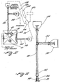
- a mixing control system 90 having a computer System 92 is used to control the method of using a preformed mixing bag 3 0 having the interior mixing chamber 32 filled with a predetermined weight of dry powder 68, shown in Fig. 2 , to form a solution having powder in suspension with a selected concentration.
- the apparatus includes the mixing control system 90, a first conduit system 100, a second conduit system 102, a pump 106, a filtering system or filter 108 and clamps 110 and 112.
- the pump 106 is operatively connected to a source of process compatible solution 120 through a control valve 122.
- a concentration sensor or solution density sensor 130 may be used to monitor the concentration or solution density, respectively, of the solution during agitation.
- Solution may be withdrawn from the interior mixing chamber 32 through withdrawal member 154 or, alternatively a shown by dashed arrow 148.
- the filtering of the solution having powder in suspension through a filter 108 removes unwanted particles therefrom.
- the computer system 92 can control the operation of: (i) the pump 106 through a control line shown by dashed line 138; (ii) the control valve 122 through a control line shown by dashed line 132; (iii) clamp 110 through :a control line shown by dashed line 134; and (iv) clamp 112 through a control line shown by dashed line 136.
- the filter 108 can be operated under computer control through a control line shown by dashed line 142.
- the sensor 130 which may monitor the concentration or solution density, can be operated under computer control through a control line shown by dashed line 7.46.
- computer and "computer system” is intended to include all ancillary components such as, without limitation network servers, storage devices including rotating disk memory storage systems, modems, communication lines, digital subscriber linens (“DSL”), keyboards and the like.
- network servers including rotating disk memory storage systems, modems, communication lines, digital subscriber linens (“DSL”), keyboards and the like.
- DSL digital subscriber linens
- FIG. 9 shows the step of injecting a selected volume of a process compatible solution from the source of process compatible solution 120 through the control valve 122 and pump 106 through the second conduit system 102 into a mixing bag 30 through opening 52.
- Control valve 110 is closed such that the pump 106 pressure is used to inject the process compatible solution through the second conduit system 102 and opening 52 in to the interior mixing chamber 32 having a. predetermined volume of dry powder.
- FIG. 10 illustrates the steps of enabling agitation of the powder and process compatible solution to form a solution having powder in suspension with a selected concentration, filtering of the solution and for enabling withdrawal of the solution from the interior mixing chamber with a selected concentration under control of a mixing control system 90 of Fig. 8 .
- the step of enabling agitation of the powder and process compatible solution in the interior mixing chamber 32 is commenced to form a solution having powder in suspension with a selected concentration.
- Clamp 110 is opened to permit passage of solution under pump pressure to pass through filter 108.
- Clamp 112 is closed to direct the solution through the inlet 150 of filter 108, through the filter 108 and out of the outlet 152.
- the solution flow is from the interior mixing chamber 32, out of opening 52, through the second conduit system 102, through the inlet 150, filter 108 and outlet 152, through the first conduit system 100, through opening 50-back into the interior mixing chamber 32.
- the step of withdrawal is illustrated in Fig. 10 .
- the solution is selectively withdrawn from the interior mixing chamber 32 through either the opening 52 via the withdrawal member 154 having an orifice operatively connected to the opening 52 or conduit section 148 located adjacent the first opening 50.
- Fig. 11 is a diagrammatic representation of the mixing bag 30 of the present invention having a filling conduit system 162 that is adapted for transporting dry powder into the interior mixing chamber through either first opening 50 or third opening 54 depending on the configuration of the preformed mixing bag 30.
- Fig. 11 is a diagrammatic illustration of how the first conduit system 100 and a second conduit system 102 are operatively removeably connected to openings 50 and 52, respectively.
- the dashed lines 158 and 160 represent'flexible connecting hoses which operatively connect the first conduit system 100 to filter 108 and pump 106, shown in Fig. 8 , and the second conduit system 102 to the pump 106.
- a controller 156 may be used for controlling the injecting make-up process compatible solution to inject a selected volume of process compatible solution into the interior mixing chamber.
- the controller may be the mixing control system 90 having a computer system 92 shown in Fig. 8 four controlling the method of using a preformed mixing bag 30 having the interior mixing chamber 32 filled with a predetermined weight of dry powder 68, shown in Fig. 2 , to form a solution having powder in suspension with a selected concentration.
- Fig. 12 is a top plan view of the first conduit system 100 of Fig. 11 illustrates that the first conduit system 100 is operatively removeably connected to opening 50 for enabling agitating the solution of powder and process compatible solution in the interior mixing chamber to form a solution of the process compatible solution having the powder in suspension with a selected concentration and enabling withdrawal of the solution with a selected concentration from the interior mixing chamber.
- the first conduit system 100 has a distal end 164 terminating in an insertion sleeve 166 that removeably couples to extension 168 of opening 50.
- the distal end 164 may be a flexible section to facilitate easy coupling of insertion sleeve 166 with extension 168.
- Fig. 13 is a top plan view of the second conduit system 102 of Fig. 11 operatively removeably connected to opening 52 for at least one of injecting process compatible solution .into the interior mixing chamber to form a solution having powder in suspension, enabling agitation of the powder and process compatible solution in the interior mixing chamber to form a solution having powder in suspension with a selected concentration and enabling withdrawal of the solution with a selected concentration from the interior mixing chamber.
- the second conduit system 102 has a distal end 170 terminating in an insertion sleeve 174 which removeably couples to extension 176 of opening 52.
- the distal end 170 may be a flexible section to facilitate easy coupling of insertion sleeve 174 with extension 176 of opening 52.
- Figs. 12 and 13 the exposed proximal ends of the first conduit system 100 and the second conduit system 102 are enclosed or sealed with a sealing enclosure 178 to prevent contamination.
- Fig. 14A is an exploded front elevational view of the third sealable opening 54 in the form of a sanitary port or sanitary fitting assembly and the assembly is shown generally as sealing assembly 182.
- the sealing assembly 182 is used for enabling transporting a predetermined weight of dry powder into the interior mixing chamber 32 of a mixing bag 30.
- the sealing assembly 182 includes a collar section 180 having a sealing rim 184 which is operatively connect to the opening 54.
- a sealing washer 186 is positioned between the sealing rim 184 and a sealing cover 188.
- a port securing member 192 has an adjustable threaded member 194 to permit the port securing member 192 is be positioned around the sealing rim 184 and enclose the sealing washer 186 and sealing cover 188.
- the adjustable threaded member 194 is then tightened to cause the port-securing member to form a seal of the opening 54.
- the sealing assembly 182 permits easy sealing and unsealing of opening 54.
- the same sealing assembly 182 could likewise be used for openings 50 and 52.
- Fig.. 14B is an exploded front elevational view of the third sealable opening 54 in the form of a sanitary port or sanitary fitting assembly having a filing extension and the assembly is shown generally as sealing assembly 196.
- the sealing assembly 196 is used for enabling transporting a predetermined weight of dry powder into the interior mixing chamber 32 of a mixing.bag 30.
- the sealing assembly 196 includes a collar section 180 having a sealing rim 184 which is operatively connect to the opening 54.
- a sealing washer 186 is positioned between the sealing rim 184 and a filing extension housing 198 having a mating washer surface 200 for sealably engaging the sealing washer 186
- a port securing member 192 has an adjustable threaded member 194 to permit the port securing member 192 to be positioned around the sealing rim 184 and mating washer surface 200 of a filing extension housing 198 enclosing the sealing washer 186.
- the adjustable threaded member 194 is then tightened to form a seal of the opening 54.
- the sealing assembly 182 permits easy sealing and unsealing of opening 54.
- Fig. 15 is a pictorial representation of yet another embodiment of a preformed mixing bag 300 for practicing the teachings of the present invention.
- the preformed mixing bag 300 has a first sealable opening 350, a second sealable opening 352 and a third sealable opening 360.
- the mixing bag 302 has a magnetically controlled impeller 406 located in the interior-mixing chamber 380 which is used for agitating the solution.
- the magnetically controlled impeller 406 is magnetically coupled to a magnetic driving member 402 which is driven by shaft 400.
- the magnetically controlled impeller 406 located in the interior mixing chamber 380, is illustrated as being magnetically coupled to the magnetic driving member 402 via magnetic lines of force 412 by rotation of shaft 400 driven by motor 410.
- Such an agitation apparatus may be used for selected volumes of dry powder in excess of 20 kg.
- agitation as used herein is used in its broadest sense and is intended to include all known apparatus and systems for mixing powder and fluids or liquids to form a solution including, without limitation, pumps, magnetic mixing apparatus, mechanical vibration apparatus, mechanical mixing apparatus wherein a mixing apparatus may be inserted through a opening to mix the solution, mechanical mixing apparatus having impellers driven by a shaft and motor or the like.
- Fig. 17 is a block diagram of the method performed usually performed at a first location, typically the location of the manufacturer or distributor, for filling a preformed mixing bag having an interior mixing chamber configured to have a volume sufficient to receive a predetermined weight of dry powder and a selected volume of process compatible solution to form a solution having powder in suspension with a selected concentration and shipping the same in a shipping container to an end user.
- a preformed mixing bag which has been formed and which is ready to fill is represented by block 500.
- the appropriate opening is unsealed as represented by block 502.
- the mixing bag is filled with a selected volume of dry powder as represented by block 504.
- the filled mixing bag with the dry powder is then shipped to an end user in a shipping container as represented by arrow 520.
- Fig. 18 is a block diagram of the method, usually performed at a second location, typically the location of the end user, four using a preformed mixing bag having an interior-mixing chamber containing a predetermined weight of dry powder.
- the appropriate sealable openings are unsealed as shown by element 522 for enabling injection of a process compatible solution, e.g. a liquid, into the interior mixing chamber as shown by element 524 to form a solution having powder in suspension, enabling agitation of the powder and process compatible solution to form a solution having powder in suspension with a selected concentration likewise depicted by element 524 and enabling withdrawal of the solution with a selected concentration as depicted by element 526.
- a process compatible solution e.g. a liquid
- the solution may be in the form of a filter aid which can be used in a dynamic filtering application as described hereinbefore.
- Fig. 19 is a pictorial representation of another embodiment of a preformed mixing bag 600 wherein the outer member is in the shape of an elongated thin walled cylindrical member 602 having a hollowed-out passageway 604 defining the interior-mixing chamber 604 in the form of an internal conical shaped hopper 662 for receiving dry powder.
- the mixing bag has three sealable openings, 650, 652 and 660. Opening 660 is used for enabling transporting dry powder into the interior-mixing chamber formed by hopper 662.
- Opening 652 is used for at least one of injecting a process compatible solution into the interior mixing chamber to form a solution having powder in suspension, enabling agitation of the powder and process compatible solution in the interior mixing chamber to form a solution having powder in suspension with a selected concentration and enabling withdrawal of the solution with a selected concentration from the interior mixing chamber 604 in the form of an internal conical shaped hopper 662.
- opening 650 is used for enabling agitation of the powder and process compatible solution in the interior mixing chamber to form a solution having powder in suspension with a selected concentration.
- This operations of the first conduit system 672 and second conduit system 674 are under control of a mixing control system 670, having a computer system 92 shown in Fig. 8 , to form a solution having powder in suspension with a selected concentration.
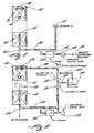
- a preformed mixing bag 700 is used in a system for the delivery of Celpure ® media to a filtration process wherein the suspension, slurry or solution is in the form of a Celpure ® media body-feed concentration produced with a process compatible solution.
- the mixing bag 700 has an interior mixing chamber 702 has a volume sufficient to receive a predetermined weight of dry material capable of being forming and remaining in suspension in a process compatible solution and a selected volume of process compatible solution to form a solution having the material in suspension with a selected concentration.
- a sealable opening 704 is provided for separately filling the mixing bag 700 with a dry powder at a remote location as described in Fig. 17 .
- the mixing bag 700 may be filled with a selected volume of Celpure ® media, e.g., Celpure ® 300 or Celpure ® 1000 offered for sale and sold by . , World Minerals, Inc., Santa Barbara; California.
- the preformed mixing bag 700 has a substantially rectangular shape and has three sealable opening, 704, 706 and 708. Opening 704 is dedicated as a filling port. Openings 706 and 708 function as the at least two sealable openings as described herein before.
- Appropriately sized peristaltic pumps depicted by elements 722, 724 and 726 are provided to perform the functions of injecting a process compatible solution into the interior mixing chamber 702 of mixing bag 700, agitating the solution and withdrawing the solution when a selected concentration is achieved.
- Line 730 extends from opening 708 to pump 720.
- Line 734 extends from opening 706 and is bifurcated to extend through a clamp 744 to pump 722 and to branch line 740 to clamp 748.
- Line 752 extends from clamp 748 to line 760 which extends between pump 720 and clamp 766.
- Line 770 extends between a source of feedstock or process compatible solution 772.
- Line 774 is connected to line 770 and extends to a clamp 776 located at the inlet of pump 724.
- Line-800 extends from pump 724 to line 802.
- Line 802 connects pump 722 to a filter 804 to perform the dynamic filtering of a designated fluid to be filtered.
- the mixing bag having the dry powder is placed into position and the apparatus is connected as described.
- the mixing bag may contain 5 kg of Celpure ® media which is to be used for the delivery of 5kg of Celpure ® media to a filtration process.
- the mixing bag holds up to 50L of suspension or solution which will produce a Celpure ® body feed concentration of 100 g/L.
- the suspension may be produced with a process compatible solution, e.g., water, or feedstock, e.g. whole yeast cells, mammalian cells and Lysed E. Coli cells.
- the solution at a selected concentrated may be pumped, either undiluted at 100 g/L, into the filter 804 or diluted with feedstock, via an inline mixer pump 724, to a lower target concentration, e.g. 2g/L.
- the mixing bag 700 is injected or filled with a process compatible fluid from source 772 using pump 720.
- Clamp 776 is closed to occlude line 774 and clamp 766 is opened providing the pump 720 with access to the source 772 through line 760, opened clamp 766 and line 770.
- the volume of process compatible solution would be about 48L.
- the pump 720 fills the mixing bag' at about 20L/min.
- the agitation step is then initiated. This is accomplished by closing clamp 766, opening clamp 748 and reversing flow of pump 720 at a flow rate of about 20L/min.
- the agitation time period is about 10 minutes to obtain the selected concentration of 100g/L.
- the solution Upon completion of the step of agitating the solution, the solution is ready to be withdrawn.
- the withdrawal is accomplished by opening clamp 744 to withdraw the solution at the selected concentration from line 740 using pump 722 through line 802 to the filter 804.
- Clamp 766 is occluded or closed and clamp 776 is open to enable pump 724 to controllably dilute the solution with the feed stock at an appropriate feed rate to obtain the desired lower target concentration.
- the mixing bag can be recycled for subsequent cycle, or if the mixing bag is a single use-mixing bag, the mixing bag is then discarded.
- the teachings of this invention include use of the mixing bag in a system.
- the system comprises a mixing bag having an interior-mixing chamber having a volume sufficient to receive a predetermined weight of dry powder and a selected volume of process compatible solution to form a solution having powder in suspension with a selected concentration and wherein the interior mixing chamber has a predetermined weight of dry powder stored therein.
- the interior-mixing chamber having a first end and a second end wherein the second end is located in an opposed spaced relationship to the first end.
- the mixing bag includes three sealable openings as indicated above
- the system includes a first conduit system 100 configured to be operatively removeably connected to the first sealable opening for enabling agitating of the solution of powder and process compatible solution in the interior mixing chamber to form a solution of the process compatible solution having the powder in suspension with a selected concentration.
- a second conduit system 102 is operatively removeably connected to the second sealable opening and to the first conduit system for enabling injection of a process compatible solution into the interior mixing chamber through the second opening to form a solution having powder in suspension, for enabling agitation of the powder and process compatible solution within the interior mixing chamber through the second opening to form a solution having powder in suspension with a concentration and for enabling withdrawal of solution from the interior mixing chamber with a selected concentration through the second opening.
- a pump 106 shown in Fig. 11 is operatively connected to the first conduit system 100 and to the second conduit system 102.
- the pump 106 is configured to at least one of injecting process compatible solution from a source of process compatible solution into.the interior chamber to form a solution having powder in suspension and agitating the solution of powder and process compatible solution within interior mixing chamber to form a solution having powder in suspension with a selected concentration.
- Withdrawal of the solution at the selected concentration may be performed using at least one of the first conduit system and the second conduit system as discussed hereinbefore.
- the system may further comprise a controller for controlling the pump to inject a selected volume of make-up process compatible solution from a source of process compatible solution into the interior-mixing chamber.
- the Examples include use of Celepure P65 ® media, Celepure 300 ® media and Celepure 1000 ® media.
- the specifications of the above Celpure ® media are set forth below for reference.
- Celepure P65 ® media is characterized as a Lightly Calcined, Purified Siliceous Earth, the specifications of which are as follows: Specification Properties Minimum Maximum Vel permeability (millDarcy 40 80 Centrifuged wet density (g/cm 3 ) - 0.26 PH (-Log [H]) 5 8 Conductivity ( ⁇ S/cm) - 15 Acid soluble iron (ppm) - 8 Citric acid ethanol soluble aluminum (ppm) - 8 Endotoxin - 1 National Formulary Maximum Moisture 105°C (%) 0.5 Ignition loss-dry (%) 2.0 Acid solubles (%) 2.0 Water-soluble substances (%) 0.2 Acid soluble iron (ppm) 10 Acid soluble iron lead (ppm) 10 Non-siliceous substances (mg) 50
- Celepure P100 ® media is characterized as a Calcined, Purified Siliceous Earth, the specifications of which are as follows: Specification Properties Minimum Maximum Vel permeability (millDarcy 70 140 Centrifuged wet density (g/cm 3 ) - 0.26 PH (-Log [H]) 5 8 Conductivity ( ⁇ S/cm) - 15 Acid soluble iron (ppm) - 8 Citric acid ethanol soluble aluminum (ppm) - 6 Endotoxin - - 1 National Formulary Maximum Moisture 105°C (%) 0.5 Ignition loss-dry (%) 2.0 Acid solubles (%) 2.0 Water-soluble substances (%) 0.2 Acid soluble iron (ppm) 10 Acid soluble iron lead (ppm) 10 Non-siliceous substances (mg) 50
- Celepure P300 ® media is characterized as a Lightly Calcined, Purified Siliceous Earth, the specifications of which are as follows: Specification Properties Minimum Maximum Vel permeability (millDarcy 150 300 Centrifuged wet density (g/cm 3 ) - 0.25 PH (-Log [H]) 5 8 Conductivity ( ⁇ S/cm) - 15 Acid soluble iron (ppm) - 5 Citric acid ethanol soluble aluminum (ppm) - 4 Endotoxin - 1 National Formulary Maximum Moisture 105°C (%) 0.5 Ignition loss-dry (%) 2.0 Acid solubles (%) 2.0 Water-soluble substances (%) 0.2 Acid soluble iron (ppm) 10 Acid soluble iron lead (ppm) 10 Non-siliceous substances (mg) 50
- Celepure P1000 ® media is characterized as a Lightly Calcined, Purified Siliceous Earth, the specifications of which are as follows: Specification Properties Minimum Maximum Vel permeability (millDarcy 750 1,250 Centrifuged wet density (g/cm 3 ) - 0.24 PH (-Log [H]) - 8.8 Conductivity ( ⁇ S/cm) - 15 Acid soluble iron (ppm) - 5 Citric acid ethanol soluble aluminum (ppm) - 4 Endotoxin - 1 National Formulary Maximum Moisture 105°C (%) 0.5 Ignition loss-dry (%) - 2.0 Acid solubles (%) 2.0 Water-soluble substances (%) 0.2 " Acid soluble iron (ppm) 10 Acid soluble iron lead (ppm) 10 Non-siliceous substances (mg) 50
- the following example utilizes Celepure 100 ® media.
- a preformed mixing bag having a structure illustrated in Fig. 1 and formed of a HyClone HyQ CX5-14 Film was used.
- the mixing bag had three (3) sealable openings.
- a tying member was affixed to the collar of the second sealable opening to prevent impaction of the dry powder in the collar.
- the solution was prepared using the five kilograms (5 kg) of Celepure P100 ® media stored in the mixing bag.
- the tying member affixed to the collar of the second sealable opening was removed.
- the second sealable opening and third sealable opening were unsealed.
- the first conduit system and the second conduit system were then operatively attached the first sealable opening and the second sealable opening, respectively.
- the make-up process compatible solution was injected through the second sealable opening.
- the total selected volume of process compatible solution injected into the interior mixing chamber was about 13 gallons (about 48 liters).
- the injection rate was about 5.3 gallons per minute (about 20L/minute).
- a peristaltic pump Upon injection of the selected volume of liquid into the interior-mixing chamber, a peristaltic pump was used to provide the desired agitation through the second and third sealable openings.
- the reversible pump agitation was at the rate of about 3 gallons per minute (about 10L/minute) with size .75 inch ID tubing.
- the filter was a standard process compatible solution filter to remove impurities and had a through put capability equal to the pump flow rate.
- the time period for agitation was about ten (10) minutes.
- the solution was agitated to form a solution having dry powder in suspension with a selected concentration of 100g/L.
- Packaging configurations for the mixing bag used in the method of the present invention and materials filled therein for practicing this invention come in a variety of sizes for non-bulk options.
- the preformed mixing bag can be fabricated to be a round shape, square shape, rectangular shape, oblong shape, conical shape, elliptical shape, triangular shaped or other geometrical shape.
- the bottom of the mixing bag can be fabricated to be slopped, conical shaped, flat or other appropriate shape to support the dry powder in the mixing bag.
- the mixing bag when placed into a shipping container, assumes the shape of the container.
- the shipping container may be fabricated to include a preformed shipping support member formed in the bottom member thereof or, in the alternative, may include a separate insertable shipping support member which is placed in the bottom of the shipping container prior to inserting of the mixing bag (filled or unfilled) into the shipping container.
- a preformed shipping support member formed in the bottom member or a separate insertable shipping support member functions to provide a means for enabling the mixing bag and dry powder to assume the shape of the holder.
- Such non-bulk options include mixing bags formed of plastic materials, poly materials, Hyclone films, e.g. HyQ CX5 Film, or other appropriate chemically and physically compatible materials, as is well known to persons skilled in the art.
- the weights of dry powder could be in the 5 kg to 15 kg range of weights of dry powder using a mixing bag formed of poly materials and the weights of dry powder weights in the range of 10 kg to 22.5 kg range of weights of dry powder using a mixing bag formed of HyClone films, e.g.
- Sterile Fluid handling bags for medical applications and mixing bags for industrial and other applications as discussed above are typically constructed of multi-layer film(s).
- the following are typical materials utilized in the manufacture of multi-layer films suitable for use in mixing bags and are shown in Table D: Table D Identification of Layer Characteristic of Layer Fluid Contact Layer Offers excellent Ultra Low Density Polyethylene biocompatibility as well as chemical compatibility with a wide range of solutions.
- (ULDPE) Gas Barrier Layer Provides outstanding performance as a barrier to atmospheric gasses.
- Ethyl Vinyl Alcohol (EVOH) Strength Layer Offers excellent strength properties for bags that have. the potential to be used or manipulated outside a cylindrical tank or tote Nylon (NYLON) Tie Layer Materials provide outstanding layer fusion. Materials contribute to overall bag strength and gas barrier properties.
- Table E Material A Application Description Sterile Fluid Layer 1-NYLON Handling Bags Layer 2-TIB Layer 3-EVOH Layer 4-TIE Layer 5-ULDPE B Sterile Fluid Layer 1-NYLON Inner Film Layers Handling Bags Layer 2-TIE Layer 3-EVOH Layer 4-TIE Layer 5-ULDPE Outer Film Layers Layer 6-TIE Layer 7-ULDPE Layer 8-ULDPE C Large Layer 1-TIE Container Bags Layer 2-ULDPE Layer 3-ULDPE D Cassette Bags Layer 1-ULDPE Inner Film Layer 2-ULDPE Barrier Film Layer 3-ULDPE Outer Film Layers Layer 4-EVOH Layer 5-ULDPE
- the mixing bags used in the method of the present invention may comprise single layer film or multilayer films depending on the application and engineering requirements for the bag.
- the materials used for fabricating the mixing bag can be selected to maximize performance of the mixing bag.
- the product there are three (3) important dry powder material, referred to as the product, aspects which remain substantially constant in the solution and during the process of forming the solution.
- the three (3) important dry powder material product aspects are as follows: (i) the solution maintains substantially the same product density when used in an application, e.g., as a filter cake when the solution is used as a filter aid; (ii) the permeability of the product in solution remains substantially unchanged; and (iii) the integrity of the product in solution remains substantially the same, e.g., the structure of the material product does not substantially decompose or break down into smaller particles during formation of the solution.
- One attribute of forming a solution using a selected dry material using, the teachings of the present invention, is that the process of forming the solution, including agitation thereof, does not significantly degrade the critical physical characteristics of the dry powder material product which is essential in an application using the solution which relies on the critical physical characteristics of the material product in solution remaining substantially unchanged to perform a desired function.
- the dry material used may be a Celpure ® Diatomite that is to be used as a filter aid.
- the fundamental intricate, fine particulate, and porous structure of the diatom frustule forming the Celpure ® Diatomite gives diatomite its low density, high surface area, high porosity and permeability. These attributes give diatomite its unique commercial value and versatility unmatched by other natural forms of silica for certain applications, e.g. in filtration applications.
- diatomite may be processed to impart a specific permeability range which is of general importance in solids-liquids separation applications.
- diatomite products In the field of filtration, many methods of particle separation from fluids employ diatomite products as filter aids.
- diatomite products The intricate and porous structure unique to diatomite silica is particularly effective for the physical entrapment of particles in filtration processes. It is common practice to employ diatomite products when improving the clarity of fluids that contain suspended particles or particulate matter, or have turbidity.
- diatomite products are usually processed to provide a range of filtration rates, which are closely related to their permeability.
- Permeability is reported in units of Darcies, as discussed hereinbefore, and is commonly abbreviated "Da”.
- the permeability, in Da is readily determined (European Brewery Convention, 1987) using a specially constructed device designed to form a filter cake on a septum from a suspension of diatomite in water, and then measuring the time required for a specified volume of water to flow through a measured thickness of.filter cake of known cross-sectional area.
- the principles have been previously derived for porous media from Darcy's law (Bear, 1972), so an array of alternative devices and methods are in existence that correlate well with permeability.
- Diatomite filter aids that are currently commercially available span a wide range of permeability, from about 0.001 Da to about 30 Da.
- the selection of a filter aid with a particular permeability suitable for a specific filtration process depends on the flow rate and degree of fluid clarification desired for the particular application.
- using a dry powder with a known or selected permeability which remains substantially unchanged during preparation of the solution using the dry powder in accordance with the teachings of this invention is one of the desired attributes of this invention.
- the dry material used may be LRA ® , Celpure ® , and Chromosorb ® designed to be used as Sorbents and Chromatography Media.
- a sorbent's usefulness is in removing soluble constituents from biologic and non-biologic solutions and the desired criteria for using the same can be traced to its surface area, density, or other physical attributes that effect the mass transfer of solutes in solution.
- the mixing bag interior mixing chamber has a volume sufficient to receive a predetermined weight of dry material capable of being forming and remaining in suspension in a process compatible solution and a selected volume of process compatible solution to form a solution, suspension or slurry having the material in suspension with a selected concentration or select density or a density within a range of selected densities.
- the dry material can be a granulated or powder concentrate capable of forming a solution. It is preferable that the powder be as dry as possible.
- the teachings of the present invention can be used with a slightly hydrated media. A more wet or the heavier hydrated media makes it more difficult it becomes to break up the particles to form the desired solution, suspension or slurry. Injecting of the process compatible solution from the bottom of the mixing bag enhances the formation of the desired solution, suspension or slurry, particularly with a dry medium or a slightly hydrated media.
- the mixing bag can be used in the industrial field for producing solutions used in making filter aids; in the agriculture field for fertilizers, pesticides, gypsum; in the medical field for kidney dialysis and in the food and beverage industry for making solutions from dry powder for use as beverages or the like.
- United States Patent 5,121,857 discloses agitating apparatus for dispensing fruit juices from a bag in a box arrangement wherein the a metalized plastics material flexible bag containing a fruit drink having fruit particles suspended therein.
- the mixing bag of the present invention can be used with such agitating and dispensing apparatus in the beverage industry.
- the dry powder is a non-soluble powder.
- the non-soluble powder maybe be selected from a group consisting of diatomaceous earth, Celepure P65 ® media, Celepure P100 ® media, Celepure 300 ® media, Celepure P1000 ® media, LRA ® media and sorbents.
- the dry powder may be a Sorbent.
- a Sorbent is associated with Sorption. Sorption is the association of a gas phase or aqueous substance with a solid material, known as the sorbent, by surface attachment (adsorption) or dissolution and migration into the solid phase (absorption).
- Solid phase refers to material that behaves as a solid according to macroscale measures. At a chemical level, the surface of that solid may act more like an oil film.
- Adsorption refers to association of a sorbate with surfaces.
- “Absorption” implies penetration of a sorbate into the sorbent , by diffusion.
- the dry powder can be used for Chromatography.
- chromatography is a separation process that is achieve by distributing the substances to be separated between a mobile phase and a stationary phase. Those substances distributed preferentially in the moving phase pass through the chromatographic system faster than those that are distributed preferentially in the stationary phase. As a consequence, the substances are eluted from the column inverse order of their distribution coefficients with respect to the stationary phase.
- LRA ® , Celpure ® , and Chromosorb ® can all be called chromatography media, sorbents, or filter aids.
- LRA ® is not a diatomite, however it.is a silicate. Chromosorb products are a mix. Some are solely diatomite, some are diatomite coated with polymers (e.g. Teflon) and some are pure polymers.
- the teachings of the present invention has utility for the hydrating of chromatography media in a mixing bag and the withdrawal of and loading of chromatography media at a concentrated solution from the mixing bag into chromatography media columns in the same manner as a Celepure ® media is used as a filter aid as described herein.
- FIG. 21 another embodiment or species of a preformed mixing bag used in the method of the invention in the form of a bioprocess container 900 configured for use in pharmaceutical applications is shown.
- the bioprocess container 900 has three sealable inlets or openings 904, 906 and 908.
- the three sealable inlets or openings 904, 906 and 908 could be used to inject a process compatible fluid (or a feedstock solution or make-up water) to be processed to form the solution, for agitating the solution and/or withdrawing the solution from the bioprocess container, according to the method of the invention.
- sealable inlet or opening 906 is used to fill the interior mixing chamber of the bioprocess container 900 having a volume sufficient to receive a predetermined weight of substantially dry material capable of remaining in suspension in a process compatible solution and a selected volume of process compatible solution to form a solution having the material in suspension with a selected concentration. If desired, a feed stock solution or fluid could be injected into the interior chamber of the bioprocess container through sealable inlet or opening 904.
- sealable inlet or opening 908 is used for at least one of injecting a process compatible fluid to be processed to form the solution, agitating the solution of powder and process compatible solution in the interior mixing chamber to form a solution of the process compatible solution having the powder in suspension with a selected concentration and/or for withdrawal of the solution with a selected concentration from the interior mixing chamber of the bioprocess container 900.
- a first conduit system 912 shown in Figs. 21 and 22 , is operatively removeably connected to the sealable inlet or opening 904 for injecting a feedstock solution, if desired, and/or agitating the solution of powder and process compatible solution in the interior mixing chamber to form a solution of the process compatible solution having the powder in suspension with a selected concentration in the presence of a feed stock material.
- the first conduit system 912 has a distal end 920 terminating in an insertion sleeve 924 that removably couples to extension 926 of opening 904.
- the distal end 920 may be a flexible section to facilitate easy coupling of insertion sleeve 924 with extension 926.
- a second conduit system shown in Fig. 23 is operatively removeably connected to sealable inlet or opening 906 for enabling filling of a dry powder into the interior of the bioprocess mixing bag.
- a closeable bag or cover 928 protects a coupling member depicted by arrow 930 during storage or shipment.
- the second conduit system 932 has a distal end 934 terminating in an insertion sleeve 936 which removeably couples to extension 938 of opening 906.
- a closeable bag or cover 942 protects a coupling member depicted by arrow 944 during storage or shipment.
- Fig. 24 is a top plan view of a third conduit system 948 shown in Fig. 21 and the third conduit system 948 is operatively removeably connected to sealable inlet or opening 908 for at least one of injecting process compatible solution into the interior mixing chamber to form a solution having powder in suspension, for enabling agitation of the powder and process compatible solution in the interior mixing chamber to form a solution having powder in suspension with a selected concentration and in cooperation with the first conduit system and/or enabling withdrawal of the solution with a selected concentration from the interior mixing chamber of the bioprocess container 900.
- the third conduit system 948 has a distal end 950 terminating in an insertion sleeve 952 which removeably couples to extension 956 of opening 908.
- a closeable bag or cover 960 protects a coupling member depicted by arrow 962 during storage or shipment.
- Fig. 25 is a top plan view of the second conduit system 932 of Fig. 23 and a vent filter 964 operatively connected to the second conduit system 932 for controlling dust and/or degassing of the bioprocess container 900.
- the vent filter has a first end 970 which is configured to cooperate with the connecting member 944 such that fluid flow is in the direction of into the interior chamber as shown by arrow 976.
- the vent filter may have a filter size of about .7 microns to about 5 microns for a bioprocess application.
- the bioprocess container has an interior-mixing chamber configured to receive a predetermined weight of dry powder, e.g. a predetermined volume of diatomaceous earth.
- Sealable inlet or opening 906 is preferably used for filling the interior chamber with a predetermined volume of dry material.
- Sealable inlet or opening 908 is used to inject the process compatible fluid and/or a feedstock solution into the interior mixing chamber and sealable openings 904 at 908 are used to agitate the solution using a pump or other means as discussed above in connection with Fig. 8 , 9 and 10 .
- the sealable inlet or opening 908 opening is used for withdrawing solution with a selected concentration, or selected solution density or a solution density which is within a density range of acceptable solution densities.
- the selected solution density and density range of the solution' and batch mixing specifications are determined by the requirements of the end user.
- the invention illustratively disclosed or claimed herein suitably may be practiced in the absence of any element which is not specifically disclosed or claimed herein.
- the invention may comprise, consist of, or consist essentially of the elements disclosed or claimed herein.
Landscapes
- Health & Medical Sciences (AREA)
- Heart & Thoracic Surgery (AREA)
- Urology & Nephrology (AREA)
- Life Sciences & Earth Sciences (AREA)
- Animal Behavior & Ethology (AREA)
- General Health & Medical Sciences (AREA)
- Public Health (AREA)
- Veterinary Medicine (AREA)
- Vascular Medicine (AREA)
- Emergency Medicine (AREA)
- Engineering & Computer Science (AREA)
- Anesthesiology (AREA)
- Biomedical Technology (AREA)
- Hematology (AREA)
- Chemical & Material Sciences (AREA)
- Chemical Kinetics & Catalysis (AREA)
- Pharmacology & Pharmacy (AREA)
- Processing And Handling Of Plastics And Other Materials For Molding In General (AREA)
- Mixers With Rotating Receptacles And Mixers With Vibration Mechanisms (AREA)
- Apparatus Associated With Microorganisms And Enzymes (AREA)
- Accessories For Mixers (AREA)
Abstract
Description
- This application claims Convention priority and priority under 35 U.S.C. § 119(e) to
U.S. Patent Application No. 60/475,658 - This application claims Convention priority to and is a U.S. continuation-in-part of
U.S. Patent Application No. 10/454,173 - This application claims Convention priority to and is a U.S. continuation-in-part of a new U.S. patent application that was filed on 28 May 2004 and that is entitled "Preformed Mixing Bag for Dry Powder, Apparatus, Method and System for Using Same." (The serial number for this new application is not yet known.).
- The present invention relates to a method comprising the use of a defined mixing bag for packaging, storing and shipping (using a separate shipping container) a dry material to be mixed in the mixing bag; more particularly the method of the invention comprises the use of a defined preformed mixing bag adapted to store a dry powder which is to be mixed with a process compatible solution to form a suspension of powder in the solution having the material in suspension with a selected concentration which may be at least one of a high concentration capable of being diluted to a target concentration or at a target concentration intended for use without being diluted.
- The use of mixing bags for storing a dry powder to be mixed in the mixing bag with a liquid is known in the art. The following prior art discloses typical mixing bags, apparatus and method for using such mixing bags.
- United States Patent
5,616,305 discloses a bag containing a selected quantity of dry powdered material wherein the volume of the bag is sufficient to add a liquid of a known maximum volume resulting in a solution in the form of a powdered salt concentrate wherein the solution is mixed by use of a pump connected to a water supply line. The powdered salt partially dissolves when the bag is completely filled with water. - United States Patent
5,643,585 discloses a non-soluble articulate coloring material comprising dry ground red micro algae-derived material as a base color material. The non-soluble particulate matter was stored in a transparent plastic bag for testing as opposed to mixing with a fluid. -
- United States Patent
5,362,642 discloses a cell culture media containment system having a mixing bag substantially enclosed within a storage bag powdered cell culture media and other constituents are introduced into the mixing bag and are mixed therein. Therefore, the reconstituted media is conveyed from the mixing bag into the storage bag. The mixing bag has an access port in the top to assist in the introduction of constituents into the mixing chamber and an introduction plate in the top having an opening allowing for insertion of tubes there through into the mixing chamber. The storage bag has an introduction plats having an opening for possessing tubing into the storage bag and to support a discharge tube. - United States Patent
5,121,857 discloses a system for agitating and dispensing a mixture from a bag-in-box arrangement wherein the bag-in-box has a connector having an inlet port, an outlet port and a pump. - United States Patent
5,709,467 discloses a bag or a pouch for mixing and dispensing an alginate and water composition and wherein the pouch or bag as a sealable opening. - United States Patent
6,298,984 discloses a package containing a medium that must be combined with an activator and mixed before the medium can be used by an end user. - United States Patent
4,948,013 discloses a method of mixing a powder and a fluid wherein a filter is used to allow only predetermined particles to be dispensed. -
- United States Design Patent Number DES
413,258 discloses a flexible bag in the form of a dunnage bag having a valve, the dunnage bag apparently being used for personal storage of fluids or personal belongings. - United States Design Patent Number DES 308,164 discloses a flexible container having an extended pouring spout for storing and dispensing fluids.
- United States Design Patent Number DES 304,546 discloses a flexible container having an opening which appears to be used for a filling the container with a fluid causing expansion of a bottom seam to accommodate a pre-determined volume fluid and wherein the opening is used to dispense the fluid.
- European Patent Office EPO Publication Number
0 152 283 discloses apparatus for dispensing a beverage from a reservoir wherein the reservoir containing the fluid is releasably connected to the apparatus wherein a pump continuously circulates the beverage around a fluid circuit. One or more dispensing valves or taps are located in the fluid circuit from which the beverage is to be dispensed. A metering pump is provided to effect mixing of the beverage within the reservoir when the beverage is to be formed of two or more liquids. -
- Discloses a system for preparation and use of dialyses solution United States Patent
5,3-85,564 . Having a bag which is constructed to hold granulated or powder concentrate. The bag has a V-shaped bottom with an access port in the bottom. Water is flowed through the access port and into the bag using water control means having a pump. The incoming water lifts and suspends the granules or powder. The filling of the bag is monitored by trip switches operatively attached to support the weight of the bag and contents. When the bag is filled sufficiently with water, the weight of the bag and contents trips the trip switches and a signal is sent to deactivate the pumps through control circuits. -
DE-A-10100549 discloses a salt concentrate container for dialysis apparatus, with 2 openings connected to a liquid circuit, wherein the salt concentrate is soluble in the dialysis liquid.EP-A-0619135 discloses a system for preparing a fluid for medical treatment by dissolving a first compound (such as a saline concentrate) in a second compound (such as an haemodialysis fluid), the system comprising the use of a specific ultrasound generator for assisting dissolution. - More specifically, the document
EP-A-0619135 discloses a method comprising the use of a mixing bag having an interior mixing chamber having a first end located in a top section and a second end located in a bottom section and having a predetermined weight of a first compound (such as saline concentrate), said mixing bag having: - a first sealable opening extending from a location exterior to the mixing bag and into communication with the interior mixing chamber at said first end and which is configured for at least one of enabling transportation of the first compound into the interior mixing chamber, enabling agitation of the first compound with a second compound (such as water) in the interior mixing chamber to form a solution and enabling withdrawal of the solution from the interior mixing chamber;
- a second sealable opening extending from a location exterior to the mixing bag and into communication with the interior mixing chamber at said second end and which is configured for at least one of enabling injection of the second compound into the interior mixing chamber to form a solution, enabling agitation of the first and second compounds in the interior mixing chamber to form a solution and enabling withdrawal of the solution from the interior mixing chamber; and
- a third sealable opening extending from a location exterior to the mixing bag and into communication with the interior mixing chamber and which is configured for enabling transporting the first compound into the interior mixing chamber.
- The present invention is directed to a method comprising the use of a mixing bag, as defined in
claim 1. The method of the invention enables mixing a dry powder with a process compatible solution in a preformed mixing bag to form a suspension of powder in the process compatible solution having the material in suspension with a selected concentration which is at least one of a high concentration capable of being diluted to a target concentration and a target concentration or, in the alternative, a selected density or a density within or acceptable range of densities. The mixing bag, which may be a preformed mixing bag, comprises an interior mixing chamber having a volume sufficient to receive a predetermined weight of dry powder and a selected volume of process compatible solution to form a solution having powder in suspension with a selected concentration, e.g. g/L or selected density e.g. g/L3. The selected concentration is at least one of a high concentration capable of being diluted to a target concentration and a target concentration. - The dry powder may be for example a Celpure® media or e.g. a slightly hydrated media such as for example an LRA® media.
- The selected concentration may be at a high concentration of Celpure® media or LRA® media, e.g. 100 g/L, to minimize the size of the system and the resulting solution may then be diluted with an inline mixer to achieve a lower target concentration, e.g. 2g/L.
- Therefore, it is an advantage of the present invention to provide the use of a mixing bag having a volume sufficient to receive a predetermined weight of dry material capable of being forming and remaining in suspension in a process compatible solution and a selected volume of process compatible solution to form a solution having the material in suspension with a selected concentration or selected solution density.
- Another advantage of the present invention is that the mixing bag can be used in methods, apparatus and a system for forming a solution having the material in suspension with a selected concentration which is at least one of a high concentration capable of being diluted to a target concentration and a target concentration intended for use without being diluted.
- Another advantage of the present invention is that the selected concentration of the solution may be a high concentration to minimize system size and the resulting solution may then be diluted to achieve a lower target concentration.
- Another advantage of the present invention is that a mixing bag can be a preformed mixing bag having a selected shape.
- Another advantage of the present invention is that the mixing bag can be have a volume sufficient to receive a predetermined weight of dry material capable of being forming and remaining in suspension in a. process compatible solution and a selected volume of a process compatible solution to form a solution having the material in suspension with a selected concentration.
- Another advantage of the present invention is that the mixing bag can be have a volume sufficient to receive a predetermined weight of non-soluble powder capable of being forming and remaining in suspension in a process compatible solution and a selected volume of process compatible solution to form a solution having the material in suspension with a selected concentration. In the preferred embodiment, the non-soluble powder is diatomaceous earth. In alternative applications, the non-soluble powder may comprise Celpure® media, LRA® media or sorbents.
- Another advantage of the present invention is that the mixing bag can have an outer member having a predetermined shape and a sidewall defining an interior mixing chamber having a volume sufficient to receive a predetermined weight of dry powder and a selected volume of process compatible solution to form a solution.
- Another advantage of the present invention is that the mixing bag can have an outer member which is in the shape of an elongated thin walled rectangular member having a hollowed-out passageway defining the interior mixing chamber.
- Another advantage of the present invention is that the mixing bag can have an outer member which is in the shape of an elongated thin walled cylindrical member having a hollowed-out passageway defining the interior mixing chamber.
- Another advantage of the present invention is that the mixing bag can have an outer member which is in the shape of an elongated thin walled cylindrical member having a hollowed-out passageway defining the interior mixing chamber wherein the interior mixing chamber includes an internal conical shaped hopper for receiving dry powder.
- Another advantage of the present invention is that the mixing bag comprises a third sealable opening which is configured for enabling transporting dry powder into the interior mixing chamber; a second sealable which is configured for at least one of enabling injection of process compatible solution into the interior mixing chamber to form a solution having the powder in suspension, enabling agitation of the powder and process compatible solution in the interior mixing chamber to form a solution having the powder in suspension with a selected concentration and enabling withdrawal of the solution with a selected concentration from the interior mixing chamber; and a first sealable opening which is configured for enabling at least one of agitation of the powder and process compatible solution in the interior mixing chamber to form a solution having the powder in suspension with a selected concentration, and enabling with drawal of the solution with a selected concentration from the interior mixing chamber.
- The method of the invention comprises the steps of injecting a selected volume of process compatible solution, e.g. water or feedstock solution, into a mixing bag through the second sealable opening; agitating through at least one of said first and second sealable openings the powder and process compatible solution in the interior mixing chamber to form a solution having powder in suspension with a selected concentration and withdrawing from the interior mixing chamber through at least on of said first and second sealable openings the solution with a selected concentration. The selected concentration is at least one of a high concentration capable of being diluted to a target concentration and a target concentration intended for use without being diluted.
- Another advantage of the present invention is that the mixing bag having an interior mixing chamber having a predetermined weight of dry powder, e.g. a predetermined volume of diatomaceous earth, can be fabricated as a bioprocess container having three sealable inlets or openings. The three sealable openings can be used for a number of functions. The second sealable opening can be used for injecting a process compatible solution and/or a feedstock solution into the interior mixing chamber. As such, a selected volume of process compatible solution, e.g. make-up water or feedstock solution, can be injected into the container to form a solution comprising diatomaceous earth in suspension with a selected concentration, or selected solution density or a solution density which is within a density range of acceptable solution densities. The first and second sealable inlets or openings can be used to provide fluid flow for agitating or mixing the solution, for having a vent filter placed in line or for withdrawing solution with a selected concentration, or selected solution density or a solution density which is within a density range of acceptable solution densities. The selected solution density and density range of the solution and batch mixing specifications are determined by the requirements of the end user. The first and second sealable openings are provided to with draw the solution from the mixing bag.
- The present invention will become more fully understood from the following detailed description of a preferred but nonlimiting embodiment thereof, described in connection with the accompanying drawings, wherein:
-
Fig. 1 is a front, left side and top perspective view of a preformed mixing bag, having a top section and a bottom section, adapted to store a dry material, e.g. dry powder in an interior mixing chamber which is to be mixed with a process compatible solution to form a suspension of powder in the solution having the material in suspension with a selected concentration and wherein the preformed mixing bag has at least two sealable openings; -
Fig. 2 is a perspective pictorial representation of a shipping container having placed therein a preformed mixing bag ofFig. 1 filled with a predetermined weight of dry powder for shipping to an end user for subsequent injection of a process compatible solution into the interior mixing chamber to form a solution having powder in suspension; -
Fig. 3 is a front elevational view of a preformed mixing bag ofFig. 1 showing the second sealable opening for at least one of enabling injection of a process compatible solution into said interior mixing chamber to form a solution having powder in suspension, enabling agitation of the powder and process compatible solution within the interior mixing chamber to form a solution having powder in suspension with a selected concentration, and enabling withdrawal of the solution with a selected concentration from the interior mixing chamber; -
Fig. 4 is a top plan view of the preformed mixing bag ofFig. 1 showing the third sealable opening configured for enabling transporting a predetermined weight of dry powder into the interior mixing chamber and the first sealable opening for enabling at least one of agitation of the powder and process compatible solution within the interior mixing chamber to form a solution having powder in suspension with a selected concentration and enabling withdrawal of solution from the interior mixing chamber at a selected concentration and wherein the preformed mixing bag can optionally include an auxiliary opening which can be used as required; -
Fig. 5 is a back elevational view of a preformed mixing bag ofFig. 1 showing the third sealable opening configured for enabling transporting a predetermined weight of dry powder into the interior mixing chamber and the first sealable opening for at least one of enabling agitation of the powder and process compatible solution within the interior mixing chamber to form a solution having powder in suspension with a selected concentration and enabling withdrawal of solution from the interior mixing chamber at a selected concentration; -
Fig. 6 is a bottom plan view of the preformed mixing bag ofFig. 1 showing the second sealable opening for at least one of enabling injection of a process compatible solution into said interior mixing chamber to form a solution having powder in suspension, enabling agitation of the powder and process compatible solution within the interior mixing chamber to form a solution having powder in suspension with a selected concentration and enabling withdrawal of solution from the interior mixing chamber at a selected concentration; -
Fig. 7 is a pictorial representation of the of the mixing bag ofFig. 1 showing a preformed mixing bag having a first sealable opening, a second sealable opening, a third sealable opening and an auxiliary opening, the relationship between and functions of the first, second and third sealable openings and use of the first sealable opening for enabling transporting of a predetermined weight of dry powder into the interior mixing chamber; -
Fig. 8 is a pictorial representation of the of the mixing bag ofFig. 1 showing a preformed mixing bag having a first sealable opening, a second sealable opening, a third salable opening and an auxiliary opening, the relationship between and functions.of the first, second and third sealable openings for enabling transporting a predetermined weight of dry powder into the interior mixing chamber, enabling injection of a process compatible solution into the interior mixing chamber to form a solution having powder in suspension, enabling agitation of the powder and process compatible solution to form a solution having powder in suspension with a selected concentration and enabling withdrawal of the solution from the interior mixing chamber with a selected concentration under control of a mixing control system having a computer system; -
Fig. 9 is a pictorial representation of the of the mixing bag ofFig. 1 having a first sealable opening, a second sealable opening, third sealable opening and an auxiliary opening showing the use of the second salable opening for enabling injection of a process compatible solution into the interior mixing chamber through the bottom section of the mixing bag to form a solution having powder in suspension; -
Fig. 10 is a pictorial representation of the of the mixing bag ofFig. 1 having a first sealable opening, a second sealable opening, a third sealable opening and an auxiliary opening showing the use of the second salable opening and the first sealable' opening for enabling agitation of the powder and process compatible solution to form a solution having powder in suspension with a selected concentration, enabling filtering of the solution and for enabling withdrawal of the solution from the interior mixing chamber with a selected concentration through a filter feedstock conduit under control of a mixing control system; -
Fig. 11 is a diagrammatic representation of a mixing bag of the present invention having a source of dry powder, a first conduit system and a second conduit system including showing in dashed lines connecting hoses, a pump, a filter and a controller for controlling the injecting of make-up, process compatible solution of a selected volume into the interior mixing chamber and for withdrawing of solution from the interior mixing chamber at a selected concentration; -
Fig. 12 is a top plan view of the first conduit system shown inFig. 11 operatively removably connected to one of the first and second openings for enabling agitating the solution of powder and process compatible solution in the interior mixing chamber to form a solution of the process compatible solution having the powder in suspension with a selected concentration; -
Fig. 13 is a top plan view of the second conduit system shown inFig. 11 operatively removeably connected to the second opening for at least one of injecting process compatible solution into the interior mixing chamber to form a solution having powder in suspension, enabling agitation of the powder and process compatible solution in the interior mixing chamber to form a solution having powder in suspension with a selected concentration and in cooperation with the first conduit system enabling withdrawal of the solution with a selected concentration from the interior mixing chamber; -
Fig. 14A is an exploded front elevational view of the third sealable opening having a port assembly with a sealing cap for enabling transporting a predetermined weight of dry powder into the interior mixing chamber of a mixing bag and sealing of the port assembly; -
Fig. 14B is an exploded front elevational view of the third sealable opening having a port assembly with an elongated attachment member for enabling transporting a predetermined weight of dry powder into the interior mixing chamber of a mixing bag through the elongated attachment member; -
Fig. 15 is a pictorial representation of yet another embodiment or a preformed mixing bag for practicing the teachings of the present invention wherein a magnetically controlled impeller is used for agitating the solution; -
Fig. 16 is a pictorial representation of a magnetically controlled impeller configured for use in the embodiment illustrated inFig. 15 ; -
Fig. 17 is a block diagram of the method for filling a preformed mixing bag having an interior mixing chamber configured to have a volume sufficient to receive a predetermined weight of dry powder and a selected volume of process compatible solution to form a solution having powder in suspension with a selected concentration and shipping the same in a shipping container to an end user; -
Fig. 18 is a block diagram of the method for using a preformed mixing bag having an interior mixing chamber containing a predetermined weight of dry powder wherein the sealable openings are unsealed for enabling injection of a process compatible solution into the interior mixing chamber to form a solution having powder in suspension, enabling agitation of the powder and process compatible solution to form a solution having powder in suspension with a selected concentration and enabling withdrawal of the solution from the interior mixing chamber with a selected concentration or at a desired concentration; -
Fig. 19 is a pictorial representation of another embodiment of a preformed mixing bag having a conical shaped internal hopper for practicing the teachings of the present invention; -
Fig. 20 is a pictorial representation of another embodiment of a preformed mixing bag in a system for the delivery of Celpure® media to a filtration process wherein the suspension produces a Celpure® media body-feed concentration produced with a process compatible solution; -
Fig. 21 . is a pictorial representation of another embodiment/species of a preformed mixing bag in the form of a bioprocess container having three sealable inlets or openings used to inject a process compatible fluid (or a feedstock solution or make-up water) to be processed to form the solution, for agitating the solution and/or withdrawing the solution from the bioprocess container, -
Fig. 22 is a top plan view of a first conduit system shown inFig. 21 operatively removeably connected to the first sealable inlet or opening for agitating the solution of powder and process compatible solution in the interior mixing chamber to form a solution of the process compatible solution having the powder in suspension with a elected concentration in the presence of a feed stock material; -
Fig. 23 is a top plan view of a second conduit system shown inFig. 21 operatively removably connected to the third sealable inlet or opening for enabling filling of a dry powder into the interior of the bioprocess mixing bag, -
Fig. 24 is a top plan view of a third conduit system shown inFig. 21 operatively removeably connected to the second sealable inlet or opening for at least one of injecting process compatible solution into the interior mixing chamber to form a solution having powder in suspension, for enabling agitation of the powder and process compatible solution in the interior mixing chamber to form a solution having powder in suspension with a selected concentration and in cooperation with the first conduit system and/or enabling withdrawal of the solution with a selected concentration from the interior mixing chamber; and -
Fig. 25 is a top plan view of the second conduit system ofFig. 23 and a vent filter operatively connected to the second conduit system for controlling dust and/or degassing of the bioprocess container. - Before proceeding with the description of the preferred embodiment, the following background will be helpful in understanding this invention.
- Dynamic depth filtration, also known as pressure precoat filtration, is a constant flow, solid-liquid separation technique that has been practiced for over 75 years. Dynamic depth filtration uses a primary filter media that is a high purity, high-performance diatomite filter aid. Diatomite is a silica powder composed of diatoms, which are rigid, porous and irregular in shape, and Diatomite is essentially a dense, chert-like, consolidated diatomaceous earth.
- Diatomaceous earth is well known in the art and is made of opaline shells of diatoms and has a consistency of dry powder. Diatomaceous earth has a wide variety of uses including, without limitation, uses as a filter aid, paint additive, sorbent, abrasive and thermal insulator. Diatomaceous earth is also known as kieselguhr and tripolite.
- The use of the term "diatomaceous earth" as used herein is intended to cover all of the above-described materials.
- In the field of filtration, many methods of particle separation from fluids employ diatomite products as filter aids. The intricate and porous structure unique to diatomite silica is particularly effective for the physical entrapment of particles in filtration processes. It is common practice to employ diatomite products when improving he clarity of fluids that contain suspended particles or particulate matter, or have turbidity.
- Diatomire products are often applied to a septum to improve clarity and increase flow rate in filtration processes, in a step sometimes referred to as "precoating." Diatomite is also often added directly to a fluid as it is being filtered to reduce the loading or plugging of undesirable particulate at the septum while maintaining a designed liquid flow rate, in a step often referred to as "body feeding." Depending on the particular separation involved, diatomite products may be used in precoating, body feeding, or both. The principles involved with Diatomite filtration have been reviewed (Kiefer, 1991).
- In some filtration applications, different diatomite products are blended together to further modify or optimize the filtration process. Also, diatomite products are sometimes combined with other substances. In some cases, these combinations may involve simple mixtures, for example, with cellulose, activated charcoal or carbon, clay, or other materials. In other cases, these combinations are composites in which diatomite products are intimately compounded with other ingredients to make sheets, pads, or cartridges. Still more elaborate modifications of any of these diatomite products are used for filtration or separation, involving, for example, surface treatment and the addition of chemicals to diatomite products, mixtures, or their composites.
- In certain circumstances, diatomite products may also exhibit unique absorptive properties during filtration that can greatly enhance clarification or purification of a fluid. These adsorptive properties are highly specific, and depend upon weak forces for attraction of the absorbed species to weak electrical charges at the surface of diatomite, or upon the reactivity of silanol (i.e., =Si-OH) functional groups that often occur at the diatomite surface. For example, an ionized silanol group (i.e., =Si-0-) may react with a hydroniumion (i.e., H,0+) contributed by an acidic substance in solution, for example, citric acid (i.e. C6H8O7), adsorbing the donated H+ at the surface in the Process.
- In filtration applications, diatomic products are usually processed to provide a range of filtration rates that are closely related to their permeability reported in units of Darcies. Diatomic filter aids are available in a wide range of permeabilities. The selection of a filter aid with a particular permeability suitable for a specific process depends on the flow rate and degree of fluid clarification desired for the particular application.
- Darcy's Law is well known to persons skilled in the art and is essentially an empirical law that governs flow through porous media and describes the relationship among flow rate, pressure drop and resistance. Functional filtration rates products are usually processed to provide a. range of filtration rates that are closely related to their permeability as reported in units of Darcies.
- One Darcy correspond to the permeability through a
filter media 1 cm thick which allows 1 cm3 of fluid with a viscosity of 1 centipoise to pass through an area of 1 cm2 in 1 second under a pressure differential of 1 atmosphere. - Dynamic depth filtering is used in the beverage and food manufacturing industries, e.g., as a filter for beer, and in the medical industry, e.g., as a filter aid for human serum filtration.
- One example is a pressure filter system used in the Currant Good Manufacturing Practices of the FDA ("CGMP") production of biopharmaceutical and other high purity products. In this CGMP production, a Celpure® media is used for solid-liquid separation in a pressure filtration system. Celpure® media is available in a wide range of permeabilities. The following Table A sets forth data for certain of the commercially available Celpure® media:
Table A Grade Permeability (Darcy) Solids removed (micron)(1) Celpure 65 0.065 <0.3 Celpure 100 0.100 0.3-0.45 Celpure 3000.300 0.45-0.6 Celpure 1000 1.000 1-2 Note. (1) : Data is provided for comparison purposes only.. Depending on compressibility, of the solids, the values may range by more than an order of magnitude. Macroscopically, Celpure® filter aids are characterized by their powdered form dry density (0.10 g/cm3 -0.40 g/cm3) and light colors that range from white to pink to gray. The maximum wet density specifications for Celpure® media grade is about 0.3 g/cm3. - A description of the solid-liquid separation with dynamic depth filtration is set forth in a Technical Bulletin entitled Bench Scale Proof-of Principle with Celpure ® Media, Technical Note AMC06, a publication of Advanced Minerals Corporation and World Minerals, Inc., Santa Barbara, California.
- Typically, the suppliers of Diatomite comprising diatomaceous earth ship the material in bulk to an end user. The end user then mixes a predetermined volume of diatomaceous earth with a selected volume of process compatible solution, e.g. make-up water or feedstock solution, to form a solution comprising diatomaceous earth in suspension with a selected concentration, or selected solution density or when the solution density is within a density range of acceptable solution densities. The selected solution density and density range of the solution and batch mixing specifications are determined by the requirements of the end user.
- The solution is then fabricated into or used as a diatomite filter media.
- Typically, the batch mixing is performed by an end user customer using a large batch mixing apparatus. A typical batch mixing process will use about one (1) ton by weight of diatomaceous earth. The diatomaceous earth is transported into or loaded into a large batch mixing apparatus mixing vessel. A selected volume of a process compatible solution, e.g., make-up water, is then added to the diatomaceous earth. The ratio of process compatible solution to diatomaceous earth is dictated by the desired final selected concentration or density.
- In this process, water from the local municipal water supply (which may or may not be filtered or preprocessed) is used as the process compatible solution. The large batch mixing apparatus then agitates the solution using mixing impellers or mixing blades for an appropriate mixing time, until the solution reaches the desired or selected concentration, density or a density in the density range. In this process, the selected concentration can be in the range of about 0.1 g/L to about 100 g/L.
- The solution is then used to mold or fabricate the desired filter media for use as a filter.
- The present invention has utility for improved handling of dry powder for forming solutions having dry powder in suspension with a selected concentration, generally, and specifically, for handling of diatomaceous earth for forming solutions having diatomaceous earth in suspension within a selected concentration wherein the selected concentration is at least one of a high concentration capable of being diluted to a target concentration and a target concentration intended for use without being diluted.
- The solution can then be fabricated into a filter media that is an inert, high purity, high-performance diatomite filter as described above.
- The method of the invention comprises the use of a mixing bag as shown in
Fig. 1 . InFig. 1 , the mixing bag 30 has an outer member having a predetermined shape and a side wall defining an interior mixing chamber shown generally byarrow 32 having a volume sufficient to receive a predetermined weight of dry powder and a selected volume of process compatible solution to form a solution having powder in suspension with a selected concentration. Typically, the selected concentration is specified by the individual user. - The end user may select the selected concentration to be a high concentration, e.g. a solution of Celpure® media or LRA® media at a concentration of 100 g/L to minimize the size of the processing system, and the resulting solution may then be diluted with an inline mixer to achieve a lower target concentration, e.g. 2 g/L.
- Alternatively, the solution density may be used in lieu of concentration and a selected solution density in a range of solution densities acceptable to or specified by the end user. Typically, solution densities for the selected concentration solutions in the range of about 2g/L to about 100 g/L are in a range of about 0.5 g/cm3 to about 3 g/cm3, respectively.
- The
interior mixing chamber 32 has a first end 36 and asecond end 38 wherein thesecond end 38 is located in an opposed spaced relationship to the first end 36. - The mixing bag 30 may be a preformed mixing bag having a selected shaped. In
Fig. 1 , the preformed mixing bag 30 has an outer member which is in the shape of an elongated thin walled rectangular member having a hollowed-out passageway defining the interior mixing chamber. InFig. 1 , the mixing bag 30 has a top section 42 and abottom section 44. The first end 36 is located in the top section 42 and thesecond end 38 is located in thebottom section 44. - As shown in
Figs 1 through 6 , the mixing bag 30 has' at least threesealable openings - The first
sealable opening 50 extends from a location exterior to the mixing, bag 30 and into communication with the interior-mixingchamber 32 at the first end 36 of the top section 42. The firstsealable opening 50 may be configured for at least one of enabling transporting dry powder into theinterior mixing chamber 32, enabling agitation of the powder and process compatible solution to be transported into theinterior mixing chamber 32 to form a solution having powder in suspension with a selected concentration, and enabling withdrawal of the solution at a selected concentration from theinterior mixing chamber 32. - In this embodiment, the mixing bag 30 includes a third
sealable opening 54 which is configured specifically for enabling transporting dry powder into the interior-mixingchamber 32. In this embodiment, the first sealedopening 50 is used for at least one of enabling agitation of the material and process compatible solution in theinterior mixing chamber 32 to form a solution having the material in suspension with a selected concentration and enabling withdrawal of the solution at a selected concentration from theinterior mixing chamber 32. - The second sealable opening 52 extends from a location exterior to the mixing bag 30 and into communication with the
interior mixing chamber 32 at thesecond end 38 located in thebottom section 44. Opening 52 is configured.for at least one of injecting process compatible solution into theinterior mixing chamber 32 to form a solution having powder in suspension, enabling agitation of the powder and process compatible solution in theinterior mixing chamber 32 to form a solution having powder in suspension with a selected concentration and enabling withdrawal of the solution with a selected concentration from theinterior mixing chamber 32. - The third
sealable opening 54 extends from a location exterior to the mixing bag 30 and into communication with the interior-mixingchamber 32 at the first end 36 in top section 42.Opening 54 is configured for enabling transporting dry powder into the interior-mixingchamber 32. In the preferred embodiment, the structure of thesealable opening 54 includes a sanitary port assembly which is discussed in greater detail in the discussions ofFig. 14A and Fig. 14B . - In addition, the embodiment of
Fig. 1 includes, as an optional opening, anauxiliary opening 60.Auxiliary opening 60 may be used during the process of fabricating a preformed mixing bag or could be configured to function as an air vent, degassing port for discharging biological gasses or as a vent check valve to enable expulsion or venting of gas of air from the mixing bag. - In the mixing bag 30,
sealable opening 50, is configured to be sealed upon completion of transporting dry powder into the interior mixing chamber and is to be unsealed for enabling agitation of a powder and process compatible solution to form a solution having powder in suspension with a selected concentration and enabling withdrawal of the solution at said selected concentration from theinterior mixing chamber 32. - In the mixing bag 30, sealable opening 52 is configured to be sealed sealed at least one of before commencement of transporting dry powder into the interior mixing chamber and after completion of transporting dry powder into the
interior mixing chamber 32. Opening 52 is to be unsealed for at least one of enabling injection of a process compatible solution into theinterior mixing chamber 32 to form a solution having powder in suspension, enabling agitation of a powder and process compatible solution to form a solution having powder in suspension with a selected concentration and withdrawal of solution from the interior mixing chamber with a selected concentration. - In the perspective pictorial representation of
Fig. 2 , a mixing bag 30 filled with a predetermined weight of dry powder 68 is shown as being placed in a shipping container 70 having abottom member 72 and a recloseable top member 76 The shipping container 70 may be fabricated to have a preformed shipping support member formed in thebottom member 72 or, in the alternative, may include a separate insertable shipping support member which is placed in the bottom of the shipping container 70 prior to inserting of the mixing bag (filled or unfilled) into the shipping container 70. The preformed shipping support member formed in thebottom member 72 or the separate insertable shipping support member are shown by dashed lines 78 and typically is conical shaped member with the base positioned to receive and support the mixing bag 30 containing the dry powder 68. The shipping container 70 is used for shipping the preformed mixing bag 30 filled with a predetermined weight of dry powder 68 to an end user for subsequent injection of'a process compatible solution into theinterior mixing chamber 32 to form a solution, also known as a slurry, having powder in suspension. - It is preferred that the preformed mixing bag 30 be placed into a shipping container 70 prior to the step of transporting dry powder 68 from a dry powder source through the first
sealable opening 50, or in thealternative opening 54, into theinterior mixing chamber 32 such that the mixing bag 30 has the dry powder 68 transported into theinterior mixing chamber 32 when the mixing bag 30 is located within the shipping container 70. - Alternatively, the preformed mixing bag 30 can be placed into a shipping container 70 subsequent to the step of transporting dry powder. 68 from a dry powder source through the first
sealable opening 50, or in thealternative opening 54, into theinterior mixing chamber 32 such that the mixing bag 30 has the dry powder 68 in theinterior mixing chamber 32 when the mixing bag is placed within the shipping container 70. -
Figs. 3 through 6 show the structure of the preformed mixing bag 30 in greater detail. - In the embodiment of the mixing bag illustrated in
Figs. 3 through 6 , the preformed mixing bag 30 fabricated with three sealable openings,openings sealable opening 54 is used for enabling transporting dry powder into the interior-mixingchamber 32. Sealable opening 52 is used for injecting a process compatible solution into theinterior mixing chamber 32 to form a solution having powder in suspension, enabling agitation of the powder and process compatible solution in theinferior mixing chamber 32 to form a solution having powder in suspension with a selected concentration and enabling withdrawal of the solution with a selected concentration from theinterior mixing chamber 32. Thesealable opening 50 is used for enabling agitation of the powder and process compatible solution to be transported into theinterior mixing chamber 32 to form a solution having powder in suspension with a selected concentration and enabling withdrawal of the solution at the selected concentration from theinterior mixing chamber 32. - In the pictorial representation of
Fig. 7 , the mixing bag 30 ofFigs. 1 through 6 is show as a preformed mixing bag 30 having a firstsealable opening 50 and the thirdsealable opening 54 in the first end 36 and a second sealable opening 52 in thesecond end 38. The thirdsealable opening 54 is used for filling theinterior mixing chamber 32 with a predetermined weight of dry material. Accordingly, the firstsealable opening 50 is used for agitation of the solution and for enabling withdrawal of the solution at a selected concentration from theinterior mixing chamber 32. - The second sealable opening 52 is used for infecting a process compatible solution into the
interior mixing chamber 32 to form a solution having powder in suspension, enabling agitation of the powder and process compatible solution in theinterior mixing chamber 32 to form a solution having powder in suspension with a selected concentration and enabling withdrawal of the solution with a selected concentration from theinterior mixing chamber 32. - In
Fig. 7 , the first end 36 supports the firstsealable opening 50 and thethird opening 54.Opening 54 may be in the form of a port having a collar which terminates in'an orifice which can be sealed and unsealed as depicted inFig. 14A and Fig. 14B . The first sealable opening may be fabricated using sealing techniques which are known to persons skilled in the art. In the present invention, conventional sanitary fittings are used which utilize a design that, when tightened, allow the gasket to extrude into the boreline of process piping and create a barrier that holds fluids. Examples of such a known sealable openings or sanitary fittings are Tri-Clamp® brand sanitary fittings manufactured by Tri-Clover which comprises stainless steel components. Plastic disposable versions of sanitary fittings are available under the trademark SterilEnz Fittings through Paw BioScience Products. -
Fig. 7 , thesecond end 38 supports the second scalable opening 52. Sealable opening 52 may be fabricated using sealing techniques which are known to persons skilled in the art as described above. - During the step of transporting dry powder into the
interior mixing chamber 32, the collar of the sealable opening 52 may become filled and possibly impacted by dry powder which could interfere with the step of injecting a process compatible solution through the salable opening arising from dry powder clogging the opening. This problem can be overcome by first tying off the collar from the exterior with a tyingmember 80 illustrated by dashed circle, e.g. rope, to collapse or restrict the collar of the sealable opening 52 to prevent the dry powder form becoming impacted in the collar. At the time of injecting a process compatible solution into the mixing bag 30, the tyingmember 80 is removed. -
Fig. 7 illustrates a method for filling a mixing bag with a dry powder. The method comprises the steps of forming a mixing bag as described above, having an interior mixing chamber having a volume sufficient to receive a predetermined weight of dry powder and a selected volume of process compatible solution to form a solution having powder in suspension with a selected concentration. - In the pictorial representation of
Fig. 8 , the mixing bag 30 ofFig. 1 is show as a preformed mixing bag 30 having a firstsealable opening 50, a second sealable opening 52 and a thirdsealable opening 54. A mixing control system 90 having a computer System 92 is used to control the method of using a preformed mixing bag 3 0 having theinterior mixing chamber 32 filled with a predetermined weight of dry powder 68, shown inFig. 2 , to form a solution having powder in suspension with a selected concentration. The apparatus includes the mixing control system 90, afirst conduit system 100, asecond conduit system 102, apump 106, a filtering system or filter 108 and clamps 110 and 112. Thepump 106 is operatively connected to a source of processcompatible solution 120 through a control valve 122. A concentration sensor orsolution density sensor 130 may be used to monitor the concentration or solution density, respectively, of the solution during agitation. Solution may be withdrawn from theinterior mixing chamber 32 throughwithdrawal member 154 or, alternatively a shown by dashedarrow 148. The filtering of the solution having powder in suspension through afilter 108 removes unwanted particles therefrom. - The computer system 92 can control the operation of: (i) the
pump 106 through a control line shown by dashed line 138; (ii) the control valve 122 through a control line shown by dashedline 132; (iii)clamp 110 through :a control line shown by dashed line 134; and (iv)clamp 112 through a control line shown by dashed line 136. In addition, thefilter 108 can be operated under computer control through a control line shown by dashedline 142. Thesensor 130, which may monitor the concentration or solution density, can be operated under computer control through a control line shown by dashed line 7.46. - The term "computer" and "computer system" is intended to include all ancillary components such as, without limitation network servers, storage devices including rotating disk memory storage systems, modems, communication lines, digital subscriber linens ("DSL"), keyboards and the like.
- The pictorial representation of
Fig. 9 shows the step of injecting a selected volume of a process compatible solution from the source of processcompatible solution 120 through the control valve 122 and pump 106 through thesecond conduit system 102 into a mixing bag 30 through opening 52.Control valve 110 is closed such that thepump 106 pressure is used to inject the process compatible solution through thesecond conduit system 102 and opening 52 in to theinterior mixing chamber 32 having a. predetermined volume of dry powder. - The pictorial representation of
Fig. 10 illustrates the steps of enabling agitation of the powder and process compatible solution to form a solution having powder in suspension with a selected concentration, filtering of the solution and for enabling withdrawal of the solution from the interior mixing chamber with a selected concentration under control of a mixing control system 90 ofFig. 8 . - When the selected volume of process compatible solution is injected into the interior mixing chamber, the step of enabling agitation of the powder and process compatible solution in the
interior mixing chamber 32 is commenced to form a solution having powder in suspension with a selected concentration.Clamp 110 is opened to permit passage of solution under pump pressure to pass throughfilter 108.Clamp 112 is closed to direct the solution through theinlet 150 offilter 108, through thefilter 108 and out of theoutlet 152. The solution flow is from theinterior mixing chamber 32, out of opening 52, through thesecond conduit system 102, through theinlet 150,filter 108 andoutlet 152, through thefirst conduit system 100, through opening 50-back into theinterior mixing chamber 32. - When a determination is made that the solution comprising the dry powder in suspension in the process compatible solution is at a selected concentration or at a selected density, the step of withdrawal is illustrated in
Fig. 10 . The solution is selectively withdrawn from theinterior mixing chamber 32 through either the opening 52 via thewithdrawal member 154 having an orifice operatively connected to the opening 52 orconduit section 148 located adjacent thefirst opening 50. -
Fig. 11 is a diagrammatic representation of the mixing bag 30 of the present invention having a fillingconduit system 162 that is adapted for transporting dry powder into the interior mixing chamber through eitherfirst opening 50 orthird opening 54 depending on the configuration of the preformed mixing bag 30. - In addition,
Fig. 11 is a diagrammatic illustration of how thefirst conduit system 100 and asecond conduit system 102 are operatively removeably connected toopenings 50 and 52, respectively. The dashedlines first conduit system 100 to filter 108 and pump 106, shown inFig. 8 , and thesecond conduit system 102 to thepump 106. Acontroller 156 may be used for controlling the injecting make-up process compatible solution to inject a selected volume of process compatible solution into the interior mixing chamber. The controller may be the mixing control system 90 having a computer system 92 shown inFig. 8 four controlling the method of using a preformed mixing bag 30 having theinterior mixing chamber 32 filled with a predetermined weight of dry powder 68, shown inFig. 2 , to form a solution having powder in suspension with a selected concentration. -
Fig. 12 is a top plan view of thefirst conduit system 100 ofFig. 11 illustrates that thefirst conduit system 100 is operatively removeably connected to opening 50 for enabling agitating the solution of powder and process compatible solution in the interior mixing chamber to form a solution of the process compatible solution having the powder in suspension with a selected concentration and enabling withdrawal of the solution with a selected concentration from the interior mixing chamber. Thefirst conduit system 100 has adistal end 164 terminating in aninsertion sleeve 166 that removeably couples toextension 168 ofopening 50. Thedistal end 164 may be a flexible section to facilitate easy coupling ofinsertion sleeve 166 withextension 168. -
Fig. 13 is a top plan view of thesecond conduit system 102 ofFig. 11 operatively removeably connected to opening 52 for at least one of injecting process compatible solution .into the interior mixing chamber to form a solution having powder in suspension, enabling agitation of the powder and process compatible solution in the interior mixing chamber to form a solution having powder in suspension with a selected concentration and enabling withdrawal of the solution with a selected concentration from the interior mixing chamber. - The
second conduit system 102 has a distal end 170 terminating in aninsertion sleeve 174 which removeably couples toextension 176 of opening 52. The distal end 170 may be a flexible section to facilitate easy coupling ofinsertion sleeve 174 withextension 176 of opening 52. - In
Figs. 12 and13 , the exposed proximal ends of thefirst conduit system 100 and thesecond conduit system 102 are enclosed or sealed with a sealing enclosure 178 to prevent contamination. -
Fig. 14A is an exploded front elevational view of the thirdsealable opening 54 in the form of a sanitary port or sanitary fitting assembly and the assembly is shown generally as sealingassembly 182. The sealingassembly 182 is used for enabling transporting a predetermined weight of dry powder into theinterior mixing chamber 32 of a mixing bag 30. The sealingassembly 182 includes acollar section 180 having a sealingrim 184 which is operatively connect to theopening 54. A sealingwasher 186 is positioned between the sealingrim 184 and a sealingcover 188. Aport securing member 192 has an adjustable threadedmember 194 to permit theport securing member 192 is be positioned around the sealingrim 184 and enclose the sealingwasher 186 and sealingcover 188. The adjustable threadedmember 194 is then tightened to cause the port-securing member to form a seal of theopening 54. The sealingassembly 182 permits easy sealing and unsealing ofopening 54. Thesame sealing assembly 182 could likewise be used foropenings 50 and 52. -
Fig.. 14B is an exploded front elevational view of the thirdsealable opening 54 in the form of a sanitary port or sanitary fitting assembly having a filing extension and the assembly is shown generally as sealingassembly 196. The sealingassembly 196 is used for enabling transporting a predetermined weight of dry powder into theinterior mixing chamber 32 of a mixing.bag 30. The sealingassembly 196 includes acollar section 180 having a sealingrim 184 which is operatively connect to theopening 54. A sealingwasher 186 is positioned between the sealingrim 184 and afiling extension housing 198 having amating washer surface 200 for sealably engaging the sealing washer 186 Aport securing member 192 has an adjustable threadedmember 194 to permit theport securing member 192 to be positioned around the sealingrim 184 andmating washer surface 200 of afiling extension housing 198 enclosing the sealingwasher 186. The adjustable threadedmember 194 is then tightened to form a seal of theopening 54. The sealingassembly 182 permits easy sealing and unsealing ofopening 54. -
Fig. 15 is a pictorial representation of yet another embodiment of a preformed mixingbag 300 for practicing the teachings of the present invention. The preformed mixingbag 300 has a firstsealable opening 350, a second sealable opening 352 and a third sealable opening 360. The mixingbag 302 has a magnetically controlledimpeller 406 located in the interior-mixing chamber 380 which is used for agitating the solution. The magnetically controlledimpeller 406 is magnetically coupled to amagnetic driving member 402 which is driven byshaft 400. - In the pictorial representation of
Fig. 16 , the magnetically controlledimpeller 406, located in the interior mixing chamber 380, is illustrated as being magnetically coupled to the magnetic drivingmember 402 via magnetic lines of force 412 by rotation ofshaft 400 driven bymotor 410. Such an agitation apparatus may be used for selected volumes of dry powder in excess of 20 kg. - The word "agitation" as used herein is used in its broadest sense and is intended to include all known apparatus and systems for mixing powder and fluids or liquids to form a solution including, without limitation, pumps, magnetic mixing apparatus, mechanical vibration apparatus, mechanical mixing apparatus wherein a mixing apparatus may be inserted through a opening to mix the solution, mechanical mixing apparatus having impellers driven by a shaft and motor or the like.
-
Fig. 17 is a block diagram of the method performed usually performed at a first location, typically the location of the manufacturer or distributor, for filling a preformed mixing bag having an interior mixing chamber configured to have a volume sufficient to receive a predetermined weight of dry powder and a selected volume of process compatible solution to form a solution having powder in suspension with a selected concentration and shipping the same in a shipping container to an end user. A preformed mixing bag which has been formed and which is ready to fill is represented byblock 500. The appropriate opening is unsealed as represented byblock 502. The mixing bag is filled with a selected volume of dry powder as represented byblock 504. The filled mixing bag with the dry powder is then shipped to an end user in a shipping container as represented by arrow 520. -
Fig. 18 is a block diagram of the method, usually performed at a second location, typically the location of the end user, four using a preformed mixing bag having an interior-mixing chamber containing a predetermined weight of dry powder. The appropriate sealable openings are unsealed as shown by element 522 for enabling injection of a process compatible solution, e.g. a liquid, into the interior mixing chamber as shown byelement 524 to form a solution having powder in suspension, enabling agitation of the powder and process compatible solution to form a solution having powder in suspension with a selected concentration likewise depicted byelement 524 and enabling withdrawal of the solution with a selected concentration as depicted byelement 526. - The solution may be in the form of a filter aid which can be used in a dynamic filtering application as described hereinbefore.
-
Fig. 19 is a pictorial representation of another embodiment of a preformed mixingbag 600 wherein the outer member is in the shape of an elongated thin walled cylindrical member 602 having a hollowed-outpassageway 604 defining the interior-mixingchamber 604 in the form of an internal conical shapedhopper 662 for receiving dry powder. The mixing bag has three sealable openings, 650, 652 and 660.Opening 660 is used for enabling transporting dry powder into the interior-mixing chamber formed byhopper 662.Opening 652 is used for at least one of injecting a process compatible solution into the interior mixing chamber to form a solution having powder in suspension, enabling agitation of the powder and process compatible solution in the interior mixing chamber to form a solution having powder in suspension with a selected concentration and enabling withdrawal of the solution with a selected concentration from theinterior mixing chamber 604 in the form of an internal conical shapedhopper 662. opening 650 is used for enabling agitation of the powder and process compatible solution in the interior mixing chamber to form a solution having powder in suspension with a selected concentration. This operations of the first conduit system 672 andsecond conduit system 674 are under control of a mixingcontrol system 670, having a computer system 92 shown inFig. 8 , to form a solution having powder in suspension with a selected concentration. - In the embodiment represented by.
Fig. 20 , a preformed mixingbag 700 is used in a system for the delivery of Celpure® media to a filtration process wherein the suspension, slurry or solution is in the form of a Celpure® media body-feed concentration produced with a process compatible solution. - The mixing
bag 700 has aninterior mixing chamber 702 has a volume sufficient to receive a predetermined weight of dry material capable of being forming and remaining in suspension in a process compatible solution and a selected volume of process compatible solution to form a solution having the material in suspension with a selected concentration. Asealable opening 704 is provided for separately filling the mixingbag 700 with a dry powder at a remote location as described inFig. 17 . The mixingbag 700 may be filled with a selected volume of Celpure® media, e.g.,Celpure ® 300 or Celpure® 1000 offered for sale and sold by . , World Minerals, Inc., Santa Barbara; California. - The preformed mixing
bag 700 has a substantially rectangular shape and has three sealable opening, 704, 706 and 708.Opening 704 is dedicated as a filling port.Openings - Appropriately sized peristaltic pumps depicted by elements 722, 724 and 726 are provided to perform the functions of injecting a process compatible solution into the
interior mixing chamber 702 of mixingbag 700, agitating the solution and withdrawing the solution when a selected concentration is achieved. -
Line 730 extends from opening 708 to pump 720.Line 734 extends from opening 706 and is bifurcated to extend through aclamp 744 to pump 722 and tobranch line 740 to clamp 748.Line 752 extends fromclamp 748 to line 760 which extends between pump 720 and clamp 766.Line 770 extends between a source of feedstock or process compatible solution 772. Line 774 is connected toline 770 and extends to aclamp 776 located at the inlet of pump 724. Line-800 extends from pump 724 to line 802. Line 802 connects pump 722 to afilter 804 to perform the dynamic filtering of a designated fluid to be filtered. - In operation, the mixing bag having the dry powder is placed into position and the apparatus is connected as described. The mixing bag may contain 5 kg of Celpure® media which is to be used for the delivery of 5kg of Celpure® media to a filtration process. The mixing bag holds up to 50L of suspension or solution which will produce a Celpure® body feed concentration of 100 g/L. The suspension may be produced with a process compatible solution, e.g., water, or feedstock, e.g. whole yeast cells, mammalian cells and Lysed E. Coli cells.
- Depending on the required body feed rate, the solution at a selected concentrated may be pumped, either undiluted at 100 g/L, into the
filter 804 or diluted with feedstock, via an inline mixer pump 724, to a lower target concentration, e.g. 2g/L. - The mixing
bag 700 is injected or filled with a process compatible fluid from source 772 using pump 720.Clamp 776 is closed to occlude line 774 and clamp 766 is opened providing the pump 720 with access to the source 772 through line 760, opened clamp 766 andline 770. The volume of process compatible solution would be about 48L. The pump 720 fills the mixing bag' at about 20L/min. - Upon completion of the injecting of the process compatible solution into the mixing
bag 700, the agitation step is then initiated. This is accomplished by closing clamp 766, openingclamp 748 and reversing flow of pump 720 at a flow rate of about 20L/min. The agitation time period is about 10 minutes to obtain the selected concentration of 100g/L. - Upon completion of the step of agitating the solution, the solution is ready to be withdrawn. The withdrawal is accomplished by opening
clamp 744 to withdraw the solution at the selected concentration fromline 740 using pump 722 through line 802 to thefilter 804. - If it is desired to reduce the higher concentration to a lower target concentration using a feed stock form source 772, the following steps may be taken. Clamp 766 is occluded or closed and clamp 776 is open to enable pump 724 to controllably dilute the solution with the feed stock at an appropriate feed rate to obtain the desired lower target concentration.
- Depending on the structure of the mixing bag, the mixing bag can be recycled for subsequent cycle, or if the mixing bag is a single use-mixing bag, the mixing bag is then discarded.
- The teachings of this invention include use of the mixing bag in a system. The system comprises a mixing bag having an interior-mixing chamber having a volume sufficient to receive a predetermined weight of dry powder and a selected volume of process compatible solution to form a solution having powder in suspension with a selected concentration and wherein the interior mixing chamber has a predetermined weight of dry powder stored therein. The interior-mixing chamber having a first end and a second end wherein the second end is located in an opposed spaced relationship to the first end. The mixing bag includes three sealable openings as indicated above
- The system includes a
first conduit system 100 configured to be operatively removeably connected to the first sealable opening for enabling agitating of the solution of powder and process compatible solution in the interior mixing chamber to form a solution of the process compatible solution having the powder in suspension with a selected concentration. Asecond conduit system 102 is operatively removeably connected to the second sealable opening and to the first conduit system for enabling injection of a process compatible solution into the interior mixing chamber through the second opening to form a solution having powder in suspension, for enabling agitation of the powder and process compatible solution within the interior mixing chamber through the second opening to form a solution having powder in suspension with a concentration and for enabling withdrawal of solution from the interior mixing chamber with a selected concentration through the second opening. - A
pump 106 shown inFig. 11 is operatively connected to thefirst conduit system 100 and to thesecond conduit system 102. Thepump 106 is configured to at least one of injecting process compatible solution from a source of process compatible solution into.the interior chamber to form a solution having powder in suspension and agitating the solution of powder and process compatible solution within interior mixing chamber to form a solution having powder in suspension with a selected concentration. - Withdrawal of the solution at the selected concentration may be performed using at least one of the first conduit system and the second conduit system as discussed hereinbefore.
- The system may further comprise a controller for controlling the pump to inject a selected volume of make-up process compatible solution from a source of process compatible solution into the interior-mixing chamber.
- The following are examples are based on use of a preformed mixing bag having an interior mixing chamber having a volume sufficient to receive a predetermined weight of dry powder and a selected volume of process compatible solution to form a solution having powder in suspension with a selected concentration according to the method of the present invention. In certain of the Examples set forth below, the Examples include use of Celepure P65® media,
Celepure 300® media and Celepure 1000® media. The specifications of the above Celpure® media are set forth below for reference. - Celepure P65® media is characterized as a Lightly Calcined, Purified Siliceous Earth, the specifications of which are as follows:
Specification Properties Minimum Maximum Vel permeability (millDarcy 40 80 Centrifuged wet density (g/cm3) - 0.26 PH (-Log [H]) 5 8 Conductivity (µS/cm) - 15 Acid soluble iron (ppm) - 8 Citric acid ethanol soluble aluminum (ppm) - 8 Endotoxin - 1 National Formulary Maximum Moisture 105°C (%) 0.5 Ignition loss-dry (%) 2.0 Acid solubles (%) 2.0 Water-soluble substances (%) 0.2 Acid soluble iron (ppm) 10 Acid soluble iron lead (ppm) 10 Non-siliceous substances (mg) 50 - Celepure P100® media is characterized as a Calcined, Purified Siliceous Earth, the specifications of which are as follows:
Specification Properties Minimum Maximum Vel permeability (millDarcy 70 140 Centrifuged wet density (g/cm3) - 0.26 PH (-Log [H]) 5 8 Conductivity (µS/cm) - 15 Acid soluble iron (ppm) - 8 Citric acid ethanol soluble aluminum (ppm) - 6 Endotoxin - - 1 National Formulary Maximum Moisture 105°C (%) 0.5 Ignition loss-dry (%) 2.0 Acid solubles (%) 2.0 Water-soluble substances (%) 0.2 Acid soluble iron (ppm) 10 Acid soluble iron lead (ppm) 10 Non-siliceous substances (mg) 50 - Celepure P300® media is characterized as a Lightly Calcined, Purified Siliceous Earth, the specifications of which are as follows:
Specification Properties Minimum Maximum Vel permeability ( millDarcy 150 300 Centrifuged wet density (g/cm3) - 0.25 PH (-Log [H]) 5 8 Conductivity (µS/cm) - 15 Acid soluble iron (ppm) - 5 Citric acid ethanol soluble aluminum (ppm) - 4 Endotoxin - 1 National Formulary Maximum Moisture 105°C (%) 0.5 Ignition loss-dry (%) 2.0 Acid solubles (%) 2.0 Water-soluble substances (%) 0.2 Acid soluble iron (ppm) 10 Acid soluble iron lead (ppm) 10 Non-siliceous substances (mg) 50 - Celepure P1000® media is characterized as a Lightly Calcined, Purified Siliceous Earth, the specifications of which are as follows:
Specification Properties Minimum Maximum Vel permeability (millDarcy 750 1,250 Centrifuged wet density (g/cm3) - 0.24 PH (-Log [H]) - 8.8 Conductivity (µS/cm) - 15 Acid soluble iron (ppm) - 5 Citric acid ethanol soluble aluminum (ppm) - 4 Endotoxin - 1 National Formulary Maximum Moisture 105°C (%) 0.5 Ignition loss-dry (%) - 2.0 Acid solubles (%) 2.0 Water-soluble substances (%) 0.2 " Acid soluble iron (ppm) 10 Acid soluble iron lead (ppm) 10 Non-siliceous substances (mg) 50 - The following example utilizes
Celepure 100® media. - A preformed mixing bag having a structure illustrated in
Fig. 1 and formed of a HyClone HyQ CX5-14 Film was used. The mixing bag had three (3) sealable openings. A tying member was affixed to the collar of the second sealable opening to prevent impaction of the dry powder in the collar. - Five kilograms (5 kg) of
Celepure 100® media was then transported into the mixing bag through the third sealable opening in the form of a sealing port shown inFig. 14A . The third sealable opening was sealed. The first sealable opening and the second sealable opening were sealed thereby confining the 5 kg of dry powder in the interior-mixing chamber of the mixing bag. - The solution was prepared using the five kilograms (5 kg) of Celepure P100® media stored in the mixing bag. The tying member affixed to the collar of the second sealable opening was removed. The second sealable opening and third sealable opening were unsealed. The first conduit system and the second conduit system were then operatively attached the first sealable opening and the second sealable opening, respectively. The make-up process compatible solution was injected through the second sealable opening. The total selected volume of process compatible solution injected into the interior mixing chamber was about 13 gallons (about 48 liters). The injection rate was about 5.3 gallons per minute (about 20L/minute). Upon injection of the selected volume of liquid into the interior-mixing chamber, a peristaltic pump was used to provide the desired agitation through the second and third sealable openings. The reversible pump agitation was at the rate of about 3 gallons per minute (about 10L/minute) with size .75 inch ID tubing. The filter was a standard process compatible solution filter to remove impurities and had a through put capability equal to the pump flow rate.
- The time period for agitation was about ten (10) minutes.
- In this example, the solution was agitated to form a solution having dry powder in suspension with a selected concentration of 100g/L.
- The solution was then withdrawn and used as a filter aid as discussed in connection with
Fig. 20 above. - Table B below set forth Examples 2, 3 and 4 using the method of the present invention and the system and apparatus described in
Fig. 20 above.TABLE B DESCRIPTION OF PROCESS VARIABLES MIXING BAG FILLED WITH PROCESS COMPATIBLE SOLUTION & DILUTED WITH FEEDSTOCK Feedstock Type EXAMPLE 2 Whole Yeast Cells EXAMPLE 3 Mammalian Cells (1% Viability) EXAMPLE 4 Lysed E. Coli Cells Feedstock Volume in MIXING BAG (L) NA NA NA Feedstock Volume outside MIXING BAG (L) 400 400 200 Process Compatible Solution Type Buffer Buffer Buffer Process Compatible Solution Vol (L) 95.31 95.31 190.61 Media in MIXING BAG LRA Celpure 300 Celpure P65 Media Quantity in MIXING BAG (kg) 10.000 10.000 20.000 MIXING BAG Capacity (L) 100 100 200 MIXING BAG Media Concentration (g/L) 100.0 100.0 100.0 Filtration Body Feed (g/L) 20.0 20.0 50.0 Required Dilution Rate 0.2 0.2 0.5 Required Flux Rate (L/m2-min) 5.0 5.0 2.5 Withdrawing Pump [Draws from MIXING BAG] (L/min) 1.00 1.00 1.25 Inline Dilution Pump [Draws from Feedstock and/or Process Compatible Solution] (Lmin) 4.00 4.00 1.25 - Table C below set forth Examples 5, 6, 7 and 8 using the method of the present invention and the system and apparatus described in
Fig. 20 above.TABLE C DESCRIPTION OF PROCESS VARIABLES MIXING BAG FILLED WITH FEEDSTOCK Feedstock Type EXAMPLE 5 Whole Yeast Cells EXAMPLE 6 Whole Yeast Cells EXAMPLE 7 Mammalian Cells (1% Viability) EXAMPLE 8 Lysed E. Coli Cells Feedstock Volume in MIXING BAG (L) 49.95 49.95 95.31 190.61 Feedstock Volume .outside MIXING BAG (L) 0 0 400 200 Process Compatible Solution Type NA NA NA NA Process Compatible Solution Vol (L) NA NA NA NA Media in MIXING BAG LRA Celpure P1000 Celpure P300 Celpure P65 Media Quantity in MIXING BAG (kg) 0.100 0.100 10.000 20.000 MIXING BAG Capacity (L) 50 50 100 200 MIXING BAG Media Concentration (g/L) 2.0 2.0 100.0 100.0 Filtration Body Feed (g/L) 2.0 2.0 20.0 50.0 Required Dilution Rate 1.0 1.0 0.2 0.5 Required Flux Rate (L/m2-min) 10.0 10.0 5'.0 2.5 Withdrawing Pump [Draws from MIXING BAG] (L/min) 10.0 10.0 1.00 1.25 Inline Dilution Pump [Draws from Feedstock and/or Process Compatible Solution] (Lmin) 0.00 0.00 4.00 1.25 - Packaging configurations for the mixing bag used in the method of the present invention and materials filled therein for practicing this invention come in a variety of sizes for non-bulk options. The preformed mixing bag can be fabricated to be a round shape, square shape, rectangular shape, oblong shape, conical shape, elliptical shape, triangular shaped or other geometrical shape. The bottom of the mixing bag can be fabricated to be slopped, conical shaped, flat or other appropriate shape to support the dry powder in the mixing bag.
- The mixing bag, when placed into a shipping container, assumes the shape of the container. As discussed above with reference to
Fig. 2 , the shipping container may be fabricated to include a preformed shipping support member formed in the bottom member thereof or, in the alternative, may include a separate insertable shipping support member which is placed in the bottom of the shipping container prior to inserting of the mixing bag (filled or unfilled) into the shipping container. As such, a preformed shipping support member formed in the bottom member or a separate insertable shipping support member functions to provide a means for enabling the mixing bag and dry powder to assume the shape of the holder. - Such non-bulk options include mixing bags formed of plastic materials, poly materials, Hyclone films, e.g. HyQ CX5 Film, or other appropriate chemically and physically compatible materials, as is well known to persons skilled in the art. For Example, in pharmaceutical applications, the weights of dry powder could be in the 5 kg to 15 kg range of weights of dry powder using a mixing bag formed of poly materials and the weights of dry powder weights in the range of 10 kg to 22.5 kg range of weights of dry powder using a mixing bag formed of HyClone films, e.g. 3-web Film, HYQM1 and HYQBX6 (Attane 4203), a single web film, HyQCX5-9, Formulation PL2403 and a single web Film, HyQCX5-14, Formulation PL2438-1.
- Sterile Fluid handling bags for medical applications and mixing bags for industrial and other applications as discussed above are typically constructed of multi-layer film(s). The following are typical materials utilized in the manufacture of multi-layer films suitable for use in mixing bags and are shown in Table D:
Table D Identification of Layer Characteristic of Layer Fluid Contact Layer Offers excellent Ultra Low Density Polyethylene biocompatibility as well as chemical compatibility with a wide range of solutions. (ULDPE) Gas Barrier Layer Provides outstanding performance as a barrier to atmospheric gasses. Ethyl Vinyl Alcohol (EVOH) Strength Layer Offers excellent strength properties for bags that have. the potential to be used or manipulated outside a cylindrical tank or tote Nylon (NYLON) Tie Layer Materials provide outstanding layer fusion. Materials contribute to overall bag strength and gas barrier properties. USP<88> Class VI materials Ethyl Vinyl Acetate and/or Linear Low Density Polyethylene (TIE) - The following are examples of multi-layer bags that can be fabricated from the above materials and are shown in Table E:
Table E Material A Application Description Sterile Fluid Layer 1-NYLON Handling Bags Layer 2-TIB Layer 3-EVOH Layer 4-TIE Layer 5-ULDPE B Sterile Fluid Layer 1-NYLON Inner Film Layers Handling Bags Layer 2-TIE Layer 3-EVOH Layer 4-TIE Layer 5-ULDPE Outer Film Layers Layer 6-TIE Layer 7-ULDPE Layer 8-ULDPE C Large Layer 1-TIE Container Bags Layer 2-ULDPE Layer 3-ULDPE D Cassette Bags Layer 1-ULDPE Inner Film Layer 2-ULDPE Barrier Film Layer 3-ULDPE Outer Film Layers Layer 4-EVOH Layer 5-ULDPE - The mixing bags used in the method of the present invention may comprise single layer film or multilayer films depending on the application and engineering requirements for the bag. The materials used for fabricating the mixing bag can be selected to maximize performance of the mixing bag.
- Topically, the mixing bags are designed for single use applications. An Article entitled Quantitative Economic Evaluation of Single Use Disposables in BioProcess, comprising nine (9) pages, which appeared in the May/June, 2002 issue of Pharmaceutical Engineering, compares single use technology and traditional steel vessels used in biomanufacturing as well as an introduction to the concept of disposable bag technology.
- By utilizing the teachings of the present invention, there are three (3) important dry powder material, referred to as the product, aspects which remain substantially constant in the solution and during the process of forming the solution. The three (3) important dry powder material product aspects are as follows: (i) the solution maintains substantially the same product density when used in an application, e.g., as a filter cake when the solution is used as a filter aid; (ii) the permeability of the product in solution remains substantially unchanged; and (iii) the integrity of the product in solution remains substantially the same, e.g., the structure of the material product does not substantially decompose or break down into smaller particles during formation of the solution.
- One attribute of forming a solution using a selected dry material using, the teachings of the present invention, is that the process of forming the solution, including agitation thereof, does not significantly degrade the critical physical characteristics of the dry powder material product which is essential in an application using the solution which relies on the critical physical characteristics of the material product in solution remaining substantially unchanged to perform a desired function.
- In one application, the dry material used may be a Celpure® Diatomite that is to be used as a filter aid. In such application, the fundamental intricate, fine particulate, and porous structure of the diatom frustule forming the Celpure® Diatomite gives diatomite its low density, high surface area, high porosity and permeability. These attributes give diatomite its unique commercial value and versatility unmatched by other natural forms of silica for certain applications, e.g. in filtration applications. Moreover diatomite may be processed to impart a specific permeability range which is of general importance in solids-liquids separation applications.
- In the field of filtration, many methods of particle separation from fluids employ diatomite products as filter aids. The intricate and porous structure unique to diatomite silica is particularly effective for the physical entrapment of particles in filtration processes. It is common practice to employ diatomite products when improving the clarity of fluids that contain suspended particles or particulate matter, or have turbidity.
- For use in filtration, diatomite products are usually processed to provide a range of filtration rates, which are closely related to their permeability. Permeability is reported in units of Darcies, as discussed hereinbefore, and is commonly abbreviated "Da". The permeability, in Da, is readily determined (European Brewery Convention, 1987) using a specially constructed device designed to form a filter cake on a septum from a suspension of diatomite in water, and then measuring the time required for a specified volume of water to flow through a measured thickness of.filter cake of known cross-sectional area. The principles have been previously derived for porous media from Darcy's law (Bear, 1972), so an array of alternative devices and methods are in existence that correlate well with permeability. Diatomite filter aids that are currently commercially available span a wide range of permeability, from about 0.001 Da to about 30 Da. The selection of a filter aid with a particular permeability suitable for a specific filtration process depends on the flow rate and degree of fluid clarification desired for the particular application. As such, using a dry powder with a known or selected permeability which remains substantially unchanged during preparation of the solution using the dry powder in accordance with the teachings of this invention is one of the desired attributes of this invention.
- In another application, the dry material used may be LRA®, Celpure®, and Chromosorb® designed to be used as Sorbents and Chromatography Media. In such application, a sorbent's usefulness is in removing soluble constituents from biologic and non-biologic solutions and the desired criteria for using the same can be traced to its surface area, density, or other physical attributes that effect the mass transfer of solutes in solution.
- As such, using a dry powder with known or selected physical attributes that effect the mass transfer of solutes in solution and a dry powder with known or selected physical attributes which remain substantially unchanged during preparation of the solution using the dry powder in accordance with the teachings of this invention is one of the desired attributes of this invention.
- It is envisioned that the mixing bag interior mixing chamber has a volume sufficient to receive a predetermined weight of dry material capable of being forming and remaining in suspension in a process compatible solution and a selected volume of process compatible solution to form a solution, suspension or slurry having the material in suspension with a selected concentration or select density or a density within a range of selected densities. Such a mixing bag has utility for a variety of applications. The dry material can be a granulated or powder concentrate capable of forming a solution. It is preferable that the powder be as dry as possible. However, the teachings of the present invention can be used with a slightly hydrated media. A more wet or the heavier hydrated media makes it more difficult it becomes to break up the particles to form the desired solution, suspension or slurry. Injecting of the process compatible solution from the bottom of the mixing bag enhances the formation of the desired solution, suspension or slurry, particularly with a dry medium or a slightly hydrated media.
- The mixing bag can be used in the industrial field for producing solutions used in making filter aids; in the agriculture field for fertilizers, pesticides, gypsum; in the medical field for kidney dialysis and in the food and beverage industry for making solutions from dry powder for use as beverages or the like. For example, United States Patent
5,121,857 discloses agitating apparatus for dispensing fruit juices from a bag in a box arrangement wherein the a metalized plastics material flexible bag containing a fruit drink having fruit particles suspended therein. The mixing bag of the present invention can be used with such agitating and dispensing apparatus in the beverage industry. - The dry powder is a non-soluble powder. In the preferred use of the teachings of the present invention, the non-soluble powder maybe be selected from a group consisting of diatomaceous earth, Celepure P65® media, Celepure P100® media,
Celepure 300® media, Celepure P1000® media, LRA® media and sorbents. - The dry powder may be a Sorbent. A Sorbent is associated with Sorption. Sorption is the association of a gas phase or aqueous substance with a solid material, known as the sorbent, by surface attachment (adsorption) or dissolution and migration into the solid phase (absorption). "Solid phase" refers to material that behaves as a solid according to macroscale measures. At a chemical level, the surface of that solid may act more like an oil film. "Adsorption" refers to association of a sorbate with surfaces. "Absorption" implies penetration of a sorbate into the sorbent, by diffusion.
- The dry powder can be used for Chromatography. By classical definition, chromatography is a separation process that is achieve by distributing the substances to be separated between a mobile phase and a stationary phase. Those substances distributed preferentially in the moving phase pass through the chromatographic system faster than those that are distributed preferentially in the stationary phase. As a consequence, the substances are eluted from the column inverse order of their distribution coefficients with respect to the stationary phase. In this definition LRA®, Celpure®, and Chromosorb® can all be called chromatography media, sorbents, or filter aids.
- LRA® is not a diatomite, however it.is a silicate. Chromosorb products are a mix. Some are solely diatomite, some are diatomite coated with polymers (e.g. Teflon) and some are pure polymers.
- The teachings of the present invention has utility for the hydrating of chromatography media in a mixing bag and the withdrawal of and loading of chromatography media at a concentrated solution from the mixing bag into chromatography media columns in the same manner as a Celepure® media is used as a filter aid as described herein.
- It is also envisioned that if a significant volume of dry powder is to be simultaneously processed with a process compatible solution to form a solution, suspension or slurry having a selected concentration, that a plurality of mixing bags could be concurrently injected with a process compatible solution, agitated using an agitation process, apparatus or system disclosed herein and the resulting solution at selected concentration can then be withdrawn either sequentially or in parallel from the plurality of mixing bags.
- It will be appreciated that various alterations and modifications may be made to the method of the invention and to the mixing bag used therein. All such variations and modifications should be considered to fall within the scope of the invention as broadly hereinbefore described and as claimed hereafter.
- In the pictorial representation of
Fig. 21 another embodiment or species of a preformed mixing bag used in the method of the invention in the form of abioprocess container 900 configured for use in pharmaceutical applications is shown. Thebioprocess container 900 has three sealable inlets oropenings openings bioprocess container 900 having a volume sufficient to receive a predetermined weight of substantially dry material capable of remaining in suspension in a process compatible solution and a selected volume of process compatible solution to form a solution having the material in suspension with a selected concentration.
If desired, a feed stock solution or fluid could be injected into the interior chamber of the bioprocess container through sealable inlet oropening 904. - In this embodiment, sealable inlet or opening 908 is used for at least one of injecting a process compatible fluid to be processed to form the solution, agitating the solution of powder and process compatible solution in the interior mixing chamber to form a solution of the process compatible solution having the powder in suspension with a selected concentration and/or for withdrawal of the solution with a selected concentration from the interior mixing chamber of the
bioprocess container 900. - A
first conduit system 912, shown inFigs. 21 and 22 , is operatively removeably connected to the sealable inlet or opening 904 for injecting a feedstock solution, if desired, and/or agitating the solution of powder and process compatible solution in the interior mixing chamber to form a solution of the process compatible solution having the powder in suspension with a selected concentration in the presence of a feed stock material. - The
first conduit system 912 has adistal end 920 terminating in aninsertion sleeve 924 that removably couples to extension 926 ofopening 904. Thedistal end 920 may be a flexible section to facilitate easy coupling ofinsertion sleeve 924 with extension 926. - A second conduit system shown in
Fig. 23 is operatively removeably connected to sealable inlet or opening 906 for enabling filling of a dry powder into the interior of the bioprocess mixing bag. - A closeable bag or cover 928 protects a coupling member depicted by
arrow 930 during storage or shipment. - The
second conduit system 932 has adistal end 934 terminating in aninsertion sleeve 936 which removeably couples toextension 938 ofopening 906. A closeable bag or cover 942 protects a coupling member depicted byarrow 944 during storage or shipment. -
Fig. 24 is a top plan view of athird conduit system 948 shown inFig. 21 and thethird conduit system 948 is operatively removeably connected to sealable inlet or opening 908 for at least one of injecting process compatible solution into the interior mixing chamber to form a solution having powder in suspension, for enabling agitation of the powder and process compatible solution in the interior mixing chamber to form a solution having powder in suspension with a selected concentration and in cooperation with the first conduit system and/or enabling withdrawal of the solution with a selected concentration from the interior mixing chamber of thebioprocess container 900. - The
third conduit system 948 has a distal end 950 terminating in an insertion sleeve 952 which removeably couples toextension 956 ofopening 908. A closeable bag or cover 960 protects a coupling member depicted by arrow 962 during storage or shipment. -
Fig. 25 is a top plan view of thesecond conduit system 932 ofFig. 23 and avent filter 964 operatively connected to thesecond conduit system 932 for controlling dust and/or degassing of thebioprocess container 900. The vent filter has afirst end 970 which is configured to cooperate with the connectingmember 944 such that fluid flow is in the direction of into the interior chamber as shown byarrow 976. - The vent filter may have a filter size of about .7 microns to about 5 microns for a bioprocess application.
- In use, the bioprocess container has an interior-mixing chamber configured to receive a predetermined weight of dry powder, e.g. a predetermined volume of diatomaceous earth. Sealable inlet or opening 906 is preferably used for filling the interior chamber with a predetermined volume of dry material.
- Sealable inlet or opening 908 is used to inject the process compatible fluid and/or a feedstock solution into the interior mixing chamber and
sealable openings 904 at 908 are used to agitate the solution using a pump or other means as discussed above in connection withFig. 8 ,9 and 10 . - When ths solution comprising the dry powder, e.g. diatomaceous earth, and process compatible fluid reaches a suspension with a selected concentration, or selected solution density or a solution density which is within a density range of acceptable solution densities, the sealable inlet or opening 908 opening is used for withdrawing solution with a selected concentration, or selected solution density or a solution density which is within a density range of acceptable solution densities. The selected solution density and density range of the solution' and batch mixing specifications are determined by the requirements of the end user.
- The material selected for the bioprocess container preferably would have the following characteristics:
- (1) Biological Reactivity: The standard product contact materials must pass current USP Class VI (USP <88>) and Cytotoxicity (USP <87> MEM Elution) testing.
- (2) Physiochemical: The standard product contact materials must pass USP Physiochemical Tests for Plastics (USP <661>).
- (3) Endotoxin: The material used for the bioprocess should be tested for the presence of endotoxin per the USP Bacterial Endotoxin Test (USP <85>) and for any container aqueous extracts being < 0.25 EU/ml as determined by the Limulus Amebocyte Lysate Test (LAL);
- (4) Particulate: The material used for the bioprocess should be tested for particulate per Particulate Matter in Injections Light Obscuration Particulate Count Test (USP <788>); and
- (5) Sterility: The material used for the bioprocess should be tested for sterility following The Association for the Advancement of Medical Instrumentation (AAMI) guidelines. Quarterly validation has determined that an irradiation dose of 25 - 38 kGy provides a minimum Sterility Assurance Level (SAL) of 10-6.
- All of the numerical and quantitative measurements set forth in this application (including in the description, claims, abstract, drawings, and any appendices) are approximations.
- The invention illustratively disclosed or claimed herein suitably may be practiced in the absence of any element which is not specifically disclosed or claimed herein. Thus, the invention may comprise, consist of, or consist essentially of the elements disclosed or claimed herein.
- The following claims are entitled to the broadest possible scope consistent with this application- The claims shall not necessarily be limited to the preferred embodiments or to the embodiments shown in the examples.
Claims (8)
- A method comprising the use of a mixing bag (30) having an interior mixing chamber (32) having a first end (36) located in a top section (42) and a second end (38) located in a bottom section (44), and having a predetermined weight of dry powder material, the dry powder material being non-soluble in a process compatible solution, said mixing bag (30) having:a first sealable opening (50) extending from a location exterior to the mixing bag (30) and into communication with the interior mixing chamber (32) at said first end (36) and which is configured for at least one of enabling transportation of the material into the interior mixing chamber (32), enabling agitation of the material and process compatible solution in the interior mixing chamber (32) to form a solution having the material in suspension with a selected concentration and enabling withdrawal of the solution with a selected concentration from the interior mixing chamber (32);a second sealable opening (52) extending from a location exterior to the mixing bag (30) and into communication with the interior mixing chamber (32) at said second end (38) and which is configured for at least one of enabling injection of the process compatible solution into the interior mixing chamber (32) to form a solution having the material in suspension with a selected concentration, enabling agitation of the material and process compatible solution in the interior mixing chamber (32) to form a solution having the material in suspension with a selected concentration and enabling withdrawal of the solution with a selected concentration from the interior mixing chamber (32); anda third sealable opening (54) extending from a location exterior to the mixing bag (30) and into communication with the interior mixing chamber (32) at said first end (36) and which is configured for enabling transporting the dry powder material into the interior mixing chamber (32),the method comprising the steps of:injecting a selected volume of the process compatible solution into the mixing bag (30) through the second sealable opening (52);agitating through at least one of said first and second sealable openings (50, 52) the material and process compatible solution in the interior mixing chamber (32) to form a solution having material in suspension with a selected concentration; andwithdrawing from the interior mixing chamber (32) through at least one of said first and second sealable openings (50, 52) the solution with a selected concentration.
- The method of claim 1 wherein said third sealable opening (54) is in the form of a sanitary filling port.
- The method of claim 1 wherein said dry powder material is a diatomaceous earth.
- The method of claim 1 wherein said dry powder material is selected from the group consisting of diatomaceous earth, Celpure P65® media, Celpure P100® media, Celpure 300® media, Celpure F1000® media, LRA® media and sorbents.
- The method of claim 1 further comprising the step of connecting said second sealable opening (52) to a source of a process compatible solution.
- The method of claim 1 wherein the step of agitating through at least one of said first and second sealable openings (50, 52) the material and process compatible solution in the interior mixing chamber (32) to form a solution having the material in suspension with a selected concentration further includes filtering through a filter (108) the solution having material in suspension to remove unwanted particles therefrom.
- The method of claim 1 further comprising the step of:removing the mixing bag (30) having the dry powder material in the interior mixing chamber (32) from a shipping container (70).
- The method of claim 1 wherein the step of removing the mixing bag (30) having the dry powder material in the interior mixing chamber (32) from a shipping container (70) is prior to the step of injecting a selected volume of a process compatible solution through said second sealable opening (52) to form a solution having the material in suspension with a selected concentration.
Applications Claiming Priority (4)
| Application Number | Priority Date | Filing Date | Title |
|---|---|---|---|
| US47565803P | 2003-06-03 | 2003-06-03 | |
| US10/454,173 US20040245144A1 (en) | 2003-06-03 | 2003-06-03 | Preformed mixing bag for dry powder, apparatus, method and system for using same |
| US10/857,479 US20040245124A1 (en) | 2003-06-03 | 2004-05-28 | Preformed mixing bag for dry powder, apparatus, method and system for using same |
| PCT/US2004/017416 WO2004108262A2 (en) | 2003-06-03 | 2004-06-02 | Mixing bag for powder, apparatus, method and system for using same |
Publications (2)
| Publication Number | Publication Date |
|---|---|
| EP1633465A2 EP1633465A2 (en) | 2006-03-15 |
| EP1633465B1 true EP1633465B1 (en) | 2008-11-26 |
Family
ID=34279753
Family Applications (1)
| Application Number | Title | Priority Date | Filing Date |
|---|---|---|---|
| EP04754103A Expired - Lifetime EP1633465B1 (en) | 2003-06-03 | 2004-06-02 | Mixing bag for powder, apparatus, method and system for using same |
Country Status (5)
| Country | Link |
|---|---|
| EP (1) | EP1633465B1 (en) |
| JP (1) | JP2007526106A (en) |
| AT (1) | ATE415197T1 (en) |
| DE (1) | DE602004017991D1 (en) |
| WO (1) | WO2004108262A2 (en) |
Cited By (2)
| Publication number | Priority date | Publication date | Assignee | Title |
|---|---|---|---|---|
| CN110352342A (en) * | 2017-03-08 | 2019-10-18 | 索尼公司 | Cell sample liquid supply bag, cell sample liquid supply method, and cell sample liquid supply device |
| WO2025170674A1 (en) * | 2024-02-06 | 2025-08-14 | Baxter International Inc. | Injection stretch blow molded peritoneal dialysis solution container system |
Families Citing this family (4)
| Publication number | Priority date | Publication date | Assignee | Title |
|---|---|---|---|---|
| CN105413554B (en) * | 2015-12-25 | 2018-09-18 | 奥星制药设备(石家庄)有限公司 | Match liquid platform and its stirring preparation and conveyer method based on disposable sterilized bag |
| WO2022066668A1 (en) * | 2020-09-22 | 2022-03-31 | Alphinity Usa, Inc. | Systems and methods for the preparation of fluids for bioprocess and pharmaceutical applications |
| IT202100019379A1 (en) * | 2021-07-21 | 2023-01-21 | Vin Service Srl | CONTAINER FOR BEVERAGES WITH SUSPENDED PULP OR PARTICULATE AND RELATIVE DISPENSING SYSTEM |
| US20250196082A1 (en) * | 2023-12-15 | 2025-06-19 | Terumo Bct, Inc. | Mixing bag for cell preservation systems |
Family Cites Families (2)
| Publication number | Priority date | Publication date | Assignee | Title |
|---|---|---|---|---|
| IT1260638B (en) | 1993-04-05 | 1996-04-22 | S I F Ra Societa Italiana Farm | SYSTEM FOR THE PREPARATION OF A FLUID TO BE USED IN MEDICAL TREATMENTS |
| DE10100549B4 (en) * | 2001-01-08 | 2005-06-16 | Franz Peter Ritter | Salt container system for dialysis machines |
-
2004
- 2004-06-02 JP JP2006515113A patent/JP2007526106A/en not_active Withdrawn
- 2004-06-02 AT AT04754103T patent/ATE415197T1/en not_active IP Right Cessation
- 2004-06-02 WO PCT/US2004/017416 patent/WO2004108262A2/en not_active Ceased
- 2004-06-02 DE DE602004017991T patent/DE602004017991D1/en not_active Expired - Lifetime
- 2004-06-02 EP EP04754103A patent/EP1633465B1/en not_active Expired - Lifetime
Cited By (3)
| Publication number | Priority date | Publication date | Assignee | Title |
|---|---|---|---|---|
| CN110352342A (en) * | 2017-03-08 | 2019-10-18 | 索尼公司 | Cell sample liquid supply bag, cell sample liquid supply method, and cell sample liquid supply device |
| EP3594654A4 (en) * | 2017-03-08 | 2020-03-04 | Sony Corporation | CELL SAMPLE LIQUID SUPPLY POCKET, CELL SAMPLE LIQUID SUPPLY METHOD AND CELL SAMPLE LIQUID SUPPLY DEVICE |
| WO2025170674A1 (en) * | 2024-02-06 | 2025-08-14 | Baxter International Inc. | Injection stretch blow molded peritoneal dialysis solution container system |
Also Published As
| Publication number | Publication date |
|---|---|
| WO2004108262A3 (en) | 2005-03-17 |
| WO2004108262A2 (en) | 2004-12-16 |
| ATE415197T1 (en) | 2008-12-15 |
| DE602004017991D1 (en) | 2009-01-08 |
| JP2007526106A (en) | 2007-09-13 |
| EP1633465A2 (en) | 2006-03-15 |
Similar Documents
| Publication | Publication Date | Title |
|---|---|---|
| US20040245124A1 (en) | Preformed mixing bag for dry powder, apparatus, method and system for using same | |
| US20040245144A1 (en) | Preformed mixing bag for dry powder, apparatus, method and system for using same | |
| US10385301B2 (en) | Media mixing chamber | |
| US5350080A (en) | Multi-access port for use in a cell culture media system | |
| US5326166A (en) | Mixing apparatus | |
| CA3090847C (en) | Single use container including a collapsible baffle having channels | |
| US12485366B2 (en) | Venting system for a mixing apparatus | |
| CN100421774C (en) | Disposable closed system and method for mixing compounds | |
| EP1633465A2 (en) | Mixing bag for powder, apparatus, method and system for using same | |
| JP4444508B2 (en) | A bag for storing and transporting sterile products in powder form and making solutions of the products therein | |
| US20240083760A1 (en) | Delivery of Concentrated Sodium Chlorite | |
| WO1994022566A1 (en) | Dissolution apparatus | |
| WO2008032030A2 (en) | Improvements in and relating to the storage and delivery of liquids | |
| JPH06319783A (en) | Medical container | |
| KR20010112727A (en) | Mixing device of concentrates and water for hemodialysis | |
| JPH07116246A (en) | Dissolution device for dialysate chemicals | |
| WO2005103225A2 (en) | In-line, closed-system, downstream alteration of fluent substance within flexible-walled vessel using apparatus with reaction chamber |
Legal Events
| Date | Code | Title | Description |
|---|---|---|---|
| PUAI | Public reference made under article 153(3) epc to a published international application that has entered the european phase |
Free format text: ORIGINAL CODE: 0009012 |
|
| 17P | Request for examination filed |
Effective date: 20051229 |
|
| AK | Designated contracting states |
Kind code of ref document: A2 Designated state(s): AT BE BG CH CY CZ DE DK EE ES FI FR GB GR HU IE IT LI LU MC NL PL PT RO SE SI SK TR |
|
| 17Q | First examination report despatched |
Effective date: 20060718 |
|
| DAX | Request for extension of the european patent (deleted) | ||
| 17Q | First examination report despatched |
Effective date: 20060718 |
|
| GRAP | Despatch of communication of intention to grant a patent |
Free format text: ORIGINAL CODE: EPIDOSNIGR1 |
|
| GRAS | Grant fee paid |
Free format text: ORIGINAL CODE: EPIDOSNIGR3 |
|
| GRAA | (expected) grant |
Free format text: ORIGINAL CODE: 0009210 |
|
| AK | Designated contracting states |
Kind code of ref document: B1 Designated state(s): AT BE BG CH CY CZ DE DK EE ES FI FR GB GR HU IE IT LI LU MC NL PL PT RO SE SI SK TR |
|
| REG | Reference to a national code |
Ref country code: GB Ref legal event code: FG4D |
|
| REG | Reference to a national code |
Ref country code: CH Ref legal event code: EP |
|
| REG | Reference to a national code |
Ref country code: IE Ref legal event code: FG4D |
|
| REF | Corresponds to: |
Ref document number: 602004017991 Country of ref document: DE Date of ref document: 20090108 Kind code of ref document: P |
|
| REG | Reference to a national code |
Ref country code: CH Ref legal event code: NV Representative=s name: E. BLUM & CO. AG PATENT- UND MARKENANWAELTE VSP |
|
| PG25 | Lapsed in a contracting state [announced via postgrant information from national office to epo] |
Ref country code: AT Free format text: LAPSE BECAUSE OF FAILURE TO SUBMIT A TRANSLATION OF THE DESCRIPTION OR TO PAY THE FEE WITHIN THE PRESCRIBED TIME-LIMIT Effective date: 20081126 Ref country code: ES Free format text: LAPSE BECAUSE OF FAILURE TO SUBMIT A TRANSLATION OF THE DESCRIPTION OR TO PAY THE FEE WITHIN THE PRESCRIBED TIME-LIMIT Effective date: 20090308 |
|
| NLV1 | Nl: lapsed or annulled due to failure to fulfill the requirements of art. 29p and 29m of the patents act | ||
| PG25 | Lapsed in a contracting state [announced via postgrant information from national office to epo] |
Ref country code: NL Free format text: LAPSE BECAUSE OF FAILURE TO SUBMIT A TRANSLATION OF THE DESCRIPTION OR TO PAY THE FEE WITHIN THE PRESCRIBED TIME-LIMIT Effective date: 20081126 Ref country code: PL Free format text: LAPSE BECAUSE OF FAILURE TO SUBMIT A TRANSLATION OF THE DESCRIPTION OR TO PAY THE FEE WITHIN THE PRESCRIBED TIME-LIMIT Effective date: 20081126 Ref country code: FI Free format text: LAPSE BECAUSE OF FAILURE TO SUBMIT A TRANSLATION OF THE DESCRIPTION OR TO PAY THE FEE WITHIN THE PRESCRIBED TIME-LIMIT Effective date: 20081126 Ref country code: SI Free format text: LAPSE BECAUSE OF FAILURE TO SUBMIT A TRANSLATION OF THE DESCRIPTION OR TO PAY THE FEE WITHIN THE PRESCRIBED TIME-LIMIT Effective date: 20081126 |
|
| PG25 | Lapsed in a contracting state [announced via postgrant information from national office to epo] |
Ref country code: RO Free format text: LAPSE BECAUSE OF FAILURE TO SUBMIT A TRANSLATION OF THE DESCRIPTION OR TO PAY THE FEE WITHIN THE PRESCRIBED TIME-LIMIT Effective date: 20081126 Ref country code: BG Free format text: LAPSE BECAUSE OF FAILURE TO SUBMIT A TRANSLATION OF THE DESCRIPTION OR TO PAY THE FEE WITHIN THE PRESCRIBED TIME-LIMIT Effective date: 20090226 Ref country code: DK Free format text: LAPSE BECAUSE OF FAILURE TO SUBMIT A TRANSLATION OF THE DESCRIPTION OR TO PAY THE FEE WITHIN THE PRESCRIBED TIME-LIMIT Effective date: 20081126 Ref country code: EE Free format text: LAPSE BECAUSE OF FAILURE TO SUBMIT A TRANSLATION OF THE DESCRIPTION OR TO PAY THE FEE WITHIN THE PRESCRIBED TIME-LIMIT Effective date: 20081126 Ref country code: BE Free format text: LAPSE BECAUSE OF FAILURE TO SUBMIT A TRANSLATION OF THE DESCRIPTION OR TO PAY THE FEE WITHIN THE PRESCRIBED TIME-LIMIT Effective date: 20081126 |
|
| PG25 | Lapsed in a contracting state [announced via postgrant information from national office to epo] |
Ref country code: CZ Free format text: LAPSE BECAUSE OF FAILURE TO SUBMIT A TRANSLATION OF THE DESCRIPTION OR TO PAY THE FEE WITHIN THE PRESCRIBED TIME-LIMIT Effective date: 20081126 Ref country code: PT Free format text: LAPSE BECAUSE OF FAILURE TO SUBMIT A TRANSLATION OF THE DESCRIPTION OR TO PAY THE FEE WITHIN THE PRESCRIBED TIME-LIMIT Effective date: 20090427 Ref country code: SE Free format text: LAPSE BECAUSE OF FAILURE TO SUBMIT A TRANSLATION OF THE DESCRIPTION OR TO PAY THE FEE WITHIN THE PRESCRIBED TIME-LIMIT Effective date: 20090226 |
|
| PG25 | Lapsed in a contracting state [announced via postgrant information from national office to epo] |
Ref country code: SK Free format text: LAPSE BECAUSE OF FAILURE TO SUBMIT A TRANSLATION OF THE DESCRIPTION OR TO PAY THE FEE WITHIN THE PRESCRIBED TIME-LIMIT Effective date: 20081126 |
|
| PLBE | No opposition filed within time limit |
Free format text: ORIGINAL CODE: 0009261 |
|
| STAA | Information on the status of an ep patent application or granted ep patent |
Free format text: STATUS: NO OPPOSITION FILED WITHIN TIME LIMIT |
|
| 26N | No opposition filed |
Effective date: 20090827 |
|
| PG25 | Lapsed in a contracting state [announced via postgrant information from national office to epo] |
Ref country code: MC Free format text: LAPSE BECAUSE OF NON-PAYMENT OF DUE FEES Effective date: 20090630 |
|
| REG | Reference to a national code |
Ref country code: FR Ref legal event code: ST Effective date: 20100226 |
|
| REG | Reference to a national code |
Ref country code: IE Ref legal event code: MM4A |
|
| PG25 | Lapsed in a contracting state [announced via postgrant information from national office to epo] |
Ref country code: IE Free format text: LAPSE BECAUSE OF NON-PAYMENT OF DUE FEES Effective date: 20090602 Ref country code: FR Free format text: LAPSE BECAUSE OF NON-PAYMENT OF DUE FEES Effective date: 20090630 |
|
| PG25 | Lapsed in a contracting state [announced via postgrant information from national office to epo] |
Ref country code: GR Free format text: LAPSE BECAUSE OF FAILURE TO SUBMIT A TRANSLATION OF THE DESCRIPTION OR TO PAY THE FEE WITHIN THE PRESCRIBED TIME-LIMIT Effective date: 20090227 |
|
| PG25 | Lapsed in a contracting state [announced via postgrant information from national office to epo] |
Ref country code: IT Free format text: LAPSE BECAUSE OF FAILURE TO SUBMIT A TRANSLATION OF THE DESCRIPTION OR TO PAY THE FEE WITHIN THE PRESCRIBED TIME-LIMIT Effective date: 20081126 |
|
| PG25 | Lapsed in a contracting state [announced via postgrant information from national office to epo] |
Ref country code: LU Free format text: LAPSE BECAUSE OF NON-PAYMENT OF DUE FEES Effective date: 20090602 |
|
| PG25 | Lapsed in a contracting state [announced via postgrant information from national office to epo] |
Ref country code: HU Free format text: LAPSE BECAUSE OF FAILURE TO SUBMIT A TRANSLATION OF THE DESCRIPTION OR TO PAY THE FEE WITHIN THE PRESCRIBED TIME-LIMIT Effective date: 20090527 |
|
| PGFP | Annual fee paid to national office [announced via postgrant information from national office to epo] |
Ref country code: CH Payment date: 20110627 Year of fee payment: 8 |
|
| PG25 | Lapsed in a contracting state [announced via postgrant information from national office to epo] |
Ref country code: TR Free format text: LAPSE BECAUSE OF FAILURE TO SUBMIT A TRANSLATION OF THE DESCRIPTION OR TO PAY THE FEE WITHIN THE PRESCRIBED TIME-LIMIT Effective date: 20081126 |
|
| PGFP | Annual fee paid to national office [announced via postgrant information from national office to epo] |
Ref country code: GB Payment date: 20110628 Year of fee payment: 8 |
|
| PG25 | Lapsed in a contracting state [announced via postgrant information from national office to epo] |
Ref country code: CY Free format text: LAPSE BECAUSE OF FAILURE TO SUBMIT A TRANSLATION OF THE DESCRIPTION OR TO PAY THE FEE WITHIN THE PRESCRIBED TIME-LIMIT Effective date: 20081126 |
|
| PGFP | Annual fee paid to national office [announced via postgrant information from national office to epo] |
Ref country code: DE Payment date: 20110629 Year of fee payment: 8 |
|
| REG | Reference to a national code |
Ref country code: CH Ref legal event code: PL |
|
| REG | Reference to a national code |
Ref country code: CH Ref legal event code: PL |
|
| GBPC | Gb: european patent ceased through non-payment of renewal fee |
Effective date: 20120602 |
|
| REG | Reference to a national code |
Ref country code: DE Ref legal event code: R119 Ref document number: 602004017991 Country of ref document: DE Effective date: 20130101 |
|
| PG25 | Lapsed in a contracting state [announced via postgrant information from national office to epo] |
Ref country code: CH Free format text: LAPSE BECAUSE OF NON-PAYMENT OF DUE FEES Effective date: 20120630 Ref country code: GB Free format text: LAPSE BECAUSE OF NON-PAYMENT OF DUE FEES Effective date: 20120602 Ref country code: LI Free format text: LAPSE BECAUSE OF NON-PAYMENT OF DUE FEES Effective date: 20120630 Ref country code: DE Free format text: LAPSE BECAUSE OF NON-PAYMENT OF DUE FEES Effective date: 20130101 |