EP1633243B1 - Method and device for recording and processing images of an object such as a tooth - Google Patents
Method and device for recording and processing images of an object such as a tooth Download PDFInfo
- Publication number
- EP1633243B1 EP1633243B1 EP04767277A EP04767277A EP1633243B1 EP 1633243 B1 EP1633243 B1 EP 1633243B1 EP 04767277 A EP04767277 A EP 04767277A EP 04767277 A EP04767277 A EP 04767277A EP 1633243 B1 EP1633243 B1 EP 1633243B1
- Authority
- EP
- European Patent Office
- Prior art keywords
- image
- article
- illuminated
- video
- point
- Prior art date
- Legal status (The legal status is an assumption and is not a legal conclusion. Google has not performed a legal analysis and makes no representation as to the accuracy of the status listed.)
- Not-in-force
Links
Images
Classifications
-
- A—HUMAN NECESSITIES
- A61—MEDICAL OR VETERINARY SCIENCE; HYGIENE
- A61B—DIAGNOSIS; SURGERY; IDENTIFICATION
- A61B5/00—Measuring for diagnostic purposes; Identification of persons
- A61B5/68—Arrangements of detecting, measuring or recording means, e.g. sensors, in relation to patient
- A61B5/6801—Arrangements of detecting, measuring or recording means, e.g. sensors, in relation to patient specially adapted to be attached to or worn on the body surface
- A61B5/6813—Specially adapted to be attached to a specific body part
- A61B5/6814—Head
- A61B5/682—Mouth, e.g., oral cavity; tongue; Lips; Teeth
-
- A—HUMAN NECESSITIES
- A61—MEDICAL OR VETERINARY SCIENCE; HYGIENE
- A61B—DIAGNOSIS; SURGERY; IDENTIFICATION
- A61B5/00—Measuring for diagnostic purposes; Identification of persons
- A61B5/0059—Measuring for diagnostic purposes; Identification of persons using light, e.g. diagnosis by transillumination, diascopy, fluorescence
- A61B5/0082—Measuring for diagnostic purposes; Identification of persons using light, e.g. diagnosis by transillumination, diascopy, fluorescence adapted for particular medical purposes
- A61B5/0088—Measuring for diagnostic purposes; Identification of persons using light, e.g. diagnosis by transillumination, diascopy, fluorescence adapted for particular medical purposes for oral or dental tissue
Definitions
- the invention relates to a method and a device for acquiring and processing images of an object, such as a tooth in the mouth, illuminated with ultraviolet light.
- Document WO-A-02/096281 discloses a method for the early detection of dental caries, which consists in illuminating a tooth in the mouth with ultraviolet light having a wavelength of between approximately 300 and 370 nm to excite an emission of fluorescence by the mineral part of the tooth, to take video images of the tooth in two bands of high energy and low energy wavelengths respectively of the emission spectrum, to measure the spectral intensity of the fluorescence emitted in these two bands at each point of the image of the tooth, to make the ratios of the intensities measured in the two bands at each point of the image and to compare these ratios to a predetermined value.
- the ratio of the intensities measured in a wavelength band between the excitation wavelength and approximately 600 nm and in a wavelength band of between approximately 550 and 800 nm, indicates the presence of a decay when it is less than a predetermined value which depends on the sensitivities of the photodetectors of the video-taking means in these two wavelength bands.
- the device used for carrying out this method comprises a laser and filters for illuminating the tooth by successive pulses of ultraviolet light and visible light, and with regard to the image pickup means, a device spectral filtering device comprising two filters, one of which transmits the signals of the high energy wavelength band and the other the signals of the low energy wavelength band, and a video camera which receives successively the signals transmitted in the high energy band, the signals transmitted in the low energy band and signals corresponding to the image of the tooth illuminated in visible light.
- Information processing means calculates the aforementioned ratios at each point of the tooth image from the output signals of the camera and displays on a screen a fluorescence image and a visible light image of the tooth, This makes it possible to precisely locate any caries on the image of the tooth.
- This known device works satisfactorily but is relatively expensive. It is also relatively slow, since it is necessary to successively interpose filters in front of the camera to acquire the fluorescence images in the two wavelength bands and the images of the tooth in visible light.
- the present invention is intended to overcome these disadvantages.
- It relates to a method and a device of the aforementioned type, which are applicable in particular to the early detection of dental caries and more generally to the detection of alterations and variations in the properties of surfaces and optically accessible volumes of objects.
- This method and device utilizes simple and inexpensive hardware and components.
- It also relates to a method and a device of the aforementioned type, which allow a faster and more accurate acquisition and processing of the images of the examined object.
- the method according to the invention consists in using a color video camera of the red-green-blue type to take the images of the object and to extract the red and blue components of the video images to calculate the aforementioned reports.
- the invention also proposes a device for executing this method, comprising a source of ultraviolet light for illuminating the object, video imaging means of an illuminated part of the object and means for processing the information receiving the output signals from the video means, characterized in that the video means comprise a color video camera and in that the information processing means are provided for subtracting, point by point, an image of the part of the object illuminated in ambient light with an image of the part of the object illuminated with ultraviolet light, in order to obtain a pure image, extracting the components of this pure image in two bands of high wavelengths energy and low energy respectively, make the point-by-point ratios of these two components and compare them to a predetermined value.
- the color video camera used is a CCD camera type "webcam” with a relatively low price (typically less than 100 euros).
- this device comprises means for displaying a result formed by the image points whose ratios are lower (or higher, respectively) than the predetermined value.
- the ultraviolet light source used in this device is preferably a light emitting diode emitting ultraviolet light in a narrow band of wavelengths centered on about 370 nm for example.
- a device comprising these means has a very low cost and is however of surprising reliability and accuracy.
- the color video camera comprising an imaging lens, and the ultraviolet light source are housed in a small package and are connected by a flexible cable to the processing means.
- This case is manipulable as an endoscope and easily allows images to be taken on the teeth in the mouth.
- it can also contain a visible light source for the illumination of the object, when the ambient lighting is not sufficient or that the sensitivity of the photo-detectors of the camera is a little weak.
- the invention is applicable to the detection of alterations and variations in the properties of surfaces, interfaces and Optically accessible volumes of any object in various fields such as oncology, biology, geology, ecology, industrial control, etc.
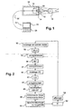
- the device according to the invention which is shown diagrammatically in FIG. 1, essentially comprises color video image acquisition means which consist of a matrix assembly 10 of photo-detectors, such as photodiodes or CCD photodetectors. and an imaging lens 12 on the set of photodetectors, as well as a source 14 of ultraviolet light for illuminating an object 16; such as a tooth in the mouth, located in front of the lens 12.
- color video image acquisition means consist of a matrix assembly 10 of photo-detectors, such as photodiodes or CCD photodetectors. and an imaging lens 12 on the set of photodetectors, as well as a source 14 of ultraviolet light for illuminating an object 16; such as a tooth in the mouth, located in front of the lens 12.
- the set 10 of photodetectors and the objective 12 are those of a color video camera of the "webcam" type, comprising, for example, a matrix of 320 ⁇ 240 pixels. a size of 1 ⁇ 4 inch (4 mm diagonally) and a focal length lens of 5 mm, which is available on the market at a relatively very low price.
- the ultraviolet light source is advantageously a light emitting diode emitting in a narrow band of wavelengths centered on about 370 nm.
- the camera 10, 12 and the source 14 of ultraviolet light are mounted inside a casing 18, for example cylindrical, having small dimensions, of the endoscope type, for example, which is easy to manipulate with one hand or which is variant, rotatably mounted on an articulated arm suspension or support.
- a flexible cable 20 connects the components 10, 14 housed in the housing 18 to a control apparatus 22 comprising information processing means, a display screen 24 and a control keyboard 26, as well as means for controlling the information. power supply of the entire device according to the invention.
- a light source 28 of any suitable type may also be housed in the housing 18 for illuminating the object 16 in visible light, preferably in white light.
- This device is used as follows:
- the housing 18 is positioned correctly with respect to the object 16, so as to be able to illuminate this object in ultraviolet light and possibly in visible light and to form a sharp image of this object on the set 10 of photodetectors. from the camera.
- the first step of the method according to the invention comprises, if necessary, the illumination 30 of the object 16 in visible light by means of the source 28, the taking 32 of a video image in color or in gray levels of the object 16, this image being a reference image in visible light IRLV, the recording 34 of this image in a memory of the apparatus 22, and the extinction of the source 28 of visible light.
- the next step of the method comprises taking a color image 36 of the illuminated object 16 in ambient light, to obtain a background noise image IBF, and recording 38 of this image in the memory of the camera. 22.
- the next step of the method comprises illuminating the object 16 in ultraviolet light by means of the source 14, taking a color video image of the object 12, this image being an image of ILB raw luminescence, the recording 44 of this image in the memory of the apparatus 22, and the extinction of the source 14 of ultraviolet light.
- the illumination in ultraviolet light of the object 16 is carried out by pulses of a duration corresponding to the exposure time of the CCD camera, each pulse causing fluorescence of the mineral part of the tooth and the lighting pulses being separated from each other by a time interval adapted to the acquisition sequences of the empty frames.
- the image of decay IC in false colors and the image of the tooth illuminated in visible light or in ambient light are simultaneously displayed on the screen 24. This makes it easy to pinpoint areas of decay on the examined tooth.
- control device restarts an acquisition and measurement cycle at the beginning, that is to say in step 30.
- Visible light illumination of the object being examined is only of interest if the video image of this object in ambient light is not good enough.
- the sensitivity of the photo-detectors of the video camera makes it possible to dispense with the illumination of the object in visible light by means of the source 28.
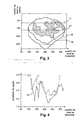
- FIG. 3 diagrammatically represents a decay image IC which is displayed in false colors, for example in red or blue, possibly on an image of a tooth illuminated with visible light IRLV or with ambient light IBF, the abscissa designating the numbers of the pixels in the horizontal rows of the set of photo-detectors of the camera, the ordinates designating the numbers of the pixels in the vertical columns of the photodetectors of this matrix set.
- FIG. 4 represents, for two measurement lines L1 and L2 of the image of FIG. 3, the variations of the ratio ILb / ILr as a function of the numbers of the pixels in the aforementioned horizontal rows.
- the color video sensor 10 of the device according to the invention may be a CCD-type matrix sensor or a photodiode array sensor, or a CMOS-type matrix sensor, or a color vidicon, or any other matrix device of FIG. acquisition of color image or color video sequence.
- the image forming means on this video sensor may be formed of a lens, lenses, mirrors, fiber optic image guides, etc., and in general any means for forming a image of an object 16 on the video sensor 10.
- the ultraviolet light source 14 may be a light emitting diode as already indicated, another semiconductor component, a heat source, an electric discharge lamp, a laser, etc., producing ultraviolet light in the light source. a wavelength band of about 300 to 370 nm for exciting the luminescence of the mineral part of the tooth 16.
- the light emitted by this source is not subject to any criterion of monochromaticity, coherence or state of polarization.
- this light source may be associated with optical collimation, transmission and / or power attenuation elements of the emitted light beam.
- the source 28 of visible light may be a light-emitting diode, another semiconductor component, a heat source, an electric discharge lamp, a laser, etc ..., and in general any means for generating a light visible, preferably white for the illumination of the object 16.
- This light source 28 may be associated with means for collimating, transmitting and / or attenuating the power of the emitted light beam.
- These light sources 14, 28 may be single or multiple point sources, single or multiple, and are assembled on the housing 18 at one end thereof or are remote, the light being transmitted by optical fibers for example.
Abstract
Description
L'invention concerne un procédé et un dispositif d'acquisition et de traitement d'images d'un objet, tel qu'une dent en bouche, éclairé en lumière ultraviolette.The invention relates to a method and a device for acquiring and processing images of an object, such as a tooth in the mouth, illuminated with ultraviolet light.
On connaît par le document WO-A-02/096281 un procédé de détection précoce de caries dentaires, qui consiste à éclairer une dent en bouche avec une lumière ultraviolette ayant une longueur d'onde comprise entre 300 et 370 nm environ pour exciter une émission de fluorescence par la partie minérale de la dent, à prendre des images vidéo de la dent dans deux bandes de longueurs d'ondes de haute énergie et de basse énergie respectivement du spectre d'émission, à mesurer l'intensité spectrale de la fluorescence émise dans ces deux bandes en chaque point de l'image de la dent, à faire les rapports des intensités mesurées dans les deux bandes en chaque point de l'image et à comparer ces rapports à une valeur prédéterminée.Document WO-A-02/096281 discloses a method for the early detection of dental caries, which consists in illuminating a tooth in the mouth with ultraviolet light having a wavelength of between approximately 300 and 370 nm to excite an emission of fluorescence by the mineral part of the tooth, to take video images of the tooth in two bands of high energy and low energy wavelengths respectively of the emission spectrum, to measure the spectral intensity of the fluorescence emitted in these two bands at each point of the image of the tooth, to make the ratios of the intensities measured in the two bands at each point of the image and to compare these ratios to a predetermined value.
Le rapport des intensités mesurées dans une bande de longueurs d'ondes comprises entre la longueur d'onde d'excitation et 600 nm environ et dans une bande de longueurs d'ondes comprises entre 550 et 800 nm environ, indique la présence d'une carie quand il est inférieur à une valeur prédéterminée qui dépend des sensibilités des photo-détecteurs des moyens vidéo de prise d'image dans ces deux bandes de longueurs d'ondes.The ratio of the intensities measured in a wavelength band between the excitation wavelength and approximately 600 nm and in a wavelength band of between approximately 550 and 800 nm, indicates the presence of a decay when it is less than a predetermined value which depends on the sensitivities of the photodetectors of the video-taking means in these two wavelength bands.
Le dispositif utilisé pour l'exécution de ce procédé comprend un laser et des filtres pour l'éclairage de la dent par des impulsions successives de lumière ultraviolette et de lumière visible, et en ce qui concerne les moyens de prise d'image, un dispositif de filtrage spectral comprenant deux filtres, dont l'un transmet les signaux de la bande de longueurs d'onde de haute énergie et l'autre les signaux de la bande de longueurs d'onde de basse énergie, et une caméra vidéo qui reçoit successivement les signaux transmis dans la bande de haute énergie, les signaux transmis dans la bande de basse énergie et des signaux correspondant à l'image de la dent éclairée en lumière visible. Des moyens de traitement de l'information calculent les rapports précités en chaque point de l'image de la dent à partir des signaux de sortie de la caméra et affichent sur un écran une image de fluorescence et une image en lumière visible de la dent, ce qui permet de localiser avec précision les caries éventuelles sur l'image de la dent.The device used for carrying out this method comprises a laser and filters for illuminating the tooth by successive pulses of ultraviolet light and visible light, and with regard to the image pickup means, a device spectral filtering device comprising two filters, one of which transmits the signals of the high energy wavelength band and the other the signals of the low energy wavelength band, and a video camera which receives successively the signals transmitted in the high energy band, the signals transmitted in the low energy band and signals corresponding to the image of the tooth illuminated in visible light. Information processing means calculates the aforementioned ratios at each point of the tooth image from the output signals of the camera and displays on a screen a fluorescence image and a visible light image of the tooth, This makes it possible to precisely locate any caries on the image of the tooth.
Ce dispositif connu fonctionne de façon satisfaisante mais est relativement coûteux. Il est aussi relativement peu rapide, puisqu'il faut interposer successivement des filtres devant la caméra pour acquérir les images de fluorescence dans les deux bandes de longueurs d'ondes et les images de la dent en lumière visible.This known device works satisfactorily but is relatively expensive. It is also relatively slow, since it is necessary to successively interpose filters in front of the camera to acquire the fluorescence images in the two wavelength bands and the images of the tooth in visible light.
La présente invention a notamment pour but de pallier ces inconvénients.The present invention is intended to overcome these disadvantages.
Elle a pour objet un procédé et un dispositif du type précité, qui sont applicables notamment à la détection précoce des caries dentaires et de façon plus générale à la détection d'altérations et de variations des propriétés des surfaces et des volumes accessibles optiquement d'objets quelconques, ce procédé et ce dispositif utilisant des matériels et des composants simples et bon marché.It relates to a method and a device of the aforementioned type, which are applicable in particular to the early detection of dental caries and more generally to the detection of alterations and variations in the properties of surfaces and optically accessible volumes of objects. This method and device utilizes simple and inexpensive hardware and components.
Elle a également pour objet un procédé et un dispositif du type précité, qui permettent une acquisition et un traitement plus rapides et plus précis des images de l'objet examiné.It also relates to a method and a device of the aforementioned type, which allow a faster and more accurate acquisition and processing of the images of the examined object.
Elle propose, à cet effet, un procédé d'acquisition et de traitement d'image d'un objet tel par exemple qu'une dent en bouche, consistant à éclairer l'objet en lumière ultraviolette, à prendre avec des moyens vidéo des images de la partie éclairée de l'objet, à mesurer en chaque point de ces images l'intensité spectrale de la luminescence émise par l'objet dans deux bandes de longueurs d'ondes de haute et de basse énergie respectivement, à faire le rapport de ces mesures en chaque point de l'image de l'objet et à comparer ce rapport à une valeur prédéterminée, caractérisé en ce qu'il consiste :
- à prendre au moins une image vidéo en couleurs de ladite partie de l'objet éclairée en lumière ambiante,
- à prendre au moins une image vidéo en couleurs de la luminescence produite par ladite partie de l'objet en réponse à l'éclairage de cette partie en lumière ultraviolette,
- à soustraire l'image vidéo en lumière ambiante de l'image vidéo de luminescence, en chaque point de cette image de luminescence, pour obtenir une image pure,
- à extraire les composantes spectrales de l'image pure dans lesdites bandes de haute et de basse énergie,
- à faire les rapports de ces composantes en chaque point d'image et à comparer ces rapports à une valeur prédéterminée.
- taking at least one color video image of said portion of the illuminated object in ambient light,
- taking at least one color video image of the luminescence produced by said part of the object in response to illumination of this portion in ultraviolet light,
- subtracting the video image in ambient light from the luminescence video image, at each point of this luminescence image, to obtain a pure image,
- extracting the spectral components of the pure image in said high and low energy bands,
- to make the ratios of these components in each image point and to compare these ratios to a predetermined value.
Il suffit donc, dans le procédé selon l'invention, d'un éclairage de l'objet en lumière ambiante et d'un éclairage de l'objet en lumière ultraviolette pour obtenir au moyen d'une caméra vidéo couleur les informations nécessaires au calcul des rapports précités, et l'on n'a plus besoin d'utiliser des filtres que l'on commute devant la caméra vidéo, puisque l'on peut disposer directement des composantes des images vidéo dans les bandes de longueurs d'ondes de haute et de basse énergie.It is therefore sufficient, in the method according to the invention, illumination of the object in ambient light and illumination of the object in ultraviolet light to obtain by means of a color video camera the information necessary for the calculation. reports, and there is no need to use filters that are switched in front of the video camera, since the components of the video images can be directly arranged in the high wavelength bands. and low energy.
Avantageusement, le procédé selon l'invention consiste à utiliser une caméra vidéo couleur du type rouge - vert - bleu pour prendre les images de l'objet et à extraire les composantes rouges et bleues des images vidéo pour calculer les rapports précités.Advantageously, the method according to the invention consists in using a color video camera of the red-green-blue type to take the images of the object and to extract the red and blue components of the video images to calculate the aforementioned reports.
L'invention propose également un dispositif pour l'exécution de ce procédé, comprenant une source de lumière ultraviolette pour l'éclairage de l'objet, des moyens vidéo de prise d'images d'une partie éclairée de l'objet et des moyens de traitement de l'information recevant les signaux de sortie des moyens vidéo, caractérisé en ce que les moyens vidéo comprennent une caméra vidéo couleur et en ce que les moyens de traitement de l'information sont prévus pour soustraire, point par point, une image de la partie de l'objet éclairée en lumière ambiante d'une image de la partie de l'objet éclairée en lumière ultraviolette, afin d'obtenir une image pure, extraire les composantes de cette image pure dans deux bandes de longueurs d'ondes de haute énergie et de basse énergie respectivement, faire les rapports point par point de ces deux composantes et les comparer à une valeur prédéterminée.The invention also proposes a device for executing this method, comprising a source of ultraviolet light for illuminating the object, video imaging means of an illuminated part of the object and means for processing the information receiving the output signals from the video means, characterized in that the video means comprise a color video camera and in that the information processing means are provided for subtracting, point by point, an image of the part of the object illuminated in ambient light with an image of the part of the object illuminated with ultraviolet light, in order to obtain a pure image, extracting the components of this pure image in two bands of high wavelengths energy and low energy respectively, make the point-by-point ratios of these two components and compare them to a predetermined value.
Avantageusement, la caméra vidéo couleur utilisée est une caméra matricielle CCD du type "webcam" ayant un prix relativement très bas (typiquement de moins de 100 euros).Advantageously, the color video camera used is a CCD camera type "webcam" with a relatively low price (typically less than 100 euros).
Selon d'autres caractéristiques de l'invention, ce dispositif comprend des moyens d'affichage d'un résultat formé par les points d'image dont les rapports sont inférieurs (ou supérieurs, respectivement) à la valeur prédéterminée.According to other characteristics of the invention, this device comprises means for displaying a result formed by the image points whose ratios are lower (or higher, respectively) than the predetermined value.
La source de lumière ultraviolette utilisée dans ce dispositif est de préférence une diode électroluminescente émettant une lumière ultraviolette dans une bande étroite de longueurs d'onde centrée sur 370 nm environ par exemple.The ultraviolet light source used in this device is preferably a light emitting diode emitting ultraviolet light in a narrow band of wavelengths centered on about 370 nm for example.
Un dispositif comprenant ces moyens a un prix de revient très faible et est cependant d'une fiabilité et d'une précision surprenantes.A device comprising these means has a very low cost and is however of surprising reliability and accuracy.
Dans un mode de réalisation préféré de l'invention, la caméra vidéo couleur, comprenant un objectif de formation d'images, et la source de lumière ultraviolette sont logées dans un boîtier de faibles dimensions et sont reliées par un câble souple aux moyens de traitement de l'information.In a preferred embodiment of the invention, the color video camera, comprising an imaging lens, and the ultraviolet light source are housed in a small package and are connected by a flexible cable to the processing means. some information.
Ce boîtier est manipulable comme un endoscope et permet facilement des prises d'images sur les dents en bouche.This case is manipulable as an endoscope and easily allows images to be taken on the teeth in the mouth.
Si nécessaire, il peut contenir également une source de lumière visible pour l'éclairage de l'objet, lorsque l'éclairage ambiant n'est pas suffisant ou que la sensibilité des photo-détecteurs de la caméra est un peu faible.If necessary, it can also contain a visible light source for the illumination of the object, when the ambient lighting is not sufficient or that the sensitivity of the photo-detectors of the camera is a little weak.
De façon générale, l'invention est applicable à la détection d'altérations et de variations des propriétés des surfaces, des interfaces et des volumes accessibles optiquement d'un objet quelconque dans des domaines divers tels que l'oncologie, la biologie, la géologie, l'écologie, le contrôle industriel, etc.In general, the invention is applicable to the detection of alterations and variations in the properties of surfaces, interfaces and Optically accessible volumes of any object in various fields such as oncology, biology, geology, ecology, industrial control, etc.
L'invention sera mieux comprise, et d'autres caractéristiques, détails et avantages de celle-ci apparaîtront plus clairement à la lecture de la description qui suit, faite à titre d'exemple en référence aux dessins annexés dans lesquels :
- La figure 1 est une vue schématique du dispositif selon l'invention;
- La figure 2 est un organigramme des principales étapes du procédé selon l'invention;
- La figure 3 représente schématiquement une image de fluorescence d'une dent en bouche ;
- La figure 4 est un graphe représentant les variations des rapports de luminescence dans les bandes spectrales de haute et de basse énergie, le long de deux lignes de l'image de la figure 3.
- Figure 1 is a schematic view of the device according to the invention;
- Figure 2 is a flow chart of the main steps of the method according to the invention;
- Figure 3 schematically shows a fluorescence image of a tooth in the mouth;
- FIG. 4 is a graph showing the variations of the luminescence ratios in the high and low energy spectral bands, along two lines of the image of FIG.
Le dispositif selon l'invention qui est représenté schématiquement en figure 1, comprend essentiellement des moyens de prise d'image vidéo couleur qui sont constitués d'un ensemble matriciel 10 de photo-détecteurs, tels que des photodiodes ou des photo-détecteurs CCD, et d'un objectif 12 de formation d'image sur l'ensemble 10 de photo-détecteurs, ainsi qu'une source 14 de lumière ultraviolette pour l'éclairage d'un objet 16; tel par exemple qu'une dent en bouche, situé devant l'objectif 12.The device according to the invention, which is shown diagrammatically in FIG. 1, essentially comprises color video image acquisition means which consist of a
Dans un mode de réalisation préféré de l'invention, l'ensemble 10 de photo-détecteurs et l'objectif 12 sont ceux d'une caméra vidéo couleur du type "webcam", comprenant par exemple une matrice de 320 x 240 pixels d'une taille de ¼ de pouce (4 mm en diagonale) et un objectif de longueur focale de 5 mm, qui est disponible sur le marché à un prix relativement très faible.In a preferred embodiment of the invention, the
La source de lumière ultraviolette est avantageusement une diode électroluminescente émettant dans une bande étroite de longueurs d'onde centrée sur 370 nm environ.The ultraviolet light source is advantageously a light emitting diode emitting in a narrow band of wavelengths centered on about 370 nm.
La caméra 10, 12 et la source 14 de lumière ultraviolette sont montées à l'intérieur d'un boîtier 18 par exemple cylindrique, ayant de faibles dimensions, du type endoscope par exemple qui est facilement manipulable d'une main ou qui est, en variante, monté de façon orientable sur un bras articulé de suspension ou de support.The
Un câble souple 20 relie les composants 10, 14 logés dans le boîtier 18 à un appareil de commande 22 comprenant des moyens de traitement de l'information, un écran d'affichage 24 et un clavier de commande 26, ainsi que des moyens d'alimentation électrique de l'ensemble du dispositif selon l'invention.A
Une source lumineuse 28 d'un type quelconque approprié peut également être logée dans le boîtier 18 pour l'éclairage de l'objet 16 en lumière visible, de préférence en lumière blanche.A
Ce dispositif est utilisé de la façon suivante:This device is used as follows:
On positionne de façon correcte le boîtier 18 par rapport à l'objet 16, de façon à pouvoir éclairer cet objet en lumière ultraviolette et éventuellement-en lumière visible et à former une image nette de cet objet sur l'ensemble 10 de photo-détecteurs de la caméra.The
La première étape du procédé selon l'invention, comprend, si nécessaire, l'éclairage 30 de l'objet 16 en lumière visible au moyen de la source 28, la prise 32 d'une image vidéo en couleurs ou en niveaux de gris de l'objet 16, cette image étant une image de référence en lumière visible IRLV, l'enregistrement 34 de cette image dans une mémoire de l'appareil 22, et l'extinction de la source 28 de lumière visible.The first step of the method according to the invention comprises, if necessary, the
L'étape suivante du procédé comprend une prise 36 d'image en couleurs de l'objet 16 éclairé en lumière ambiante, pour obtenir une image de bruit de fond IBF, et l'enregistrement 38 de cette image dans la mémoire de l'appareil 22.The next step of the method comprises taking a
L'étape suivante du procédé comprend l'éclairage 40 de l'objet 16 en lumière ultraviolette au moyen de la source 14, la prise 40 d'une image vidéo en couleurs de l'objet 12, cette image étant une image de luminescence brute ILB, l'enregistrement 44 de cette image dans la mémoire de l'appareil 22, et l'extinction de la source 14 de lumière ultraviolette.The next step of the method comprises illuminating the
L'éclairage en lumière ultraviolette de l'objet 16 est réalisé par des impulsions d'une durée correspondant au temps d'exposition de la caméra CCD, chaque impulsion provoquant une fluorescence de la partie minérale de la dent et les impulsions d'éclairage étant séparées l'une de l'autre par un intervalle de temps adapté aux séquences d'acquisition des trames vides.The illumination in ultraviolet light of the
Pour améliorer la précision et réduire le bruit, on peut accumuler plusieurs trames vidéo correspondant aux images de référence en lumière visible IRLV, de bruit de fond IBF et de luminescence brute ILB et les moyenner, le nombre de trames accumulées étant le même pour chaque type d'image.To improve the accuracy and to reduce the noise, it is possible to accumulate several video frames corresponding to the reference images in visible light IRLV, background noise IBF and raw luminescence ILB and to average them, the number of accumulated frames being the same for each type. image.
Les étapes suivantes du procédé comprennent:
- En 46, une soustraction point par point (pixel par pixel ou groupe de pixels par groupe de pixels) de l'image en lumière ambiante IBF de l'image en éclairage ultraviolet ILB pour obtenir une image IL de luminescence pure,
- En 48, l'extraction des composantes rouge ILr et bleue ILb de l'image IL de luminescence pure,
- En 50, le calcul point par point des rapports ILb/ILr (ou ILr/ILb),
- En 52, la comparaison de ces rapports à une valeur prédéterminée,
- En 54, l'affichage d'une image de carie IC formée des points pour lesquels les rapports précités ILb/ILr sont inférieurs à une valeur prédéterminée (ou des points pour lesquels les rapports ILr/ILb sont supérieurs à une valeur prédéterminée).
- At 46, a point-by-point subtraction (pixel by pixel or group of pixels by pixel group) of the ambient light image IBF of the ultraviolet illumination image ILB to obtain an IL image of pure luminescence,
- At 48, the extraction of the red ILr and blue ILb components of the IL image of pure luminescence,
- In 50, the point-by-point calculation of the ILb / ILr (or ILr / ILb) ratios,
- In 52, the comparison of these ratios to a predetermined value,
- At 54, displaying a decay image IC formed of points for which the aforementioned ILb / ILr ratios are less than a predetermined value (or points for which the ILr / ILb ratios are greater than a predetermined value).
Avantageusement, on affiche simultanément sur l'écran 24 l'image de carie IC en fausses couleurs et l'image de la dent éclairée en lumière visible ou en lumière ambiante. Cela permet de repérer facilement avec précision les zones de carie sur la dent examinée.Advantageously, the image of decay IC in false colors and the image of the tooth illuminated in visible light or in ambient light are simultaneously displayed on the
Ensuite, l'appareil de commande redémarre un cycle d'acquisition et de mesure au début, c'est-à-dire à l'étape 30.Then, the control device restarts an acquisition and measurement cycle at the beginning, that is to say in
L'éclairage en lumière visible de l'objet examiné ne présente un intérêt que si l'image vidéo de cet objet en lumière ambiante n'est pas suffisamment bonne.Visible light illumination of the object being examined is only of interest if the video image of this object in ambient light is not good enough.
Dans la plupart des cas, la-sensibilité des photo-détecteurs de la caméra vidéo permet de se dispenser de l'éclairage de l'objet en lumière visible au moyen de la source 28.In most cases, the sensitivity of the photo-detectors of the video camera makes it possible to dispense with the illumination of the object in visible light by means of the
La figure 3 représente schématiquement une image de carie IC qui est affichée en fausses couleurs, par exemple en rouge ou en bleu, éventuellement sur une image d'une dent éclairée en lumière visible IRLV ou en lumière ambiante IBF, les abscisses désignant les numéros des pixels dans les rangées horizontales de l'ensemble de photo-détecteurs de la caméra, les ordonnées désignant les numéros des pixels dans les colonnes verticales des photo-détecteurs de cet ensemble matriciel.FIG. 3 diagrammatically represents a decay image IC which is displayed in false colors, for example in red or blue, possibly on an image of a tooth illuminated with visible light IRLV or with ambient light IBF, the abscissa designating the numbers of the pixels in the horizontal rows of the set of photo-detectors of the camera, the ordinates designating the numbers of the pixels in the vertical columns of the photodetectors of this matrix set.
La figure 4 représente, pour deux lignes de mesures L1 et L2 de l'image de la figure 3, les variations du rapport ILb/ILr en fonction des numéros des pixels dans les rangées horizontales précitées.FIG. 4 represents, for two measurement lines L1 and L2 of the image of FIG. 3, the variations of the ratio ILb / ILr as a function of the numbers of the pixels in the aforementioned horizontal rows.
Les valeurs de ce rapport qui sont voisines de 2,5 correspondent à un émail sain et celles qui sont inférieures à 2 correspondent à une carie.Values in this ratio that are close to 2.5 are healthy enamel, and values below 2 are caries.
Un certain nombre de variantes peuvent être apportées au dispositif selon l'invention qui a été décrit et représenté, sans sortir du cadre de l'invention défini par les revendications qui suivent.A number of variants can be made to the device according to the invention which has been described and shown without departing from the scope of the invention defined by the following claims.
Par exemple, le capteur vidéo couleur 10 du dispositif selon l'invention peut être un capteur matriciel du type CCD ou un capteur matriciel à photodiodes, ou un capteur matriciel du type CMOS, ou encore un vidicon couleur, ou tout autre dispositif matriciel d'acquisition d'image couleur ou de séquence vidéo en couleur.For example, the
Les moyens de formation d'image sur ce capteur vidéo peuvent être formés d'un objectif, de lentilles, de miroirs, de guides d'image à fibres optiques, etc..., et en général de tout moyen permettant de former une image d'un objet 16 sur le capteur vidéo 10.The image forming means on this video sensor may be formed of a lens, lenses, mirrors, fiber optic image guides, etc., and in general any means for forming a image of an
La source 14 d'éclairage en lumière ultraviolette peut être une diode électroluminescente comme déjà indiqué, un autre composant semi-conducteur, une source thermique, une lampe à décharge électrique, un laser, etc...., produisant une lumière ultraviolette dans la bande de longueurs d'onde de 300 à 370 nm environ permettant d'exciter la luminescence de la partie minérale de la dent 16.The ultraviolet
La lumière émise par cette source n'est soumise à aucun critère de monochromaticité, de cohérence ou d'état de polarisation. Bien entendu, cette source de lumière peut être associée à des éléments optiques de collimation, de transmission et / ou d'atténuation de puissance du faisceau lumineux émis.The light emitted by this source is not subject to any criterion of monochromaticity, coherence or state of polarization. Of course, this light source may be associated with optical collimation, transmission and / or power attenuation elements of the emitted light beam.
De même, la source 28 de lumière visible peut être une diode électroluminescente, un autre composant semi-conducteur, une source thermique, une lampe à décharge électrique, un laser, etc..., et en général tout moyen permettant de générer une lumière visible, de préférence blanche pour l'éclairage de l'objet 16.Similarly, the
Cette source de lumière 28 peut être associée à des moyens de collimation, de transmission et / ou d'atténuation de puissance du faisceau lumineux émis.This
Ces sources -lumineuses 14, 28 peuvent être des sources ponctuelles ou étendues, uniques ou multiples, et sont assemblées sur le boîtier 18 à une extrémité de celui-ci ou sont éloignées, la lumière étant transmise par des fibres optiques par exemple.These
Claims (13)
- A method of acquiring and processing images of an article, such as a tooth in the mouth, consisting in illuminating the article (16) in ultraviolet light, in using video means (10, 12) to take images of the illuminated portion of the article, in measuring at each point of said images the spectral intensity of the luminescence emitted by the article in two wavelength bands respectively at high energy and at low energy, in taking the ratio of said measurements at each point of the image of the article, and in comparing said ratios with a predetermined value, consisting:· in taking at least one color video image of said portion of the article (16) illuminated in ambient light,· in taking at least one color video image of the luminescence produced by said portion of the article (16) in response to being illuminated in ultraviolet light, characterized in that it further consists:· in subtracting the ambient light video image from the luminescence video image at each point of the luminescence image in order to obtain a pure image,· in extracting the spectral components of the pure image in said high-energy and low-energy wavelength bands, and· in taking the ratios of said components at each point of the image and in comparing said ratios with a predetermined value.
- A method according to claim 1, characterized in that it consists in displaying on a screen a result made up of image points for which the above-mentioned ratio is less than (or respectively greater than) the above-mentioned predetermined value.
- A method according to claim 2, characterized in that it consists in displaying said result simultaneously with said color video image of the portion of the article as illuminated in ambient light or a video image of said portion of the article as illuminated in visible light.
- A method according to claim 3, characterized in that it consists in displaying the above-mentioned result in false colors superimposed on the video image of the article in ambient light or in visible light.
- A method according to any preceding claim, characterized in that it consists in taking images of the article by means of a red-green-blue type matrix video camera, and in using the red and blue components of said image to calculate the above-mentioned ratios.
- A method according to any preceding claim, characterized in that it consists in taking a plurality of video images of the portion of the article illuminated in ambient light and in ultraviolet light, in calculating the averages of said images, and then in using said averages for calculating the above-mentioned ratios.
- Apparatus for performing the method described in any preceding claim, comprising an ultraviolet light source (14) for illuminating an article (16), video means (10, 12) for taking an image of the illuminated portion of the article, and data processor means (22) receiving the output signals from the video means, characterized in that the video means comprise a color video camera (10, 12), and in that the data processor means are designed to subtract, point by point, an image of the portion of the article illuminated in ambient light from an image of the portion of the article illuminated in ultraviolet light so as to obtain a pure image, to extract the components from said pure image in the two wavelength bands respectively at high energy and at low energy, to take the ratios point by point of these two components, and to compare them with a predetermined value.
- Apparatus according to claim 7, characterized in that it comprises means (24) for displaying the results formed by the image points for which the ratios are less than (or respectively greater than) the predetermined value.
- Apparatus according to claim 7 or claim 8, characterized in that it includes means (24) for displaying an ambient light image or a visible light image of said portion of the article and the result formed by the points of the image having ratios that are less than (or respectively greater than) the predetermined value.
- Apparatus according to any one of claims 7 to 9, characterized in that the color video camera (10, 12) is a CCD, CMOS, or photodiode matrix camera, or a color vidicon.
- Apparatus according to any one of claims 7 to 10, characterized in that the ultraviolet light source (14) is an LED emitting in a wavelength band lying in the range about 300 nm to about 370 nm.
- Apparatus according to any one of claims 7 to 11, characterized in that both the ultraviolet light source (14) and the color video camera including an image-forming lens (12) are housed in a housing (18) of small dimensions, and are connected by a flexible cable (20) to the data processor means (22).
- Apparatus according to any one of claims 7 to 12, characterized in that the housing (18) also contains a source (28) of visible light for illuminating the article (16).
Applications Claiming Priority (2)
| Application Number | Priority Date | Filing Date | Title |
|---|---|---|---|
| FR0307294A FR2856546B1 (en) | 2003-06-17 | 2003-06-17 | METHOD AND DEVICE FOR ACQUIRING AND PROCESSING IMAGES OF AN OBJECT SUCH AS A TOOTH |
| PCT/FR2004/001411 WO2005002429A1 (en) | 2003-06-17 | 2004-06-07 | Method and device for recording and processing images of an object such as a tooth |
Publications (2)
| Publication Number | Publication Date |
|---|---|
| EP1633243A1 EP1633243A1 (en) | 2006-03-15 |
| EP1633243B1 true EP1633243B1 (en) | 2007-04-04 |
Family
ID=33484509
Family Applications (1)
| Application Number | Title | Priority Date | Filing Date |
|---|---|---|---|
| EP04767277A Not-in-force EP1633243B1 (en) | 2003-06-17 | 2004-06-07 | Method and device for recording and processing images of an object such as a tooth |
Country Status (8)
| Country | Link |
|---|---|
| US (1) | US20060239526A1 (en) |
| EP (1) | EP1633243B1 (en) |
| JP (1) | JP2006527615A (en) |
| AT (1) | ATE358438T1 (en) |
| CA (1) | CA2529201A1 (en) |
| DE (1) | DE602004005708D1 (en) |
| FR (1) | FR2856546B1 (en) |
| WO (1) | WO2005002429A1 (en) |
Families Citing this family (21)
| Publication number | Priority date | Publication date | Assignee | Title |
|---|---|---|---|---|
| US7596253B2 (en) | 2005-10-31 | 2009-09-29 | Carestream Health, Inc. | Method and apparatus for detection of caries |
| GB2439771A (en) * | 2006-07-05 | 2008-01-09 | Qinetiq Ltd | Clock controlled gating in quantum cryptography apparatus |
| US7668355B2 (en) * | 2006-08-31 | 2010-02-23 | Carestream Health, Inc. | Method for detection of caries |
| US8224045B2 (en) * | 2007-01-17 | 2012-07-17 | Carestream Health, Inc. | System for early detection of dental caries |
| US7929151B2 (en) * | 2008-01-11 | 2011-04-19 | Carestream Health, Inc. | Intra-oral camera for diagnostic and cosmetic imaging |
| US8866894B2 (en) | 2008-01-22 | 2014-10-21 | Carestream Health, Inc. | Method for real-time visualization of caries condition |
| US8184147B2 (en) * | 2008-07-24 | 2012-05-22 | Kevin Crucs | Apparatus and methods for full-mouth intraoral image acquisition |
| US8768016B2 (en) * | 2009-06-19 | 2014-07-01 | Carestream Health, Inc. | Method for quantifying caries |
| US8687859B2 (en) | 2009-10-14 | 2014-04-01 | Carestream Health, Inc. | Method for identifying a tooth region |
| US8908936B2 (en) * | 2009-10-14 | 2014-12-09 | Carestream Health, Inc. | Method for extracting a carious lesion area |
| US9235901B2 (en) * | 2009-10-14 | 2016-01-12 | Carestream Health, Inc. | Method for locating an interproximal tooth region |
| US8571281B2 (en) * | 2010-07-13 | 2013-10-29 | Carestream Health, Inc. | Dental shade mapping |
| US20130016262A1 (en) * | 2011-07-14 | 2013-01-17 | Majewicz Peter I | Imager exposure control |
| US9486141B2 (en) | 2011-08-09 | 2016-11-08 | Carestream Health, Inc. | Identification of dental caries in live video images |
| CN103181832A (en) * | 2011-12-27 | 2013-07-03 | 上海市口腔病防治院 | Standard light source lamp box for dental medical treatment |
| US9510757B2 (en) * | 2014-05-07 | 2016-12-06 | Align Technology, Inc. | Identification of areas of interest during intraoral scans |
| TWI539935B (en) * | 2014-05-27 | 2016-07-01 | Metal Ind Res & Dev Ct | Method for establishing dual - wavelength tooth images |
| DK3578131T3 (en) | 2016-07-27 | 2020-12-21 | Align Technology Inc | Intraoral scanner with dental diagnostic features |
| US10507087B2 (en) | 2016-07-27 | 2019-12-17 | Align Technology, Inc. | Methods and apparatuses for forming a three-dimensional volumetric model of a subject's teeth |
| CN106473693A (en) * | 2016-10-20 | 2017-03-08 | 成都迅德科技有限公司 | A kind of mouth lamp |
| AU2019212649A1 (en) * | 2018-01-26 | 2020-07-02 | Align Technology, Inc. | Diagnostic intraoral scanning and tracking |
Family Cites Families (10)
| Publication number | Priority date | Publication date | Assignee | Title |
|---|---|---|---|---|
| USRE31815E (en) * | 1979-08-20 | 1985-01-29 | Philips Medical Systems, Inc. | Method and apparatus for detecting the presence of caries in teeth using visible luminescence |
| DE4200741C2 (en) * | 1992-01-14 | 2000-06-15 | Kaltenbach & Voigt | Device for the detection of caries on teeth |
| DE9317984U1 (en) * | 1993-11-24 | 1995-03-23 | Kaltenbach & Voigt | Device for detecting caries |
| US6293911B1 (en) * | 1996-11-20 | 2001-09-25 | Olympus Optical Co., Ltd. | Fluorescent endoscope system enabling simultaneous normal light observation and fluorescence observation in infrared spectrum |
| US6571118B1 (en) * | 1998-05-04 | 2003-05-27 | Board Of Regents, The University Of Texas System | Combined fluorescence and reflectance spectroscopy |
| US6525819B1 (en) * | 1998-09-02 | 2003-02-25 | Pocketspec Technologies Inc. | Colorimeter for dental applications |
| DE60021417T2 (en) * | 1999-12-08 | 2006-05-24 | X-Rite, Inc., Grandville | Optical measuring device |
| US6925205B2 (en) * | 2000-08-07 | 2005-08-02 | Digital Colour Measurement Limited | Methods, systems and computer program products for color matching |
| FR2825260B1 (en) | 2001-06-01 | 2004-08-20 | Centre Nat Rech Scient | METHOD AND DEVICE FOR DETECTION OF DENTAL CARIES |
| DE10133451B4 (en) * | 2001-07-10 | 2012-01-26 | Ferton Holding S.A. | Device for detecting caries, plaque, concrements or bacterial infestation of teeth |
-
2003
- 2003-06-17 FR FR0307294A patent/FR2856546B1/en not_active Expired - Fee Related
-
2004
- 2004-06-07 DE DE602004005708T patent/DE602004005708D1/en active Active
- 2004-06-07 WO PCT/FR2004/001411 patent/WO2005002429A1/en active IP Right Grant
- 2004-06-07 CA CA002529201A patent/CA2529201A1/en not_active Abandoned
- 2004-06-07 AT AT04767277T patent/ATE358438T1/en not_active IP Right Cessation
- 2004-06-07 JP JP2006516264A patent/JP2006527615A/en not_active Withdrawn
- 2004-06-07 EP EP04767277A patent/EP1633243B1/en not_active Not-in-force
-
2005
- 2005-12-16 US US11/304,630 patent/US20060239526A1/en not_active Abandoned
Non-Patent Citations (1)
| Title |
|---|
| None * |
Also Published As
| Publication number | Publication date |
|---|---|
| CA2529201A1 (en) | 2005-01-13 |
| EP1633243A1 (en) | 2006-03-15 |
| US20060239526A1 (en) | 2006-10-26 |
| DE602004005708D1 (en) | 2007-05-16 |
| ATE358438T1 (en) | 2007-04-15 |
| FR2856546B1 (en) | 2005-11-04 |
| WO2005002429A1 (en) | 2005-01-13 |
| FR2856546A1 (en) | 2004-12-24 |
| JP2006527615A (en) | 2006-12-07 |
Similar Documents
| Publication | Publication Date | Title |
|---|---|---|
| EP1633243B1 (en) | Method and device for recording and processing images of an object such as a tooth | |
| JP6939000B2 (en) | Imaging device and imaging method | |
| EP2351518B1 (en) | Perioperative bi-spectral optical probe | |
| CN101426420B (en) | Optical detection of dental caries | |
| EP1392158A1 (en) | Method and device for the acquisition and treatment of dental images | |
| EP2071322B1 (en) | Analysesystem mit Hilfe der Fluoreszenz eines Felds in einer beleuchteten Zone | |
| FR2985023A1 (en) | SYSTEM FOR RECONSTRUCTING OPTICAL PROPERTIES OF A DIFFUSING MEDIUM, COMPRISING A PULSE RADIATION SOURCE AND AT LEAST TWO DETECTORS OF TWO DIFFERENT TYPES, AND ASSOCIATED RECONSTRUCTION METHOD | |
| FR2591470A1 (en) | METHOD AND DEVICE FOR DETERMINING THE COLOR, IN PARTICULAR A DENTAL PROSTHESIS | |
| EP0604276A1 (en) | Method and device for determining the colour of a transparent, diffusing and absorbing object, especially of a tooth | |
| EP0106721A2 (en) | System for the observation and automatic quantitative valuation of events detectable by fluorescence | |
| FR2891924A1 (en) | LUMINESCENCE IMAGING DEVICE AND METHOD | |
| FR3094857A1 (en) | Pulsed light imaging process | |
| FR3031035B1 (en) | IMAGING DEVICE AND IMAGING METHOD | |
| EP3833999B1 (en) | System for optical characterization of a zone of interest of an object | |
| EP2179270B1 (en) | Method and system for characterizing a pigmented biological tissue. | |
| EP3384254B1 (en) | Medical device for fibred bimodal optical spectroscopy | |
| EP3884656B1 (en) | Device and method for observing a scene comprising a target | |
| EP1429169A1 (en) | Optical microscope with modifiable lighting and method of operation thereof | |
| FR3051041A1 (en) | REMOVABLE ACCESSORY FOR TRANSFORMING INTO SPECTROMETER AN ELECTRONIC APPARATUS EQUIPPED WITH A PHOTOSENSITIVE MULTI-PIXEL SENSOR. | |
| EP0286490A1 (en) | Apparatus for ocular monitoring by means of infrared radiation reflected from the eyeball | |
| US20130070246A1 (en) | Optical detection apparatus | |
| FR2894666A1 (en) | SYSTEM FOR OPTICALLY MEASURING THE COLORIMETRY OF AN OBJECT |
Legal Events
| Date | Code | Title | Description |
|---|---|---|---|
| PUAI | Public reference made under article 153(3) epc to a published international application that has entered the european phase |
Free format text: ORIGINAL CODE: 0009012 |
|
| 17P | Request for examination filed |
Effective date: 20051207 |
|
| AK | Designated contracting states |
Kind code of ref document: A1 Designated state(s): AT BE BG CH CY CZ DE DK EE ES FI FR GB GR HU IE IT LI LU MC NL PL PT RO SE SI SK TR |
|
| DAX | Request for extension of the european patent (deleted) | ||
| GRAP | Despatch of communication of intention to grant a patent |
Free format text: ORIGINAL CODE: EPIDOSNIGR1 |
|
| GRAC | Information related to communication of intention to grant a patent modified |
Free format text: ORIGINAL CODE: EPIDOSCIGR1 |
|
| GRAS | Grant fee paid |
Free format text: ORIGINAL CODE: EPIDOSNIGR3 |
|
| GRAA | (expected) grant |
Free format text: ORIGINAL CODE: 0009210 |
|
| AK | Designated contracting states |
Kind code of ref document: B1 Designated state(s): AT BE BG CH CY CZ DE DK EE ES FI FR GB GR HU IE IT LI LU MC NL PL PT RO SE SI SK TR |
|
| PG25 | Lapsed in a contracting state [announced via postgrant information from national office to epo] |
Ref country code: SI Free format text: LAPSE BECAUSE OF FAILURE TO SUBMIT A TRANSLATION OF THE DESCRIPTION OR TO PAY THE FEE WITHIN THE PRESCRIBED TIME-LIMIT Effective date: 20070404 Ref country code: FI Free format text: LAPSE BECAUSE OF FAILURE TO SUBMIT A TRANSLATION OF THE DESCRIPTION OR TO PAY THE FEE WITHIN THE PRESCRIBED TIME-LIMIT Effective date: 20070404 |
|
| REG | Reference to a national code |
Ref country code: GB Ref legal event code: FG4D Free format text: NOT ENGLISH |
|
| REG | Reference to a national code |
Ref country code: CH Ref legal event code: EP |
|
| REF | Corresponds to: |
Ref document number: 602004005708 Country of ref document: DE Date of ref document: 20070516 Kind code of ref document: P |
|
| REG | Reference to a national code |
Ref country code: IE Ref legal event code: FG4D Free format text: LANGUAGE OF EP DOCUMENT: FRENCH |
|
| PG25 | Lapsed in a contracting state [announced via postgrant information from national office to epo] |
Ref country code: SE Free format text: LAPSE BECAUSE OF FAILURE TO SUBMIT A TRANSLATION OF THE DESCRIPTION OR TO PAY THE FEE WITHIN THE PRESCRIBED TIME-LIMIT Effective date: 20070704 |
|
| PG25 | Lapsed in a contracting state [announced via postgrant information from national office to epo] |
Ref country code: ES Free format text: LAPSE BECAUSE OF FAILURE TO SUBMIT A TRANSLATION OF THE DESCRIPTION OR TO PAY THE FEE WITHIN THE PRESCRIBED TIME-LIMIT Effective date: 20070715 |
|
| PG25 | Lapsed in a contracting state [announced via postgrant information from national office to epo] |
Ref country code: PT Free format text: LAPSE BECAUSE OF FAILURE TO SUBMIT A TRANSLATION OF THE DESCRIPTION OR TO PAY THE FEE WITHIN THE PRESCRIBED TIME-LIMIT Effective date: 20070904 |
|
| NLV1 | Nl: lapsed or annulled due to failure to fulfill the requirements of art. 29p and 29m of the patents act | ||
| GBV | Gb: ep patent (uk) treated as always having been void in accordance with gb section 77(7)/1977 [no translation filed] |
Effective date: 20070404 |
|
| PG25 | Lapsed in a contracting state [announced via postgrant information from national office to epo] |
Ref country code: AT Free format text: LAPSE BECAUSE OF FAILURE TO SUBMIT A TRANSLATION OF THE DESCRIPTION OR TO PAY THE FEE WITHIN THE PRESCRIBED TIME-LIMIT Effective date: 20070404 Ref country code: PL Free format text: LAPSE BECAUSE OF FAILURE TO SUBMIT A TRANSLATION OF THE DESCRIPTION OR TO PAY THE FEE WITHIN THE PRESCRIBED TIME-LIMIT Effective date: 20070404 |
|
| REG | Reference to a national code |
Ref country code: IE Ref legal event code: FD4D |
|
| BERE | Be: lapsed |
Owner name: CENTRE NATIONAL DE LA RECHERCHE SCIENTIFIQUE-CNRS Effective date: 20070630 Owner name: UNIVERSITE DE BORDEAUX I Effective date: 20070630 |
|
| PG25 | Lapsed in a contracting state [announced via postgrant information from national office to epo] |
Ref country code: MC Free format text: LAPSE BECAUSE OF NON-PAYMENT OF DUE FEES Effective date: 20070630 Ref country code: DE Free format text: LAPSE BECAUSE OF FAILURE TO SUBMIT A TRANSLATION OF THE DESCRIPTION OR TO PAY THE FEE WITHIN THE PRESCRIBED TIME-LIMIT Effective date: 20070705 Ref country code: NL Free format text: LAPSE BECAUSE OF FAILURE TO SUBMIT A TRANSLATION OF THE DESCRIPTION OR TO PAY THE FEE WITHIN THE PRESCRIBED TIME-LIMIT Effective date: 20070404 Ref country code: BG Free format text: LAPSE BECAUSE OF FAILURE TO SUBMIT A TRANSLATION OF THE DESCRIPTION OR TO PAY THE FEE WITHIN THE PRESCRIBED TIME-LIMIT Effective date: 20070704 Ref country code: IE Free format text: LAPSE BECAUSE OF FAILURE TO SUBMIT A TRANSLATION OF THE DESCRIPTION OR TO PAY THE FEE WITHIN THE PRESCRIBED TIME-LIMIT Effective date: 20070404 Ref country code: CZ Free format text: LAPSE BECAUSE OF FAILURE TO SUBMIT A TRANSLATION OF THE DESCRIPTION OR TO PAY THE FEE WITHIN THE PRESCRIBED TIME-LIMIT Effective date: 20070404 Ref country code: DK Free format text: LAPSE BECAUSE OF FAILURE TO SUBMIT A TRANSLATION OF THE DESCRIPTION OR TO PAY THE FEE WITHIN THE PRESCRIBED TIME-LIMIT Effective date: 20070404 |
|
| PLBE | No opposition filed within time limit |
Free format text: ORIGINAL CODE: 0009261 |
|
| STAA | Information on the status of an ep patent application or granted ep patent |
Free format text: STATUS: NO OPPOSITION FILED WITHIN TIME LIMIT |
|
| PG25 | Lapsed in a contracting state [announced via postgrant information from national office to epo] |
Ref country code: SK Free format text: LAPSE BECAUSE OF FAILURE TO SUBMIT A TRANSLATION OF THE DESCRIPTION OR TO PAY THE FEE WITHIN THE PRESCRIBED TIME-LIMIT Effective date: 20070404 |
|
| 26N | No opposition filed |
Effective date: 20080107 |
|
| PG25 | Lapsed in a contracting state [announced via postgrant information from national office to epo] |
Ref country code: BE Free format text: LAPSE BECAUSE OF NON-PAYMENT OF DUE FEES Effective date: 20070630 |
|
| REG | Reference to a national code |
Ref country code: FR Ref legal event code: ST Effective date: 20080229 |
|
| PG25 | Lapsed in a contracting state [announced via postgrant information from national office to epo] |
Ref country code: GR Free format text: LAPSE BECAUSE OF FAILURE TO SUBMIT A TRANSLATION OF THE DESCRIPTION OR TO PAY THE FEE WITHIN THE PRESCRIBED TIME-LIMIT Effective date: 20070705 Ref country code: IT Free format text: LAPSE BECAUSE OF FAILURE TO SUBMIT A TRANSLATION OF THE DESCRIPTION OR TO PAY THE FEE WITHIN THE PRESCRIBED TIME-LIMIT Effective date: 20070404 Ref country code: GB Free format text: LAPSE BECAUSE OF FAILURE TO SUBMIT A TRANSLATION OF THE DESCRIPTION OR TO PAY THE FEE WITHIN THE PRESCRIBED TIME-LIMIT Effective date: 20070404 |
|
| PG25 | Lapsed in a contracting state [announced via postgrant information from national office to epo] |
Ref country code: RO Free format text: LAPSE BECAUSE OF FAILURE TO SUBMIT A TRANSLATION OF THE DESCRIPTION OR TO PAY THE FEE WITHIN THE PRESCRIBED TIME-LIMIT Effective date: 20070404 |
|
| PG25 | Lapsed in a contracting state [announced via postgrant information from national office to epo] |
Ref country code: FR Free format text: LAPSE BECAUSE OF NON-PAYMENT OF DUE FEES Effective date: 20070702 |
|
| PG25 | Lapsed in a contracting state [announced via postgrant information from national office to epo] |
Ref country code: EE Free format text: LAPSE BECAUSE OF FAILURE TO SUBMIT A TRANSLATION OF THE DESCRIPTION OR TO PAY THE FEE WITHIN THE PRESCRIBED TIME-LIMIT Effective date: 20070404 |
|
| REG | Reference to a national code |
Ref country code: CH Ref legal event code: PL |
|
| PG25 | Lapsed in a contracting state [announced via postgrant information from national office to epo] |
Ref country code: LI Free format text: LAPSE BECAUSE OF NON-PAYMENT OF DUE FEES Effective date: 20080630 Ref country code: CH Free format text: LAPSE BECAUSE OF NON-PAYMENT OF DUE FEES Effective date: 20080630 |
|
| PG25 | Lapsed in a contracting state [announced via postgrant information from national office to epo] |
Ref country code: CY Free format text: LAPSE BECAUSE OF FAILURE TO SUBMIT A TRANSLATION OF THE DESCRIPTION OR TO PAY THE FEE WITHIN THE PRESCRIBED TIME-LIMIT Effective date: 20070404 |
|
| PG25 | Lapsed in a contracting state [announced via postgrant information from national office to epo] |
Ref country code: LU Free format text: LAPSE BECAUSE OF NON-PAYMENT OF DUE FEES Effective date: 20070607 |
|
| PG25 | Lapsed in a contracting state [announced via postgrant information from national office to epo] |
Ref country code: HU Free format text: LAPSE BECAUSE OF FAILURE TO SUBMIT A TRANSLATION OF THE DESCRIPTION OR TO PAY THE FEE WITHIN THE PRESCRIBED TIME-LIMIT Effective date: 20071005 Ref country code: TR Free format text: LAPSE BECAUSE OF FAILURE TO SUBMIT A TRANSLATION OF THE DESCRIPTION OR TO PAY THE FEE WITHIN THE PRESCRIBED TIME-LIMIT Effective date: 20070404 |